Article

Design Methodology for Tensile Load Capacity of Rivet Nut Connections in Aluminium Alloy Profiles

Faculty of Civil and Mechanical Engineering, Institute of Civil Engineering, Riga Technical University, LV-1048 Riga, Latvia
*
Authors to whom correspondence should be addressed.
J. Compos. Sci. 2025, 9(10), 533; https://doi.org/10.3390/jcs9100533
Submission received: 30 August 2025 / Revised: 14 September 2025 / Accepted: 18 September 2025 / Published: 2 October 2025
(This article belongs to the Section Composites Modelling and Characterization)

Abstract

This study presents a novel design method for determining the tensile load-bearing capacity of a rivet nut connection with an aluminium alloy profile. The method, developed based on the requirements of standards LVS EN 1993-1-8:2025, LVS EN 1999-1-1:2023, and LVS EN 1999-1-4:2023, incorporates checks on the aluminium profile web’s shear strength, rivet and rivet nut capacities, thread strength, and profile web buckling. Twenty-five laboratory specimens across five groups—with web thicknesses ranging from 2 mm to 5 mm and utilising rivet nuts made of AISI 303 1.4305 stainless steel and AW 5052 H32 aluminium alloy—were tested. The aluminium profiles were grade AW 6060 T66. Results show that using stainless steel rivet nuts increased the elastic-stage load-carrying capacity (Fp0.2) by 18.33% and the ultimate load capacity (Fm) by 15.89% compared to aluminium alloy nuts. The proposed design algorithm, validated by experimental tests and finite element method (FEM) analyses using Dlubal RFEM 6 (v. 4), predicts tensile resistance within a 10% accuracy. The study identifies pull-out of the aluminium profile wall as a critical failure mechanism, emphasising its inclusion to avoid overestimating connection capacity. This method provides a practical and reliable design tool for tensile load-bearing rivet nut connections in aluminium structural systems.

1. Introduction

1.1. Significance of the Rivet Nut Joints in Suspended Facades

The facades of buildings are evolving towards sustainable, technologically advanced design that prioritises ecological performance, energy efficiency, and aesthetic innovation. Parametric facades, developed using computational design and digital fabrication tools, allow architects to create complex, customised façades with intricate patterns, shapes, and textures, pushing the boundaries of architectural possibilities [1]. As this architectural landscape evolves, façade design faces challenges related to sustainability, structural integrity, cultural preservation, and technological advances. These challenges are driving innovation in design and construction practices. Façade construction may require a variety of more unconventional structural elements and reinforcements compared to the load-bearing structure of the building to achieve a wide range of architectural solutions and functional performance objectives. For example, the threaded stud nut, which was predominantly used in the automotive and aircraft industries, has now entered the building façade construction sector. However, unlike, for example, the fixing of panels inside a vehicle, joints in a building’s façade will have a higher security role, making it important to clearly define the load-bearing capacity, stability, and longevity of the façade. Currently, there is no standardised methodology for calculating the bearing capacity of stud nuts for use in construction. Determining the bearing capacity requires studying scientific articles and research, or conducting tests.
The rivet nut was originally developed as a solution for threading in the aerospace and automotive industries, significantly enhancing design flexibility. In façade construction, there is also a need to improve design flexibility. More specifically, this pertains to the construction of the façades of multistorey buildings, where the suspended façade system is widely used. The suspended façade consists of prefabricated elements that combine architectural design with the functions of an envelope [2]. The rivet nut connection is suitable for fixing various decorative and functional elements to the structure of the suspended façade system.
Joints play an important role in, for example, cold bridging, condensation, or moisture distribution. When constructing such structures, it is crucial to avoid damage caused by mechanical connections and to minimise interference with this area during construction or throughout the building’s lifecycle [3]. The rivet nut significantly reduces this interference. It is non-penetrating, can be insulated, and is reusable, allowing for the replacement of elements.
Figure 1 illustrates the most commonly used fixing points on the façade—the supporting frame and the various infill panels.
The load-bearing frame of the façade elements is most often made of thin-walled aluminium profiles, but steel profiles and hollow timber profiles are also used in less standard cases. Aluminium alloys offer several advantages compared to steel—they have higher corrosion resistance, do not rust, are three times lighter, and are softer than steel, making them easier to handle. However, this also means they are more prone to deformation. Threaded rivets are suitable for fixing to such thin-walled profiles where through fixings are not recommended, in order to avoid damaging the integrity of the envelope and to make a connection within the thin wall of the profile, which is 2–5 mm thick. Fixing to the supporting frame of the façade typically serves as an anchorage for various architectural and functional elements, such as the sun protection structures “fins” shown in Figure 2a and the suspended sheds in Figure 2b. More complex structures fixed to the façade are adaptive systems, such as those used in the Al Bahr towers.
Composite materials—ranging from bio-composites to aluminium composite panels (ACPs) and fibre-reinforced polymers—offer a significant reduction in overall envelope weight while enabling rapid installation and maintenance, which is particularly beneficial for suspended or “curtain wall” systems. These systems are designed to be non-structural cladding elements that rely on the building’s primary framework for support, thereby decoupling their performance requirements from structural demands [5].
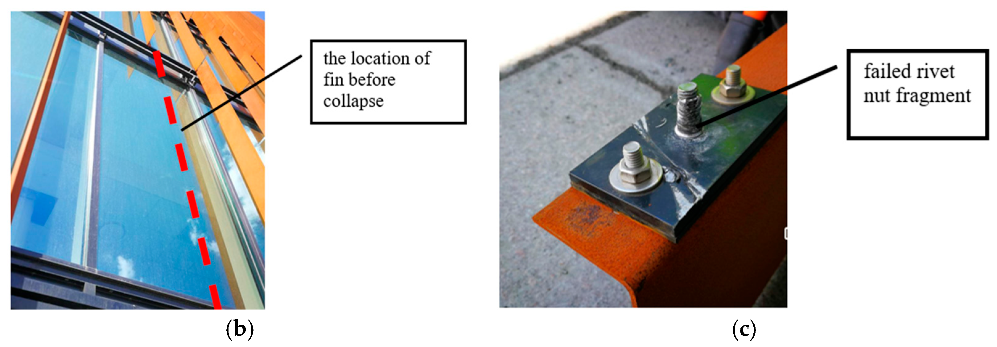
The failure of rivet nuts can lead to partial detachment of the suspended façade due to the disintegration of individual members. Figure 3 features sun protection elements (fins) on the façade (Figure 3a). This was the intention of the client and the architect and, as mentioned above, such a solution protects the envelope and interior spaces from direct sunlight and subsequent heating. To facilitate the installation of these fins around the building, a substructure was constructed on brackets fixed to the glazed façade of the aluminium frame, to which the fins themselves are then attached. While the substructure is visible from both outside and inside through the glazed part of the façade, the connection between the substructure and the fins was made using rivet nuts to enhance aesthetics and facilitate assembly. Figure 3a shows the structural solution for the façade with the fins. During construction, one of the fins collapsed shortly after installation for no apparent reason (Figure 3b,c).
After inspecting the fallen “fin”, the seriousness of the situation was recognised and the entire façade was examined. The inspection revealed several fins with loose movement at the rivet nut joints. It was concluded that the rivet nuts did not provide the required load-bearing capacity, and extensive reinforcement work was carried out, replacing the rivet nuts with conventional bolt and nut connections. During the research it was noted that there is a lack of understanding in the design and calculation methodology needed to determine their load-bearing capacity for use in construction. Additionally, there is a deficiency of rivet nuts with a European Technical Assessment certificate, and manufacturers often issue tensile load capacities for rivet nuts without conclusive proof of the product’s technical performance in specific applications. Therefore, it can be stated that there are certain issues with the current design methods used to predict the load-carrying capacity of rivet nuts.

1.2. Evaluation and Modelling of Rivet Nut Connection Behaviour and Load Capacity: Current State and Research Gaps

The design approaches and behaviour of rivet nut connections were investigated and described in sources [6,7,8,9]. However, none of these sources provide a method that allows for the definitive prediction of the load-carrying capacity and behaviour of rivet nut connections.
The study [6] concluded that assessing a more complex bolted joint, such as a connection involving rivet nuts in tensioned joints, was an intricate process. Rivet nut manufacturers often specify the load capacity of the connection without providing detailed information on the application conditions. To verify the strength of the connection, real tests or a detailed finite element method calculation is required. Experimental testing yields realistic ultimate forces and can also be used to validate finite element simulations.
Another study [10] conducted pull-out tests on rivet nuts mounted on cold-formed steel square section members with a nominal section size of 100 × 100 mm and various wall thicknesses (2.0 to 5.0 mm). The study experimentally examined the effects of different wall thicknesses and thread sizes on the test results. The main objective was to investigate the behaviour and pull-out resistance of the rivet nut, as well as to assess the influence of different wall thicknesses of square sections on their behaviour and capacity when using blind rivet nuts in mild and ultra-hollow steel structures. Additionally, the impact of rivet nut sizes (M10 and M12) on the pull-out resistance was explored.
The embedment characteristics of rivet nuts are also explored, for example, in the study “Reproducing the experimental torque-to-turn resistance of blind rivet nuts using FEA” [11]. The aim of this study was to understand and replicate rivet nut embedment through finite element analysis. The researchers employed finite element analysis to simulate the rivet nut installation process, which involves significant plastic deformation and contact pressures. They developed a strategy to accurately model this process. The results were validated against experimental data, demonstrating consistency in the shape of the deformed stud nut and the evolution of the installation force. The study also examined methods to enhance the torsional resistance of these fasteners.
Various specific studies are conducted, exploring different materials to be bonded and the diverse performance characteristics of rivet nuts. For example, the fatigue resistance of rivet nuts when installed in carbon fibre reinforced plastic was examined in studies [12,13]. The installation of rivet nuts in carbon fibre reinforced plastic can induce significant stresses that have the potential to cause damage. However, the studies demonstrate that the compressive stresses resulting from the installation of stud nuts can actually enhance the fatigue life of a carbon fibre reinforced plastic specimen, suggesting that stud nuts could be a viable method for strengthening such structures. The FEA study [14] provides a comprehensive comparative analysis of various reinforcement techniques aimed at addressing the issue of insufficient transverse connectivity in prestressed concrete box girder bridges, focusing specifically on the use of concrete-filled steel tube trusses and diaphragms as effective solutions to improve structural performance and stability. In general, the behaviour and load capacity of both conventional rivets and rivet nuts have been extensively studied under the conditions required by each industry.
The studies published to date do not propose a method for determining the load-carrying capacity of rivet nut connections that is directly applicable to façade structures. Therefore, there is a justified need for further research to develop and validate such a method. Consequently, the aim of the current investigation is to generalise the method for determining the load-carrying capacity of rivet nut connections. The proposed method should be verified through experiments and finite element method (FEM) analysis.

2. Materials and Methods

2.1. Description of Object of Investigation

After reviewing the literature on rivet nut connections, it is evident that such connections have potential in façade structures. An M6 rivet nut (Lemvigh-Müller a/s, Denmark) has been selected as the object of study. M6 screws are widely used in façade construction for attaching various finishes such as window sills, fins, aluminium panels (rainscreens), etc. They are comparable to 5.5 mm diameter self-tapping screws, but with the advantage that the bolt can be reused in the same hole. The aforementioned finishing elements are fixed to a substructure consisting of aluminium alloy profiles. The wall thickness of the aluminium alloy profile substructure is typically in the range of 2–5 mm, as shown in Figure 4.
The study will differentiate between nuts made of aluminium alloy (EN AW 5052 H32) and stainless steel (AISI 303 1.4305). Aluminium nuts are 3–6 times cheaper than stainless steel nuts, but are expected to become loose at lower loads compared to stainless steel. This aspect will be addressed in the work to compare aluminium alloy and stainless steel rivet nuts. The work will also cover the four basic material thicknesses. The thickness of the base material has a significant influence on the load-carrying capacity of the rivet nut joint. Base materials of 2, 3, 4 and 5 mm thickness will be considered, which will be EN AW 6060 T66 aluminium alloy profile. Aluminium of this alloy and thickness is often used as a substructure frame or reinforcing profile for facade finishes.
A description of the selected object of investigation is shown in Figure 4. In total, five samples are considered in the study, with one sample featuring an aluminium rivet and four samples featuring stainless steel rivets.
Aluminium M6 threaded studs are only available for a base material thickness of 2 mm, so the effect of nut materials on the behaviour of the connection will be considered at this thickness. Table 1 summarises the parameters of the five samples included in the current study.
Specimen groups 1 and 2 will be compared with each other to evaluate the behaviour of aluminium alloy and stainless steel rivets. Samples 2 to 5 will be compared to assess the effect of the profile wall thickness on the load-carrying capacity of the connection.

2.2. Development of a Methodology for Assessing the Tensile Load-Bearing Capacity of Rivet Nut Connections in Aluminium Alloy Profiles

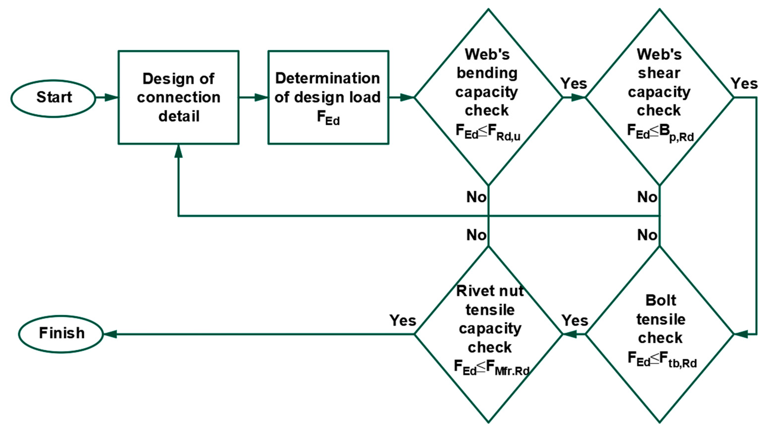
The design method, generalised in the current study, was developed based on the requirements of standards [15]. The method was supplemented by information from sources [16,17], which relate to the specific tension rivet nut connection under consideration. These sources discuss the load-bearing capacity of the thread and the buckling of the profile web. The information related to the design method for determining the tensile load-bearing capacity of a rivet nut connection with an aluminium alloy profile is summarised in Figure 5. As shown in Figure 5, the load-carrying capacity of the considered connection should be determined by considering the load capacities of the metal profile, the rivet, and the rivet’s nut. The load capacities of the thread and the buckling of the profile web should also be taken into account.
The load-carrying capacity of the considered connection should be specified as the minimum among the load capacities shown in Figure 5. The load-carrying capacity of a rivet nut connection with an aluminium alloy profile should be determined using the algorithm illustrated in Figure 6.
So, the suggested design method for tensile load-bearing capacity determination of a rivet nut connection with an aluminium alloy profile includes the following major design stages:
  • Check the web’s stability of the profile.
  • Check the aluminium alloy profile web’s strength in shear.
  • Check of the rivet’s nut.
  • Check of the rivet’s strength in tension.
The numerical values of different parameters used in the algorithm should be determined by the Formulas (1)–(8), shown below. Load-carrying capacity of the rivet in tension should be determined by Equation (1):
F t b , R k = 0.9 · f u b A s γ M 2
where Ftb,Rk—load-carrying capacity of the rivet in tension; fub—tensile strength of the rivet’s material; As—area of the rivet’s cross-section working in tension; Υm,2—partial safety factor.
Load-carrying capacity of the rivet nut should be determined by Equation (2):
F t R , R k = 47 d 2 γ M 3
where Ftr,Rk—load-carrying capacity of the rivet nu tin tension; d—diameter of the tensioned rivet; Υm,3—partial safety factor for the rivet’s connection.
Aluminium alloy profile web’s load-carrying capacity in shear should be determined by Equation (3) [18]:
B p , R k = 0.6 π d m t p f u γ M 2
where Bp,Rk—aluminium alloy profile web’s load-carrying capacity in shear; dm—diameter of the nuts head; tp—profile web’s thickness; fu—profile’s material ultimate tensile strength.
The rivet nut has the peculiarity that the riveting process creates a deformed flange which clamps and secures the nut in the base material. To account for the resistance of the rivet flange in shear, in this work, Formula (4) should be used to determine the shear load-carrying capacity of the rivet nut’s flange:
B p r , R k = 0.6 π d t r f u m γ M 2
where Bpr,Rk—load-carrying capacity in shear of the rivet nut’s flange; d—internal diameter of the rivet nut’s flange; tr—thickness of the of the rivet nut’s flange; fum—ultimate tensile strength of the rivet nut; Υm,2—partial safety factor.
Pull-through strength of the profile’s material should be determined by Equations (5) and (6) for stainless steel and aluminium alloy, correspondingly:
F o , R k = 0.47 · t s u p d f y γ M 3
F o , R k = 0.20 · t s u p d f o γ M 3
where F0,Rk—pull-through strength of the profile’s material; tsup—thickness of the profile’s material; d—hidden rivet diameter; fy—yielding strength of the stainless steel; f0—elastic limit strength of aluminium alloy; Υm,3—partial safety factor for the rivet’s connection.
One of the special features of the rivet nut connection is that the rivet-to-nut connection involves different materials and nut configurations compared to the traditional bolt and rivet connections. In classical design, the issue of the load-bearing capacity of the thread in shear does not arise, as tests have shown that the weak point of bolts and rivets produced according to standards is the shank. However, in the bolt-to-threaded stud nut connection, weaknesses related to the nut thread [19,20] can occur. This also raises the question of the shear capacity of the thread. Eurocodes do not consider the shear capacity of the thread, so a calculation methodology has been adopted to determine the theoretical capacity. The methodology outlined in the referenced publication is applied for this study, and the calculation sequence is summarised in Formula (7) to determine the shear capacity of the rivet nut thread:
F t v , R k = α v f u m A τ γ M 2
A τ = m d τ π
where Ftv,Rk—strength in shear of the nut’s thread; αv—factor influencing the load-carrying capacity in shear of bolted and riveted connections. For stainless steel and aluminium alloys αv = 0.5;—ultimate tensile strength of the rivet nut; Aτ—thread area in shear; m—screwing depth; dτ—thread shear diameter.

2.3. Experimental Trials

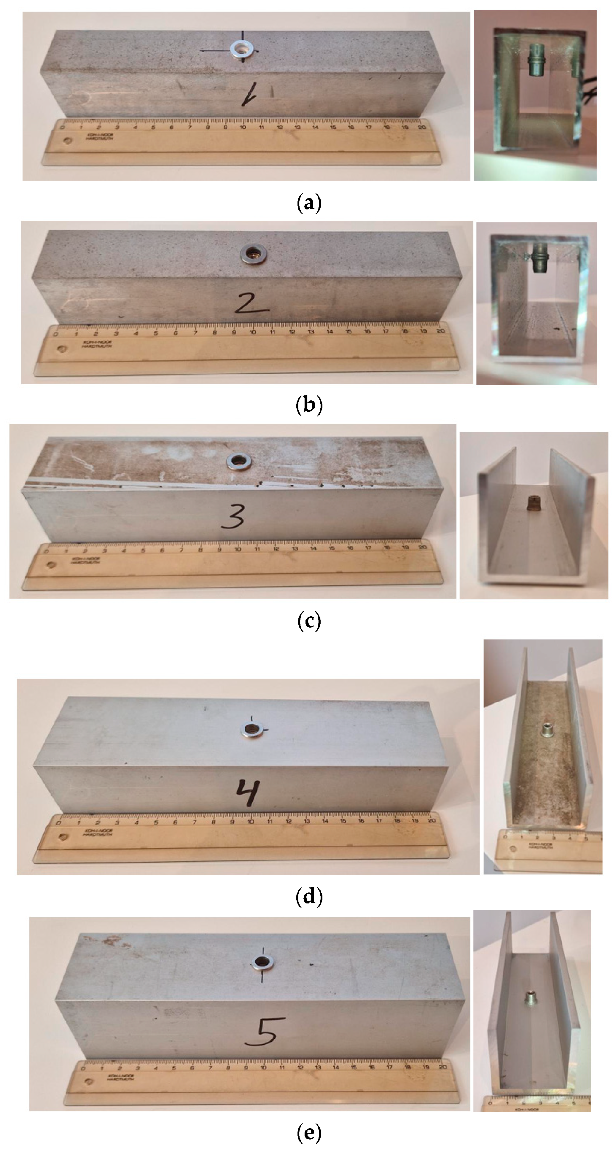
The laboratory experiment was conducted to validate the method described in Section 2.2 of the current study. Each of the five specimen groups, as mentioned in Table 1, includes five specimens. Each sample consists of a 200 mm long aluminium profile with a rivet nut and bolt positioned at the centre of the span. The specimens from all five groups are shown in Figure 7.
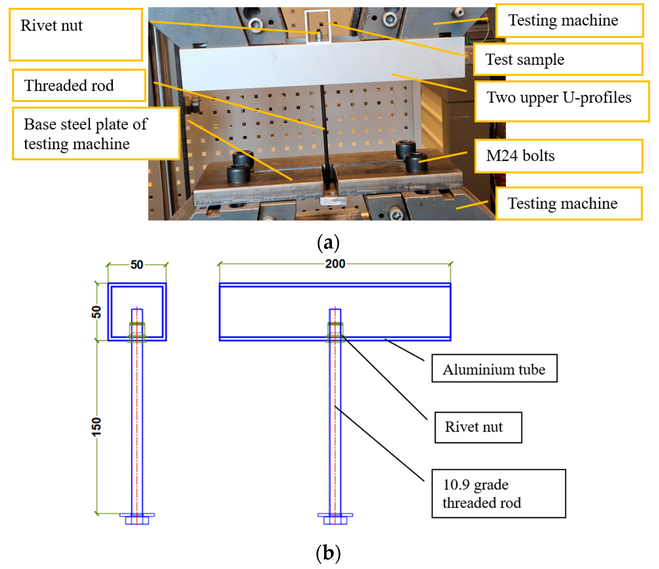
The laboratory experiment was conducted using a Zwick/Roell Z600 (ZwickRoell GmbH & Co. KG, Ulm, Germany) tension/compression electro-mechanical testing machine with a load capacity of 600 kN. All 25 specimens were loaded at a velocity of 6 mm/min. Therefore, the loading can be classified as static.
The specimens were supplemented with a 200 mm long M6 threaded rod, one end of which was screwed into the stud nut of the sample, while the other end was inserted into the bottom plate of the machine. A diagram of the specimen testing setup under laboratory conditions can be seen in Figure 8.
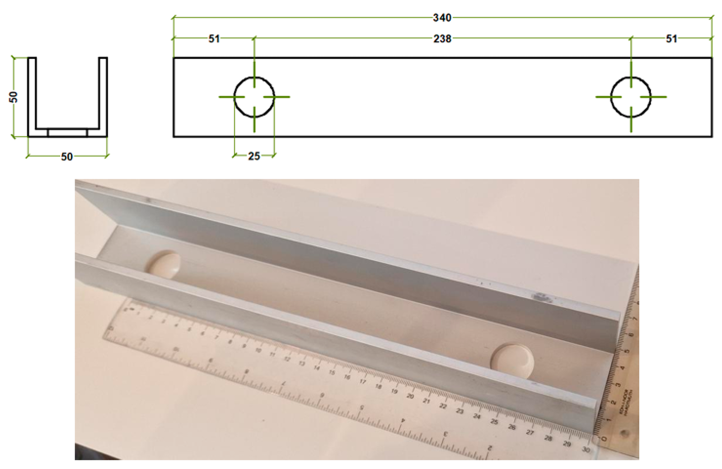
Additionally, two upper U-profiles made of aluminium alloy, which will be fixed to the machine with M24 bolts, need to be prepared. Two 50 × 50 mm aluminium alloy EN AW 6060 T66 U-profiles with a web thickness of 5 mm are used as the upper parts for the placement of the specimens in the loading machine. Figure 9 shows the required dimensions of the U-profile and the prepared details.
The samples will be positioned within the upper part of the 100 mm span (see Figure 10). The purpose of this span is to accommodate the deflection of the base material web and to compare how, and if, the bearing capacity of the joint varies with the thickness of the base material.
It was anticipated that the base material around the rivet nut would buckle, as shown in Figure 10b, and that this buckling would be more pronounced for thinner materials, thus affecting the overall load-carrying capacity of the specimens being tested.

2.4. Experimental Trials

To better understand the behaviour of the rivet nut connection and to develop a numerical model for predicting its load-carrying capacity, a finite element analysis was conducted in this study. The finite element models (FEM) were created using Dlubal RFEM 6. In the FEM, only the flange of the rivet is considered within the rivet nut body structure. For the tensile strength of the connection, the interaction between the rivet flange and the profile web will be decisive. The schematic of the rivet nut connection and its developed FEM is shown in Figure 11.
The mechanical properties of the components of the connection were selected based on the manufacturer’s guidelines. The rivets were made from EN AW-5052 H32 aluminium alloy and AISI 303 1.4305 stainless steel. The profiles were made from EN AW 6060 T66 aluminium alloy.
The material model for the rivet flange and profile was assigned a bilinear plastic property to better understand the change in the slope of the load–displacement diagram observed in the experiment. When the yield strength of the material is reached, the model enters a perfectly plastic state with a small plastic modulus.
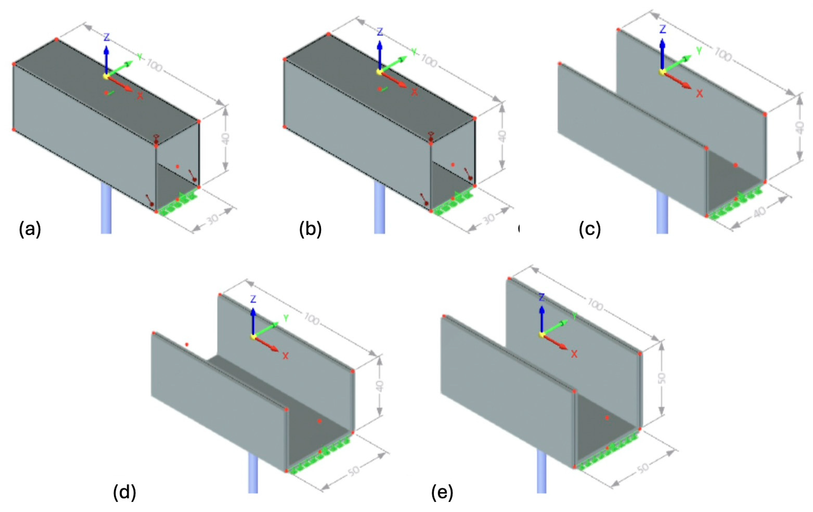
A corresponding model was developed for each group of samples. Five FEM models were created. The models mainly differed in the profile cross-section and web thickness dimensions of the samples, except for groups 1 and 2, where the difference lies in the material of the rivet flange. All specimens have a span of 100 mm. Figure 12 summarises the FEM models of the five specimen groups. All the specimen groups were described previously in Table 1.
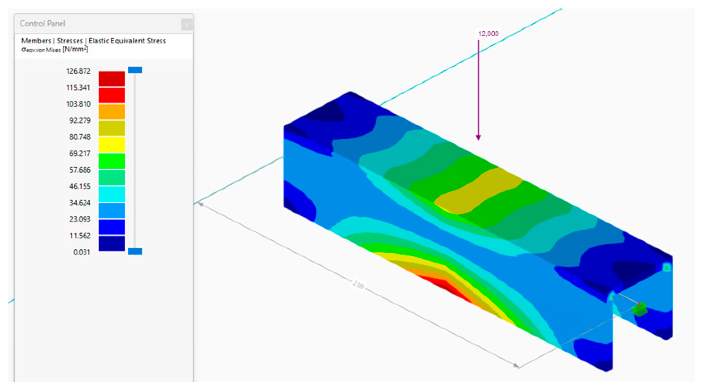
A separate FEM was developed for two 50 × 50 mm aluminium alloy EN AW 6060 T66 U-profiles with a web thickness of 5 mm. The model was used to assess the strength of the profile when loaded by a concentrated force of 12 kN, applied at the centre of the span. The maximum normal stresses acting within each U-profile were found to be 127 MPa, which is less than the design strength of the aluminium alloy EN AW 6060 T66, specified as 150 MPa. The results of the FEM analysis of the U-profiles with a web thickness of 5 mm are shown in Figure 13.

3. Results and Discussions

3.1. Results of the Laboratory and Numerical Experiments

The comparison of the results obtained from the laboratory experiment, the proposed design method for determining the tensile load-bearing capacity of a rivet nut connection with an aluminium alloy profile, and the developed FEM model was presented in the current chapter. The laboratory experiment was conducted using a Zwick/Roell Z600 tension/compression electro-mechanical testing machine with a load capacity of 600 kN. The 25 specimens, divided into five groups, were statically loaded. The specimens from all five groups were labelled as n.m, where n represented the group number and m the specimen number within that group.
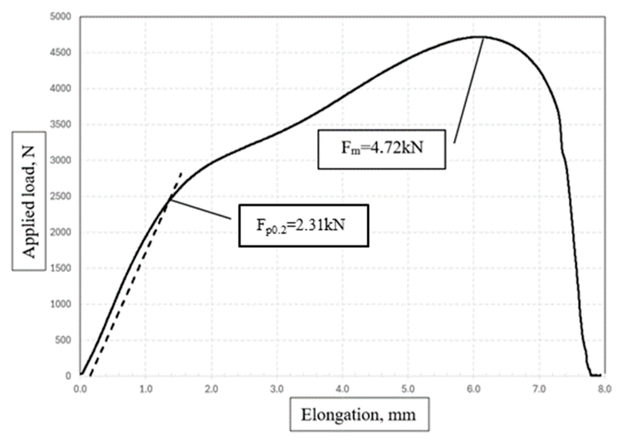
During the experimental test, the applied load and displacement diagrams showed a change in the stiffness of the connection. Additionally, the finite element analysis observed a change in slope that occurred when the rivet flange material reached its yield strength. Reaching the yield strength of the rivet flange is undesirable in order to avoid damaging the properties of the rivet. Therefore, the load-carrying capacity of the connection in the elastic stage, Fp0.2, was determined in this work and will be used for the design of the connection. The ultimate load-carrying capacity, Fm, of the specimens was also determined during the current experiment. Parameters Fp0.2 and Fm were derived from the load/elongation charts obtained for each specimen during the laboratory tests, as shown in Figure 14.
Results of the experiments, presented as load/elongation charts obtained for the first group of specimens, are shown in Figure 15 by the dotted lines. Each of the five charts in Figure 15, represented by dotted lines, corresponds to one of the five specimens in the group. The load-carrying capacity of the connection in the elastic stage, Fp0.2, for the first group of specimens varies from 2.24 to 2.40 kN. The ultimate load-carrying capacity, Fm, for the first group of specimens ranges from 4.20 to 4.72 kN. The solid red line indicates the results obtained from the developed FEM model for the first group of specimens. The horizontal blue solid line represents the load-carrying capacity Fp0.2, obtained for the first group of specimens using the proposed design method for determining the tensile load-bearing capacity of a rivet nut connection.
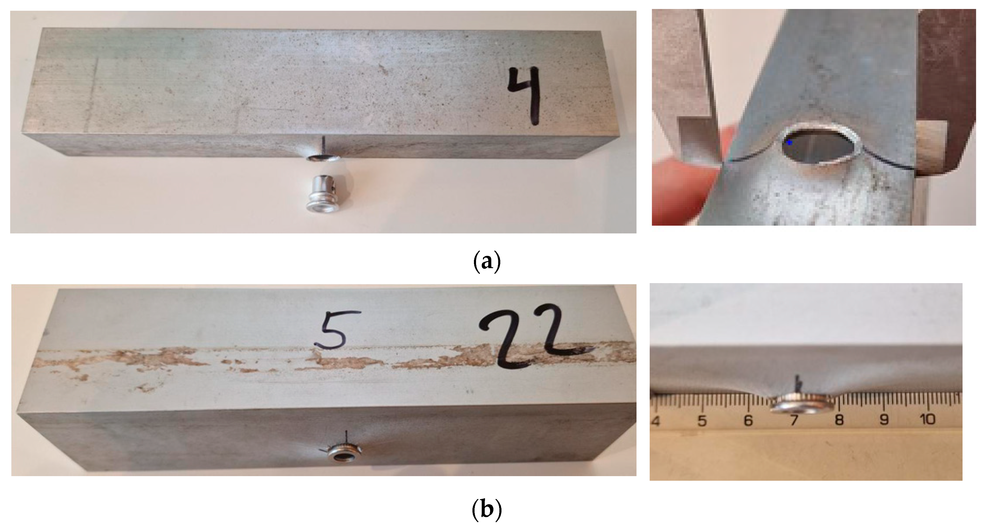
The failure of the connection occurred due to the pull-out of the rivet through the profile web. This failure mode was observed in the first four groups of specimens. The web of specimen 1.4 from the first group, after the rivet pull-out, is shown in Figure 16a. Pull-out of the rivet was not observed in the fifth group, owing to the increased web thickness of the profile up to 5 mm. The rivet’s resistance point at the profile web of specimen 5.2 is shown in Figure 16b.
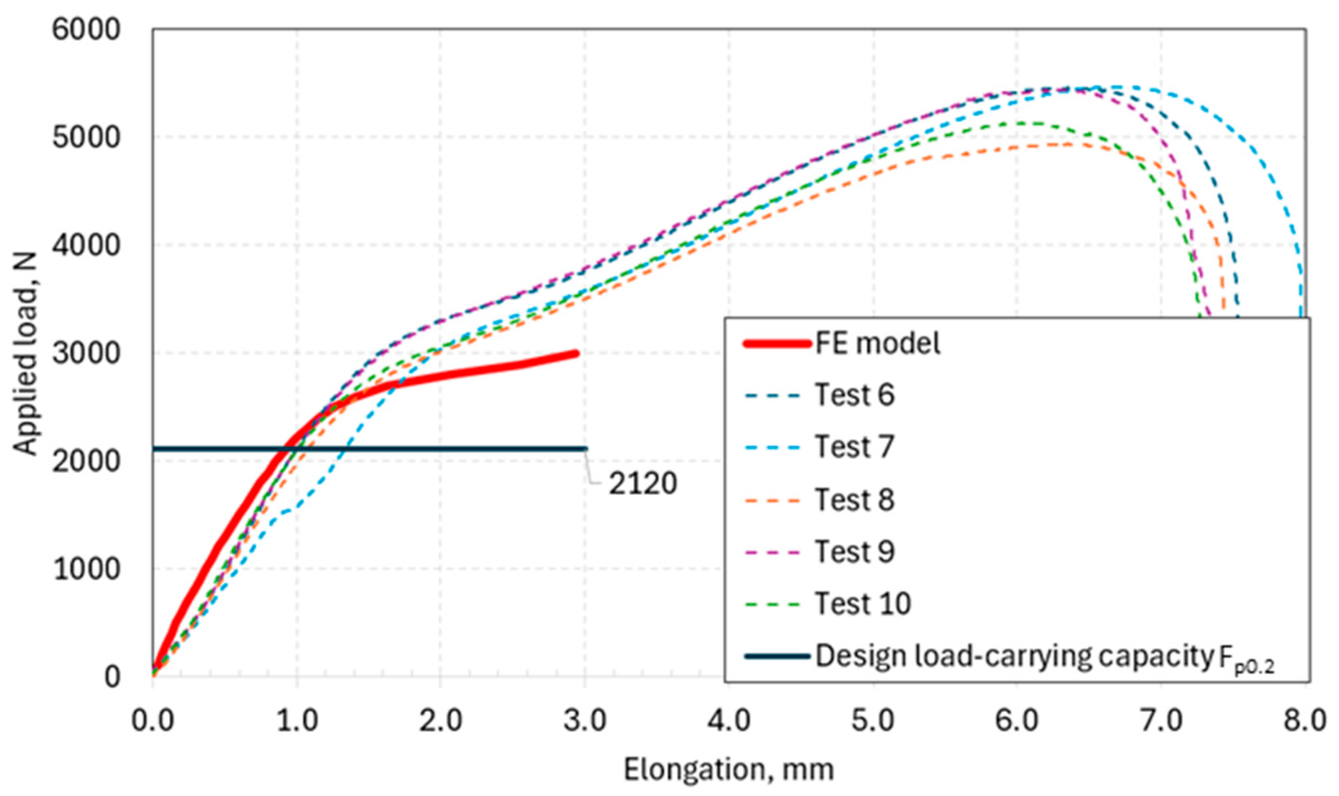
Results of the experiments, obtained for the second group of specimens, are shown in Figure 17. The load-carrying capacity of the connection in the elastic stage, Fp0.2, for the second group ranges from 2.37 to 2.84 kN. The ultimate load-carrying capacity, Fm, for the second group varies from 4.94 to 5.47 kN.
Results of the experiments, obtained for the third group of specimens, are shown in Figure 18. The load-carrying capacity of the connection in the elastic stage, Fp0.2, for the third group ranges from 4.40 to 4.55 kN. The ultimate load-carrying capacity, Fm, for the third group varies from 7.26 to 7.55 kN.
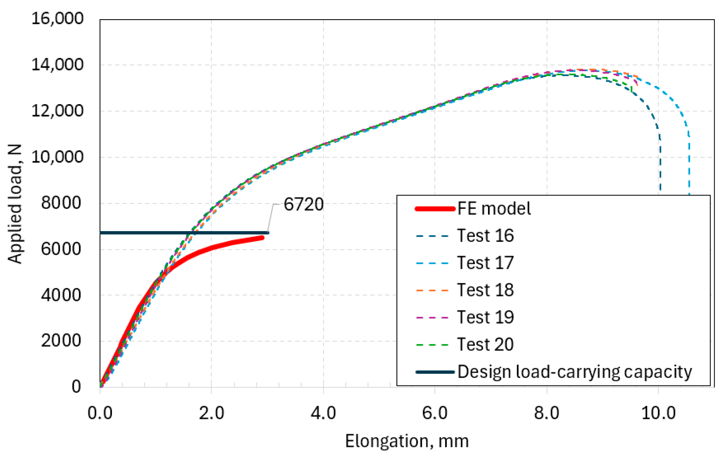
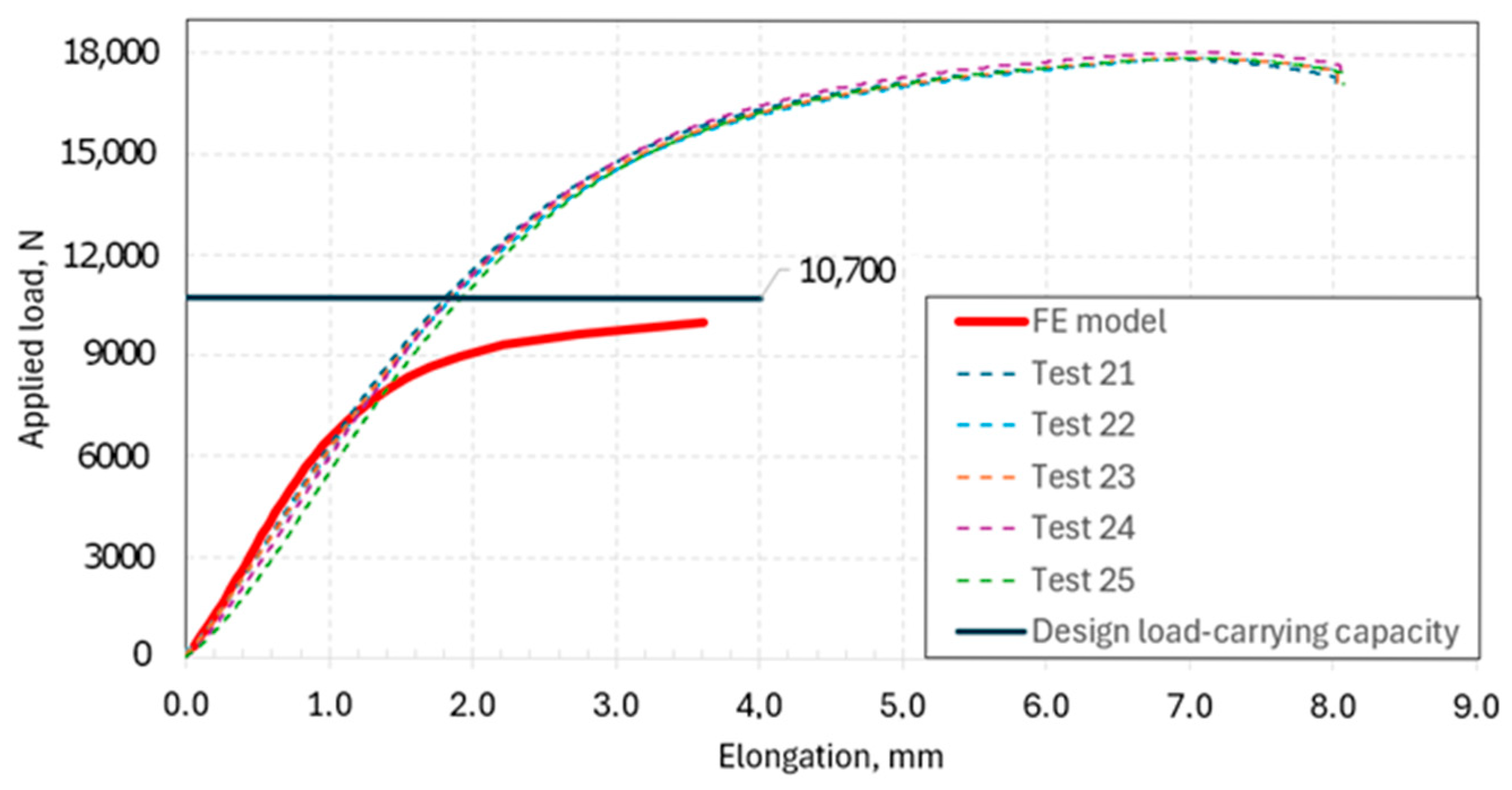
Results obtained for the fourth and fifth groups of specimens were similar to those obtained for the first three groups, as mentioned above. The load/elongation charts for the fourth and fifth groups are shown in Figure 19 and Figure 20, respectively.
The load-carrying capacity of the connection in the elastic stage, Fp0.2, for the fourth and fifth specimen groups ranges from 6.27 to 6.75 kN and from 10.56 to 11.72 kN, respectively. The ultimate load-carrying capacity, Fm, for the fourth and fifth specimen groups varies from 13.56 to 13.83 kN and from 17.89 to 18.08 kN, respectively.
It was shown that using a nut made of AISI 303 1.4305 grade stainless steel, instead of AW 5052 H32 grade aluminium alloy, enables an increase of 18.33% in the load-carrying capacity of the connection in the elastic stage, Fp0.2. The ultimate load-carrying capacity, Fm, of the specimens increases by 15.89% at the same time. Increasing the web thickness of aluminium profiles from 2 mm to 5 mm results in a 4.13-fold increase in the load-carrying capacity of the connection in the elastic stage, Fp0.2. The ultimate load-carrying capacity, Fm, of the specimens grows by a factor of 3.31.
The standard deviation for the load-carrying capacity of the connection in the elastic stage, Fp0.2, varies from 0.06 to 0.46 kN throughout the experiment for all five specimen groups. The standard deviation for the ultimate load capacity, Fm, varies from 0.08 to 0.24 kN. The observed variation factors for both Fp0.2 and Fm range from 0.01 to 0.06 and from 0 to 0.06, respectively.
A comparison between the load-carrying capacity of the connection in the elastic stage, Fp0.2, obtained through laboratory experiments and the proposed design method indicates that the discrepancy does not exceed 10% overall. For specimen groups three, four, and five, the difference is within the range of 0.4% to 10.4%. For specimens 1.1 and 2.2, the difference exceeds 13.2% and 32%, respectively.
The comparison of the load-carrying capacity of the connection in the elastic stage, Fp0.2, obtained through laboratory experiments and the developed FEM model, indicates that the differences are 15.6%, 5.2%, 18.7%, 30.54%, and 34.11% for the first, second, third, fourth, and fifth specimen groups, respectively. Therefore, it can be concluded that the proposed design method enables a reasonably accurate prediction of the tensile load-bearing capacity of a rivet nut connection with an aluminium alloy profile.
It was shown that the developed FEM model can predict the tensile load-bearing capacity of the rivet nut connection with reasonable accuracy only up to the point where the stiffness changes, at Fp0.2. The model can be considered adequate, with Fp0.2 representing the load-carrying capacity of a rivet nut connection with an aluminium alloy profile. Beyond this point, further calculation until the rivet is pulled out is not possible. This limitation can be explained by the assumptions inherent in the elastic-ideal-plastic material model. Therefore, the material behaviour model should be refined to enable the prediction of the connection’s behaviour in the zone from Fp0.2 to Fm. However, this correction of the FEM model, based on the material behaviour of the rivet nut and profile, can be considered as a future stage of the current study.

3.2. Potential Extension of the Method for Evaluating Rivet Nut Load Capacity in Composite and Hybrid Profiles

The possibility of using the current method to predict the tensile load-bearing capacity of a rivet nut connection for composite profiles, including pultruded profiles (Figure 21) [21], can be considered a direction for the extension of the current study.
The current method could potentially be used to evaluate the load-carrying capacities of rivets in suspended facades with sandwich panels, where different structural materials can be used for the outer and inner layers, as well as for load-bearing framework members [22,23].
Using load-carrying profiles made from fibre-reinforced plastics and timber-based composites, such as plywood, allows for an increase in specific load-carrying capacity and a reduction in the dead weight of façade structures. The fire resistance of façades with FRP load-bearing profiles and timber-based composites can be considered a separate topic for further investigation [24].
As the popularity and utilisation of composite materials replacing steel grow rapidly, so does the need to establish effective mechanical connections with these composites to enhance the overall performance of the structure. The assessment of the tensile load-bearing capacity of rivet nut connections is particularly important when the connection is used for fibre-reinforced polymers or various hybrid-steel composite elements, as these tend to respond differently to local fastener loads compared to steel [25].

4. Conclusions

The design method for determining the tensile load-bearing capacity of a rivet nut connection with an aluminium alloy profile, based on the requirements of standards LVS EN 1993-1-8:2025 [26], LVS EN 1999-1-1:2023 [27], and LVS EN 1999-1-4:2023 [28], was developed. The load-carrying capacity of the considered connection is determined by taking into account the load capacities of the metal profile, rivet, and rivet nut. The load capacities of the thread and the buckling of the profile web should also be considered. The developed method was validated through laboratory experiments and finite element analysis (FEA).
Twenty-five laboratory specimens, divided into five groups and differing by the thickness of the square hollow and U-shaped aluminium profiles’ webs and rivet nut materials, were tested. The aluminium profiles were made of grade AW-6060 T66 aluminium alloy. The web thicknesses ranged from 2 mm to 5 mm. The specimens included hollow aluminium profiles with dimensions 30 × 40 mm and 40 × 40 mm U-profiles. M6 threaded rods of grade 10.9 with nuts made of AISI 303 1.4305 grade stainless steel and AW-5052 H32 grade aluminium alloy were used.
It was shown that using nuts made of AISI 303 1.4305 grade stainless steel instead of AW-5052 H32 grade aluminium alloy increased the load-carrying capacity of the connection in the elastic stage, Fp0.2, by 18.33%. The ultimate load capacity, Fm, increased by 15.89% at the same time.
Increasing the web thickness of aluminium profiles from 2 mm to 5 mm resulted in a 4.13-fold increase in the load-carrying capacity in the elastic stage, Fp0.2. The ultimate load capacity, Fm, grew by a factor of 3.31.
The comparison of the load-carrying capacity of the connection in the elastic stage, Fp0.2, obtained through laboratory testing and the proposed design method, indicates that the overall difference did not exceed 10%. Therefore, the developed method can be considered valid.
Finite element models (FEM) were developed in Dlubal RFEM 6. It was demonstrated that the FEM model can predict the tensile load-bearing capacity with reasonable accuracy only up to the stiffness change point, Fp0.2. The FEM model can be considered adequate, with Fp0.2 representing the load-carrying capacity of a rivet nut connection with an aluminium alloy profile.

Author Contributions

Conceptualization, A.Z. and D.S.; methodology, A.Z. and D.S.; software, A.Z. and J.S.; validation, A.Z., E.B. and D.S.; formal analysis, J.S.; investigation, A.Z.; resources, E.B.; data curation, J.S.; writing—original draft preparation, D.S., A.Z., E.B. and A.P.; writing—review and editing, V.L.; visualisation, A.Z., A.P. and V.L.; supervision, D.S., E.B. and J.S.; project administration, D.S. and J.S.; All authors have read and agreed to the published version of the manuscript.

Funding

This research was funded by Doctoral academic career grant No. 1067. European Union Recovery and Resilience Facility funded project No. 5.2.1.1.i.0/2/24/I/CFLA/003 “Consolidation and management changes at Riga Technical University, Liepaja University, Rezekne Academy of Technologies and the Latvian Maritime Academy and Liepaja Maritime College towards excellence in higher education, science and innovation.”

Data Availability Statement

The original contributions presented in this study are included in the article. Further inquiries can be directed to the corresponding authors.

Acknowledgments

During the preparation of this manuscript, the authors used “OpenAI GPT-4o mini” for the purposes of improving the clarity, grammar, and coherence of the English text. The authors have reviewed and edited the output and take full responsibility for the content of this publication.

Conflicts of Interest

The authors declare no conflicts of interest.

References

  1. Yazdi Bahri, S.; Alier Forment, M.; Sanchez Riera, A.; Bagheri Moghaddam, F.; Casañ Guerrero, M.J.; Llorens Garcia, A.M. A Literature Review on Thermal Comfort Performance of Parametric Façades. Energy Rep. 2022, 8, 120–128. [Google Scholar] [CrossRef]
  2. Galyamichev, A.; Gerasimova, E.; Egorov, D.; Serdjuks, D.; Grossman, A.; Lysenko, D. Bearing Capacity of Riveted Connections of Mineral Wool Sandwich Panels. Mag. Civ. Eng. 2022, 112, 11202. [Google Scholar] [CrossRef]
  3. Buka-Vaivade, K.; Serdjuks, D.; Pakrastins, L. Cost Factor Analysis for Timber–Concrete Composite with a Lightweight Plywood Rib Floor. Buildings 2022, 12, 761. [Google Scholar] [CrossRef]
  4. Ziverts, A. Design Methodology for Tensile Load-Bearing Capacity Determination of a Rivet Nut Connection with an Aluminium Alloy Profile. Master’s Thesis, Riga Technical University, Riga, Latvia, 2025. [Google Scholar]
  5. Setiawan, R.I.; Ramadhani, S. Pengaplikasian Material Aluminium Composite Panel Pada Perancangan Apartemen Dan Soho Di Kota Surabaya. J. Lingkung. Karya Arsit. 2023, 2, 80–86. [Google Scholar] [CrossRef]
  6. Borowiecki, C.; Iluk, A.; Krysiński, P.; Rusiński, E.; Sawicki, M. Numerical and Experimental Investigation of Bolted Connections with Blind Rivet Nuts. In Proceedings of the 14th International Scientific Conference: Computer Aided Engineering, Wrocław, Poland, 20–23 June 2018; Rusiński, E., Pietrusiak, D., Eds.; Springer International Publishing: Cham, Switzerland, 2019; pp. 88–95. [Google Scholar]
  7. Satheesh Kumar, K.V.; Selvakumar, P.; Jagadeeswari, R.; Dharmaraj, M.; Uvanshankar, K.R.; Yogeswaran, B. Stress Analysis of Riveted and Bolted Joints Using Analytical and Experimental Approach. Mater. Today Proc. 2021, 42, 1091–1099. [Google Scholar] [CrossRef]
  8. de Velde, A.V.; Ivens, J.; Maeyens, J.; Coppieters, S. The Effect of the Setting Force on the Fatigue Resistance of a Blind Rivet Nut Set in CFRP. Key Eng. Mater. 2022, 926, 1498–1504. [Google Scholar] [CrossRef]
  9. Van de Velde, A.; Debruyne, D.; Maeyens, J.; Wevers, M.; Coppieters, S. Towards Best Practice in Numerical Simulation of Blind Rivet Nut Installation. Int. J. Mater. Form. 2021, 14, 1139–1155. [Google Scholar] [CrossRef]
  10. Cosgun, S.I. Experimental Study on the Pull-Out Capacity of Blind Rivet Nuts (BRNs) Mounted on Cold-Formed Square Hollow Section Members with Different Wall Thickness. Sinop. Uni. J. Nat. Sci. 2023, 8, 202–215. [Google Scholar] [CrossRef]
  11. Reproducing the Experimental Torque-to-Turn Resistance of Blind Rivet Nuts Using FEA, AIP Conference Proceedings, AIP Publishing. Available online: https://pubs.aip.org/aip/acp/article-abstract/1896/1/110005/998803/Reproducing-the-experimental-torque-to-turn?redirectedFrom=fulltext (accessed on 25 August 2025).
  12. GÓRKAL 70 Product Description. Www.gorka.com.pl. 2020. Available online: https://www.gorka.com.pl/pdf/en/g70_katalog_en.pdf (accessed on 25 August 2025).
  13. Van de Velde, A.; Maeyens, J.; Ivens, J.; Coppieters, S. The Effect of the Setting Force on the Static Strength of a Blind Rivet Nut Set in CFRP. Compos. Struct. 2023, 307, 116640. [Google Scholar] [CrossRef]
  14. Li, P.; Yang, C.; Xu, F.; Li, J.; Jin, D. Reinforcement of Insufficient Transverse Connectivity in Prestressed Concrete Box Girder Bridges Using Concrete-Filled Steel Tube Trusses and Diaphragms: A Comparative Study. Buildings 2024, 14, 2466. [Google Scholar] [CrossRef]
  15. EN 1993-1-8; Eurocode 3: Design of Steel Structures—Part 1–8: Design of Joints. CEN: Brussels, Belgium, 2005.
  16. Dose, G.F.; Schwarz, W. Nachweis Der Abstreifsicherheit Axial Beanspruchter Einschraubverbindungen. 2000. Available online: https://www.hexagon.de/dose/dose2.pdf (accessed on 10 September 2025).
  17. Joints in Steel Construction: Simple Joints to Eurocode 3; Steel Construction Institute: Bracknell, UK; British Constructional Steelwork Association Ltd.: Ascot, London, 2011; ISBN 978-1-85942-201-4.
  18. Witek, L. Numerical Simulation of Riveting Process Using Blind Rivet. Aviation 2006, 10, 7–12. [Google Scholar] [CrossRef]
  19. Croccolo, D.; De Agostinis, M.; Fini, S.; Mele, M.; Olmi, G.; Scapecchi, C.; Tariq, M.H.B. Failure of Threaded Connections: A Literature Review. Machines 2023, 11, 212. [Google Scholar] [CrossRef]
  20. Egorov, D.; Galyamichev, A.; Gerasimova, E.; Serdjuks, D. Stress-Strain State of Fiber Cement Cladding within Curtain Wall System. Mag. Civ. Eng. 2020, 97, 9709. [Google Scholar] [CrossRef]
  21. Barkanov, E.; Akishin, P.; Namsone, E.; Auzins, J.; Morozovs, A. Optimization of Pultrusion Processes for an Industrial Application. Mech. Compos. Mater. 2021, 56, 697–712. [Google Scholar] [CrossRef]
  22. Galyamichev, A.; Kirikova, V.; Gerasimova, E.; Sprince, A. Bearing Capacity of Facade Systems Fixing to Sandwich Panels. Mag. Civ. Eng. 2018, 78, 30–46. [Google Scholar] [CrossRef]
  23. Studziński, R.; Ciesielczyk, K. Use of Blind Rivets in Sandwich Panels—Experimental Investigation of Static and Quasi-Cyclic Loading. Buildings 2020, 10, 155. [Google Scholar] [CrossRef]
  24. Nguyen, Q.; Ngo, T.; Mendis, P.; Tran, P. Composite Materials for Next Generation Building Façade Systems. Civ. Eng. Archit. 2013, 1, 88–95. [Google Scholar] [CrossRef]
  25. Yang, Y.; Bao, Y.; Liu, X.; Wang, J.; Du, F. Progressive Failure Analysis of Composite/Aluminum Riveted Joints Subjected to Pull-Through Loading. Chin. J. Mech. Eng. 2023, 36, 10. [Google Scholar] [CrossRef]
  26. LVS EN 1993-1-8:2025; 3.Eirokodekss. Tērauda Konstrukciju Projektēšana. 1-8.Daļa: Savienojumu Projektēšana. Latvijas Standards: Rīga, Latvia, 2025.
  27. LVS EN 1999-1-1:2023; 9.Eirokodekss. Alumīnija konstrukciju Projektēšana. 1-1.Daļa: Vispārīgie Noteikumi. Latvijas Standards: Rīga, Latvia, 2025.
  28. LVS EN 1999-1-4:2023; 9.Eirokodekss. Alumīnija konstrukciju Projektēšana. 1-4.Daļa: Konstrukcijas no Auksti Velmētām Loksnēm. Latvijas Standards: Rīga, Latvia, 2025.
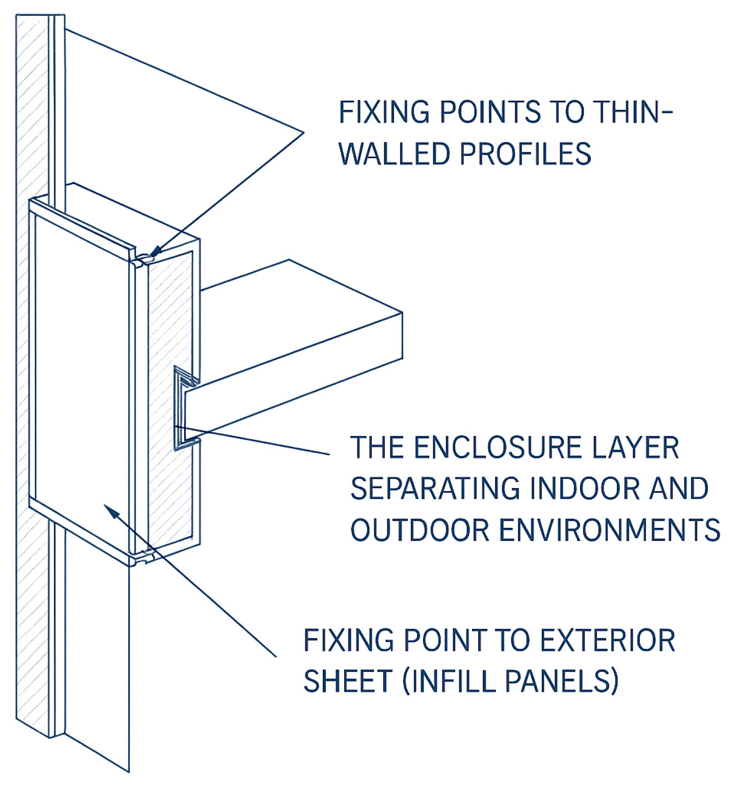
Figure 1. Sketch showing the application of rivet nuts in facades [4].
Jcs 09 00533 g001
Figure 2. Structural solutions of the facades: (a) sun protection structure “fins”; (b) suspended sheds.
Jcs 09 00533 g002
Figure 3. Suspended façade fragment of the building: (a) structural solution of the facade; (b) zone of the partial collapse of the suspended facade; (c) failure mode of the rivet nut.
Jcs 09 00533 g003aJcs 09 00533 g003b
Figure 4. Description of the selected object of investigation.
Jcs 09 00533 g004
Figure 5. Load-carrying capacities of the considered connection.
Jcs 09 00533 g005
Figure 6. Algorithm for determination the load-carrying capacity of a rivet nut connection with an aluminium alloy profile.
Jcs 09 00533 g006
Figure 7. Laboratory specimens: (a) group 1; (b) group 2; (c) group 3; (d) group 4; (e) group 5.
Jcs 09 00533 g007
Figure 8. Scheme of the specimen testing: (a) specimens’ placement in the loading machine: (b) a scheme of the specimen prepared for testing.
Jcs 09 00533 g008
Figure 9. Dimensions of upper U-profiles.
Jcs 09 00533 g009
Figure 10. The specimens’ placement at the two upper U-profiles, made of aluminium alloy EN AW 6060T66. (a) Sample 100 mm span over U-profiles; (b) expected protrusion of aluminium pipe walls.
Jcs 09 00533 g010
Figure 11. Scheme of the rivet nut connection and its developed FEM: (a) Schematic description of the FEM of rivet flange and profile connection; (b) Side view of the FEM of rivet flange and profile connection; (c) 3D view of the FEM of rivet flange and profile connection.
Jcs 09 00533 g011
Figure 12. FEM models of the five specimen groups: (a) Group 1; (b) Group 2; (c) Group 3; (d) Group 4; (e) Group 5.
Jcs 09 00533 g012
Figure 13. Results of the FEM calculation for 50 × 50 aluminium alloy EN AW 6060T66 U-profile.
Jcs 09 00533 g013
Figure 14. Example of the determination of parameters Fp0.2 and Fm based on the load/elongation curves for the specimen 1.3.
Jcs 09 00533 g014
Figure 15. Load/elongation charts, obtained for the first group of the specimens.
Jcs 09 00533 g015
Figure 16. The web of the first and fifth groups of specimens in course of the loading: (a) specimen 1.4; (b) specimen 5.2.
Jcs 09 00533 g016
Figure 17. Load/elongation charts were obtained for the second group of specimens.
Jcs 09 00533 g017
Figure 18. Load/elongation charts, obtained for the third group of the specimens.
Jcs 09 00533 g018
Figure 19. Load/elongation charts, obtained for the fourth group of the specimens.
Jcs 09 00533 g019
Figure 20. Load/elongation charts, obtained for the fifth group of the specimens.
Jcs 09 00533 g020
Figure 21. Several types of the composite pultrusion profiles can be used in the suspended facades.
Jcs 09 00533 g021
Table 1. Parameters of the considered specimens.
Number of Specimen GroupsAluminium Alloy ProfileRivet Nut
1aluminium alloy AW 6060 T66, tube,
30 × 40 mm, b = 2 mm
M6, aluminium alloy AW 5052 H32
2aluminium alloy AW 6060 T66, tube,
30 × 40 mm, b = 2 mm
M6, stainless steel AISI 303 1.4305
3aluminium alloy AW 6060 T66, channel(U-profile), 40 × 40 mm, b = 3 mmM6, stainless steel AISI 303 1.4305
4aluminium alloy AW 6060 T66, channel(U-profile), 40 × 40 mm, b = 4 mmM6, stainless steel AISI 303 1.4305
5aluminium alloy AW 6060 T66, channel(U-profile), 40 × 40 mm, b = 5 mmM6, stainless steel AISI 303 1.4305
Disclaimer/Publisher’s Note: The statements, opinions and data contained in all publications are solely those of the individual author(s) and contributor(s) and not of MDPI and/or the editor(s). MDPI and/or the editor(s) disclaim responsibility for any injury to people or property resulting from any ideas, methods, instructions or products referred to in the content.