Article

Advanced Dynamic Thermal Vibration of Thick Composited FGM Cylindrical Shells with Fully Homogeneous Equation by Using TSDT and Nonlinear Varied Shear Coefficient

Department of Mechanical Engineering, Hsiuping University of Science and Technology, Taichung 412406, Taiwan
J. Compos. Sci. 2025, 9(1), 4; https://doi.org/10.3390/jcs9010004
Submission received: 22 October 2024 / Revised: 17 December 2024 / Accepted: 26 December 2024 / Published: 30 December 2024
(This article belongs to the Section Composites Modelling and Characterization)

Abstract

:
A numerical method using advanced nonlinear shear is used to study the thermal vibration of functionally graded material (FGM) thick circular cylindrical shells. The third-order shear deformation theory (TSDT) of displacements is applied and the equations are derived of the motion of cylindrical shells and the expression of the advanced nonlinear varied shear factor. The expressions of stiffness of thick composited two-layer FGM circular cylindrical shells with sinusoidal rising temperature are applied. The partial differential equation (PDE) in dynamic equilibrium of thick FGM circular cylindrical shells is derived with respect to shear rotations and displacements under terms of thermal–mechanical loads and density inertia terms. Important parametric effects of the advanced nonlinear varied shear factor, power law index, and temperature on the stress and displacement of thick FGM circular cylindrical shells are studied. Additionally, the advanced nonlinear varied shear factor effect is included and studied for a vibrating frequency using a fully homogeneous equation.

1. Introduction

Numerical investigations of shear deformation effects on functionally graded material (FGM) laminated shells have been presented. In 2020, Shahmohammadi et al. [1] applied an isogeometric B3-spline finite strip method (IG-SFSM) to investigate vibration of FGM laminated sandwich shells, and the numerical natural frequency solutions were obtained. In 2020, Hajlaoui et al. [2] used the enhanced first-order solid-shell element formulation for the shear strain to modify the nonlinear static behavior in FGM shells. In 2019, Ghamkhar et al. [3] used Sander’s shell theory for the relations in strain and curvature displacement to study the three-layered natural frequencies of FGM cylinder-shaped shells. In 2017, Moshkelgosha et al. [4] presented a semi-analytical model to study the coupling fluid structure of FGM concentric double shells by using commercial code of the finite element method (FEM). In 2017, Hajlaoui et al. [5] used the enhanced higher-order solid-shell element formulation to study the nonlinear solutions for FGM shells. Some numerical investigations were studied for thin shells. In 2019, Fakhari et al. [6] used the code of FEM to find the natural frequency solutions of variable-thickness thin cylindrical FGM shells. In 2019, Singh and Sharma [7] presented reviews of FGM shells used in the manufacturing of load-bearing components for aircraft, etc. In 2013, Tornabene and Reddy [8] presented static studies of FGM doubly curved shells with the generalized differential quadrature (GDQ) method. In 2010, Sepiani et al. [9] used the first-order shear deformation theory (FSDT) formulation to obtain free vibration solutions for FGM cylindrical shells.
It has become more important for stress and deflection to be defined in thick material than in thin material. The FSDT or classical displacement theories were usually used in thin material, whereas the TSDT or higher-order shear deformation theory (HSDT) were usually used in thick material, where the ratio of length to thickness was less than 10, as studied by Reddy in 2007 [10]. The FSDT was a linear function of the thickness axis direction, and the TSDT was a nonlinear function of the thickness axis direction, as shown by Rafiee et al. in 2017 [11]. This is why the TSDT was studied, and it ensured the need for an advanced shear correction factor in the calculations of stress and deflection of thick materials by Kazancı in 2016 [12], Teotia and Soni in 2018 [13], D’Ottavio and Polit in 2017 [14], and Sobhani Aragh et al. in 2021 [15]. There may have been less consideration of the use of a constant shear correction factor value, e.g., 2/3 or 5/6, in the TSDT or HSDT investigations by Birman and Genin in 2018 [16], Thai and Kim in 2015 [17], Paroissien et al. in 2022 [18], and Kurpa and Shmatko in 2022 [19]. A shear-deformable beam model was included in the analysis of the thin material of structures with the virtual work principle by Banić et al. in 2024 [20]. The shear correction factor used for the FSDT and FEM studies by Benounas et al. in 2024 [21] was assumed and neglected, and the shear correction factor was used for the FSDT and shell studies by Thu et al. in 2024 [22]. Thus, the expression of the advanced shear correction factor estimated with a nonlinear varied value and developed by using the total strain energy principle was presented.
The GDQ computational experiences in laminated FGM plates and shells, including some important effects, e.g., thermal temperature and heating loads, have been presented. In 2021, Hong [23] provided the deflection and stress numerical solutions for the thermal vibration in thick FGM spherical shells with the TSDT and basic constant shear correction factor effects. For the thermal vibration of FGM circular cylindrical shells with the FSDT, using basic varied and constant values of the shear correction factor, the computational GDQ solutions were already obtained. It is novel to study the thermal displacements and stresses of GDQ solutions in nonlinear TSDT vibration and the advanced varied shear correction coefficient for FGM circular cylindrical shells. Important parametric effects of temperature and the power law index on the stress and displacement of FGM thick shells are investigated. Another important parameter for the advanced nonlinear varied shear factor is also studied using the approach of a fully homogeneous frequency equation. The author would like to clearly point out that the contribution of this paper is that the advanced varied shear correction factor effect is included in this study, which has not been included in the previous papers.

2. Formulation

The aim of this study is to understand and quantify the influence of some issues for the formulation listed in Section 1, i.e., an FGM composited material usually used in high-temperature areas. The thermal loading in a typical case study provides a sinusoidal nonlinear vibration form of temperature. The nonlinear vibration of the TSDT displacements model used varies with respect to the third order of z in the thickness direction. The variable shear coefficient is included to examine the effects in shear stress for thick shells.
For a composited FGM circular cylindrical shell with cylindrical coordinates x, θ and z subject to the temperature difference parameter T of thermal load are shown in Figure 1. The geometrical parameters are used with the parameters thickness h 1 in the inner material 1 layer and thickness h 2 in the outer material 2 layer. L denotes the axial length. h * denotes the total thickness. A power law function type of material properties in FGM shells is introduced, e.g., parameters for Young’s modulus E f g m are functions of constituent material properties P i and the power law index R n , and Poisson’s ratio ν f g m of FGM shells is used in its average form. The individual P i is used with respect to temperature T in the environment for E 1 , E 2 , ν 1 , and ν 2 of material 1 and material 2, as follows [23]:
P i = P 0 ( P 1 T 1 + 1 + P 1 T + P 2 T 2 + P 3 T 3 ) ,
in which P 0 ,   P 1 ,   P 1 ,   P 2 , and P 3 are coefficients of temperatures.

2.1. Nonlinear Displacements in TSDT

The displacement component parameters for u , v , and w of FGM thick cylindrical shells are functions of time t, in-surface coordinates x and θ , the nonlinear value of z 3 , and the coefficient c 1 of TSDT models [23,24] used in the following:
u = u 0 ( x , θ , t ) + z ϕ x ( x , θ , t ) c 1 z 3 ( ϕ x + w x ) ,
v = v 0 ( x , θ , t ) + z ϕ θ ( x , θ , t ) c 1 z 3 ( ϕ θ + w R θ ) ,
w = w ( x , θ , t )
in which u 0 and v 0 are tangential displacements in x and θ directions, respectively. w denotes transverse displacement. ϕ x , ϕ θ denote shear rotations. R denotes the middle-surface radius of circular cylindrical shells. The expression c 1 = 4/(3 h * 2 ) is used for the TSDT, and c 1 = 0 is used for the FSDT.

2.2. Stresses in Thick FGM Shells

Stress component parameters used in normal stress σ x , σ θ , and in shear stress σ x θ , σ θ z , σ x z for the (k)th layer of composited FGM thick cylindrical shells under thermal load T are used as follows [23]:
σ x σ θ σ x θ ( k ) = Q ¯ 11 Q ¯ 12 Q ¯ 16 Q ¯ 12 Q ¯ 22 Q ¯ 26 Q ¯ 16 Q ¯ 26 Q ¯ 66 ( k ) ε x α x Δ T ε θ α θ Δ T ε x θ α x θ Δ T ( k ) ,
σ θ z σ x z ( k ) = Q ¯ 44 Q ¯ 45 Q ¯ 45 Q ¯ 55 ( k ) ε θ z ε x z ( k ) ,
where α x and α θ are thermal expansion coefficients, and α x θ is the thermal shear coefficient. Q ¯ i j is the stiffness of FGM shells. For subscripts i, j = i * , j * = 4, 5 for Q ¯ i * j * , including the parameter for the advanced shear correction factor k α . ε x , ε θ , and ε x θ are denoted as in-plane strains. ε θ z and ε x z are denoted as shear strains, and they are not negligible in the thick FGM circular cylindrical shells.

2.3. External Thermal Loads

The heat conduction equation for FGM circular cylindrical shells is expressed in the following simple expression:
K ( 2 Δ T x 2 + 2 Δ T R 2 θ 2 + 2 Δ T z 2 ) = Δ T t ,
in which K = κ f g m / ( ρ f g m C v f g m ) , κ f g m is thermal conductivity, ρ f g m is density, C v f g m is specific heat, and T = T ¯ 1 z h * s i n ( π x / L ) s i n ( π θ ) s i n ( γ t ) is used for the temperature difference in sinusoidal expressions, where γ denotes the applied heat frequency and T ¯ 1 denotes the temperature amplitude. Thus, γ of the applied heat for the thermal loads could be met as follows:
L 2 K π 2 [ 1 + ( L / R ) 2 ] γ cos ( γ t ) + sin ( γ t ) = 0 ,

2.4. Dynamic Equations of Motion

The dynamic equation of motion including the TSDT effect for an FGM cylindrical shell is used in the following [23]:
N x x x + 1 R N x θ θ = I 0 2 u 0 t 2 + J 1 2 ϕ x t 2 c 1 I 3 2 t 2 ( w x ) ,
N x θ x + 1 R N θ θ θ = I 0 2 v 0 t 2 + J 1 2 ϕ θ t 2 c 1 I 3 2 t 2 ( 1 R w θ ) ,
Q ¯ x x + 1 R Q ¯ θ θ + c 1 ( 2 P x x x 2 + 2 R 2 P x θ x θ + 1 R 2 2 P θ θ θ 2 ) + q = I 0 2 w t 2 c 1 2 I 6 2 t 2 ( 2 w x 2 + 1 R 2 2 w θ 2 )
+ c 1 [ I 3 2 t 2 ( u 0 x + 1 R v 0 θ ) + J 4 2 t 2 ( ϕ x x + 1 R ϕ θ θ ) ] ,
M ¯ x x x + 1 R M ¯ x θ θ Q ¯ x = 2 t 2 ( J 1 u 0 + K 2 ϕ x c 1 J 4 w x ) ,
M ¯ x θ x + 1 R M ¯ θ θ θ Q ¯ θ = 2 t 2 ( J 1 v 0 + K 2 ϕ θ c 1 J 4 1 R w θ ) ,
where M ¯ α β = M α β c 1 P α β , Q ¯ α = Q α 3 c 1 R α , ( α , β = x , θ ) ,
N x x N θ θ N x θ = h * 2 h * 2 σ x x σ θ θ σ x θ d z ,   M x x M θ θ M x θ = h * 2 h * 2 σ x x σ θ θ σ x θ z d z ,
P x x P θ θ P x θ = h * 2 h * 2 σ x x σ θ θ σ x θ z 3 d z ,   R θ R x = h * 2 h * 2 σ θ z σ x z z 2 d z ,   Q θ Q x = h * 2 h * 2 σ θ z σ x z d z ,
I i = k = 1 N * k k + 1 ρ ( k ) z i d z , ( i = 0 , 1 , 2 , , 6 ) , where N * denotes the total number of layers, ρ ( k ) denotes the density of (k)th ply, and J i = I i c 1 I i + 2 , ( i = 1 , 4 ) , K 2 = I 2 2 c 1 I 4 + c 1 2 I 6 .
Strain–displacement relations with v 0 z = v 0 R , u 0 z = u 0 R , and w z = ϕ x z = ϕ θ z = 0 can be expressed as follows:
ε x = u x + 1 2 ( w x ) 2 = u 0 x + z ϕ x x c 1 z 3 ( ϕ x x + 2 w x 2 ) + 1 2 ( w x ) 2 ,
ε θ = 1 R v θ + 1 2 ( 1 R w θ ) 2
= 1 R v 0 θ + z 1 R ϕ θ θ c 1 z 3 ( 1 R ϕ θ θ + 1 R 2 2 w θ 2 ) + 1 2 1 R 2 ( w θ ) 2 ,
ε z z = 0 ,
ε x θ = 1 R u θ + v x + ( w x ) ( 1 R w θ )
= 1 R [ u 0 θ + z ϕ x θ c 1 z 3 ( ϕ x θ + 2 w x θ ) ]
+ v 0 x + z ϕ θ x c 1 z 3 ( ϕ θ x + 1 R 2 w x θ ) + ( w x ) ( 1 R w θ ) ,
ε θ z = v z + 1 R w θ = v 0 R + ϕ θ 3 c 1 z 2 ( ϕ θ + 1 R w θ ) + 1 R w θ ,
ε x z = u z + w x = u 0 R + ϕ x 3 c 1 z 2 ( ϕ x + w x ) + w x
Thus, a dynamic equilibrium partial differential equation (PDE) with the TSDT can be derived, and is listed in the Appendix A.

2.5. Numerical GDQ Method

The GDQ numerical method can be used to approximate the dynamic PDE (A1) into the dynamic GDQ discrete equations for grid point coordinates ( x i , θ j ) as follows:
x i = 0.5 [ 1 cos i 1 N 1 π ] L ,   I = 1 ,   2 ,     ,   N ,
θ j = 0.5 [ 1 cos j 1 M 1 π ] R ,   j = 1 ,   2 ,     ,   M ,
where N and M are grid point numbers in the x and θ directions.
The following non-dimensional X, U, V, W parameters are used in the GDQ:
X = x / L ,   U = u 0 / L ,   V = v 0 / R ,   W = w / h * .
Dynamic GDQ matrix form equations can be discretized and expressed in the following:
[ A ] { W * } = { B } ,
in which [ A ] denotes a coefficient matrix in dimensions N * * by N * * with N * * = ( N 2 ) × ( M 2 ) × 5 , which can be in terms of stiffness coefficients, density inertia terms, and GDQ weighting parameters. W * = { U 2,2 , , U N 1 , M 1 , V 2,2 , , V N 1 , M 1 , W 2,2 ,   , W N 1 , M 1 , ϕ x 2,2 , , ϕ x N 1 , M 1 , ϕ θ 2,2 , , ϕ θ N 1 , M 1 } t denotes an N * * th-order unknown column vector, and { B } = { F 1 F 1 , F 2 F 2 , F 3 F 3 , F 4 F 4 , F 5 F 5 } t is an N * * th-order external load column vector for the discretized expression F 1 , F 2 , …, F 5 . The Lahey–Fujitsu Fortran program can be used to prepare the [ A ] elements of (10).

3. Numerical Results

The FGM constituent material 1 used SUS304 and constituent material 2 used Si3N4 for the thermal calculations including the two effects of advanced k α and the TSDT. There are no other external loads except the thermal load, e.g., p 1 = p 2 = q = 0 in (A2). Values of L / R = 1, h * = 1.2 mm, h 1 = h 2 = 0.6 mm, and c 1 = 0.925925/mm2 in the TSDT, and c 1 = 0 in the FSDT, are used in the calculations.

3.1. Vibration Frequency ω m n

To obtain the calculation values of vibration frequency ω m n , the time sinusoidal forms for u 0 , v 0 , w , ϕ x , and ϕ θ are expressed as follows under f 1 = f 2 = = f 5 = 0 in (A1) for four simply supported sides and nonlinear c 1 effects:
u 0 = a m n cos ( m π x / L ) sin ( n π θ / R ) sin ( ω m n t ) ,
v 0 = b m n sin ( m π x / L ) cos ( n π θ / R ) sin ( ω m n t ) ,
w = c m n sin ( m π x / L ) sin ( n π θ / R ) sin ( ω m n t ) ,
ϕ x = d m n cos ( m π x / L ) sin ( n π θ / R ) sin ( ω m n t ) ,
ϕ θ = e m n sin ( m π x / L ) cos ( n π θ / R ) sin ( ω m n t ) ,
where ω m n denotes the natural frequency, in which the subscript m denotes the axial half-wave number and n denotes the circumferential wave number. a m n , b m n , c m n , d m n , and e m n are amplitudes. By substituting (11) into (A1), the fully homogeneous equation and ω m n can be obtained [25].

3.2. Advanced k α

Using the principle of total strain energy, the following advanced k α expression can be obtained by including nonlinear c 1 effects [25]:
k α = 1 h * F G M Z S V F G M Z I V ,
where F G M Z S V = ( F G M Z S c 1 F G M Z S N ) 2 is a function of ( h * )6, and F G M Z I V = F G M Z I 2 c 1 F G M Z I V 1 + c 1 2 F G M Z I V 2 is a function of ( h * )5, in which FGMZS, FGMZSN, FGMZI, FGMZIV1, and FGMZIV2 parameters can be expressed as functions of E 1 , E 2 , h * , and R n . The values of nonlinear advanced k α are usually functions of c 1 , R n , and T. For c 1 = 0, the non-advanced k α is called and obtained.

3.3. Dynamic Convergence of w ( L / 2,2 π / 2 )

The GDQ computations for advanced thermal convergence of displacement w ( L / 2,2 π / 2 ) (mm) under vibrations of the TSDT for c 1 = 0.925925/mm2 and the FSDT for c 1 = 0/mm2 are listed in Table 1. Base values of L / h * = 10, γ = 0.2618004/s, and L / h * = 5, γ = 0.2618019/s, respectively, at t = 6 s, T = 100 K, T ¯ 1 = 100 K, advanced k α , ω 11 , and R n = 0.5, 1, 2 are used in the computations.
In the L / h * = 5 nonlinear case, c 1 = 0.925925/mm2: when R n = 0.5, values of k α = –0.539419 and ω 11 = 0.000287/s are obtained; when R n = 1, values of k α = –0.922719 and ω 11 = 0.000307/s are obtained; when R n = 2, values of k α = 9.852628 and ω 11 = 0.000068/s are obtained. In the L / h * = 5 linear case, c 1 = 0/mm2: when R n = 0.5, values of k α = 1.136032 and ω 11 = 0.000324/s are obtained; when R n = 1, values of k α = 1.273499 and ω 11 = 0.000310/s are obtained; when R n = 2, values of k α = 1.317037 and ω 11 = 0.000305/s are obtained. The error accuracy is 6.4 × 10⁻⁶ for w ( L / 2,2 π / 2 ) in R n = 1, L / h * = 10. The grids N × M = 13 × 13 are in a convergence state for thick FGM circular cylindrical shells.

3.4. w(L/2,2π/2) Time Responses

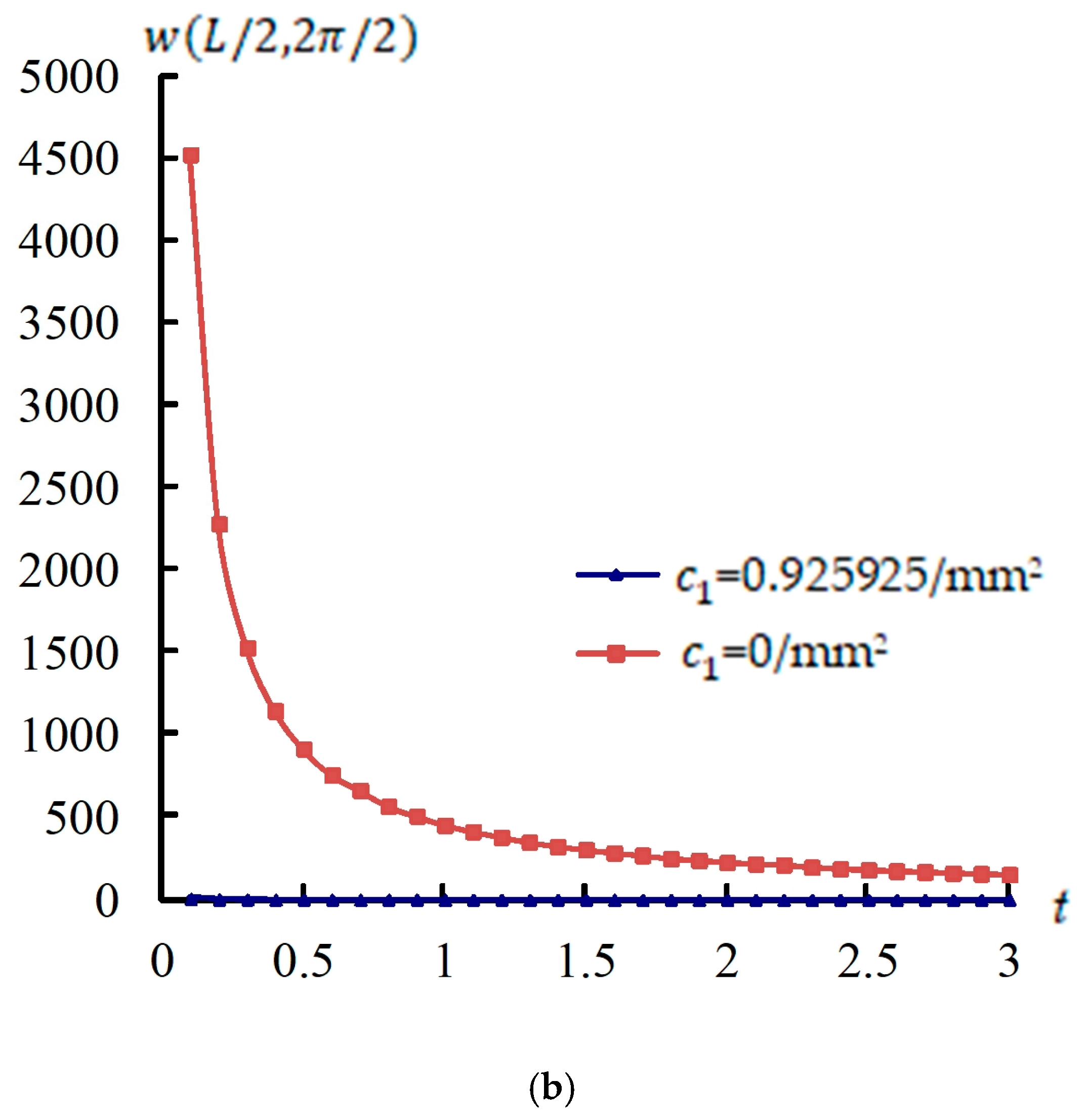
w ( L / 2,2 π / 2 ) (mm) time responses with respect to the TSDT and FSDT are presented. Figure 2 shows w ( L / 2,2 π / 2 ) (mm) versus t(s) of the TSDT case with values c 1 = 0.925925/mm2, k α = –3.535402, and the FSDT case with values c 1 = 0, k α = 1.200860 for L / h * = 5 and 10, respectively, R n = 1, T = 600 K, T ¯ 1 = 100 K, and period t = 0.1 s–3.0 s. The w ( L / 2,2 π / 2 ) maximum value is 36.596103 mm obtained at t = 0.5 s, L / h * = 5, c 1 = 0/mm2, and γ = 3.141593/s, as shown in Figure 2a. The w ( L / 2,2 π / 2 ) value first jumps then shows a decreasing tendency vs. time for c 1 = 0.925925/mm2, also decreasing vs. time for c 1 = 0/mm2, L / h * = 5. The maximum value of w ( L / 2,2 π / 2 ) is 4520.717 mm, obtained at t = 0.1 s, L / h * = 10, c 1 = 0/mm2, and γ = 15.707963/s, as shown in Figure 2b. w ( L / 2,2 π / 2 ) values decrease vs. time for both c 1 = 0.925925/mm2 and c 1 = 0/mm2 in L / h * = 10. w ( L / 2,2 π / 2 ) values in linear c 1 = 0/mm2 are overestimated and bigger than the nonlinear c 1 = 0.925925/mm2 in L / h * = 10, e.g., the value 153.042 mm in the c 1 = 0/mm2 case is much greater than 0.207166 mm in the c 1 = 925925/mm2 case at t = 3.0 s.

3.5. Stresses Time Responses

The σ x and σ x θ values usually vary through the thickness direction of circular cylindrical shells, as displayed in Figure 3 for the compared accuracy of the present approach with advanced k α and non-advanced k α , respectively. Figure 3a displays σ x (GPa) vs.   z / h * , and Figure 3b displays σ x θ (GPa) vs. z / h * on x = L/2, θ = 2 π / 2 , respectively, at t = 3.0 s,   a / h * = 10,   c 1 = 0.925925/mm2 for advanced k α , and c 1 = 0 for non-advanced k α , R n = 1. The 0.0016675 GPa value of σ x at z = –0.5 h * is obtained and bigger than the 0.00024443 GPa value of σ x θ at z = 0.5 h * , so stress σ x can be considered as being dominant in the advanced k α case. Figure 3c–d display σ x (GPa) time responses at z = –0.5 h * ,   c 1 = 0.925925/mm2 for advanced k α , and c 1 = 0 for non-advanced k α , R n = 1, L / h * = 5, 10, respectively. The σ x maximum value is 0.0017718 GPa for the advanced k α case obtained at t = 0.1 s during periods t = 0.1 s–3 s, L / h * = 5, as shown in Figure 3c. The values of σ x have a smoothly decreasing tendency with time in the case of c 1 = 0.925925/mm2 for advanced k α and c 1 = 0 for non-advanced k α , L / h * = 5. σ x values are linearly decreasing vs. time for c 1 = 0.925925/mm2 for advanced k α and c 1 = 0 for non-advanced k α , L / h * = 10, as shown in Figure 3d. The values of σ x and σ x θ with advanced k α are smaller than those with non-advanced k α .

3.6. Compared Results

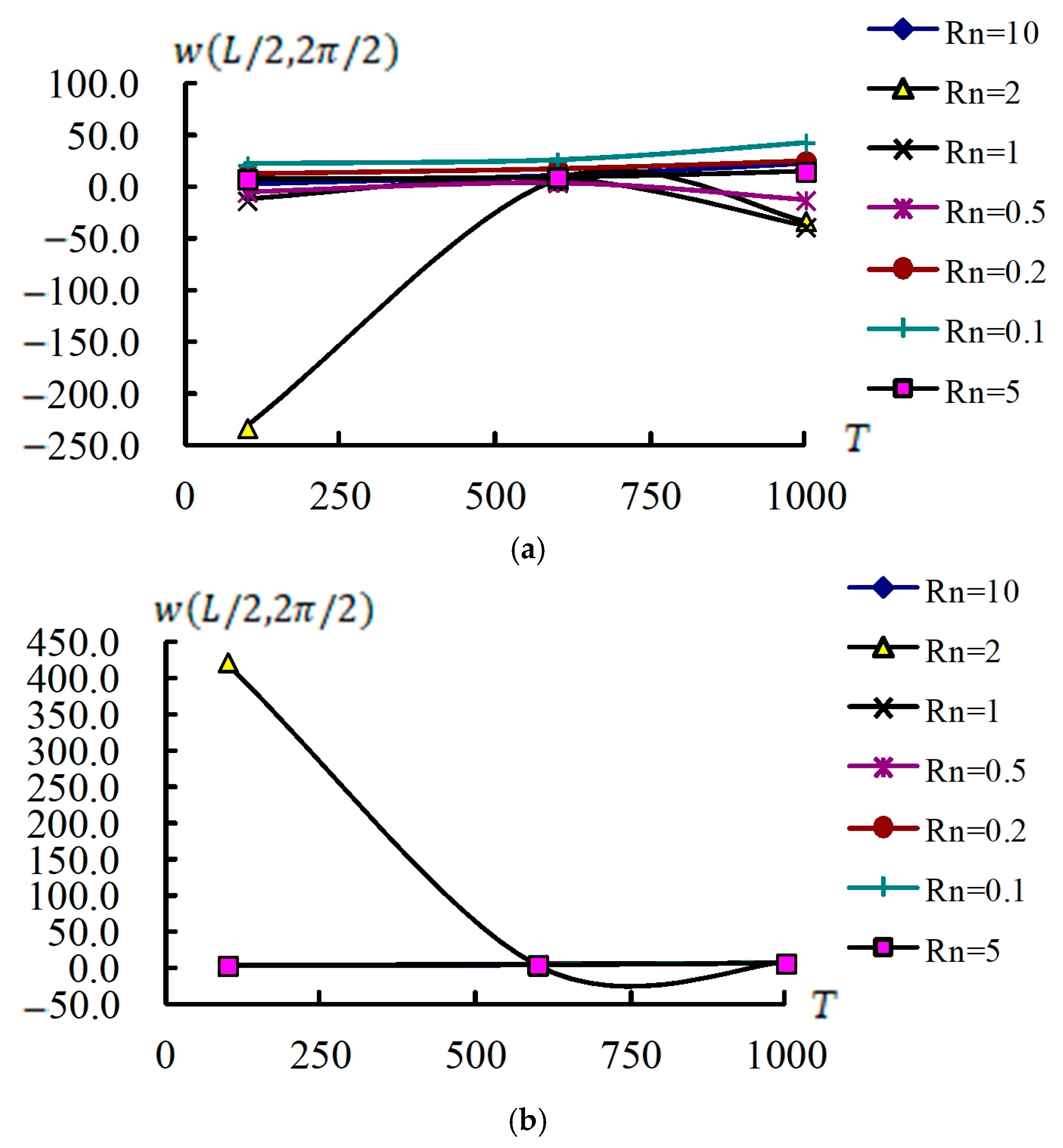
Figure 4 displays w ( L / 2,2 π / 2 ) (mm) responses vs. T(K) of values 100 K, 600 K, and 1000 K for R n = 0.1 to 10 under c 1 = 0.925925/mm2 for L / h * = 5, 10, respectively, T ¯ 1 = 100 K at t = 0.1 s. Figure 4a displays w ( L / 2,2 π / 2 ) curves vs. T and R n in L / h * = 5. The w ( L / 2,2 π / 2 ) maximum value is −233.119 mm obtained at T = 100 K for R n = 2. w ( L / 2,2 π / 2 ) values are increasing vs. T = 100 K to 1000 K, for R n values except R n = 2. Thus, w ( L / 2,2 π / 2 ) in L / h * = 5 cannot withstand T = 1000 K. Figure 4b displays the same w ( L / 2,2 π / 2 ) curve vs. T and R n in L / h * = 10, except R n = 2. The w ( L / 2,2 π / 2 ) maximum value is 422.436 mm obtained at T = 100 K for all values of R n . w ( L / 2,2 π / 2 ) increases vs. T except for R n = 2. Thus, w ( L / 2,2 π / 2 ) in L / h * = 10 also cannot withstand T = 1000 K at t = 0.1 s.
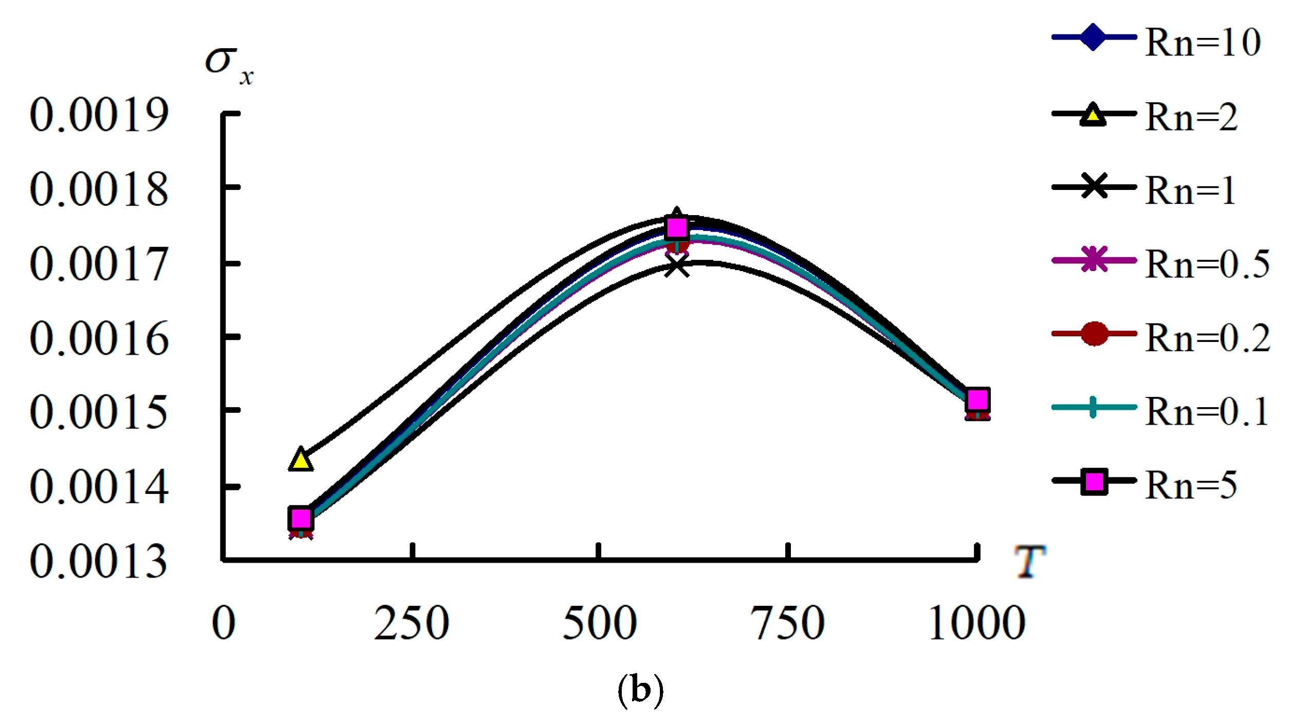
Figure 5 displays σ x (GPa) at z = –0.5 h * vs. T and R n , L / h * = 5 and 10. Figure 5a displays σ x curves vs. T, R n in L / h * = 5. σ x is an increasing value vs. T = 100 K to 600 K, then decreases vs. T = 600 K to 1000 K. The σ x maximum value is 0.001838 GPa obtained at T = 600 K, R n = 0.5. Thus σ x in L / h * = 5 can withstand T = 1000 K. Figure 5b shows the same curve of σ x vs. T and R n in L / h * = 10 for all R n . σ x is an increasing value versus T = 100 K to 600 K, then a decreasing value versus T = 600 K to 1000 K for all R n . The σ x maximum value is 0.001759 GPa obtained at T = 600 K, R n = 2. Thus σ x in L / h * = 10 also can withstand T = 1000 K at t = 0.1 s.
Transient responses of w ( L / 2,2 π / 2 ) (mm) are presented in Figure 6 for c 1 = 0.925925/mm2, L / h * = 10, and fixed ω 11 = 0.008380/s; also used are R n = 1, k α = –3.535402, T = 600 K, and T ¯ 1 = 100 K for period t = 0.001 s–0.025 s. Figure 6a displays the advanced w ( L / 2,2 π / 2 ) comparisons with super value γ = 284314.1/s and high value γ = 785.3982/s. w ( L / 2,2 π / 2 ) vs. higher γ has greater oscillations and decreasing values. Figure 6b displays the w ( L / 2,2 π / 2 ) comparisons with lower values γ = 15.707963/s and γ = 0.523599/s. The transient values of w ( L / 2,2 π / 2 ) vs. lower γ are all rapid converging. Figure 6c displays the comparison of the available displacement w(a/2,b/2) (m) by Lee et al. published in 2004 [24]. The good tendency of transient responses shows the accuracy in γ = 284314.1/s oscillations for the presented approach.

4. Conclusions

The thermal displacements and stresses of GDQ solutions are presented in the nonlinear TSDT vibration and advanced varied shear correction coefficient for composited FGM thick circular cylindrical shells. Another important parameter for the advanced nonlinear varied shear factor is also studied using the approach of a fully homogeneous frequency equation and nonlinear c 1 in the TSDT. Displacement values in the linear FSDT c 1 = 0/mm2 are overestimated with respect to the nonlinear TSDT c 1 = 0.925925/mm2 for L / h * = 10. The σ x value decreases linearly vs. time in the TSDT c 1 = 0.925925/mm2 for L / h * = 10. w ( L / 2,2 π / 2 ) in R n = 2, L / h * = 5 and 10 cannot withstand T = 1000 K. σ x in all R n , L / h * = 5 and 10 can withstand T = 1000 K at t = 0.1 s. The main findings of this study are listed as follows: (a) The grids N × M = 13 × 13 of GDQ computations are in a convergence state at t = 6 s for thick FGM circular cylindrical shells. (b)   w ( L / 2,2 π / 2 ) values decrease vs. time for both c 1 = 0.925925/mm2 and c 1 = 0/mm2 in L / h * = 10. (c) w ( L / 2,2 π / 2 ) values in the FSDT linear c 1 = 0/mm2 are overestimated and bigger than those in the TSDT nonlinear c 1 = 0.925925/mm2 in the L / h * = 10. (d) The values of σ x decrease with time for L / h * = 5 and 10. The values of σ x and σ x θ with advanced k α are smaller than those with non-advanced k α . (e) w ( L / 2,2 π / 2 ) , except for R n = 2, L / h * = 5 and 10 can withstand T = 1000 K. (f) σ x for all R n , L / h * = 5 and 10, can withstand T = 1000 K. (g) The transient values of w ( L / 2,2 π / 2 ) vs. higher γ have greater oscillations and are decreasing. w ( L / 2,2 π / 2 ) vs. lower γ are all rapid converging.

Funding

This research received no external funding.

Data Availability Statement

The original contributions presented in the study are included in the article, further inquiries can be directed to the corresponding authors.

Acknowledgments

The author expresses his thanks to the people helping with this work, and acknowledges the valuable suggestions from the peer reviewers.

Conflicts of Interest

The author declares no conflicts of interest.

Appendix A

The dynamic equilibrium PDE of the TSDT in composited FGM cylindrical shells can be derived as follows:
0 0 0 0 0 0 0 0 0 0 c 1 2 H 11 4 c 1 2 H 16 2 c 1 2 H 12 4 c 1 2 H 66 4 c 1 2 H 26 c 1 2 H 22 0 0 0 0 0 0 0 0 0 0
4 w x 4 1 R 4 w x 3 θ 1 R 2 4 w x 2 θ 2 1 R 3 4 w x θ 3 1 R 4 4 w θ 4 t
+ 0 0 0 0 0 0 0 0 c 1 E 11 3 c 1 E 16 c 1 E 12 2 c 1 E 66 c 1 E 26 0 0 0 0 0 0 0 0 c 1 E 16 c 1 E 12 2 c 1 E 66 3 c 1 E 26 c 1 E 22 c 1 E 11 3 c 1 E 16 c 1 E 12 + 2 c 1 E 66 c 1 E 26 c 1 E 16 c 1 E 12 + 2 c 1 E 66 3 c 1 E 26 c 1 E 22 0 0 0 0 0 0 0 0 0 0 0 0 c 1 F 11 + c 1 2 H 11 3 c 1 F 16 + 3 c 1 2 H 16 c 1 F 12 + c 1 2 H 12 2 c 1 F 66 + 2 c 1 2 H 66 c 1 F 26 + c 1 2 H 26 0 0 0 0 0 0 0 0 c 1 F 16 + c 1 2 H 16 2 c 1 F 66 + 2 c 1 2 H 66 c 1 F 12 + 2 c 1 2 H 12 3 c 1 F 26 + 3 c 1 2 H 26 c 1 F 22 + c 1 2 H 22
3 u 0 x 3 1 R 3 u 0 x 2 θ 1 R 2 3 u 0 x θ 2 1 R 3 3 u 0 θ 3 3 v 0 x 3 1 R 3 v 0 x 2 θ 1 R 2 3 v 0 x θ 2 1 R 3 3 v 0 θ 3 3 w x 3 1 R 3 w x 2 θ 1 R 2 3 w x θ 2 1 R 3 3 w θ 3 t
+ 0 0 0 0 0 0 0 0 0 0 0 0 0 0 0 0 c 1 F 11 c 1 2 H 11 3 c 1 F 16 3 c 1 2 H 16 2 c 1 F 66 2 c 1 2 H 66 + c 1 F 12 c 1 2 H 12 c 1 F 26 c 1 2 H 26 c 1 F 16 c 1 2 H 16 c 1 F 12 c 1 2 H 12 + 2 c 1 F 66 2 c 1 2 H 66 3 c 1 F 26 3 c 1 2 H 26 c 1 F 22 c 1 2 H 22 0 0 0 0 0 0 0 0 0 0 0 0 0 0 0 0
3 ϕ x x 3 1 R 3 ϕ x x 2 θ 1 R 2 3 ϕ x x θ 2 1 R 3 3 ϕ x θ 3 3 ϕ θ x 3 1 R 3 ϕ θ x 2 θ 1 R 2 3 ϕ θ x θ 2 1 R 3 3 ϕ θ θ 3 t
+ A 11 2 A 16 A 66 A 16 A 12 + A 66 A 26 0 0 0 A 16 A 12 + A 66 A 26 A 66 2 A 26 A 22 0 0 0 0 0 0 0 0 0 3 c 1 ( 2 D 55 3 c 1 F 55 ) + A 55 + c 1 2 I 6 2 t 2 6 c 1 ( 2 D 45 3 c 1 F 45 ) + 2 A 45 3 c 1 ( 2 D 44 3 c 1 F 44 ) + A 44 + c 1 2 I 6 2 t 2 B 11 c 1 E 11   2 B 16 2 c 1 E 16   B 66 c 1 E 66   B 16 c 1 E 16   B 12 + B 66 c 1 E 12 c 1 E 66   B 26 c 1 E 26   0 0 0 B 16 c 1 E 16 B 12 + B 66 c 1 E 12 c 1 E 66 B 26 c 1 E 26 B 66 c 1 E 66 2 B 26 2 c 1 E 26 B 22 c 1 E 22 0 0 0
2 u 0 x 2 1 R 2 u 0 x θ 1 R 2 2 u 0 θ 2 2 v 0 x 2 1 R 2 v 0 x θ 1 R 2 2 v 0 θ 2 2 w x 2 1 R 2 w x θ 1 R 2 2 w θ 2 t
+ B 11 c 1 E 11 2 B 16 2 c 1 E 16 B 66 c 1 E 66 B 16 c 1 E 16 B 12 + B 66 c 1 E 12 c 1 E 66 B 26 c 1 E 26 B 16 c 1 E 16 B 12 + B 66 c 1 E 12 c 1 E 66 B 26 c 1 E 26 B 66 c 1 E 66 2 B 26 2 c 1 E 26 B 22 c 1 E 22 0 0 0 0 0 0 D 11 2 c 1 F 11 + c 1 2 H 11 2 D 16 4 c 1 F 16 + 2 c 1 2 H 16 D 66 2 c 1 F 66 + c 1 2 H 66 D 16 2 c 1 F 16 + c 1 2 H 16 D 12 + D 66 2 c 1 F 12 + c 1 2 H 12 2 c 1 F 66 + c 1 2 H 66 D 26 2 c 1 F 26 + c 1 2 H 26 D 16 2 c 1 F 16 + c 1 2 H 16 D 12 + D 66 2 c 1 F 12 + c 1 2 H 12 2 c 1 F 66 + c 1 2 H 66 D 26 2 c 1 F 26 + c 1 2 H 26 D 66 2 c 1 F 66 + c 1 2 H 66 2 D 26 4 c 1 F 26 + 2 c 1 2 H 26 D 22 2 c 1 F 22 + c 1 2 H 22
2 ϕ x x 2 1 R 2 ϕ x x θ 1 R 2 2 ϕ x θ 2 2 ϕ θ x 2 1 R 2 ϕ θ x θ 1 R 2 2 ϕ θ θ 2 t
0 0 0 0 c 1 I 3 2 t 2 0 0 0 0 0 0 0 0 0 0 c 1 I 3 2 t 2 0 0 0 0 c 1 I 3 2 t 2 u 0 R ( A 55 3 c 1 D 55 ) u 0 R ( A 45 3 c 1 D 45 ) v 0 R ( A 45 3 c 1 D 45 ) c 1 I 3 2 t 2 v 0 R ( A 44 3 c 1 D 44 ) 0 0 A 55 6 c 1 D 55 + 9 c 1 2 F 55 c 1 J 4 2 t 2 A 45 6 c 1 D 45 + 9 c 1 2 F 45 A 45 6 c 1 D 45 + 9 c 1 2 F 45 A 44 6 c 1 D 44 + 9 c 1 2 F 44 c 1 J 4 2 t 2 0 0 0 0 6 c 1 D 55 9 c 1 2 F 55 A 55 + c 1 J 4 2 t 2 6 c 1 D 45 9 c 1 2 F 45 A 45 0 0 0 0 0 0 0 0 6 c 1 D 45 9 c 1 2 F 45 A 45 6 c 1 D 44 9 c 1 2 F 44 A 44 + c 1 J 4 2 t 2 0 0 0 0 u 0 x 1 R u 0 θ v 0 x 1 R v 0 θ w x 1 R w θ ϕ x x 1 R ϕ x θ ϕ θ x 1 R ϕ θ θ t
+ I 0 2 t 2 0 0 J 1 2 t 2 0 0 I 0 2 t 2 0 0 J 1 2 t 2 0 0 I 0 2 t 2 0 0 J 1 2 t 2 1 R ( A 55 + 3 c 1 D 55 ) 1 R ( A 45 + 3 c 1 D 45 ) 0 A 55 + 6 c 1 D 55 9 c 1 2 F 55 K 2 2 t 2 A 45 + 6 c 1 D 45 9 c 1 2 F 45 1 R ( A 45 + 3 c 1 D 45 ) J 1 2 t 2 1 R ( A 44 + 3 c 1 D 44 ) 0 A 45 + 6 c 1 D 45 9 c 1 2 F 45 A 44 + 6 c 1 D 44 9 c 1 2 F 44 K 2 2 t 2 u 0 v 0 w ϕ x ϕ θ
= f 1 f 2 f 3 f 4 f 5 ,
in which f 1 = N ¯ x x x + 1 R N ¯ x θ θ + p 1 , f 2 = N ¯ x θ x + 1 R N ¯ θ θ θ + p 2 ,
f 3 = q + c 1 ( 2 P ¯ x x x 2 + 2 R 2 P ¯ x θ x θ + 1 R 2 2 P ¯ θ θ θ 2 ) ,
f 4 = M ¯ ˜ x x x + 1 R M ¯ ˜ x θ θ c 1 ( P ¯ x x x + 1 R P ¯ x θ θ ) ,
f 5 = M ¯ ˜ x θ x + 1 R M ¯ ˜ θ θ θ c 1 ( P ¯ x θ x + 1 R P ¯ θ θ θ ) ,
( N ¯ x x , M ¯ ˜ x x , P ¯ x x ) = h * 2 h * 2 ( Q ¯ 11 α x + Q ¯ 12 α θ + Q ¯ 16 α x θ ) Δ T ( 1 , z , z 3 ) d z ,
( N ¯ θ θ , M ¯ ˜ θ θ , P ¯ θ θ ) = h * 2 h * 2 ( Q ¯ 12 α x + Q ¯ 22 α θ + Q ¯ 26 α x θ ) Δ T ( 1 , z , z 3 ) d z ,
( N ¯ x θ , M ¯ ˜ x θ , P ¯ x θ ) = h * 2 h * 2 ( Q ¯ 16 α x + Q ¯ 26 α θ + Q ¯ 66 α x θ ) Δ T ( 1 , z , z 3 ) d z ,
( A i s j s , B i s j s , D i s j s , E i s j s , F i s j s , H i s j s ) = h * 2 h * 2 Q ¯ i s j s ( 1 , z , z 2 , z 3 , z 4 , z 6 ) d z ,
( A i * j * , B i * j * , D i * j * , E i * j * , F i * j * , H i * j * ) = h * 2 h * 2 k α Q ¯ i * j * ( 1 , z , z 2 , z 3 , z 4 , z 5 ) d z ,
( i s , j s = 1 , 2 , 6 ) ,   ( i * , j * = 4 , 5 ) ,
where p 1 and p 2 denote external forces in x and θ directions. q denotes external pressure. k α denotes the advanced shear coefficient.
Q ¯ i s j s and Q ¯ i * j * are used in simple forms as follows [9]:
Q ¯ 11 = Q ¯ 22 = E f g m 1 ν f g m 2 ,   Q ¯ 12 = Q ¯ 21 = ν f g m E f g m ( 1 + z / R ) ( 1 ν f g m 2 ) ,   Q ¯ 44 = E f g m 2 ( 1 + ν f g m ) ,
Q ¯ 55 = Q ¯ 66 = E f g m 2 ( 1 + z / R ) ( 1 + ν f g m ) ,   Q ¯ 16 = Q ¯ 26 = Q ¯ 45 = 0 ,
where E f g m = ( E 2 E 1 ) ( z + h * / 2 h * ) R n + E 1 , ν f g m = ν 1 + ν 2 2 , where E 1 , E 2 denote Young’s modulus, and ν 1 , ν 2 denote the Poisson ratios for FGM material 1 and material 2. Values for E 1 , E 2 , ν 1 , and ν 2 can be calculated from the P i expression in (1).
The Q ¯ i s j s and Q ¯ i * j * values are also applied to compute σ x , σ θ , σ x θ , σ θ z , σ x z , and stiffness integrals A i s j s , B i s j s , D i s j s , E i s j s , F i s j s , H i s j s , A i * j * , B i * j * , D i * j * , E i * j * , F i * j * , H i * j * , e.g.,
A 11 = h * 1 [ ( ν 1 + ν 2 ) / 2 ] 2 ( R n E 1 + E 2 R n + 1 ) ,
E 11 = ( h * ) 4 ( E 2 E 1 ) 1 [ ( ν 1 + ν 2 ) / 2 ] 2 [ 1 R n + 4 3 2 ( R n + 3 ) + 3 4 ( R n + 2 ) 1 8 ( R n + 1 ) ] , ,
H 44 = k α ( h * ) 6 ( E 2 E 1 ) 2 [ 1 + ( ν 1 + ν 2 ) / 2 ] [ 1 R n + 6 5 2 ( R n + 5 ) + 2 R n + 4 1 R n + 3 + 5 64 ( R n + 2 ) 1 32 ( R n + 1 ) ] .
Also, A 12 , B 12 , D 12 , E 12   F 12 , H 12 , A 55 , B 55 , D 55 , E 55   F 55 , and H 55 in FGM circular cylindrical shells can be obtained, e.g.,
A 12 = ( ν 1 + ν 2 ) / 2 1 [ ( ν 1 + ν 2 ) / 2 ] 2 A E R ,
B 12 = ( ν 1 + ν 2 ) / 2 1 [ ( ν 1 + ν 2 ) / 2 ] 2 B E R , ,
H 55 = k α 2 [ 1 + ( ν 1 + ν 2 ) / 2 ] H E R 5 ,
in which
A E R = ( E 2 E 1 ) R h * R n [ h * R n ( R h * / 2 ) h * R n 1 + ( R h * / 2 ) 2 h * R n 2 ( R h * / 2 ) 3 h * R n 3
+ ( R h * / 2 ) 4 h * R n 4 ] + E 1 R [ ln ( 1 + h * 2 R ) ln ( 1 h * 2 R ) ] ,
B E R = ( E 2 E 1 ) R h * R n { h * R n + 1 ( R h * / 2 ) h * R n + ( R h * / 2 ) 2 h * R n 1 ( R h * / 2 ) 3 h * R n 2
+ ( R h * / 2 ) 4 h * R n 3 h * 2 [ h * R n ( R h * / 2 ) h * R n 1 + ( R h * / 2 ) 2 h * R n 2 ( R h * / 2 ) 3 h * R n 3
+ ( R h * / 2 ) 4 h * R n 4 ] } + E 1 R [ h * R ln ( 1 + h * 2 R ) + R ln ( 1 h * 2 R ) ] ,
H E R 5 = ( E 2 E 1 ) R h * R n { h * R n + 5 ( R h * / 2 ) h * R n + 4 + ( R h * / 2 ) 2 h * R n + 3 ( R h * / 2 ) 3 h * R n + 2
+ ( R h * / 2 ) 4 h * R n + 1 5 h * 2 [ h * R n + 4 ( R h * / 2 ) h * R n + 3 + ( R h * / 2 ) 2 h * R n + 2 ( R h * / 2 ) 3 h * R n + 1
+ + ( R h * / 2 ) 4 h * R n 4 ] } + E 1 R [ h * 5 90 + R 2 h * 3 12 + R 4 h * R 5 ln ( 1 + h * 2 R ) + R 5 ln ( 1 h * 2 R ) ]

References

  1. Shahmohammadi, M.A.; Azhari, M.; Saadatpour, M.M. Free vibration analysis of sandwich FGM shells using isogeometric B-spline finite strip method. Steel Compos. Struct. 2020, 34, 361–376. [Google Scholar]
  2. Hajlaoui, A.; Chebbi, E.; Wali, M.; Dammak, F. Geometrically nonlinear analysis of FGM shells using solid-shell element with parabolic shear strain distribution. Int. J. Mech. Mater. Des. 2020, 16, 351–366. [Google Scholar] [CrossRef]
  3. Ghamkhar, M.; Naeem, M.N.; Imran, M.; Kamran, M.; Soutis, C. Vibration frequency analysis of three-layered cylinder shaped shell with effect of FGM central layer thickness. Sci. Rep. 2019, 9, 1566. [Google Scholar] [CrossRef] [PubMed]
  4. Moshkelgosha, E.; Askari, E.; Jeong, K.H.; Shafiee, A.A. Fluid-structure coupling of concentric double FGM shells with different lengths. Struct. Eng. Mech. 2017, 61, 231–244. [Google Scholar] [CrossRef]
  5. Hajlaoui, A.; Triki, E.; Frikha, A.; Wali, M.; Dammak, F. Nonlinear dynamics analysis of FGM shell structures with a higher order shear strain enhanced solid-shell element. Lat. Am. J. Solids Struct. 2017, 14, 72–91. [Google Scholar] [CrossRef]
  6. Golpayegani, I.F.; Arani, E.M.; Foroughifar, A.A. Finite element vibration analysis of variable thickness thin cylindrical FGM shells under various boundary conditions. ASTM Int. 2019, 8, 491–502. [Google Scholar] [CrossRef]
  7. Singh, R.; Sharma, P. A review on modal characteristics of FGM structures. AIP Conf. Proc. 2019, 2148, 030037. [Google Scholar]
  8. Tornabene, F.; Reddy, J.N. FGM and laminated doubly-curved and degenerate shells resting on nonlinear elastic foundations: A GDQ solution for static analysis with a posteriori stress and strain recover. J. Indian Inst. Sci. 2013, 93, 635–688. [Google Scholar]
  9. Sepiani, H.A.; Rastgoo, A.; Ebrahimi, F.; Arani, A.G. Vibration and buckling analysis of two-layered functionally graded cylindrical shell considering the effects of transverse shear and rotary inertia. Mater. Des. 2010, 31, 1063–1069. [Google Scholar] [CrossRef]
  10. Reddy, J.N. Book chapter 10—Free vibration analysis of functionally graded ceramic-metal plates. In Analysis and Design of Plated Structures; Series in Civil and Structural Engineering; Woodhead Publishing: Sawston, UK, 2007; Volume 1, pp. 293–321. [Google Scholar] [CrossRef]
  11. Rafieea, M.; Nitzscheb, F.; Labrosse, M. Dynamics, vibration and control of rotating composite beams and blades: A critical review. Thin-Walled Struct. 2017, 119, 795–819. [Google Scholar] [CrossRef]
  12. Kazancı, Z. A review on the response of blast loaded laminated composite plates. Prog. Aerosp. Sci. 2016, 81, 49–59. [Google Scholar] [CrossRef]
  13. Teotia, M.; Soni, R.K. Applications of finite element modelling in failure analysis of laminated glass composites: A review. Eng. Fail. Anal. 2018, 94, 412–437. [Google Scholar] [CrossRef]
  14. D’Ottavio, M.; Polit, O. Book chapter 3—Classical, first order, and advanced theories. In Stability and Vibrations of Thin Walled Composite Structures; Woodhead Publishing: Sawston, UK, 2017; pp. 91–140. [Google Scholar]
  15. Sobhani Aragh, B.; Borzabadi Farahani, E.; Xu, B.X.; Ghasemnejad, H.; Mansur, W.J. Manufacturable insight into modelling and design considerations in fibre-steered composite laminates: State of the art and perspective. Comput. Methods Appl. Mech. Eng. 2021, 379, 113752. [Google Scholar] [CrossRef]
  16. Birman, V.; Genin, G.M. Book chapter 1.15 Linear and nonlinear elastic behavior of multidirectional laminates. In Comprehensive Composite Materials II; Elsevier: Amsterdam, The Netherlands, 2018; Volume 1, pp. 376–398. [Google Scholar] [CrossRef]
  17. Thai, H.T.; Kim, S.E. A review of theories for the modeling and analysis of functionally graded plates and shells. Compos. Struct. 2015, 128, 70–86. [Google Scholar] [CrossRef]
  18. Paroissien, E.; Lachaud, F.; Schwartz, S. Modelling load transfer in single-lap adhesively bonded and hybrid (bolted/bonded) joints. Prog. Aerosp. Sci. 2022, 130, 100811. [Google Scholar] [CrossRef]
  19. Kurpa, L.; Shmatko, T. Book chapter 11—Parametric vibrations of axially compressed functionally graded sandwich plates with a complex plan form. In Mechanics and Physics of Structured Media; Academic Press: Cambridge, MA, USA, 2022; pp. 213–232. [Google Scholar] [CrossRef]
  20. Banić, D.; Turkalj, G.; Lanc, D. A geometrically nonlinear finite element formulation for buckling analysis of shear deformable angle-ply composite beam-type structures. Comput. Struct. 2024, 301, 107427. [Google Scholar] [CrossRef]
  21. Benounas, S.; Belarbi, M.O.; Vinh, P.V.; Daikh, A.A.; Fantuzzi, N. Finite element model for free vibration analysis of functionally graded doubly curved shallow shells by using an improved first-order shear deformation theory. Structures 2024, 64, 106594. [Google Scholar] [CrossRef]
  22. Thu, T.T.T.; Anh, T.N.; Thi, H.N.; Thi, H.N. Transient response of doubly-curved bio-inspired composite shells resting on viscoelastic foundation subject to blast load using improved first-order shear theory and isogeometric approach. Def. Technol. 2024, 38, 171–193. [Google Scholar] [CrossRef]
  23. Hong, C.C. Thermal vibration of thick FGM spherical shells by using TSDT. Int. J. Mech. Mater. Des. 2021, 17, 367–380. [Google Scholar] [CrossRef]
  24. Lee, S.J.; Reddy, J.N.; Rostam-Abadi, F. Transient analysis of laminated composite plates with embedded smart-material layers. Finite Elem. Anal. Des. 2004, 40, 463–483. [Google Scholar] [CrossRef]
  25. Hong, C.C. Advanced frequency of thick FGM cylindrical shells with fully homogeneous equation. J. Struct. Eng. Appl. Mech. 2024, 7, 69–83. [Google Scholar] [CrossRef]
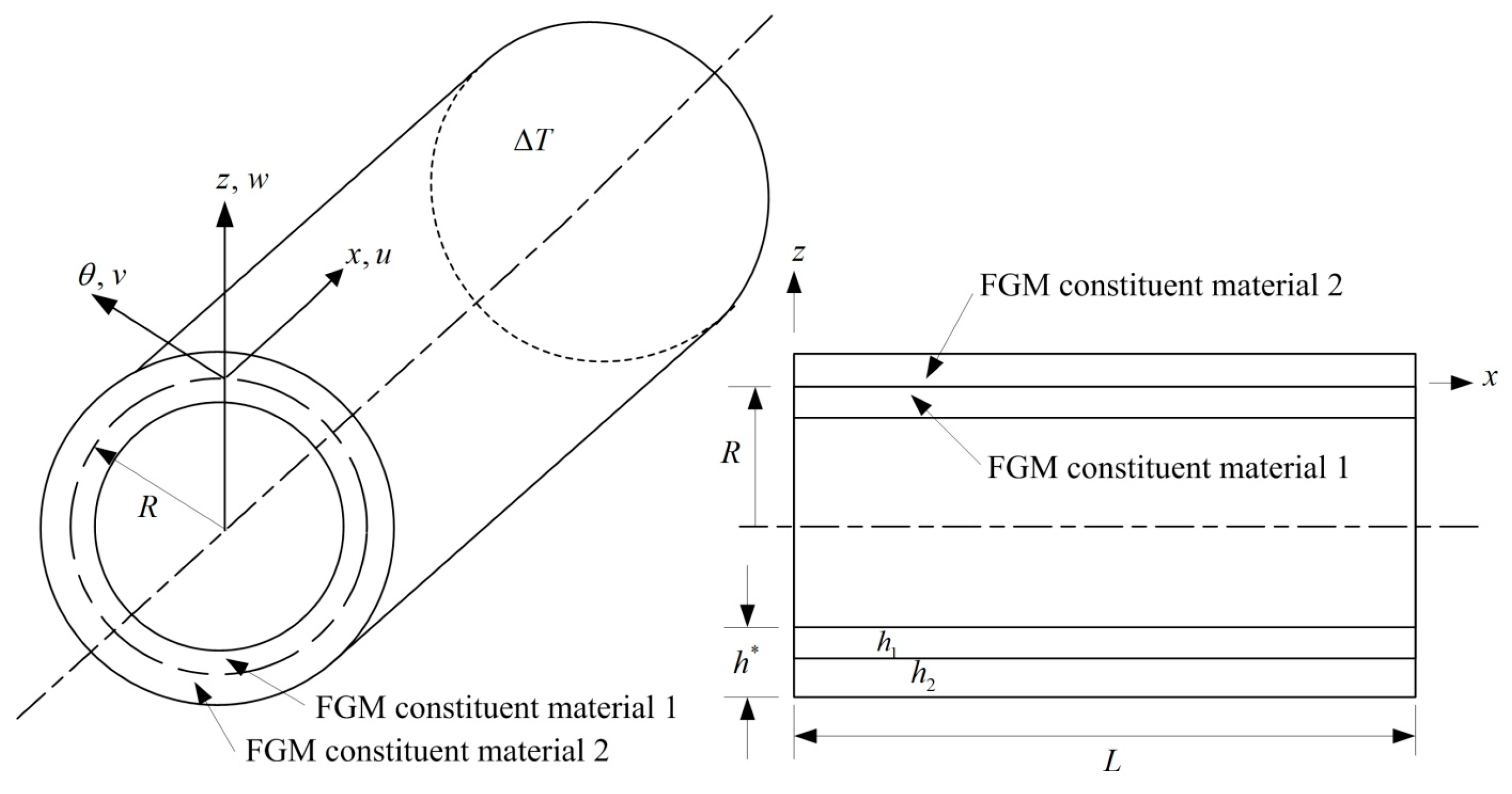
Figure 1. Constituent materials of composite FGM cylindrical shells under T .
Jcs 09 00004 g001
Figure 2. Advanced w ( L / 2,2 π / 2 ) (mm) vs. t(s) for: (a) L / h * = 5; (b) L / h * = 10.
Jcs 09 00004 g002aJcs 09 00004 g002b
Figure 3. Comparisons of stresses (GPa) versus z / h * and t(s) with advanced k α and non-advanced k α for: (a)   σ x vs. z / h * of L / h * = 10; (b) σ x θ vs.   z / h * of L / h * = 10; (c) σ x vs. t of L / h * = 5; (d) σ x vs. t of L / h * = 10 .
Jcs 09 00004 g003aJcs 09 00004 g003b
Figure 4. Advanced w ( L / 2,2 π / 2 ) (mm) vs. T(K), R n = 0.1 to 10 for: (a) L / h * = 5; (b)   L / h * = 10.
Jcs 09 00004 g004
Figure 5. Advanced σ x (GPa) versus T(K) for: (a) L / h * = 5; (b) L / h * = 10.
Jcs 09 00004 g005aJcs 09 00004 g005b
Figure 6. Advanced transient responses of w ( L / 2,2 π / 2 ) (mm) vs. t(s) of L / h * = 10 for: (a) γ = 284314.1/s and 785.3982/s; (b) γ = 15.707963/s and 0.523599/s. (c) Comparison with displacement w(a/2,b/2) (m) by Lee et al. published in 2004 [24].
Jcs 09 00004 g006aJcs 09 00004 g006b
Table 1. FGM cylindrical shells’ convergence with fully homogeneous eq., advanced k α .
c 1 (1/mm2) L / h * GDQ Grids w ( L / 2,2 π / 2 ) (mm) at t = 6 s
N × M R n = 0.5 R n = 1 R n = 2
0.925925107 × 74.7765844.6426888.262124
9 × 94.7714514.6380218.254965
11 × 114.7714574.6380098.255040
13 × 134.7715664.6380398.254931
57 × 70.4984780.4639562.032378
9 × 90.4980310.4635652.030849
11 × 110.4980310.4635682.030760
13 × 130.4980260.4635622.030836
0107 × 7475.2319412.1400421.1254
9 × 961.3065764.7135965.75298
11 × 1162.1506063.5956766.56091
13 × 1361.3429964.7532365.77515
57 × 72.5386222.6641052.716292
9 × 92.4222372.5555002.597797
11 × 112.4225142.5557242.598066
13 × 132.4225252.5557302.598067
Disclaimer/Publisher’s Note: The statements, opinions and data contained in all publications are solely those of the individual author(s) and contributor(s) and not of MDPI and/or the editor(s). MDPI and/or the editor(s) disclaim responsibility for any injury to people or property resulting from any ideas, methods, instructions or products referred to in the content.