Technical Note

A Comparative Study of Airbag Covers for Automotive Safety Using Coconut Shell Fiber/PP Composite Materials

Mechanical and Electrical Engineering College, Hainan University, Haikou 570228, China
*
Author to whom correspondence should be addressed.
J. Compos. Sci. 2024, 8(8), 328; https://doi.org/10.3390/jcs8080328
Submission received: 7 July 2024 / Revised: 9 August 2024 / Accepted: 13 August 2024 / Published: 19 August 2024
(This article belongs to the Topic Advanced Composites Manufacturing and Plastics Processing)

Abstract

:
In this study, we compared the physical properties of coconut fiber/polypropylene (PP) composite materials with coconut fiber as a reinforcing agent, produced through a hybrid injection molding process and a layered hot-pressing process. Through comparative experiments, the mechanical properties of both the hybrid injection-molded and layered hot-pressed materials were validated. The results indicated that, when using a coconut fiber content of 5%, the layered hot-pressed composite material exhibited optimal comprehensive performance. Specifically, its tensile strength reached 25.12 MPa, showing a 37.6% increase over that of pure PP materials of the same brand and batch. Its tensile modulus was 1.17 GPa, representing an 11.4% decrease. Additionally, its bending strength was 35.94 MPa, marking a 49.8% increase, and its bending modulus was 2.69 GPa, which is nearly double that of pure PP materials. Furthermore, through Creo modeling and an ANSYS simulation analysis, it was verified that this material could be applied to airbag covers in the field of automotive safety. This study confirmed that layered hot-pressed coconut fiber/PP composite materials exhibit superior mechanical properties to traditional materials and injection-molded composite materials, making them more suitable for airbag covers.

1. Introduction

With the rapid development of the automotive industry, there is an increasing demand for lightweight and safe vehicles [1,2]. In this context, fiber-reinforced materials have become indispensable in the automotive industry due to their excellent mechanical properties and lightweight characteristics. Notably, natural plant fibers have attracted significant attention as reinforcing materials in automotive components due to their renewable and environmentally friendly characteristics, [3,4,5,6,7,8]. Traditionally, synthetic fibers such as glass fiber and aramid fiber have been widely used in automotive manufacturing. However, these materials do have disadvantages, such as high costs, associated environmental pollution, and limited raw material resources for their production and recycling. To address these issues, researchers have begun exploring the use of natural plant fibers, such as coconut shell fiber, as alternative materials. Coconut shell fiber is not only abundant and cost-effective but also possesses excellent mechanical properties and thermal stability, making it an ideal choice for reinforcing automotive interior components [9,10,11,12,13,14,15,16].
Coconut shell fiber, a type of cellulose fiber, has a multi-cellular aggregation structure and contains a high proportion of lignin and cellulose. These components confer unique chemical and physical properties to coconut shell fiber, including good heat resistance and high elongation at break [17,18,19,20,21]. These characteristics make coconut shell fiber a highly promising material for the reinforcement of polypropylene (PP) materials, particularly in applications such as automotive airbag covers [22]. Despite the broad prospects of coconut shell fiber for application in composite materials, challenges remain in terms of interface bonding with the PP matrix, uniform dispersion, and processing techniques for the composites [23,24,25,26,27,28,29,30]. Traditional injection molding and emerging layer-by-layer hot-pressing methods each have their advantages in preparing coconut shell fiber/PP composites. This study aimed to explore the impact of different processing methods on the physical properties of composites by comparing the two techniques and evaluating their feasibility in the production of automotive airbag covers.
The purpose of this study was to present safer, lighter, and more cost-effective alternative materials for the production of automotive airbag covers through comprehensively considering their environmental friendliness, cost-effectiveness, and performance. Through in-depth research on coconut shell fiber/PP composites, we hope to contribute to the sustainable development of the automotive industry and promote the application of environmentally friendly materials in a wider range of fields.

2. Materials and Methods

2.1. Primary Materials

Coconut shell fibers, either with lengths of 120–140 mm or 3–5 mm, or in powder form, were sourced from Hainan, China. Polypropylene (PP), grade PP-BG2017F, was supplied by Nanjing Julong Technology Co., Ltd., Nanjing, China. Different chemical reagents were used to treat the coconut fibers: sodium hydroxide, of analytical grade, supplied by China National Pharmaceutical Group Corporation (Beijing, China); anhydrous ethanol, of analytical grade, supplied by China National Pharmaceutical Group Corporation; and coupling agent KH550, of industrial grade, supplied by Shandong Jinan Guanhe Chemical Co., Ltd., Jinan, China.

2.2. Instruments and Equipment

A stainless-steel crusher ZG-J210H (Ningbo Zhaoji Electric Appliance Co., Ltd., Ningbo, China.) was used to cut coconut shell fibers into lengths of 3–5 mm. The treated fibers were dried at a constant temperature in an electric blast-drying oven (101-00B, Shaoxing Huyue Instrument Equipment Co., Ltd., Shaoxing, China.). We used a plastic injection molding machine CJ150M3V, supplied by Dongguan Aiyufa Automation Machinery Co., Ltd., Dongguan, China. which was further equipped with an injection mold provided by Kunshan Yushan Town Oubaijia Testing Instrument Business Department (Kunshan, China) and used to manufacture the short fiber-reinforced composite samples. A hot press-molding machine, HH-100A is provided by Huahui Hydraulic Machinery Factory in Dongguan, China, and is equipped with a hot pressing mold provided by the Oubaijia Testing Instrument Division in Yushan Town, Kunshan City, China, for the manufacture of long fiber reinforced composite material samples. The mechanical properties of the manufactured composite samples were measured using an electronic universal testing machine, KQL WD7-5, from Shenzhen Kaiqiangli Experimental Instrument Co., Ltd., Shenzhen, China. which was equipped with an extensometer to record strain during tensile tests.

2.3. Sample Preparation

2.3.1. Alkali Treatment of Coconut Shell Fiber

For the surface treatment of coconut shell fibers, we pretreated fibers with lengths of 120–140 mm and 3–5 mm and fibers in powder form by washing away impurities and air-drying them at room temperature. We then submerged the cleaned and dried coconut shell fibers in a 5% concentration (mass fraction) NaOH solution for 15 h before filtering. We thoroughly rinsed the alkali-treated coconut shell fibers with distilled water to ensure that no NaOH residue remained before air-drying at room temperature and further drying at a constant temperature of 90 °C in an electric blast-drying oven for 5 h.

2.3.2. Coupling Agent Treatment of Coconut Shell Fibers

For the preparation of the coupling agent, we placed the alkali-treated coconut shell fiber in a 5% concentration KH550 ethanol solution, let it stand for 1 h, and then filtered it. We air-dried the mixture at room temperature and further dried it in an electric blast-drying oven at a constant temperature of 90 °C for 5 h. The pretreatment of coconut shell fiber was thus completed.

2.3.3. Preparation of Coconut Shell Fiber/PP Composite Material Specimens

During this experiment, we prepared two types of coconut shell fiber/PP composite material specimens with different fiber lengths and arrangements and one specimen of pure PP material. They may be described as follows:
  • Cross-arranged stacked hot-pressed coconut shell fiber/PP composite-material specimens with lengths of 120–140 mm were processed using a hot press-molding machine to form 1 mm thick sheets of polypropylene granules. The pretreated 120–140 mm coconut shell fibers were then vertically interwoven. These fibers were stacked in layers on polypropylene resin sheets in a layering ratio of 2:3 and mass ratios of 5:95, 10:90, and 15:85. The stacked layers were placed in a 4 mm mold. Hot pressing was carried out using a flat vulcanizing machine at a temperature of 200 °C, a molding pressure of 6 MPa, and a holding time of 20 min. The specimens were then allowed to cool gradually after molding.
  • Samples of 3–5 mm mixed injection-molded coconut shell fiber/PP composite material were prepared by uniformly mixing pretreated 3–5 mm coconut shell fibers and PP in mass ratios of 5:95, 10:90, and 15:85. The mixture was then injected into a plastic injection-molding machine, with a temperature of 200 °C, a filling time of 5 s, a cycle time of 15.0 s, a sol time of 4.47 s, a cooling time of 16.1 s, and a shot end point at 2.1 mm. After sample preparation, the specimens were allowed to cool gradually after molding.
  • Pure PP material specimens were prepared using the same method as that used for the 3–5 mm mixed injection-molded coconut shell fiber/PP composite material specimens.

2.4. Mechanical Properties Test

Tensile Test

The specimens of pure PP material and injection-molded composite material in this experiment were directly molded using an injection-molding machine and mold. The tests were conducted according to the GBT1040.1-2018 standard (for Plastics—Determination of Tensile Properties) [31]. The dimensions of the specimen were 170 mm × 10 mm × 4 mm, and the speed of the universal testing machine was set to 2 mm/min.
The specimens of laminated compression-molded composite material were made using a plate-vulcanizing machine for laminated compression molding. The tests were conducted according to the ASTM D3039-507 standard (the Standard Test Method for Tensile Properties of Polymer Matrix Composite Materials) [32]. The dimensions of the specimen were the same as those of the pure PP material and injection-molded composite material specimens, set to 170 mm × 10 mm × 4 mm, with the speed of the universal testing machine set to 2 mm/min. All the tests were carried out at room temperature (23 °C ± 2 °C), and the humidity was controlled at 60% ± 5%.

3. Results and Discussion

3.1. The Influence of Processing and Arrangement on the Tensile and Bending Properties of Composite Materials

The materials required for tensile and bending tests include pure PP material; mixed injection-molded composite materials with 5%, 10%, and 15% coconut shell-fiber contents; and stacked compression-molded composite materials with 5%, 10%, and 15% coconut shell-fiber content. There were a total of seven sets of specimens to be tested, with five specimens in each set. Our results were calculated using formulas based on the measured data and dimensions of the specimens, and averages were taken.

3.1.1. Analysis of the Tensile Properties of Composite Materials

Based on the results of the tensile tests described above, including pure PP material, coconut shell-fiber mixed injection-molded composite materials (with 5%, 10%, and 15% contents), and coconut shell-fiber stacked compression-molded composite materials (with 5%, 10%, and 15% contents), a total of seven sets of specimens were tested for tensile strength and modulus. These results are plotted in Figure 1 and Figure 2.
  • Tensile strength
Figure 1 shows the tensile strength of composite materials with different coconut shell-fiber contents, which were subjected to mixed injection molding and stacked compression molding. The x-axis represents the coconut shell-fiber content in the composite material, and the y-axis represents the tensile strength of the material.
Both mixed injection-molded and stacked compression-molded composite materials achieved maximum tensile strength when the coconut shell-fiber content was 5%. The maximum tensile strength of the stacked compression-molded composite material was 25.12 MPa, representing a 37.6% increase compared to the tensile strength of pure PP material of the same grade and batch. The maximum tensile strength of the mixed injection-molded composite material was 20.23 MPa, representing a 9.8% increase compared to the tensile strength of pure PP material of the same grade and batch.
The reason for this is that, when the composite material is subjected to external forces and undergoes deformation under tension, partial separation of the matrix materials occurs. In this state of separation, the fibers can act as a buffer for the transfer of stress between the PP and fibers, thereby increasing the overall strength of the material.
As the coconut shell-fiber content gradually increased, both the mixed injection-molded and stacked compression-molded composite materials exhibited varying degrees of decrease in their tensile strength. Concerning the stacked compression-molded composite materials, the tensile strength of the materials with 10% and 15% coconut shell-fiber contents decreased by 8.3% and 23.4%, respectively, relative to the maximum value. The materials’ tensile strength at first decreased gradually before decreasing abruptly, reaching a minimum of 19.24 MPa in the material with 15% coconut shell-fiber content, slightly higher than that of the pure PP material. Additionally, in the mixed injection-molded composite materials with 10% and 15% coconut shell-fiber content, the tensile strength decreased by 5.4% and 19.1%, respectively, relative to the maximum value. The trend in the decreasing of tensile strength decrease was similar to that of the stacked compression-molded composite materials, transitioning from gradual to abrupt. However, their overall decreasing trend was slower than that of the former. The tensile strength of this material reached a minimum of 16.21 MPa in the material with 15% coconut shell-fiber content, which is slightly lower than that of the pure PP material.
The reason for this is that, as the coconut shell-fiber content gradually increased, the proportion of coconut shell fibers, which have a much lower density than PP, increased to nearly 30% in the composite material. This led to the inability of the coconut shell fibers, as a form of reinforcement, to uniformly mix into the matrix (or be uniformly interlaid in the case of stacked compression-molded composite materials). Consequently, the individual coconut shell fibers came into contact with each other without being bound, thus weakening the overall strength of the material.
2.
Tensile Modulus
Figure 2 depicts the tensile moduli of composite materials with different coconut shell-fiber contents that were subjected to mixed injection molding and stacked compression molding. The x-axis shows the coconut shell-fiber content in the composite materials, while the y-axis shows the tensile moduli of the materials.
Both mixed injection-molded and stacked compression-molded composite materials exhibited lower tensile moduli than that of pure PP material of the same grade and batch, at 1.32 GPa. In the stacked compression-molded composite materials, a maximum tensile modulus of 1.17 GPa was achieved when the coconut shell-fiber content was 5%, representing an 11.4% decrease in the tensile modulus of pure PP material. Similarly, in the mixed injection-molded composite materials, a maximum tensile modulus of 0.97 GPa was achieved when the coconut shell-fiber content was 5%, representing a 26.5% decrease in the tensile modulus of PP material. The tensile modulus of both mixed injection-molded and stacked compression-molded composite materials decreased with the increasing coconut shell-fiber content, but this decrease was non-significant. Moreover, the tensile modulus of the 15% mixed injection-molded composite material slightly increased compared to that of the 10% mixed injection-molded composite material, but the overall change was non-significant and did not exceed 5%.
The tensile modulus of the composite materials was lower than that of the pure PP material for the following reasons. First, the high proportion of lignin in coconut shell fibers, which can reach up to 40%, contributes to the decrease in the tensile modulus of coconut shell-fiber composite materials because lignin has higher strength but lower toughness than cellulose. Second, the cellulose and lignin surfaces in coconut shell fibers contain a large number of hydroxyl groups, making them hydrophilic, while the material matrix of PP exhibits hydrophobicity. Although the coconut shell fibers were pretreated with NaOH alkaline solution and coupling agent KH550 solution to significantly alleviate this problem before composite processing, there may still be insufficient bonding between the reinforcement and matrix materials, which could potentially affect the tensile modulus of the composite materials.
3.
Sample curves from tensile testing
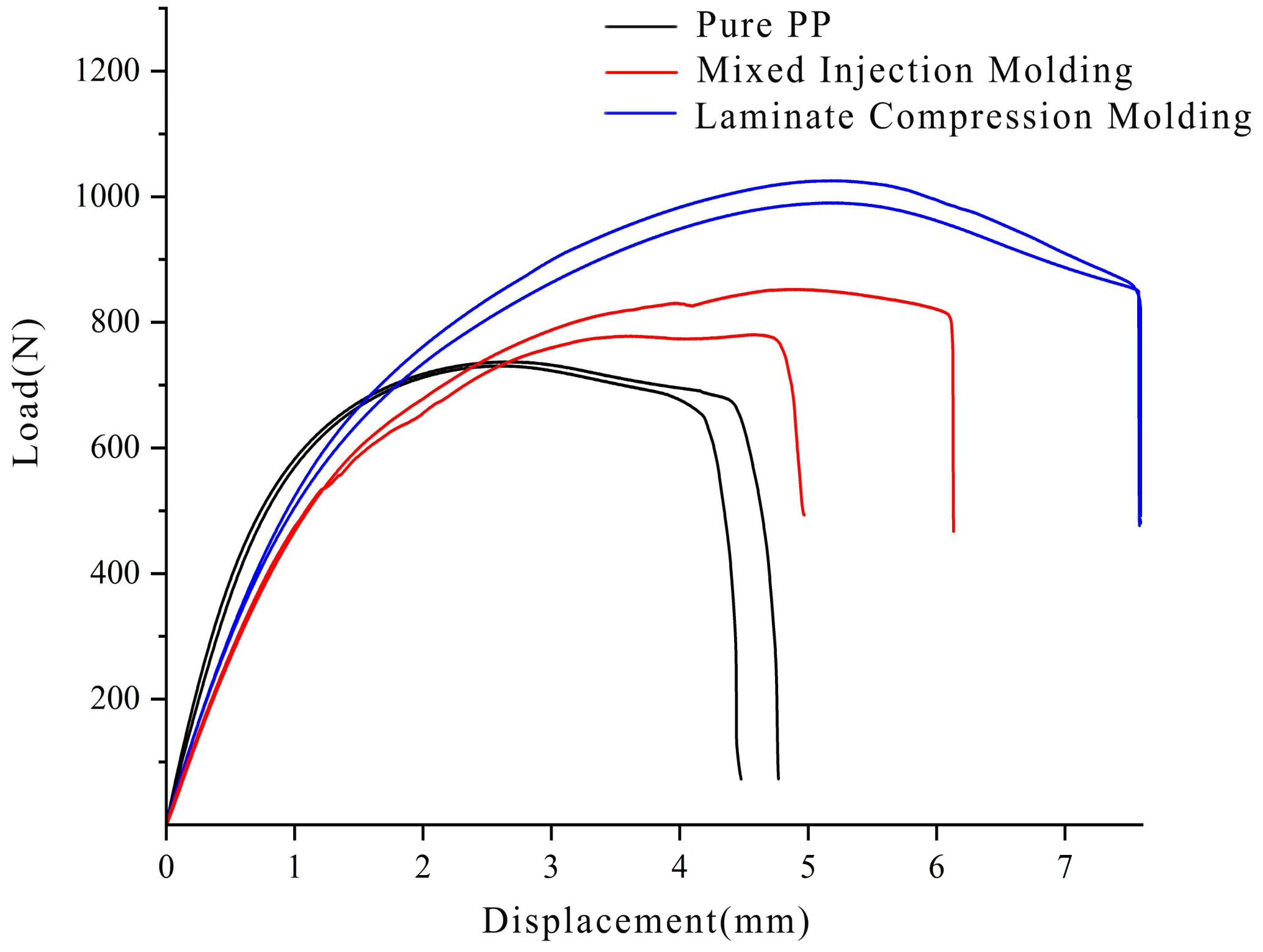
Based on our data analysis of the tensile strength and modulus of the two different composite materials with varying coconut shell-fiber contents, we determined that the composite material with 5% coconut shell-fiber content exhibited an optimal performance. To provide a more intuitive analysis of the tensile performance of the composite material with 5% coconut shell-fiber content, we produced tensile curves of the two types of composite materials with 5% coconut shell-fiber content and the pure PP-material specimens, as shown in Figure 3.
To provide a clear and comprehensive display of the tensile process of each material specimen, two specimens from each of the three types of materials were selected and plotted. This process facilitated a more intuitive comparison and analysis. Different specimens from the same material showed consistent trends in their load–displacement curves, indicating reproducibility within the same batch of material specimens. The differences between specimens of the stacked compression-molded composite material and pure PP material were relatively small, whereas the differences between specimens of the injection-molded composite material were relatively large. We can mainly attribute this to the difficulty we encountered in achieving homogeneous mixing during the process of blending the short coconut shell-fiber reinforcement with the injection-molded composite material. Consequently, it is possible for local fiber clustering and uneven distribution of fibers to occur, leading to variations in the material properties of different specimens.
Of the three materials, the performance of the stacked compression-molded composite material is superior. The maximum load borne by the standard specimen can reach around 1000 N, with a deformation of approximately 7.5 at the point of fracture. In comparison, although the performance of the injection-molded composite material also represents an improvement upon pure PP material, it is still inferior to the stacked compression-molded composite material.
In conclusion, among the seven different materials tested, the stacked compression-molded composite material with a 5% coconut fiber content exhibited the best overall tensile performance.

3.1.2. Analysis of the Bending Performance of Composite Materials

Based on the bending-test results mentioned above, including pure PP material, coconut-fiber mixed injection-molded composite materials (with 5%, 10%, and 15% content), and coconut-fiber laminated compression-molded composite materials (with 5%, 10%, and 15% content), a total of seven groups of tested materials were used to plot bending strength and bending modulus, as shown in Figure 4 and Figure 5.
  • Bending strength
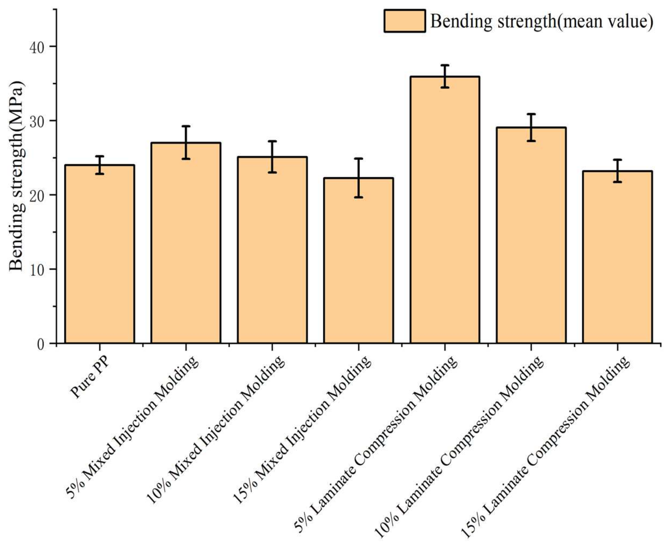
Figure 4 illustrates the bending strength of composite materials with different coconut fiber contents that were subjected to injection molding and laminate compression molding. The x-axis represents the coconut fiber content in the composite material, while the y-axis represents the bending strength of the material.
Both injection-molded and laminate compression-molded composite materials exhibited their maximum bending strength when a coconut fiber content of 5% was present. The maximum bending strength of laminate compression-molded composite materials was 35.94 MPa, representing a 49.8% increase compared to that of pure PP material of the same brand and batch. On the other hand, the maximum bending strength of injection-molded composite materials was 27.03 MPa, showing a 12.6% increase compared to that of pure PP material of the same brand and batch.
When the coconut fiber content exceeded 5%, both injection-molded and laminate compression-molded composite materials experienced a gradual decrease in bending strength. For laminate compression-molded composite materials, the bending strength decreased by 19.1% and 35.4%, respectively, in materials with 10% and 15% coconut fiber contents, relative to the maximum value. The overall rate of decrease was consistent, but the magnitude of decrease was significant. When the coconut fiber content was 15%, the bending strength reached a minimum of 23.22 MPa, which is slightly lower than that of the pure PP material. Additionally, in injection-molded composite materials with 10% and 15% coconut fiber contents, the bending strength decreased by 7.1% and 17.6%, respectively, relative to the maximum value. Bending strength decreased in a similar manner to the laminate compression-molded composite materials, but the overall decreasing trend was relatively gentle. The material with a coconut fiber content of 15% had a minimum bending strength of 22.26 MPa, which is slightly lower than that of the pure PP material and laminate compression-molded composite materials with the same coconut fiber content.
The significant increase in the bending strength of laminate compression-molded composite materials compared to pure PP material can mainly be attributed to the composite process, within which the coconut fiber reinforcement and PP matrix are compressed under a high temperature and pressure. Additionally, coconut fibers undergo alkali treatment and coupling agent treatment, which removes impurities such as pectin from the surface. The bonding mechanism involves the hydrolysis of alkoxy groups in the silane coupling agent to form trihydroxy silane, in which the hydroxyl groups react with the -OH groups in coconut fibers to form a stable structure [33]. Moreover, the organic functional groups (-NH2) on the coupling agent react with PP to form a covalently bonded cross-linked structure, significantly enhancing the interfacial bonding between the fiber and PP material. This enhancement leads to improved bending strength in laminate compression-molded composite materials. This principle may be demonstrated as follows:
The ethoxy (-OEt) groups in KH550 hydrolyze to generate silanol (Si-OH) in the presence of water:
(CH3CH2O)3Si(CH2)3NH2 + 3H2O → (HO)3Si(CH2)3NH2 + 3CH3CH2OH
After hydrolysis, the silanol groups can further condense to form a siloxane network, which reacts with the hydroxyl (-OH) groups on the fiber surface to form a strong chemical bond:
(HO)3Si(CH2)3NH2 + Fiber-OH → Fiber-O-Si(CH2)3NH2 + 3H2O
The amino (-NH2) groups of KH550 can react with some active groups (such as carbonyl or carboxyl groups) on the surface of the polypropylene matrix to further enhance the bonding between the fiber and the matrix:
PP-COOH + NH2-(CH2)3Si-O-Fiber → PP-CONH-(CH2)3Si-O-Fiber + H2O
2.
Bending modulus
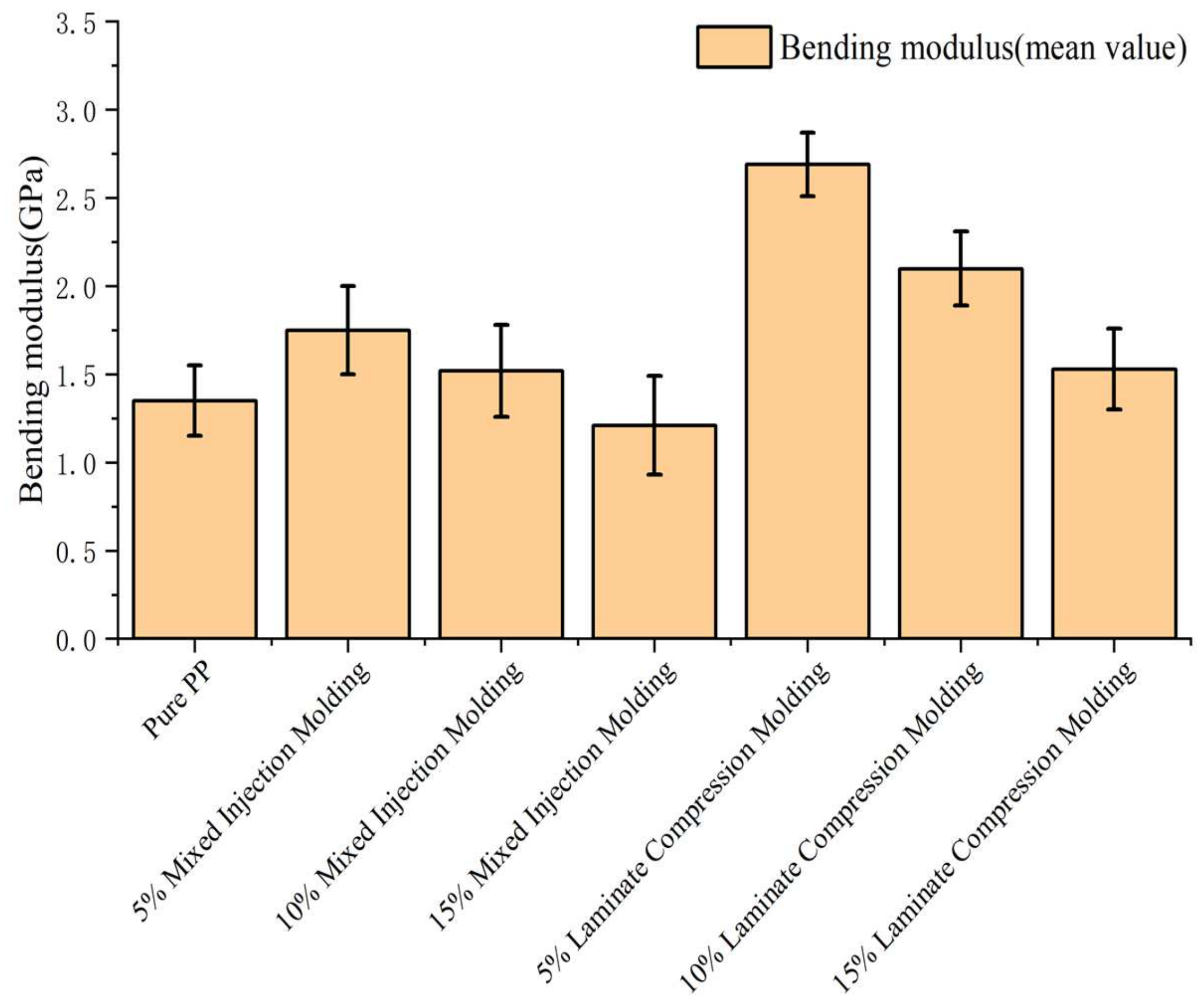
The graph shown in Figure 5 represents the bending modulus of composite materials with different coconut fiber contents subjected to both injection-molding and laminated compression-molding processes. The horizontal axis represents the coconut fiber content in the composite material, while the vertical axis represents the bending modulus of the material.
Both the bending modulus of the injection-molded and laminated compression-molded composite materials reached their maximum values when the coconut fiber content was 5%. The maximum bending modulus of the laminated compression-molded composite material was 2.69 GPa, nearly double that of the pure PP material of the same brand and batch. For the injection-molded composite material, the maximum bending modulus was 1.75 GPa, representing a 29.6% increase compared to that of the pure PP material of the same brand and batch.
When the coconut fiber content exceeded 5%, both the injection-molded and laminated compression-molded composite materials experienced varying degrees of decrease in their bending modulus as the coconut fiber content gradually increased. Specifically, for the laminated compression-molded composite material, the bending modulus in materials with 10% and 15% coconut fiber contents decreased by 21.9% and 43.1%, respectively, relative to the maximum value. The overall rate of decrease in bending modulus was similar, but the magnitude of this decrease was larger. When the coconut fiber content was 15%, the bending modulus reached its lowest point, at 1.53 GPa, which is slightly higher than that of the pure PP material. Additionally, for injection-molded composite materials with 10% and 15% coconut fiber contents, the bending modulus decreased by 13.1% and 30.9%, respectively, compared to the maximum value. The decreasing trend in bending moduli was similar to that of the laminated compression-molded composite material, but the overall rate of decrease was slower. The bending modulus of this material reached its lowest point, 1.21 GPa, when the coconut fiber content was 15%; this is slightly lower than that of the pure PP material and laminated compression-molded composite material with the same coconut fiber content.
After the coconut fiber content exceeded 5%, the decrease in the bending moduli of the composite materials with greater coconut fiber contents could be attributed to the same factors causing a decrease in bending strength. Therefore, further elaboration on this point is unnecessary.
3.
Bending test curves of specimens
Based on the analysis of the data above and considering the bending strength and modulus of elasticity of the two different composite materials with varying coconut fiber contents, it can be concluded that the composite material with 5% coconut fiber content exhibited the best performance. In order to provide a clearer and more intuitive analysis of the bending performance of the composite material with 5% coconut fiber content, Figure 6 shows bending curves of the two composite materials with 5% coconut fiber content alongside the curve of the pure PP material.
The graph presented in Figure 6 depicts the load–displacement curves obtained during bending tests of selected samples of pure PP material, the laminated compression-molded composite material with 5% coconut fiber content, and the mixed injection-molded composite material with 5% coconut fiber content. In order to comprehensively illustrate the bending of each material sample and provide a more intuitive comparative analysis, two samples of each of the three tested materials were selected and plotted on the graph.
In conclusion, among the seven tested material groups, the laminated compression-molded composite material with 5% coconut fiber content exhibited the best overall bending performance.

3.2. Scanning Electron Microscopy (SEM) Cross-Section Characterization Analysis

In order to effectively observe and visually demonstrate formation of a composite by the coconut fiber reinforcement and the PP matrix, we selected tensile specimens of the laminated compression-molded and injection-molded composite materials with the optimal 5% coconut fiber content (which performed best in the tensile and bending tests) for cross-section slicing. As the bending specimens reached a preset deflection during testing but did not fracture, only tensile specimens were selected. We conducted a physical performance-oriented empirical analysis via a scanning electron microscopy (SEM) scanning analysis and by taking photographs for characterization.

3.2.1. SEM Characterization Analysis of the Tensile Fracture Surface of Laminated Compression-Molded Composite Materials with 5% Coconut Fiber Content

Figure 7 shows partial SEM images of the tensile fracture surface of the laminated compression-molded composite material with 5% coconut fiber content. The bright columnar structures in the image represent exposed coconut fibers on the fracture surface of the composite material, while the areas with lower brightness and surface irregularities correspond to the PP material matrix on the fracture surface of the composite material.
The coconut fiber reinforcement bonded tightly to the matrix material, with no signs of intact fibers being pulled out. Additionally, no significant voids could be observed between the fibers and the matrix. However, in the images shown in Figure 7a,c,d, some minor voids are visible between the fibers and the matrix material. This phenomenon may be attributed to the fibers continuing to carry the mechanical load even after the matrix material fractured under tension. As the fibers remained engaged in supporting the load, the applied force may have caused partial separation between the fibers and the matrix near the fracture surface.

3.2.2. SEM Characterization Analysis of the Tensile Fracture Surface of Injection-Molded Composite Materials with 5% Coconut Fiber Content

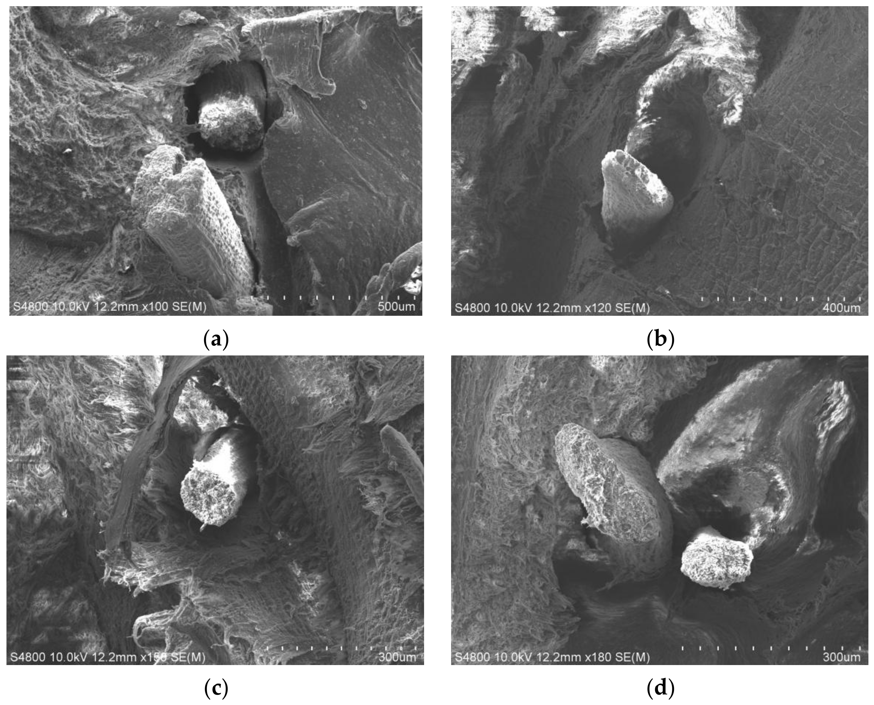
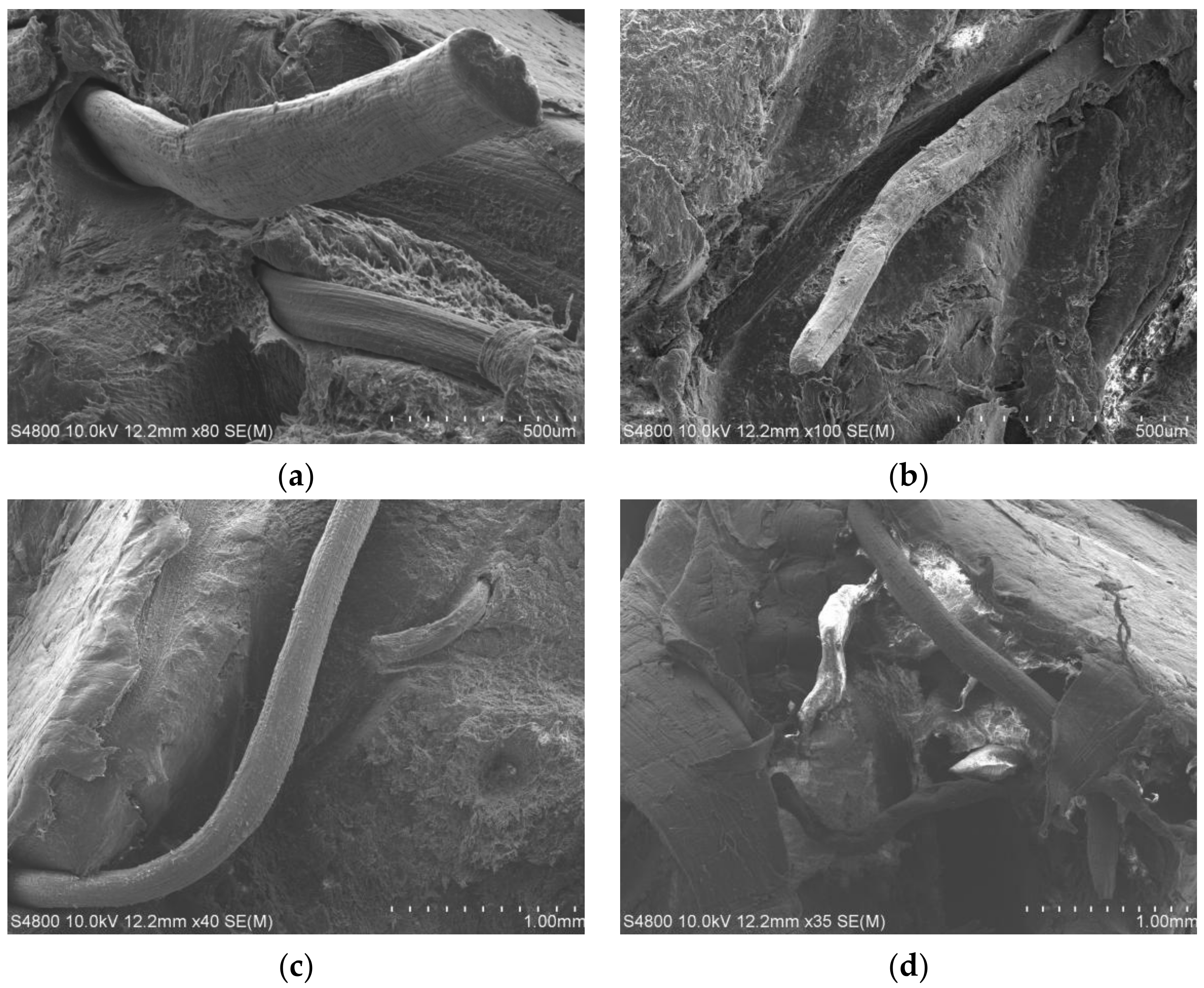
Figure 8 shows partial SEM images of the tensile fracture surface of injection-molded composite materials with 5% coconut fiber content. The cylindrical and filamentous structures visible in the images are the coconut fibers exposed on the fracture surface of the composite material, while the remaining uneven surfaces feature the polypropylene (PP) matrix of the composite material.
Partial coconut fibers inside the injection-molded composite materials did not fracture but were fully pulled when the ultimate load was applied during tension. In Figure 8a, the fracture surface of the coconut fiber appears smooth and regular, indicating that it is not a fracture generated by the tensile stress but, rather, a smooth cut produced during fiber processing.
The coconut fibers were distributed unevenly within the matrix, as shown in Figure 8d. In the same region, the number of fibers varies from 1 to 5, indicating uneven distribution. This uneven distribution of fibers leads to the increased instability of the composite material. The primary reason for this uneven distribution is the light weight and large volume of coconut fibers, thus making it challenging to thoroughly mix them during the blending process. Consequently, this uneven distribution can have a certain impact on the performance of the injection-molded composite material.
The coconut fibers, acting as reinforcement, exhibited a relatively loose bonding with the matrix material, as evidenced by the frequent occurrence of fibers being pulled out intact, as seen in Figure 7a,c. Additionally, clear signs of separation between the fibers and the matrix can be observed in Figure 8b. The primary reason for this phenomenon is that the weaker bonding force between the short coconut fibers and the matrix makes them more prone to being pulled out intact, thereby affecting the overall performance of the injection-molded composite material. In the SEM characterization analysis, this manifested as the fibers being pulled out intact and a separation between the fibers and the matrix. Conversely, in the compression-molded composite material, the long fibers had a larger total contact area with the matrix. Taking into account the same binding force per unit contact area (due to frictional force and chemical bonding, among other factors), the total binding force was greater, resulting in a better performance.
The 3–5 mm short fibers in the injection-molded composite material have various advantages over the long fibers in the compression-molded composite material. The advantage of short fibers, serving as reinforcement in the injection-molded composite material, lies in their homogeneity, which results in isotropic properties [34]. On the other hand, although the compression-molded composite material is heterogeneous and exhibits anisotropic behavior, its performance is superior within a single plane, making it more suitable for sheet-like components (e.g., test specimens). Therefore, this compression-molded composite material is more suitable for the production of panel components of airbag covers.

4. Finite-Element Analysis

In the current international automotive market, the cover panel of an airbag is typically integrated with its base, as shown in Figure 9. In actual use, the cover panel is secured to the car dashboard through slots on the base, ensuring that the airbag can be quickly deployed through the weakened slots on the cover panel. To verify the feasibility of using cross-laminated compression-molded coconut fiber/PP composite materials for the cover panels of airbags for automotive safety, this study utilized Creo for model creation and the finite-element software ANSYS for simulation and validation.

4.1. Airbag Cover Panel Modeling

The types of weakening grooves commonly found in airbag cover panels in currently available domestic and international car models include the H-type, U-type, and double Y-type. Among them, the H-type is easy to process and has shown stable performance, making it the most universal. Therefore, we selected an H-type weakening groove airbag cover panel from a Haima automobile, and its actual dimensional data are shown in Table 1.
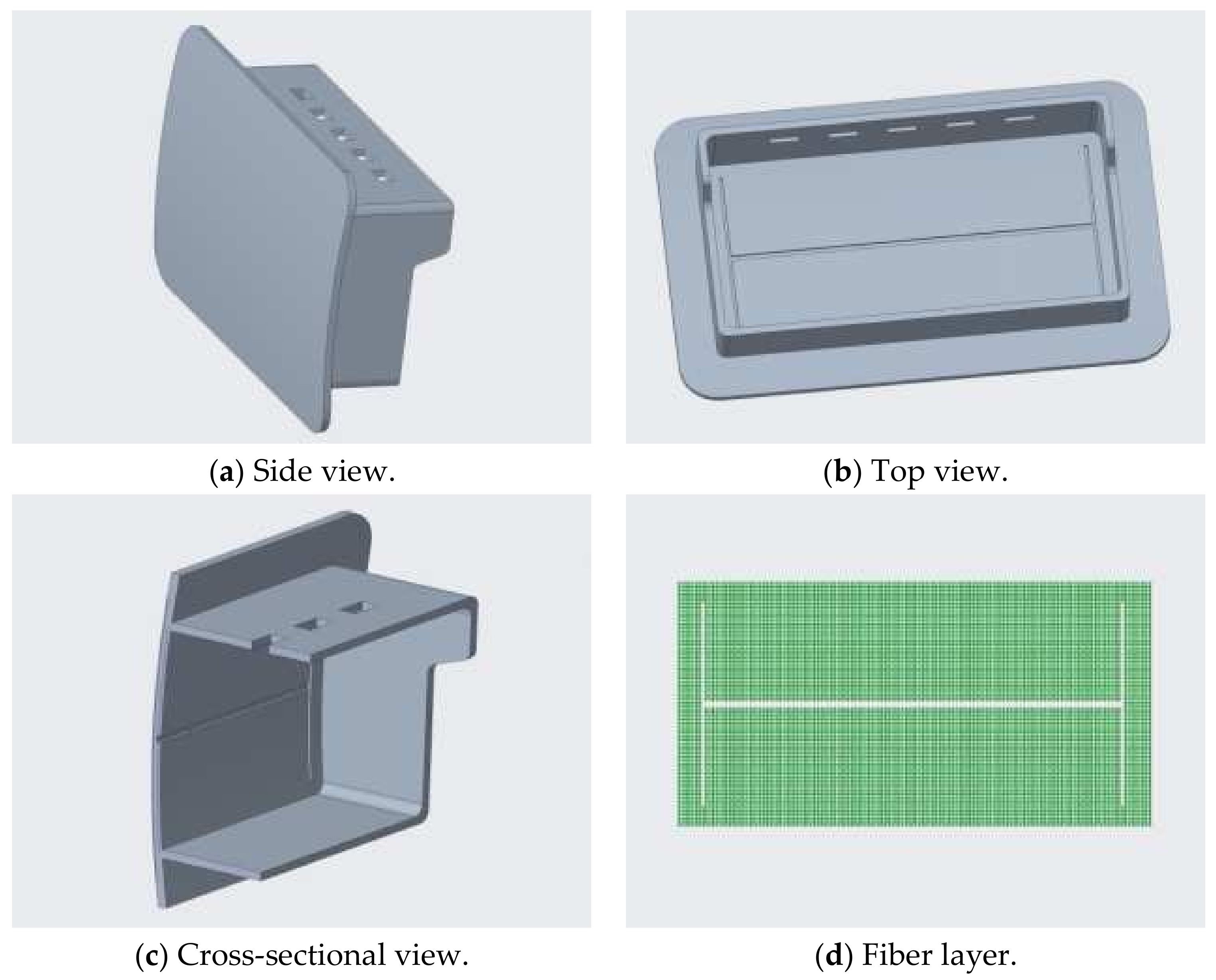
Based on the dimensions of the H-type weakened groove airbag cover panel, a three-dimensional model was established, as shown in Figure 10, in which two layers of meshed coconut fiber were uniformly embedded in the cover panel. One layer was interrupted due to the H-type weakened groove, while the other layer remained intact.
As shown in Figure 10, the model consists of two layers: one of coconut fiber mesh and the other the main body of the cover panel. The diameter of the mesh fibers ranges from 0.3 to 0.5 mm, and the fibers are stacked and distributed to form the mesh structure. The mesh is evenly distributed within the cover panel, making full contact with the matrix material.

4.2. Simplified Airbag Cover Model

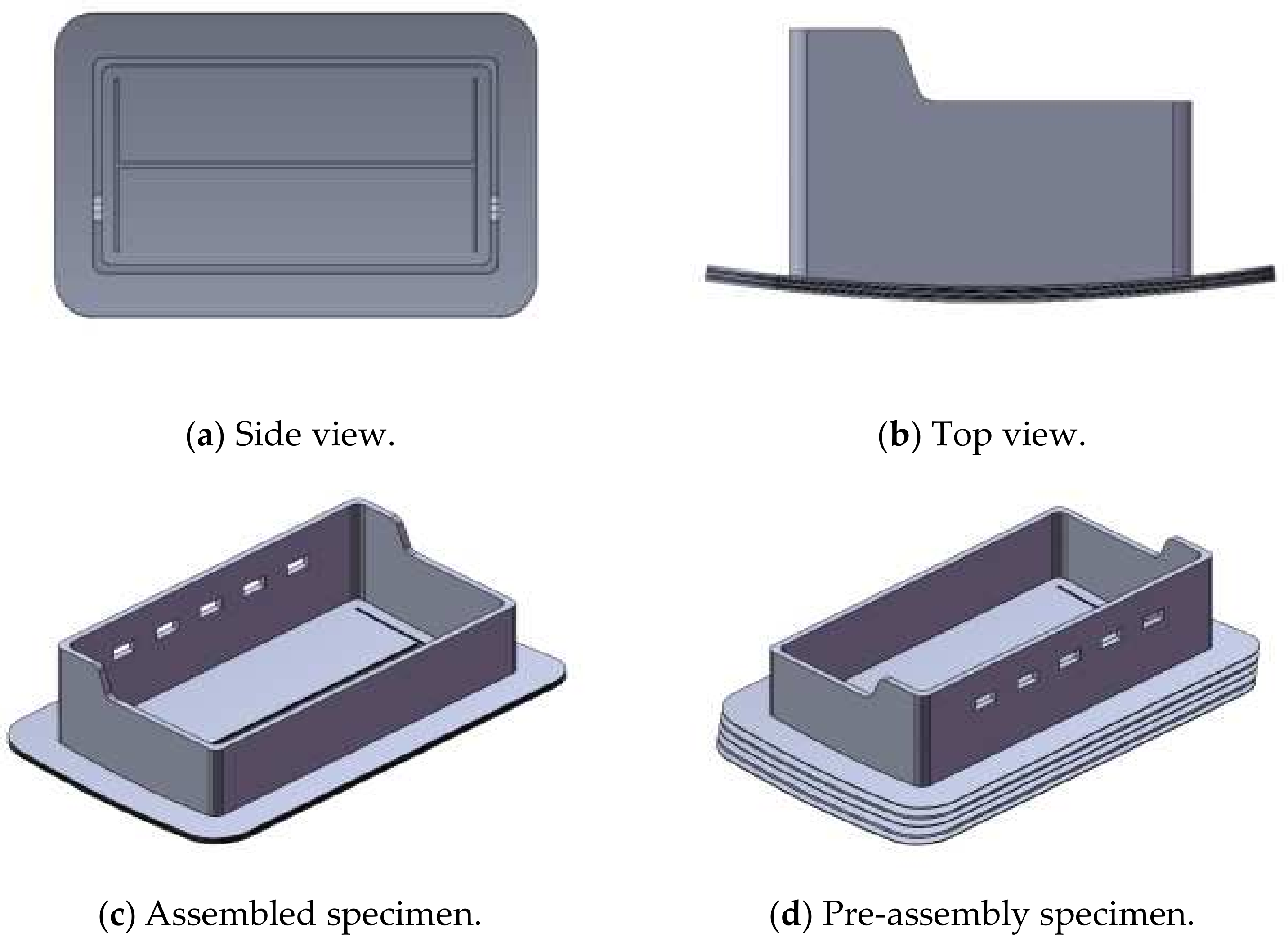
The airbag cover panel is made of laminated compression-molded composite material, and its specific structure is shown in Figure 10. However, due to factors such as the thickness, mechanical strength, and pre-forming condition of the fibrous network, it cannot be quantified as precisely as conventionally cast parts. Moreover, there are numerous contacts between the fibrous network and the matrix, meaning there are high demands in terms of computational resources for finite-element analysis. Therefore, in order to simplify the model of the cover panel’s fibrous network layer, the mesh layer model was simplified to a single thin plate [35]. The mechanical properties and stacking direction of the fibers in the mesh were defined using Hypermesh and ANSYS simulation analysis to obtain the final results. The resulting simplified model of the cover panel assembly is shown in Figure 11.

4.3. The Selection of Material Models and Element Types

In this study, we utilized cross-laminated hot-pressed coconut fiber/PP composite materials, which generally exhibit anisotropic behavior. However, for the purpose of finite element modeling in ANSYS, the composite was simplified by defining each material as a separate component, assuming isotropic properties for each component [36]. This common simplification in finite-element modeling makes computational analysis more manageable, while still providing useful insights. Defining different materials as separate components, we may acknowledge the distinct mechanical properties of the coconut fiber and PP matrix, which influence the overall behavior of the composite. Consequently, data for the 5% coconut fiber material from Table 2 and data for the pure PP material were individually imported into ANSYS for analysis, allowing for an accurate reflection of the properties of each component and leading to more reliable simulation results.
In this study, to select the element type, we utilized the SOLID186 element to define and simulate the performance of the airbag cover panel. SOLID186 is a high-order 3D 20-node solid element, which is defined by 20 nodes, each with three translational degrees of freedom in the x, y, and z directions. SOLID186 exhibits arbitrary spatial anisotropy and supports hyperelasticity, plasticity, stress stiffening, creep, large strain, and large deformation [37]. Therefore, the SOLID186 element is well-suited to this study.

4.4. Mesh Partitioning

Solid mesh partitioning is typically carried out in one of two ways: mapped mesh partitioning and free mesh partitioning. Compared to mapped mesh partitioning, free mesh partitioning is more widely applicable, as it imposes fewer restrictions on element shapes and features, thus offering greater flexibility and convenience. However, free mesh partitioning requires more extensive hardware. Considering the relatively simple nature of our research model, we chose free mesh partitioning. The mesh partitioning of the model is shown in Figure 12.

4.5. Setting Up Contact, Constraints, and Applying Loads

When a car airbag is activated, the detonation impact force is approximately 1764 N, resulting in a pressure of about 70 kPa [38]. In actual conditions, the deployment of the airbag is initiated when it receives signals from sensors, which ignite the explosive device, and then fill the airbag inside the cover plate. Subsequently, the pressure gradually increases on the inner wall of the cover plate until it reaches a critical point [39]. At this point, the cover plate ruptures along the weakening groove, releasing the pressure from the airbag. This entire process occurs within a very short span of time; therefore, we can consider the application of the uniform load to the inner wall of the cover plate to be instantaneous. As the cover plate is a single entity and its base is fixed to the car dashboard, fixed constraints can be added to various locations on the airbag base, as shown in Figure 13.

4.6. Resolution and Analysis

Once the model’s contact, loads, and constraints were set up, the model was solved to obtain the deformation plot and stress contour of the cross-laminated compression-molded coconut fiber/PP composite car airbag cover at the moment of ignition, as shown in Figure 14 and Figure 15.
From Figure 14 and Figure 15, it can be observed that, at the moment of airbag deployment, the stress on the airbag cover is primarily concentrated on the H-shaped weakening groove. This is mainly because the weakening groove is positioned at a relatively weak spot and located at the center of the cover. Among the weakening grooves, the stress is predominantly borne by the central long groove, while the stresses on the shorter grooves on both sides are relatively smaller. Therefore, it can be concluded that, upon airbag deployment, the airbag cover starts to fracture from the central long groove, gradually tearing towards the shorter grooves on both sides until the airbag is fully deployed. Thus, it can be concluded that the studied cross-laminated compression-molded coconut fiber/PP composite material is suitable for application in automotive airbag covers.

5. Conclusions

This study compared the physical properties of coconut shell fiber/polypropylene (PP) composites prepared using different processes, showing that layered hot-pressed materials demonstrated the best comprehensive performance when the coconut fiber content was 5%. In particular, these materials showed enhanced tensile and flexural strength and an almost-doubled flexural modulus. Even with a 15% fiber content, while the tensile strength and modulus decreased, layered hot-pressed materials still outperformed mixed injection-molded materials in terms of mechanical properties. Creo modeling and ANSYS simulation confirmed the potential of this composite for use in automotive airbag covers. This material is lightweight, safe, and cost-effective, and is a great example of an eco-friendly material to be used in the automotive industry which can, therefore, contribute to sustainable development. Future research will focus on optimizing the parameters of its processing to enhance its market competitiveness and potential applications.

Author Contributions

Conceptualization, J.L. and J.C.; methodology, Y.Z.; software, Y.Z.; validation, Y.Z., H.H. and M.S.; formal analysis, J.L.; investigation, M.S.; resources, Y.Z.; data curation, Y.Z.; writing—original draft preparation, Y.Z.; writing—review and editing, Y.Z.; visualization, H.H.; supervision, J.L.; project administration, J.L.; All authors have read and agreed to the published version of the manuscript.

Funding

This research was funded by the National Natural Science Foundation of Hainan Province, grant number 521RC497.

Conflicts of Interest

The authors declare no conflict of interest.

References

  1. Zhang, W.; Xu, J. Advanced lightweight materials for Automobiles: A review. Mater. Des. 2022, 221, 110994. [Google Scholar] [CrossRef]
  2. Czerwinski, F. Current trends in automotive lightweighting strategies and materials. Materials 2021, 14, 6631. [Google Scholar] [CrossRef] [PubMed]
  3. Rajak, D.K.; Pagar, D.D.; Menezes, P.L.; Linul, E. Fiber-reinforced polymer composites: Manufacturing, properties, and applications. Polymers 2019, 11, 1667. [Google Scholar] [CrossRef] [PubMed]
  4. Maiti, S.; Islam, R.; Uddin, M.A.; Afroj, S.; Eichhorn, S.J.; Karim, N. Sustainable fiber-reinforced composites: A Review. Adv. Sustain. Syst. 2022, 6, 2200258. [Google Scholar] [CrossRef]
  5. Mohammadi, H.; Ahmad, Z.; Mazlan, S.A.; Johari, M.A.F.; Siebert, G.; Petrů, M.; Koloor, S.S.R. Lightweight glass fiber-reinforced polymer composite for automotive bumper applications: A review. Polymers 2022, 15, 193. [Google Scholar] [CrossRef] [PubMed]
  6. Ferreira, F.V.; Pinheiro, I.F.; de Souza, S.F.; Mei, L.H.I.; Lona, L.M.F. Polymer composites reinforced with natural fibers and nanocellulose in the automotive industry: A short review. J. Compos. Sci. 2019, 3, 51. [Google Scholar] [CrossRef]
  7. Skosana, S.J.; Khoathane, C.; Malwela, T. Driving towards sustainability: A review of natural fiber reinforced polymer composites for eco-friendly automotive light-weighting. J. Thermoplast. Compos. Mater. 2024. online first. [Google Scholar] [CrossRef]
  8. Olhan, S.; Khatkar, V.; Behera, B.K. Textile-based natural fibre-reinforced polymeric composites in automotive lightweighting. J. Mater. Sci. 2021, 56, 18867–18910. [Google Scholar] [CrossRef]
  9. Kumar, S.; Saha, A. Utilization of coconut shell biomass residue to develop sustainable biocomposites and characterize the physical, mechanical, thermal, and water absorption properties. Biomass Convers. Biorefinery 2022, 14, 12815–12831. [Google Scholar] [CrossRef]
  10. Kamarudin, S.H.; Basri, M.S.M.; Rayung, M.; Abu, F.; Ahmad, S.; Norizan, M.N.; Osman, S.; Sarifuddin, N.; Desa, M.S.Z.M.; Abdullah, U.H.; et al. A review on natural fiber reinforced polymer composites (NFRPC) for sustainable industrial applications. Polymers 2022, 14, 3698. [Google Scholar] [CrossRef]
  11. Oladele, I.O.; Adelani, S.O.; Makinde-Isola, B.A.; Omotosho, T.F. Coconut/coir fibers, their composites and applications. In Plant Fibers, Their Composites, and Applications; Woodhead Publishing: Cambridge, UK, 2022; pp. 181–208. [Google Scholar]
  12. Agarwal, J.; Sahoo, S.; Mohanty, S.; Nayak, S.K. Progress of novel techniques for lightweight automobile applications through innovative eco-friendly composite materials: A review. J. Thermoplast. Compos. Mater. 2020, 33, 978–1013. [Google Scholar] [CrossRef]
  13. Karthik, K.; Rajamanikkam, R.K.; Venkatesan, E.P.; Bishwakarma, S.; Krishnaiah, R.; Saleel, C.A.; Soudagar, M.E.M.; Kalam, M.; Ali, M.M.; Bashir, M.N. State of the Art: Natural Fibre-Reinforced Composites in Advanced Development and their Physical/Chemical/Mechanical Properties. Chin. J. Anal. Chem. 2024, 52, 100415. [Google Scholar] [CrossRef]
  14. Dev, B.; Rahman, A.; Alam, R.; Repon, R.; Nawab, Y. Mapping the progress in natural fiber reinforced composites: Preparation, mechanical properties, and applications. Polym. Compos. 2023, 44, 3748–3788. [Google Scholar] [CrossRef]
  15. Bhat, A.R.; Kumar, R.; Mural, P.K.S. Natural fiber reinforced polymer composites: A comprehensive review of tribo-mechanical properties. Tribol. Int. 2023, 189, 108978. [Google Scholar] [CrossRef]
  16. Dua, S.; Khatri, H.; Naveen, J.; Jawaid, M.; Jayakrishna, K.; Norrrahim, M.; Rashedi, A. Potential of natural fiber based polymeric composites for cleaner automotive component production—A comprehensive review. J. Mater. Res. Technol. 2023, 25, 1086–1104. [Google Scholar] [CrossRef]
  17. Söylemez, M.A.; Özer, K.; Ozer, D. Biofibers and Their Composites for Industrial Applications. In Handbook of Bioplastics and Biocomposites Engineering Applications; Wiley-Scrivener Publishing LLC: Beverly, MA, USA, 2023; pp. 513–538. [Google Scholar]
  18. Martinelli, F.R.B.; Ribeiro, F.R.C.; Marvila, M.T.; Monteiro, S.N.; Filho, F.d.C.G.; de Azevedo, A.R.G. A review of the use of coconut fiber in cement composites. Polymers 2023, 15, 1309. [Google Scholar] [CrossRef]
  19. Inegbedion, F.; Inegbedion, F.; Osasona, I.E. Coconut Fibre (Coir) Composites: A Review. J. Mater. Eng. Struct. Comput. 2024, 3, 15–30. [Google Scholar]
  20. Stelte, W.; Reddy, N.; Barsberg, S.; Sanadi, A.R. Coir from Coconut Processing Waste as a Raw Material for Applications Beyond Traditional Uses. BioResources 2023, 18, 49. [Google Scholar] [CrossRef]
  21. Patel, R.V.; Yadav, A.; Winczek, J. Physical, mechanical, and thermal properties of natural fiber-reinforced epoxy composites for construction and automotive applications. Appl. Sci. 2023, 13, 5126. [Google Scholar] [CrossRef]
  22. Mou, Y.; Li, J.; Li, J.; Hong, S.; Ji, C. Feasibility study on the application of coconut shell fiber/PP composite material based on Abaqus in automotive airbag cover plates. Plast. Technol. 2020, 48, 94–97. [Google Scholar]
  23. Mosi, G.; Ikua, B.; Kabini, S.; Mwangi, J. Characterization and Modeling of Mechanical Properties of Additively Manufactured Coconut Fiber-Reinforced Polypropylene Composites. Adv. Mater. Phys. Chem. 2024, 14, 95–112. [Google Scholar] [CrossRef]
  24. Simamora, P.; Simanjuntak, J.; Sinulingga, K.; Laksono, A.D. Mechanical Properties of Polypropylene Composites with Different Reinforced Natural Fibers—A Comparative Study. J. Ecol. Eng. 2023, 24, 311–317. [Google Scholar] [CrossRef] [PubMed]
  25. do Nascimento, E.P.; Luna, C.B.B.; Ferreira, E.D.S.B.; dos Santos Filho, E.A.; Siqueira, D.D.; Wellen, R.M.R.; Araújo, E.M. Extraction of natural fibers of Catole coconut (Syagrus Cearensis, application as reinforcing filler in polypropylene-based composites. Polym. Compos. 2023, 44, 5891–5909. [Google Scholar] [CrossRef]
  26. Yusuf, Y.; Mustafa, N.; Mastura, M.T.; Latip, M.A.M.; Hadi, S.D. Development of 3D Printing Filament Material Using Recycled Polypropylene (rPP) Reinforced with Coconut Fiber. In Additive Manufacturing for Biocomposites and Synthetic Composites; CRC Press: Boca Raton, FL, USA, 2023; pp. 59–75. [Google Scholar]
  27. Maurya, A.K.; Manik, G. Advances towards development of industrially relevant short natural fiber reinforced and hybridized polypropylene composites for various industrial applications: A review. J. Polym. Res. 2023, 30, 47. [Google Scholar] [CrossRef]
  28. James, R.M.S.; Gisip, J.; Mohd Yusof, N. Effect of chemical treatment on physical and mechanical properties of coir fibre-polypropylene composites. Sci. Res. J. 2023, 20, 145–157. [Google Scholar]
  29. Balogun, O.A.; Daramola, O.O.; Adediran, A.A.; Akinwande, A.A.; Bello, O.S. reinforced polypropylene composites for automobile application: Mechanical, wear and flow properties. Alex. Eng. J. 2023, 65, 327–341. [Google Scholar] [CrossRef]
  30. Kaliappan, S.; Natrayan, L. Polypropylene Composite Materials with Natural Fiber Reinforcement: An Acoustic and Mechanical Analysis for Automotive Implementations; SAE Technical Paper No. 2023-01-5130; SAE International: Warrendale, PA, USA, 2024. [Google Scholar]
  31. GB/T 1040.1-2018; Determination of Tensile Properties of Plastics Part 1: General Principles. China National Standardization Administration: Beijing, China, 2008.
  32. ASTM D3039; Standard Test Method for Tensile Properties of Polymer Matrix Composite Materials. ASTM: West Conshohohoken, PA, USA, 1995; pp. 99–109.
  33. Yang, Y.; Zhang, H.; Liu, X.; Deng, Y.; Sun, M.; Wang, J.; Cui, Y.; Pan, L.; Chen, Z. Hierarchical interface design of jute fibers/polypropylene composites for enhanced interfacial and mechanical properties. J. Clean. Prod. 2024, 450, 141966. [Google Scholar] [CrossRef]
  34. Müller, V.; Brylka, B.; Dillenberger, F.; Glöckner, R.; Kolling, S.; Böhlke, T. Homogenization of elastic properties of short-fiber reinforced composites based on measured microstructure data. J. Compos. Mater. 2016, 50, 297–312. [Google Scholar] [CrossRef]
  35. Tenek, L.T.; Argyris, J. Finite Element Analysis for Composite Structures; Springer Science & Business Media: New York, NY, USA, 2013. [Google Scholar]
  36. Mallick, P.K. Fiber-Reinforced Composites: Materials, Manufacturing, and Design; CRC Press: Boca Raton, FL, USA, 2007. [Google Scholar]
  37. Hao, W.; Liu, C.; Shen, H. Application Examples of ANSYS in Civil Engineering; China Water & Power Press: Beijing, China, 2005; pp. 14–23. [Google Scholar]
  38. Maurya, A. Study of Mechanical Properties of Coconut Coir Fiber Reinforced Epoxy Biocomposite. Master’s Thesis, Integral University, Lucknow, India, 2021. [Google Scholar]
  39. Cheng, Y.; Li, Y.; Yang, C. The design of an airbag automatic inflator and the simulation analysis of airbag in the unfolding process. In Proceedings of the 2020 5th International Conference on Mechanical, Control and Computer Engineering (ICMCCE), Harbin, China, 25–27 December 2020; IEEE: Toulouse, France, 2020; pp. 961–965. [Google Scholar]
Figure 1. Tensile strength versus coconut shell-fiber content of injection-molded and layered hot-pressed coconut fiber-reinforced polypropylene composites.
Jcs 08 00328 g001
Figure 2. Tensile modulus versus coconut shell-fiber contents of injection-molded and layered hot-pressed coconut fiber-reinforced polypropylene composites.
Jcs 08 00328 g002
Figure 3. Tensile load–displacement curves of injection-molded and layered hot-pressed 5%wt. coconut fiber-reinforced polypropylene composites, as compared to pure polypropylene.
Jcs 08 00328 g003
Figure 4. Bending strength versus coconut shell-fiber content of injection-molded and layered hot-pressed coconut fiber-reinforced polypropylene composites.
Jcs 08 00328 g004
Figure 5. Bending modulus versus coconut shell-fiber content of injection-molded and layered hot-pressed coconut fiber-reinforced polypropylene composites.
Jcs 08 00328 g005
Figure 6. Schematic diagram of partial spline-bending curve.
Jcs 08 00328 g006
Figure 7. SEM characterization of tensile sections of laminated hot-pressed composites with 5% coconut fiber content, where images (ad) represent different tensile sections.
Jcs 08 00328 g007
Figure 8. SEM characterization of tensile sections of mixed injection-molded composites with 5% coconut fiber content, where images (ad) represent different tensile sections.
Jcs 08 00328 g008
Figure 9. Panel of an airbag cover (backside).
Jcs 08 00328 g009
Figure 10. Model of a laminated hot-pressed composite airbag cover panel.
Jcs 08 00328 g010
Figure 11. Simplified model of a laminated hot-pressed composite airbag cover.
Jcs 08 00328 g011
Figure 12. Grid partitioning.
Jcs 08 00328 g012
Figure 13. Load and constraints of the model.
Jcs 08 00328 g013
Figure 14. Schematic diagram of model deformation.
Jcs 08 00328 g014
Figure 15. Cloud map of modeled stress.
Jcs 08 00328 g015
Table 1. Size of the selected airbag cover panel.
The Length of the Cover PanelThe Width of the Cover PanelThe Length of the Airbag CompartmentThe Width of the Airbag CompartmentThe Height of the Highest Point of the Airbag CompartmentThe Height of the Lowest Point of the Airbag CompartmentThe Thickness of the Airbag Cover Panel
250.02 mm158.46 mm210.02 mm112.08 mm65.39 mm45.93 mm4 mm
Table 2. Experimental data of composite materials.
Tensile Strength/MPaTensile
Modulus/GPa
Bending Strength/MPaBending
Modulus/GPa
Pure PP material18.251.32241.35
5% Stacked Compression Molding25.121.1735.942.69
Disclaimer/Publisher’s Note: The statements, opinions and data contained in all publications are solely those of the individual author(s) and contributor(s) and not of MDPI and/or the editor(s). MDPI and/or the editor(s) disclaim responsibility for any injury to people or property resulting from any ideas, methods, instructions or products referred to in the content.