1. Introduction
The development of energy production on the basis of renewable energy sources (solar, wind, water flow energy plants, etc.) is required for the elaboration of energy accumulators, the usage of which permits one to overcome a time lag between the periods of maximum production and the maximum consumption of energy. The accumulation of the thermal energy can be performed using phase change materials (PCM) in which the energy storage and release occurs as a result of the phase transition (see [
1,
2] and the works cited there). The usage of thermal energy accumulators on the basis of PCMs permits the temperature stabilization of computer complexes [
3], accumulator batteries [
4,
5], solar cells [
6], and other electron devices, as well as the smoothing thermal fluctuations of the environment stabilizing the temperature of living and industrial rooms without additional energy expenses [
7]. In addition, one should mention the usage of PCM in nanophotonics, where phase transition serves as a tool for switching an element of an information system [
8].
The main difficulty arising at the usage of PCMs in the above-listed systems relates to a rather low thermal conductivity coefficient of most PCMs, which account for a fraction of
. At such a low thermal conductivity coefficient, PCMs possess a considerable thermal inertia and respond to the temperature variations of the environment too slow. For this reason, many efforts were undertaken to create phase change materials with an enhanced thermal conductivity coefficient. Two approaches can be applied to overcome this difficulty. In accordance with the first one [
6], a PCM is placed into a cavity of a minimal transverse size, which allows one to shorten the thermal exchange time down to acceptable magnitudes. Another approach [
9] is based on doping PCM with the nanocarbon particles (carbon nanotubes, graphene, graphite nanoparticles, etc.) have the thermal conductivity coefficient exceeding that for PCM by 4–5 orders of magnitude. Doping a PCM with nanocarbon particles provides the percolation heat transport, when the heat propagates along some number of percolation paths formed by the contacting particle having high thermal conductivity. A notable enhancement of the thermal conductivity coefficient (by about an order of magnitude) is reached at a content of nanocarbon particles of several percent. Both approaches result in a considerable shortening of the characteristic time of thermal exchange between PCM and the environment, which provides a possibility for the wide practical usage of PCMs.
There are several types of substances having the properties of phase change materials. First of all one should list paraffin wax-based materials CnH2n+2, fatty acids CH3(CH2)nCOOH, and salt hydrates (MxNy·nH2O). The selection of PCM for operation in thermal accumulating devices should be performed by taking into account the phase transition point in the desired operating temperature range, with a quite high phase change enthalpy, a rather low thermal expansion coefficient at the phase transformation, and a congruent melting. Between the above-listed types of PCMs, paraffin waxes seem to be most appropriate for the usage in thermal accumulating systems because the phase transition temperature point can be stated depending on the molecular mass of the paraffin molecule. In addition, paraffin possesses a relatively low cost and chemical stability within the operation temperature range, where it is characterized by a completely reversible freeze/melt cycle, stands for degradation after a large number of freeze/melt cycles, is not corrosive nor explosive, and has a sufficient availability. That is why paraffin has been selected as a PCM in the presented thermal accumulator facility. The main disadvantage of the usage of paraffin as a PCM in thermal accumulating devices relates to a rather low thermal conductivity coefficient of this material, which accounts for about 0.2 W/m K. Such a low thermal conductivity determines a high inertia of the devices which react for temperature changes too slow.
The problem of the enhancement of the thermal conductivity coefficient of polymer-based composites through doping the material with carbon nanoparticles attracts the attention of many research groups (see refs. [
10,
11,
12,
13,
14,
15,
16,
17,
18,
19,
20,
21] and the works cited there). The most usable dopant increasing both the electric conduction and thermal conduction of a material is graphene. The influence of graphene doping onto the thermal conductivity of polymers has been studied in detail in refs. [
10,
11,
12,
13,
14,
15,
16,
17,
18,
19,
20,
21]. The investigations [
17] have shown a 15-fold increase in the thermal conductivity coefficient of paraffin doped with 1% (weight) of thermally reduced graphene. The degree of the enhancement of the thermal conduction coefficient depends on the orientation of graphene sheets relating to the direction of the temperature gradient. The main factor determining the influence of graphene doping on the thermal conductivity coefficient enhancement is the degree of homogeneity of the dopant over the material volume. The known trend of nanocarbon particles to the formation of aggregates prevents the homogeneous volume distribution of graphene sheets, which presents a great challenge for researchers.
In this work, an arrangement of a water thermal accumulator (WTA) is presented and analyzed. In this facility, the thermal energy is accumulated as a result of the interaction of hot water with crystallized PCM. This interaction results in melting PCM, so that the latent phase transition energy is stored in it. For the extraction of thermal energy, the cool water is flowed through a cavity filled with melted PCM. Paraffin, having a melting temperature about 55 °C, is used as a PCM. This material is relatively not expensive; it possesses high chemical and thermal stability. The time of thermal exchange between the water flow and PCM is shortened by the usage of both the above-listed approaches. The thermal conductivity coefficient of PCM is enhanced as a result of doping paraffin with the thermally reduced graphene oxide.
The production procedure and characteristics of thermal reduced graphene oxide have been described in detail in [
22]. Investigations performed there have shown that graphene oxide can be reduced by keeping the material at a temperature of about 800 °C for 10 min. The high quality of graphene produced is proven by the results of measuring the electric conductivity coefficient, which approaches to the reference value for graphite. Therefore, the thermal reduction in graphene oxide provides a relatively simple and non-expensive way for graphene production.
PCM is placed into a cylindrical envelope of a relatively small diameter, which also shortens the time of the thermal exchange between water and PCM. The thermal exchange between the flowing water and PCM in the frame of the accepted geometry of the thermal accumulator is simulated numerically using code set COMSOL Multiphysics. The calculation takes into account the energy stored as a result of the phase transition and includes both the molecular and convection hear transfer. The longitudinal and radial dependences of the PCM temperature were calculated for the various time moments of the thermal exchange. The calculations indicate that the radial temperature dependence of PCM becomes weaker with the time after beginning the water pumping and disappears practically at about 100 s. In addition, the dependence of the characteristic thermal exchange time between the flowing water and PCM on the thermal conductivity coefficient of PCM was calculated. The results of the calculations indicate that the characteristic thermal exchange time decreases with the enhancement of the thermal coefficient up to , after which remains to be almost constant independently on the thermal conductivity coefficient. This result shows the desired content of the dopant necessary for the enhancement of the thermal conduction coefficient, which is attachable through doping the PCM with carbon nanoparticles.
2. Design of the Thermal Accumulator
We consider and analyze a simplest construction of the PCM-based thermal accumulator where water is used as a thermal energy carrier [
23]. A module structure of the thermal accumulator permits one to enhance the energy content of the system via an increase in the number of similar modules.
Figure 1 presents schematically the arrangement of a module. The module contains two concentric cylindrical tubes of radiuses
R1 and
R2 inserted one into another. The internal tube is manufactured from copper having high a thermal conductivity coefficient to facilitate the thermal exchange between the flowing water and PCM. The external tube is manufactured from a plastic material having a low thermal conductivity coefficient, which prevents the thermal energy loss into the environment. The space between the internal and external cylinders is filled with a PCM, while the water flowing through the inner tube is used as an energy carrier. Thermocouples placed into the bulk of PCM provide the temperature control in the process of the thermal exchange.
The passage of hot water through the tube results in heating the PCM and the phase transition in it, so the material is melted and transforms into the liquid state. The energy
E stored in it is expressed as the product of the PCM mass
M via the specific phase transition enthalpy
H:
The passage of cool water through the WTA filled with the melted PCM results in cooling the PCM and phase transition in it, while the water temperature approaches the phase transition point. Therewith, the energy stored in PCM is extracted from the accumulator and can be used for practical purposes.
As a PCM has been used paraffin Π2, the thermophysical characteristics of which are given in Table 1.The PCM mass is determined using the volume of the space between the internal and external cylinders, which is expressed via the radiuses of
R1 and
R2, as shown below:
Here,
ρ is the density of PCM and
L is the length of the tube. The characteristic heat exchange time τ is estimated via the following relation:
where
is the thermal diffusivity of PCM, λ is the thermal conductivity, and
c is the specific heat capacity of the material.
The pilot setup fabricated in accordance with the scheme in
Figure 1 is characterized by the values of
,
, and
. Following Equation (2), one obtains the mass of PCM, which is contained in one module and
amounts as
. According to Equation (1), it corresponds to the energy content of the module
. This energy can be stored in PCM as a result of cooling
water having the temperature exceeding the phase transition point by 20 °C. If pure paraffin without any dopants is used as a PCM, the characteristic thermal exchange time accounts for about 500 s, according to Equation (3). This time can be shortened considerably as a result of inserting the nanocarbon particles into PCM. As is shown in experiment [
17], inserting 1% (wt) of thermally reduced graphene into paraffin results in a 15-fold enhancement of the thermal conductivity. In this case, the characteristic heat exchange time accounts for
. This time determines the minimum duration of the interaction between the hot water and PCM bulk, and therefore, the maximum velocity
of the water flow. Using
one obtains
where
is the cross-section area of the water tube. At a higher flow velocity, the water has no time to spend its thermal energy for paraffin melting and its temperature changes to only a minor extent.
3. Simulation in the Thermal Regime
The thermal exchange between the flowing hot water and PCM in the thermal accumulator was simulated via the means of the code set COMSOL Multiphysics by taking into account the energy accumulation at the phase transition and convection thermal exchange in the liquid PCM. One should note that an example of such a simulation is mentioned in refs. [
24,
25], where the dynamics of the melting and solidification of a PSM has been elaborated in detail using fixed grid numerical models. In the present work, the non-stationary heat conduction equation has been resolved assuming that the thermal conductivity of the inner copper is infinity while that of the polymer external tube is zero. The grid had a variable step depending on the spatial derivative of the temperature. For the PCM temperature, the maximum step was 2.62 mm while the minimum one amounted to 0.494 mm. For the water temperature, the maximum step was 3.31 mm while the minimum one amounted to 0.494 mm.
The thermal conductivity of PCM doped with the thermally reduced graphene oxide was set to
(solid phase) and
(liquid phase). The initial water temperature is 90 °C while the initial PCM temperature is 20 °C. The results of the simulation are shown in
Figure 2 as the dependences of the temperature on the longitudinal and radial coordinates for the different time points. The radial coordinate is reckoned from the tube axis. As can be seen, the calculation results are in a qualitative agreement with the above-performed estimations. The calculations imply that at the water flow velocity of 10 cm/s, the total time for paraffin melting accounts for about 250 s, which corresponds to the mass of passed water of about 1.7 kg. The calculations indicate that the radial temperature dependence is rather minor during practically all the thermal exchange times. The maximum radial temperature dependences are observed at the initial stages of the thermal exchange process; after about 100 s, this dependence becomes indiscriminable.
The thermal exchange between the cool water flow and melted PCM was modeled in the similar manner. The initial water temperature was set to 297 K, which is lower than the phase transition point by 58 K. The simulation results are shown in
Figure 3 as the dependences of the temperature on the longitudinal and radial coordinates for the different time points. The calculations demonstrate that the thermal energy is transferred from the melted paraffin to the flowing water.
This transfer is practically total for about 150 s after beginning the pumping. The calculations performed imply that in this case, the radial dependences of the temperature become weaker with the increasing time after beginning the water flow. After 100 s, the radial temperature differences became indiscriminable.
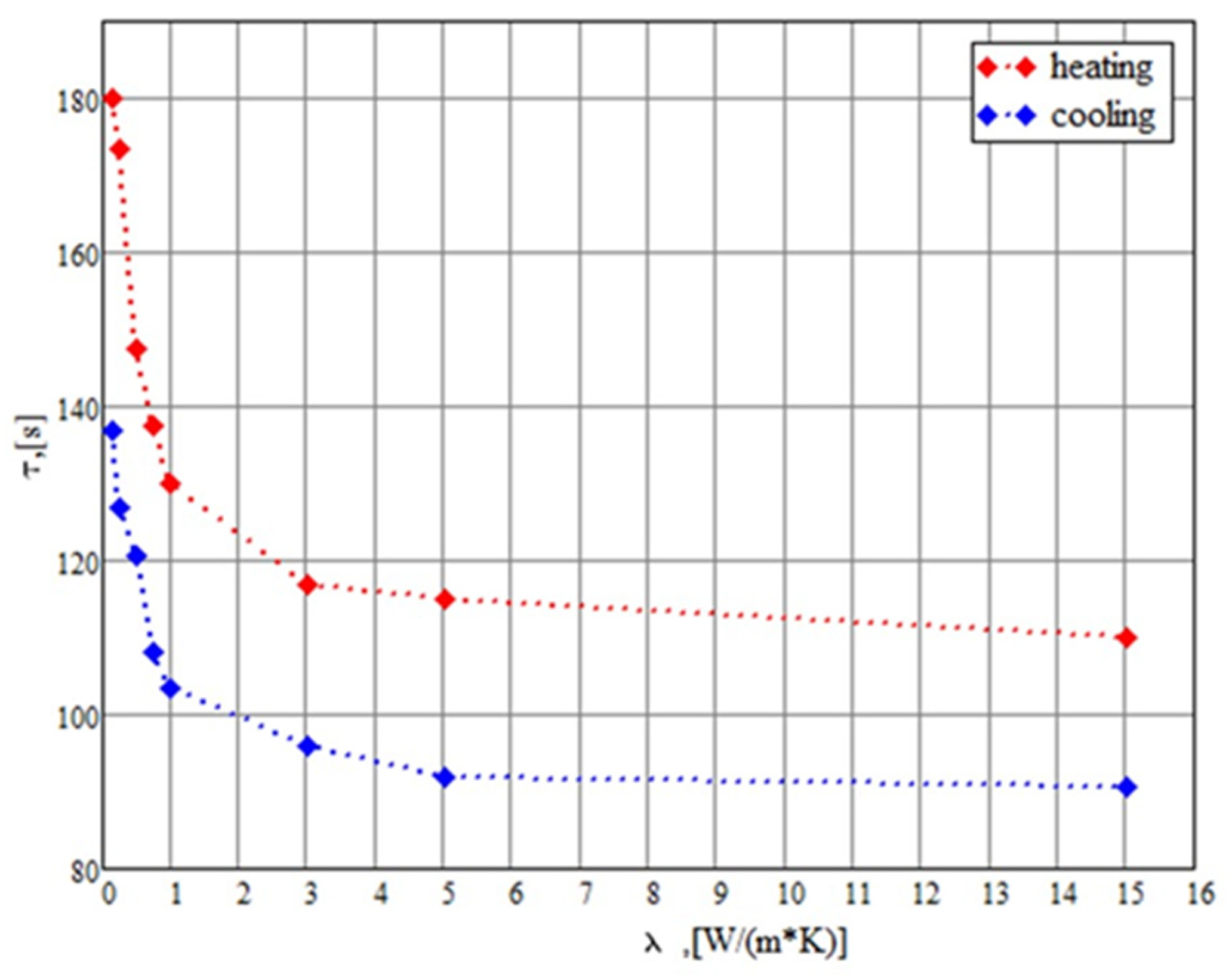
An important parameter determining the thermal exchange between the flowing water and PCM is the characteristic thermal exchange time τ necessary for the transformation of liquid PCM into the solid one and vice versa. This parameter depends on the thermal conductivity coefficient. The characteristic thermal exchange time determines the thermal balance in the device, and specifically, the water flow velocity in accordance with (4). Strictly speaking, the total phase transformation of PCM requires infinite time, but the degree of transformation should be limited by some reasonable value. It is appropriate to define τ as a time required for the phase transformation of 95% material (by mass).
Figure 4 presents the dependence of this parameter on the thermal conductivity coefficient. The calculations were performed basing on the solution of the thermal conduction equation for the thermal accumulator discussed above by taking into account the phase transition energy store. The calculations include both the molecular thermal conduction and the convective thermal exchange in a liquid PCM. As can be seen, the characteristic thermal exchange time decreases sharply as the thermal conductivity coefficient enhances up to about
, after which the dependence becomes rather smooth. The characteristic thermal exchange time corresponding to this value of the thermal conductivity coefficient accounts for approximately 110 c for the heating stage and 90 c for the cooling stage. Such behavior of the characteristic thermal exchange time tending to the saturation can be described via the contribution of the convective thermal conduction into the thermal exchange. At a high thermal conductivity coefficient, the heat transfer is limited by the convection thermal conduction, the contribution of which into the common thermal exchange does not depend on the molecular thermal conductivity coefficient. In these conditions, the characteristic thermal exchange time is determined mainly via the convection mechanism and does not depend
practically on the thermal conductivity coefficient.
Since the calculation results indicate that the characteristic thermal exchange time does not depend on the thermal conductivity coefficient at , it is hardly appropriate to enhance this coefficient above this value. Such an enhancement can be reached at doping the paraffin with reduced graphene oxide at a content of about 2% (weight). Therefore, the above-described module of the thermal accumulator requires doping about 6 g reduced graphene oxide.


 ,
, 


