Abstract
Zirconia is a high-strength ceramic material that expands the design and application possibilities for all-ceramic restorations and dental implants. To enhance the bonding of zirconia restorations to tooth substrates and the osseointegration of implants with the surrounding bone, the surface should be modified by surface treatment. Unfortunately, the effective treatment of sintered zirconia is difficult. Surface treatment for presintered zirconia may be less difficult; thus, the effectiveness of surface treatments of presintered zirconia was investigated herein. The zirconia specimens were randomly divided into eight groups: (1) control (untreated) and seven treated groups subjected to surface treatment (s.ttt.) in the presintered stage, followed by sintering: (2) s.ttt. 1: hydrofluoric acid (HF) gel left during sintering; (3) s.ttt. 2: HF gel washed before sintering; (4) s.ttt. 3: coated with nanosilica; (5) s.ttt. 4: coated with microsilica; (6) s.ttt. 5: coat followed by airborne-particle abrasion; (7) s.ttt. 6: coat followed by partial etching; and (8) s.ttt. 7: coat followed by total etching. The surface microstructure was examined using scanning electron microscopy (SEM) and the crystalline phase was identified using X-ray diffraction (XRD). Biaxial flexural strength was also tested. The results of SEM for s.ttt. 1 and 2 displayed irregular surfaces. S.ttt. 3 showed deeper penetration of the nanosilica into zirconia (27 µm) compared to the microsilica used in s.ttt. 4. S.ttt. 5 and 6 showed irregular coats. S.ttt. 7 showed intergranular pores. The XRD of s.ttt. 1, 2, and 3 revealed tetragonal zirconia as the control group. S.ttt. 4 and 5 showed cristobalite silica and tetragonal zirconia. S.ttt. 6 and 7 contained amorphous silica and tetragonal zirconia, while s.ttt. 7 also showed monoclinic zirconia. The highest flexural strength was for s.ttt. 4 (982.4 MPa), while the lowest was for s.ttt. 7 (386.6 MPa). There was no significant difference in the flexural strength between the control, s.ttt. 1, and 2 (846.3 MPa, 830.0 MPa, and 835 MPa, respectively). Compared to the control group, s.ttt. 3 had a lower flexural strength (634.1 MPa), while s.ttt. 5 and 6 had higher flexural strengths (863.1 MPa and 872.2 MPa, respectively). It can be concluded that the surface modification of presintered zirconia is a promising method as long as no phase transformation or deep subsurface penetration occurs.
1. Introduction
Zirconia (zirconium oxide (ZrO2)) has gained popularity in dentistry over the past few years in a variety of all-ceramic restorations, including inlays, onlays, crowns, and long-span bridges, as well as dental implants [1]. This ceramic material is referred to as “steel” ceramic and this is due to its unique properties of high flexural strength, fracture toughness, fatigue resistance, and radiopacity [2,3]. Therefore, the mechanical properties of zirconia are close to those of metals, but it is white in color. Further, it is possible to exploit different types and thicknesses of zirconia to achieve different shades and degrees of translucency, further enhancing the aesthetics [4]. Zirconia restorations and implants are competitive with metal restorations for esthetic cases in a high-stress loading area, and for implants in cases with thin peri-implant tissues or the risk of gingival recession, when the grey color of titanium implants may show through, leading to unattractive esthetic results [5].
Adhesive dentistry has seen a paradigm shift from being invasive to being minimally invasive due to a revolution in bonding potential [6,7] The bonding of zirconia restorations to tooth substrates is promising if the proper surface treatment of zirconia is achieved. Similarly, the surface characteristics of the restoration, particularly surface roughness, have been shown to be important for bonding [8].
There are three categories of surface roughness, which depend on the size of the features: macro, micro, and nanosized topologies. The macro level has a direct relationship with topographical characteristics that are between a few millimeters and tens of microns in size. Surface roughness is characterized as being in the micro range of between 1 and 10 μm (µm) in the microtopographic profile of dental restorations and implants. Protein adsorption, osteoblastic cell adhesion, and osseointegration rate are all significantly influenced by nanoroughness in the 1–100 nm range. Another strategy for changing the surface is to apply coatings using various techniques, such as plasma spraying, sputter deposition, sol–gel coating, electrophoretic deposition, or biomimetic precipitation [9].
Therefore, the success of restorations and implants is based on the result of a complex interaction between the surrounding substrates and tissues and the zirconia surface. Unfortunately, forming a strong bond with untreated zirconia is difficult due to its great surface stability and chemical inertness [9]. To address this problem, the surface of fully sintered zirconia has been treated using a variety of surface roughening and coating techniques, including both additive techniques such as plasma spray or coatings, and subtractive techniques, such as sandblasting, laser etching, and acid etching [8,10].
Airborne-particle abrasion is a practical method to create surfaces with microroughness. However, there is a strong risk of reduction in mechanical properties after airborne-particle abrasion, in addition to inevitable alumina contamination. It should be noted that the effectiveness of airborne-particle abrasion varies depending on the particle material and size, and on how aggressive the abrasion is [11]. Large particle size and high pressure have been found to be associated with a phase change in zirconia from tetragonal to monoclinic, causing weakened physical properties [12].
Acid etching at room temperature and electrochemical treatments are less effective on zirconia than they are on metals [13]. Coatings have also been developed which may improve the bioactivity, biocompatibility, or possible antibacterial properties of zirconia. However, the stability of these coatings is questionable, with the possibility of debonding from the zirconia restorations and implant. Unfortunately, the surface treatment of sintered zirconia is challenging due to the hard, inert, dense structure of zirconia after the sintering process [13].
Fully sintered zirconia is difficult to cut or modify and causes extremely severe wear on cutting tools. This is the main reason why most manufacturers and systems prefer handling zirconia in the green stage when it is weaker, softer, and more porous. After sintering, zirconia’s high fracture toughness is one of its most appealing qualities as it makes the substance less prone to crack propagation during function [14]. This is due to a crystalline phase transformation [14].
Zirconia is a polymorphic material, which means that it exhibits multiple crystal structures at various temperatures without changing its chemical composition [15]. Zirconia has three different crystal structures: monoclinic (M), tetragonal (T), and cubic (C). Of these, the tetragonal phase is strongest, and the one required in restorations [15].
To stabilize the tetragonal phase of zirconia at room temperature, oxides such as yttrium oxide (Y2O3) can be added. Yttrium-stabilized zirconia is of importance to dentistry, and it contains roughly 2 to 3 mol% yttrium oxide (Y2O3) as a stabilizing factor [16]. Zirconia’s unique mechanical properties mainly depend on the fact that the transformation from the tetragonal to the monoclinic phase is accompanied by volume expansion, which hinders crack propagation and increases the mechanical properties [15].
Although it may be less difficult to treat the surface of presintered zirconia due to its porous, softer structure, it is not frequently studied [16]. In this study, experiments were carried out to modify the surface of zirconia by treating presintered zirconia rather than sintered zirconia. In this investigation, various presintered zirconia surface treatments were investigated. The methods used for surface treatment were subtractive, additive, or a mixture. Seven surface modifications were performed on the presintered zirconia, and after sintering, the surface microstructure, crystalline phase, and flexural strength were assessed and compared to the untreated control zirconia. The null hypothesis postulated that there would be no difference between the control and treated zirconia after sintering as regards surface microstructure, crystalline phase, and biaxial flexural strength.
2. Materials and Methods
The commercial materials used in this study are described in Table 1.

Table 1.
Materials used and their composition, according to the manufacturers.
2.1. Presintered Zirconia Specimen Preparation
A total of 80 disc-shaped presintered zirconia specimens (19 mm diameter × 1.5 mm thickness) were prepared from yttrium-stabilized zirconia blocks. The cutting tip of a milling machine (BV 20B-L, Shandong, China) was used to remove the zirconia blocks’ handles. The zirconia blocks were cemented to flat polymeric bases with cyanoacrylate adhesive (Amir Alpha Co., Tokyo, Japan). The milling tip of the same machine was used to convert the zirconia blocks (15.5 × 19 × 20 mm) into zirconia cylinders (19 mm diameter). The zirconia specimens were cut every 1.5 mm interval using a low-speed saw (Isomet, Buehler, Palatine, IL, USA) and a diamond-coated cutting disc (Struers, Copenhagen, Denmark), resulting in specimens of 19 mm diameter × 1.5 mm thickness.
2.2. Specimen Grouping and Presintered Zirconia Surface Treatment
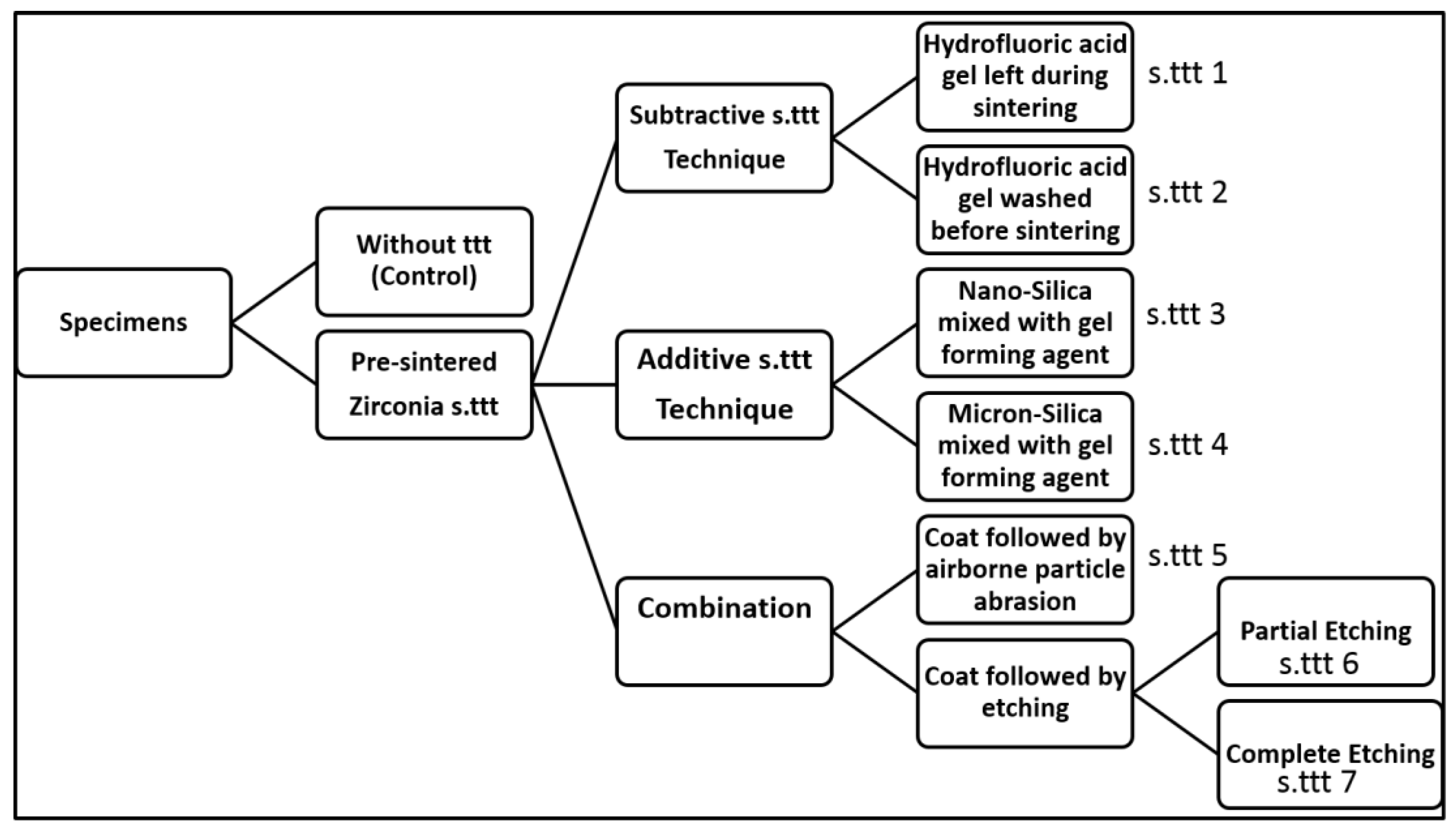
The zirconia specimens were randomly divided into 8 groups: 1 control and 7 treated groups in which the surface of presintered zirconia was treated, followed by the sintering process. The surface treatments were either roughening (subtractive), coating (additive), or both (coat followed by roughening). The study design is shown in Figure 1 with different surface treatments (s.ttt).

Figure 1.
Study design with different surface treatments (s.ttt).
The different presintered surface treatment (s.ttt.) techniques:
2.2.1. Subtractive Surface Treatment Technique
This technique was based on roughening the zirconia surface by applying hydrofluoric acid gel (9%) on the presintered zirconia surface. The acid was either left in place during sintering or washed away.
Hydrofluoric Acid Gel Left on Presintered Zirconia Surface (s.ttt. 1)
Hydrofluoric acid (HF) gel (Ultradent, South Jordan, UT, USA) was applied to the surface of the presintered zirconia and was left when the latter was sintered.
Hydrofluoric Acid Gel Washed from Presintered Zirconia Surface (s.ttt. 2)
The HF gel was applied to the surface of the presintered zirconia for 5 min. Then, the acid was removed before sintering by washing under tap water for 5 min, then ultrasonically cleaning for 5 min in distilled water.
2.2.2. Additive Surface Treatment Technique (Silica Coating)
Due to the high porosity of the presintered zirconia, a gel-forming agent, carboxymethylcellulose (CMC) (Oxford Laboratory Reagent, Navghar, India), was used to coat the zirconia with silica. Without CMC, absorption of the liquid into the pores of the presintered zirconia occurred, with a subsequent detachment of the silica particles. However, using CMC, a thin gel consistency was obtained and applied with a brush (Firster No.12, China) on the surface of the presintered zirconia specimens, which were then sintered.
Denfex nanosilica (Bee Chems, Kanpur, India) was used in this technique, where the nanosilica was dispersed in liquid. The pH of Denfex nanosilica liquid was measured with a pH meter (Accumet, Fisher Scientific, Hampton, NH, USA) and was found to be 9.3. Due to the alcoholic nature of the liquid, it evaporated rapidly, within 3 min, limiting the working time. To overcome this, two approaches were attempted:
Nanosilica Mixed with Gel-Forming Agent (s.ttt. 3)
The nanosilica liquid was diluted with distilled water and then mixed with CMC in the following ratio, giving a thin gel consistency:
0.4 mL of distilled water: 1.2 mL of Denfex nanosilica: 0.0175 g of CMC.
Microsilica Mixed with Gel-Forming Agent (s.ttt. 4)
The liquid of the Denfex nanosilica was left to evaporate and the agglomerated solid mass was crushed using an agate mortar and pestle, followed by sieving through a 38 µm pore size mesh. The produced powder was easily handled with an adequate working time. The sieved silica powder was mixed with a gel-forming agent (GFA) which had been previously mixed with distilled water in the following ratio:
0.0175 gm of GFA: 0.4 mL of distilled water: 0.02 g of silica powder.
The GFA powder was hand-mixed with the distilled water using a plastic spatula for three minutes until a homogenous gel was obtained. Afterwards, the silica powder was added to the gel and mixed for an additional three minutes. Mixing of the silica powder with the mixture of GFA and water was performed just before application to the presintered zirconia. A thin gel consistency was obtained and applied by a brush on the surface of the presintered zirconia specimens once and then sintered.
2.2.3. Combination
The presintered zirconia specimens were subjected to a combined surface treatment. First, the surface was coated with neutral porcelain (VITA Zahnfabrik, Bad Säckingen, Germany) in the following ratio: 0.0175 gm of CMC: 0.4 mL of distilled water: 0.03 g of neutral porcelain. A smooth glassy surface was produced after sintering and then roughened using either airborne-particle abrasion or etching.
Coating Followed by Airborne-Particle Abrasion (s.ttt. 5)
After coating, the resultant glassy surface was exposed to airborne-particle abrasion using a sandblaster (Basic Quattro, Renfert, Germany). Airborne-particle abrasion was performed using a 50 µm aluminum oxide powder (Al2O3). The latter was applied for ten seconds at a working distance of ten millimeters perpendicular to the ceramic surface with two-bar pressure.
Coating Followed by Etching
After coating, the glassy surface was etched with the HF gel (9%) (Ultradent, USA). Partial and complete etching of the glassy layer was performed.
Coating followed by partial etching (s.ttt. 6):
The HF gel was applied on the glassy surface of the coated zirconia for 1 min, followed by washing under tap water for 5 min and then ultrasonically cleaning for 5 min in distilled water.
Coating followed by complete etching (s.ttt. 7):
The HF gel was applied for 10 min on the glassy surface of the coated zirconia, followed by washing and cleaning as mentioned previously.
2.3. Specimen Sintering
The specimens were put in a ceramic crucible filled with sintering beads and sintered in a high-temperature sintering furnace according to the manufacturer’s instructions. After sintering, the specimens’ dimensions were 15 mm diameter and 1.2 mm thickness.
2.4. Test Procedures
2.4.1. Surface Microstructure
The surface microstructure of the specimens (presintered and sintered; control and treated) was investigated using a scanning electron microscope (SEM) (Supra-40, Carl-Zeiss NTS-GmbH, Oberkochen, Germany) with accelerating voltage ranging from 20.0 kV to 30.0 kV.
2.4.2. Crystalline Phase Identification
X-ray diffraction (XRD) analyses were conducted to identify the crystalline phases of the presintered and sintered zirconia (control and various treated groups). The crystallographic structures of the specimens were analyzed using an X-ray diffractometer (X’Pert, Philips, Eindhoven, The Netherland). The surfaces of the specimens were scanned with a copper X-unit (Cu Kα) X-ray at 2theta angles from 0 to 80 degrees with a step size of 0.05 and 2-s step interval.
2.4.3. Flexural Strength Test
According to ISO standard 6872 for dental ceramics, a piston-on-three-balls biaxial flexural strength test was conducted [17]. The disc specimens (15 mm diameter × 1.2 mm thickness) used in the biaxial flexural strength test were balanced on three balls and loaded in the center (n = 10 per group).
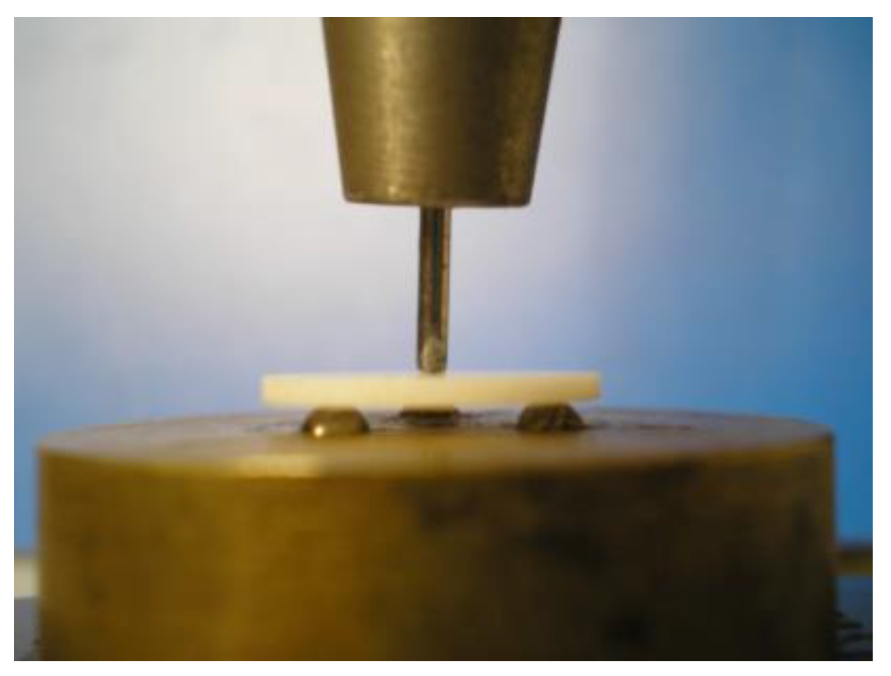
A crosshead speed of 0.15 mm/min was employed in a universal testing machine (Sintec 2/G, MTS system, Eden Prairie, MI, USA) at a speed of 1 mm/min. Three hardened steel balls (3.2 mm diameter) were spaced 120 degrees apart on a 10 mm diameter support circle to support the test specimen. A flat punch (1.4 mm in diameter) applied the load at the center of the disc-shaped specimens, which were arranged concentrically on these supports, as shown in Figure 2.

Figure 2.
Biaxial flexural strength test assembly.
The biaxial flexural strength for each specimen was estimated using the following equation, considering the load at the fracture point [18]:
where S is the flexural strength at fracture (MPa) (maximum center tensile stress),
S = −0.2387 P (X − Y)/d2
P is equal to the total stress that causes the fracture (N),
where ν = Poisson’s ratio; r1 = the radius of the support circle; r2 = the radius of the loaded region; r3 = the radius of the specimen; and d = the specimen thickness at the origin of fracture (mm). Poisson’s ratio of 0.25 is used if the value for the ceramic in question is unknown. In this investigation, ν = 0.25, r1 = 5 mm, r2 = 0.7 mm, and r3 = 7.5 were the values used.
X = (1 + ν) ln (r2/r3)2 + [(1−)/2]. (r2/r3)2, Y = (1 + ν) [1 + ln (r1/r3)2] + (1 − ν) (r1/r3)2
The Shapiro–Wilk test revealed that the data had a normal distribution. One-way ANOVA and the Tukey post hoc test were used to statistically analyze the data in software (IBM-SPSS version 27.0, New York, NY, USA). The significance level was set at p ≤ 0.05. The sample size calculator “G*Power (version 3.1.9.7)” was used to determine the sample size. The estimated sample size was 10 per group.
3. Results
3.1. Surface Microstructure
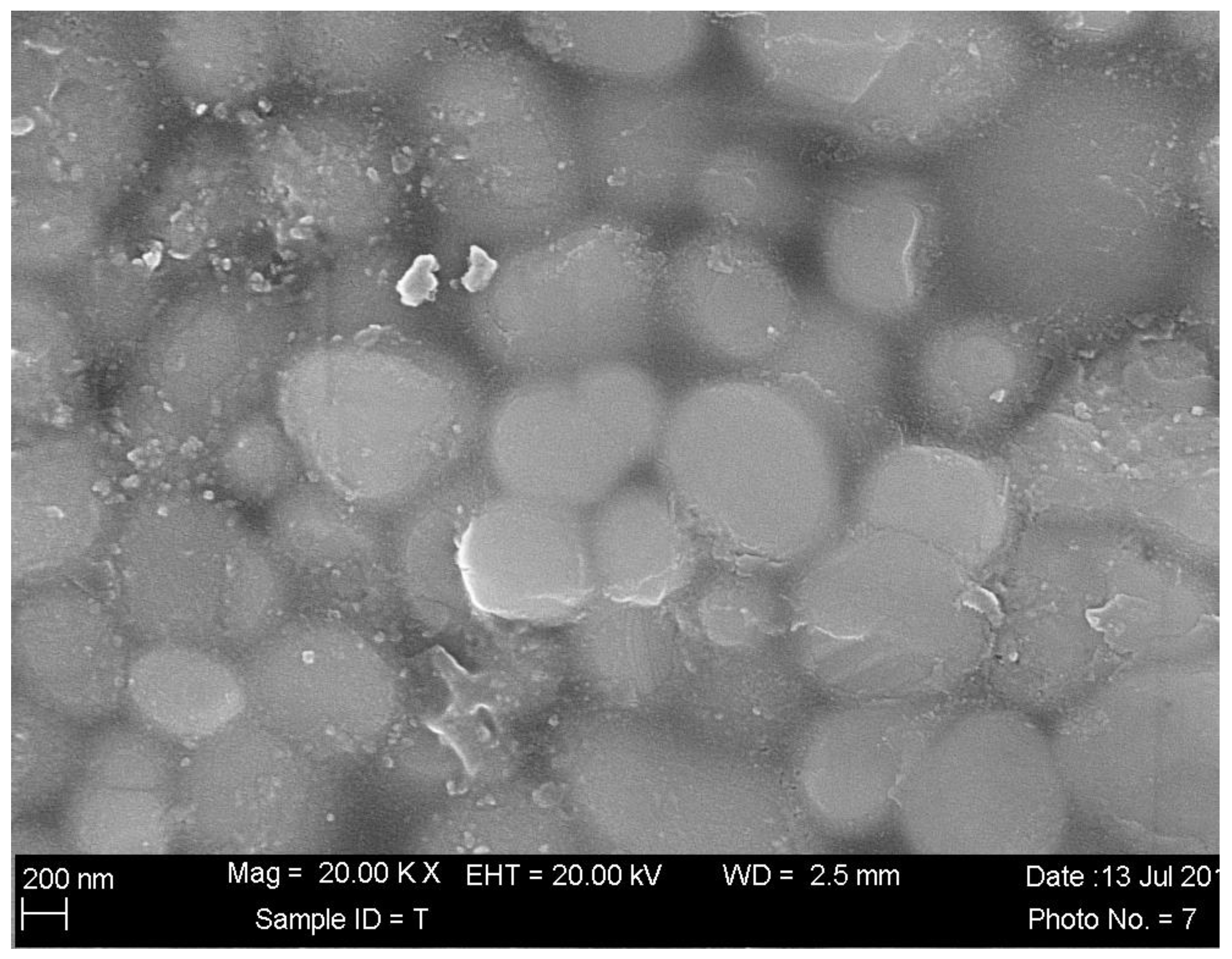
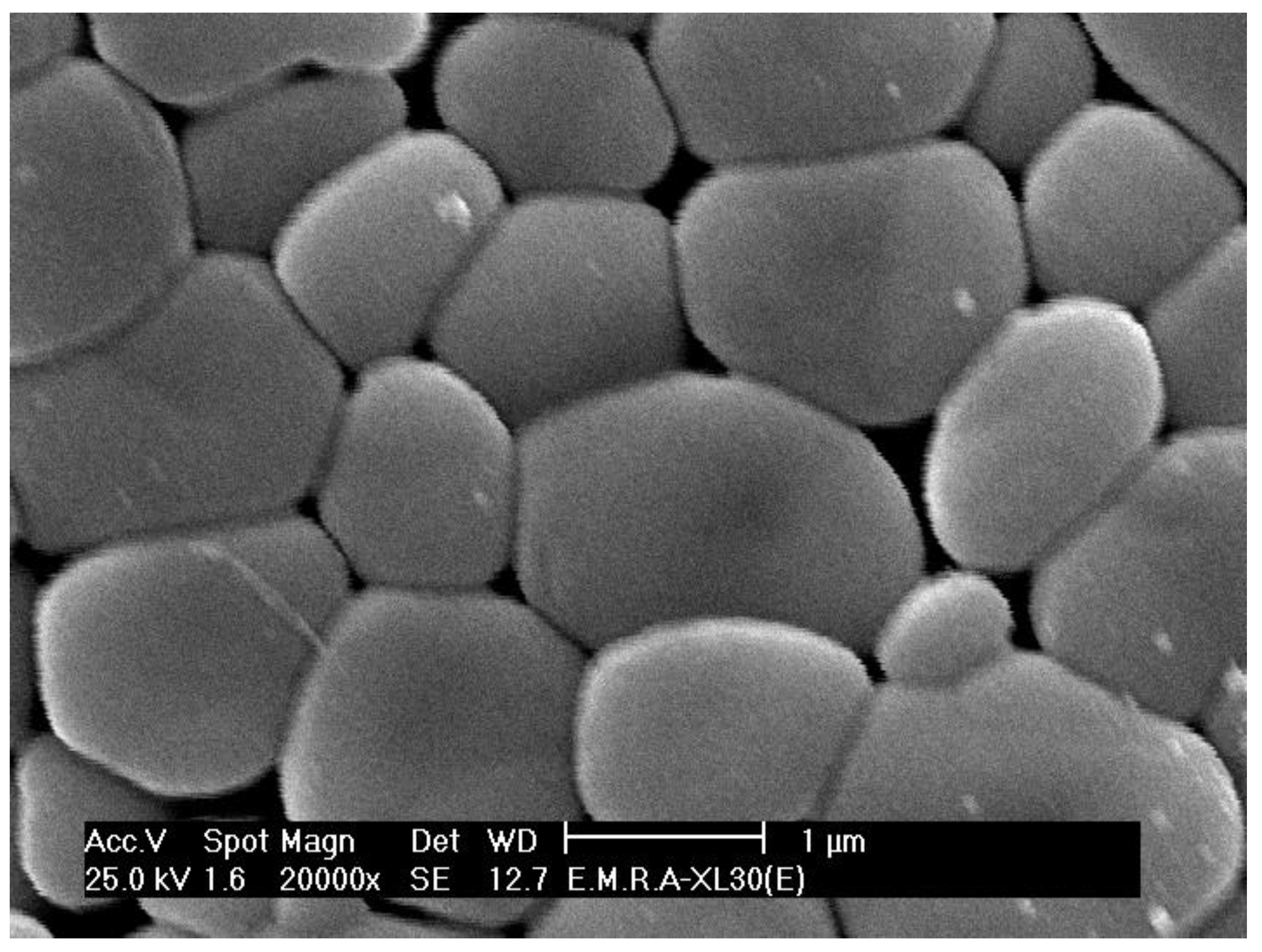
The presintered zirconia specimens showed a porous structure, as shown in Figure 3. On the other hand, after sintering, the control untreated specimens exhibited a dense grain structure, as shown in Figure 4.
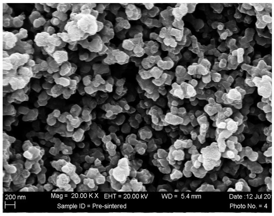
Figure 3.
SEM micrograph of presintered zirconia specimens. Top view, magnification: 20,000×.
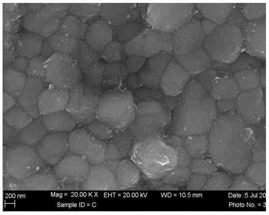
Figure 4.
SEM micrograph of control sintered zirconia specimen. Top view, magnification: 20,000×.
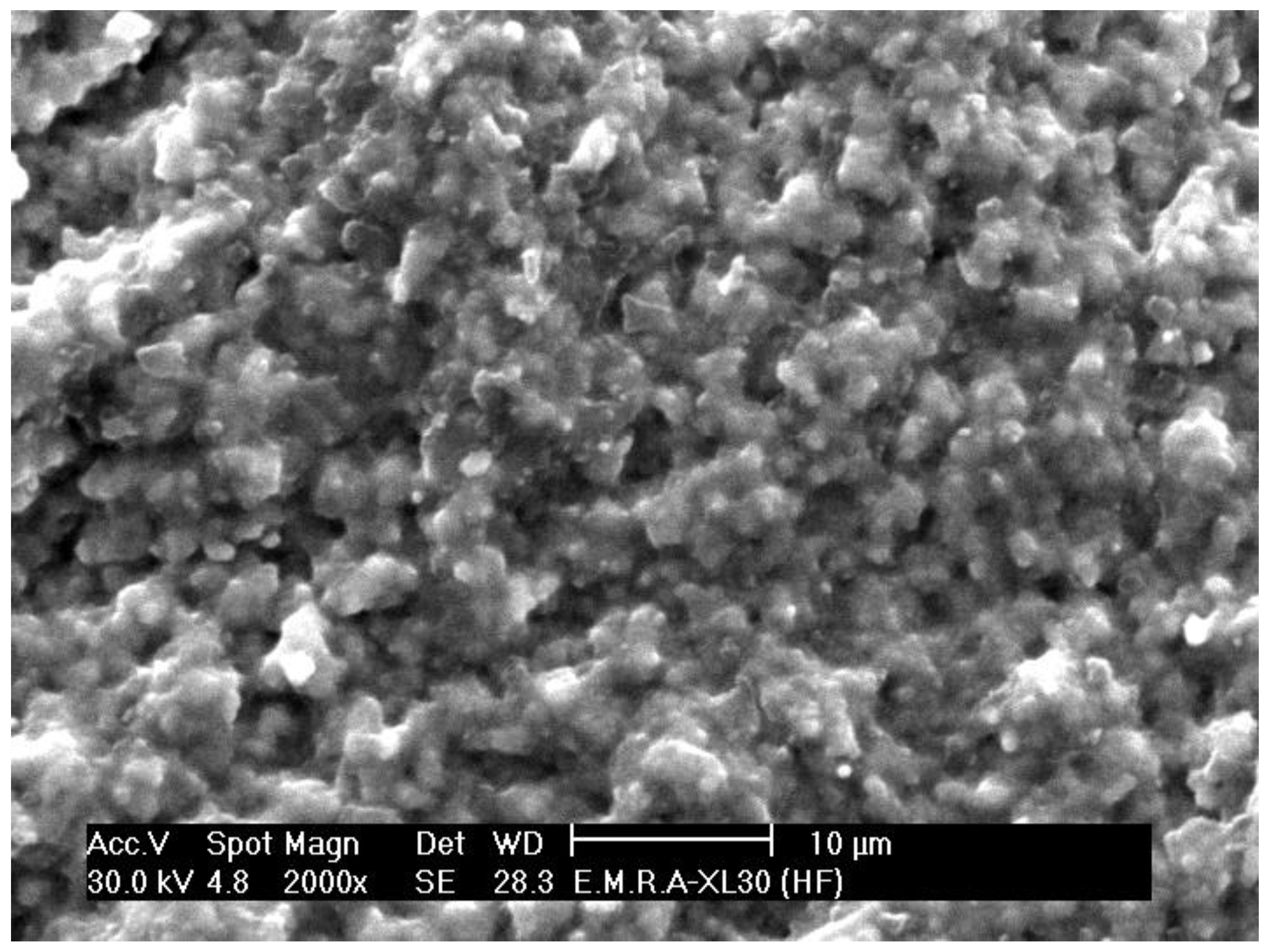
HF acid gel left during sintering (s.ttt. 1) resulted in an irregular zirconia surface, as seen in Figure 5 and Figure 6.
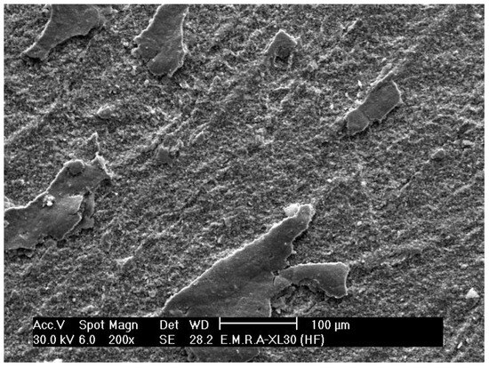
Figure 5.
SEM micrograph of sintered zirconia specimen, where HF was left during sintering. Top view, magnification: 200×.

Figure 6.
SEM micrograph of sintered zirconia specimen, where HF was left during sintering. Top view, magnification: 2000×.
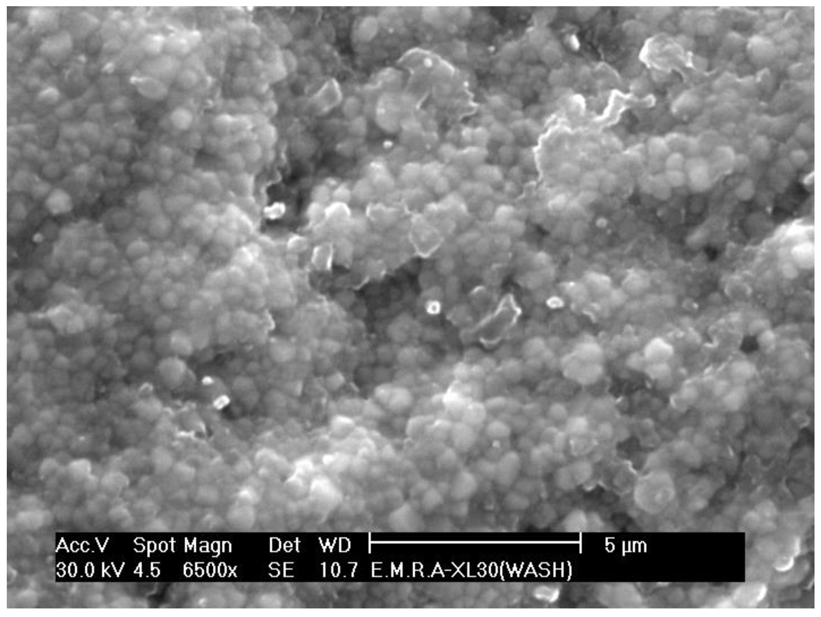
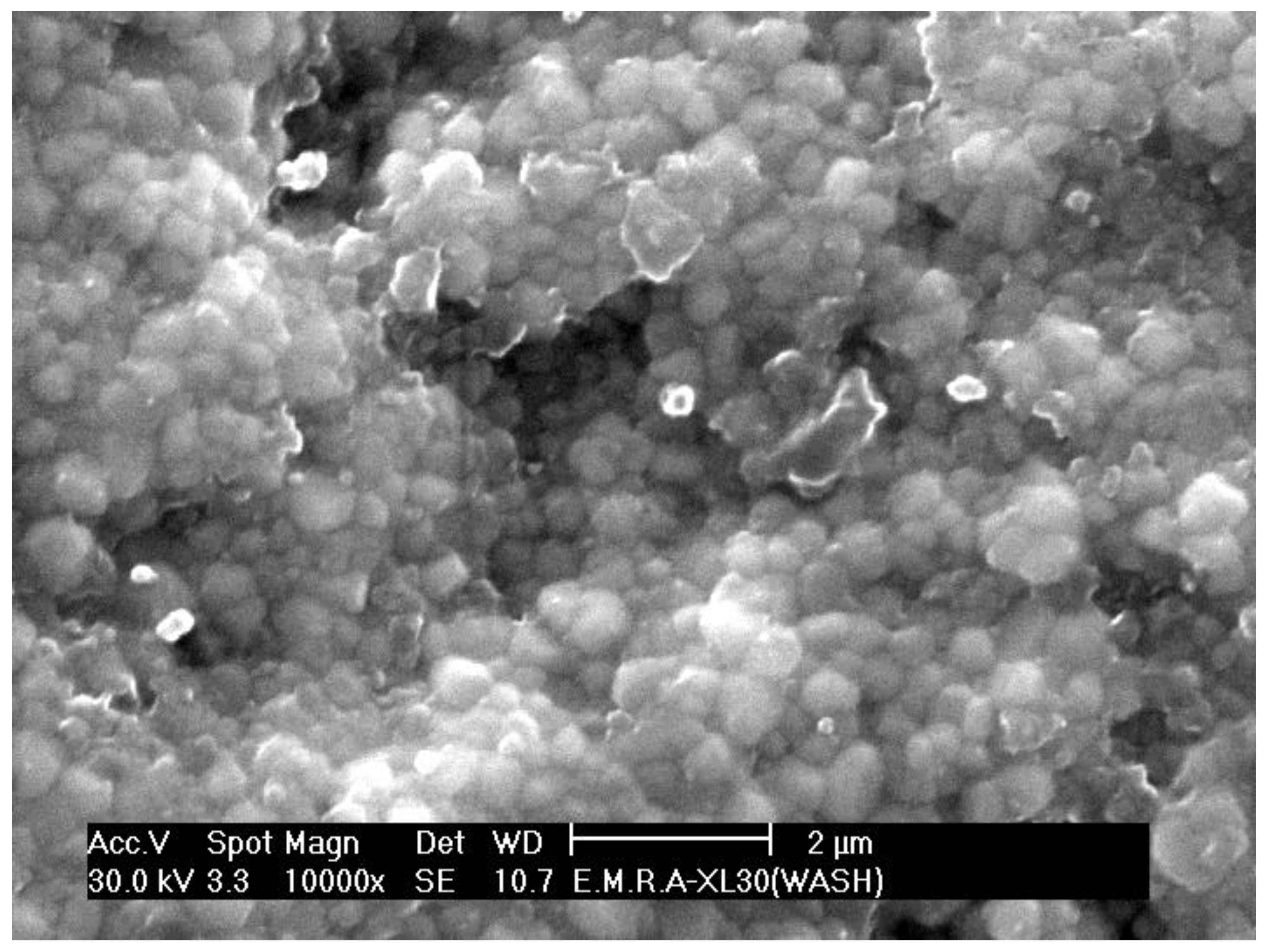
When the HF acidic gel was washed before sintering (s.ttt. 2), this also resulted in an irregular zirconia surface, as seen in Figure 7 and Figure 8.

Figure 7.
SEM micrograph of sintered zirconia specimen, where HF was removed before sintering. Top view, magnification: 6500×.

Figure 8.
SEM micrograph of sintered zirconia specimen, where HF was removed before sintering. Top view, magnification: 10,000×.
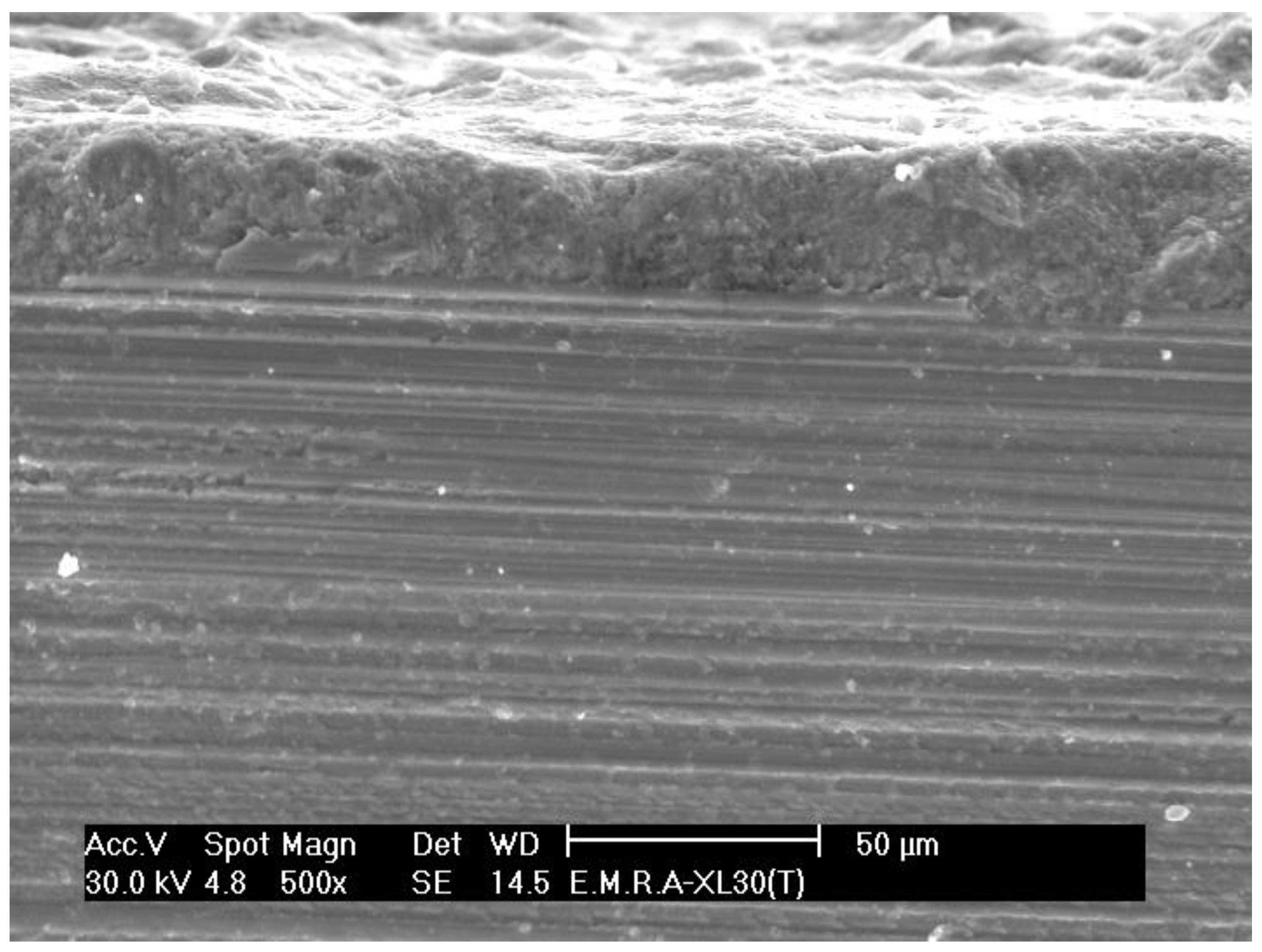
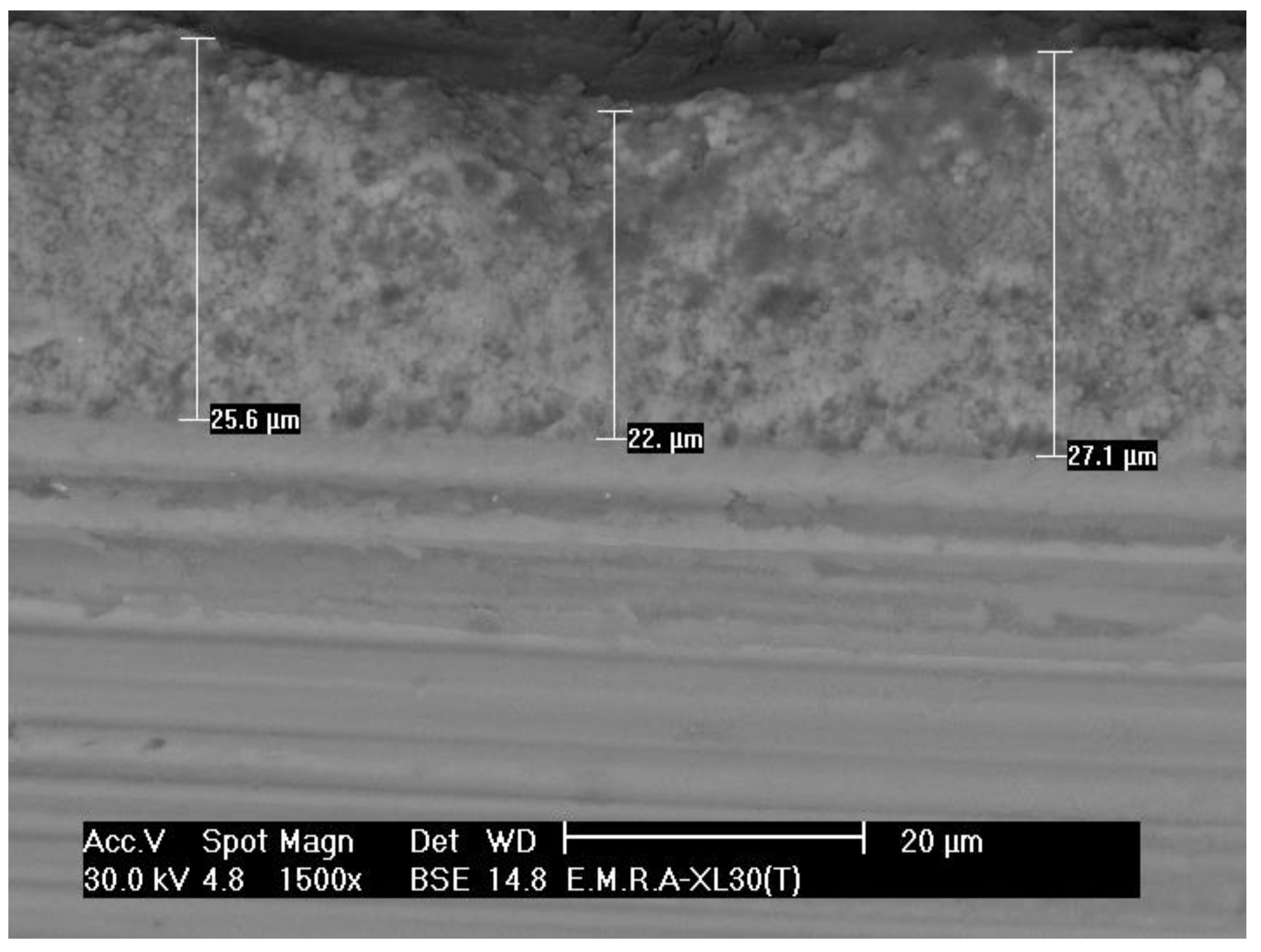
Applying nanosilica to presintered zirconia followed by sintering (s.ttt. 3) led to the deep penetration of the silica, up to 27 µm in depth, as shown in the lateral view of the treated specimens in Figure 9 and Figure 10.

Figure 9.
SEM micrograph of sintered zirconia specimen, where nanosilica was used in liquid form. Lateral view, magnification: 500×.
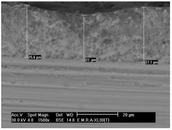
Figure 10.
SEM micrograph of sintered zirconia specimen, where nanosilica was used in liquid form. Lateral view, magnification: 1500×.
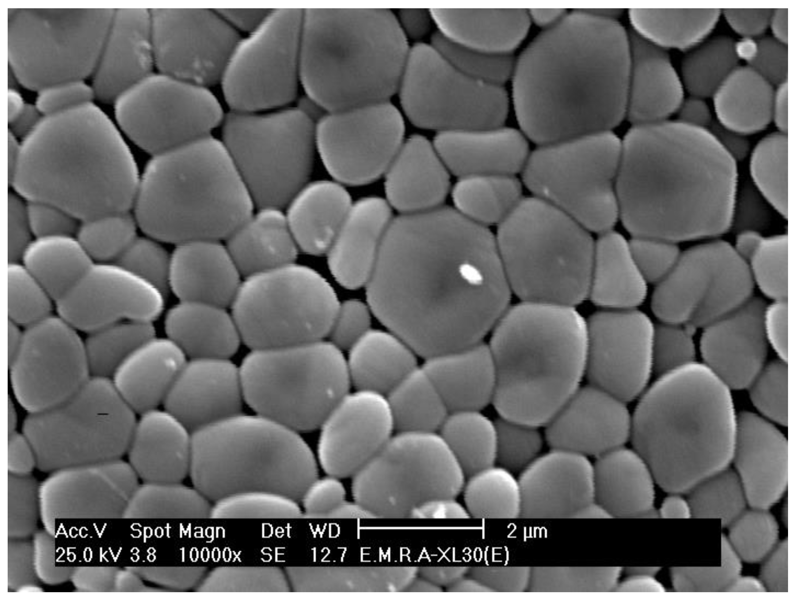
Using silica powder with the gel-forming agent on presintered zirconia followed by sintering (s.ttt. 4) resulted in the formation of a glassy layer over the zirconia grains (Figure 11) with no subsurface penetration, as shown in the lateral view in Figure 12.

Figure 11.
SEM micrograph of sintered zirconia specimen, where silica was used in powder form. Top view, magnification: 20,000×.
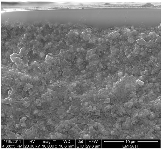
Figure 12.
SEM micrograph of sintered zirconia specimen, where nanosilica was used in powder form. Lateral view, magnification: 10,000×.
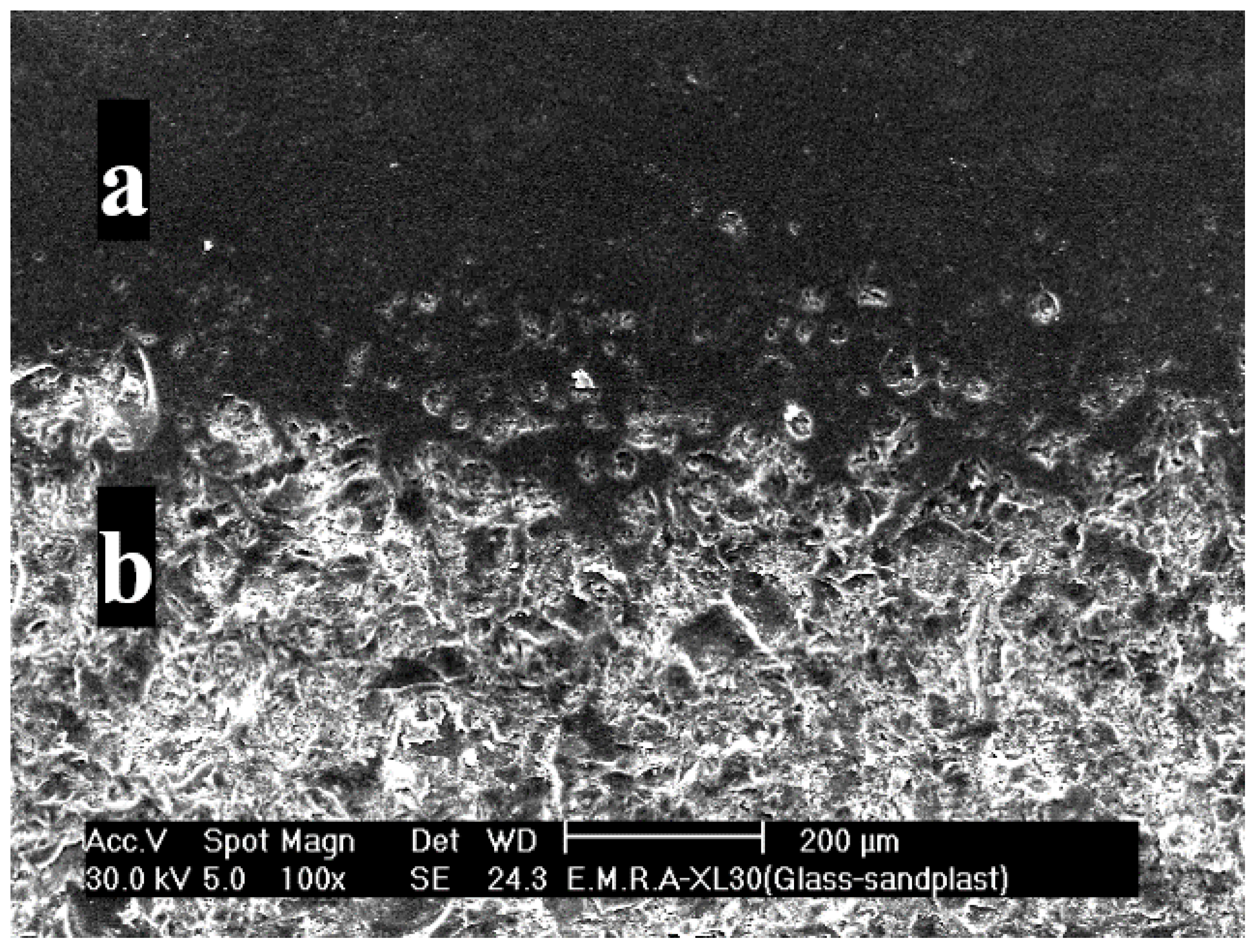
Coating the specimens followed by the airborne-particle abrasion of the coat (s.ttt. 5) revealed an abraded surface with surface irregularities, as shown in Figure 13. Figure 14 shows the change in the structure of the coat after abrasion, with Figure 14a showing the coat before abrasion and Figure 14b the coat after abrasion.
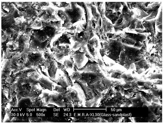
Figure 13.
SEM micrograph of coated zirconia specimen followed by airborne-particle abrasion. Top view, magnification: 500×.
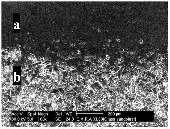
Figure 14.
SEM micrograph of coated zirconia specimen followed by airborne-particle abrasion. Top view, magnification: 100×. (a) Coat before abrasion; (b) coat after abrasion.
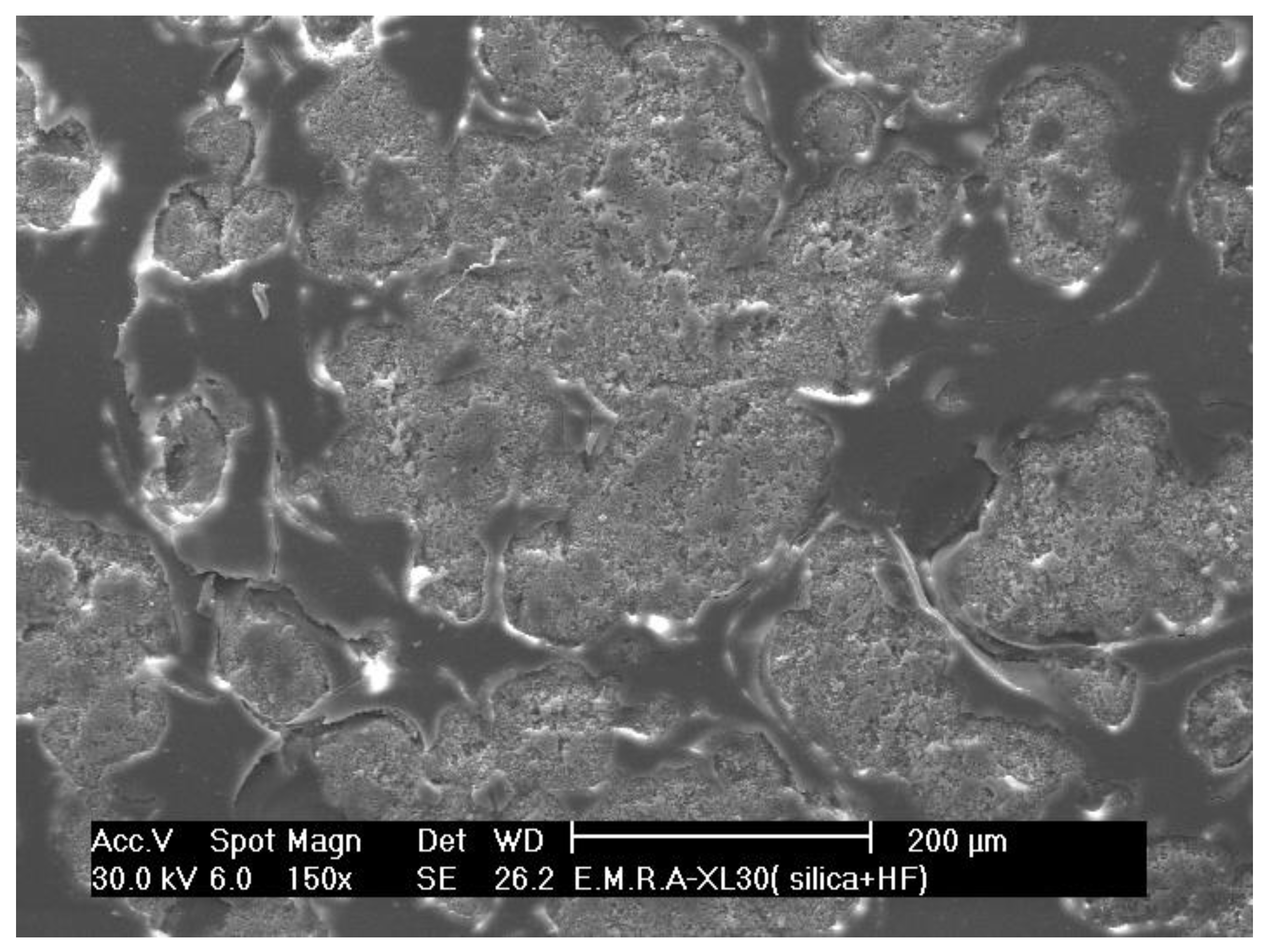
The partial etching of the coated zirconia (s.ttt. 6) revealed etched parts with irregularities, as shown in Figure 15 and Figure 16.

Figure 15.
SEM micrograph of coated zirconia specimen followed by partial etching of the silica. Top view, magnification: 150×.
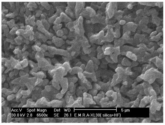
Figure 16.
SEM micrograph of coated zirconia specimen followed by partial etching of the silica. Top view, magnification: 6500×.
In the coated zirconia specimen followed by the complete etching of the coat (s.ttt. 7), imaging revealed intergranular spaces, as seen in Figure 17 and Figure 18.

Figure 17.
SEM micrograph of coated zirconia specimen followed by total etching of the silica. Top view, magnification: 10,000×.
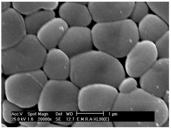
Figure 18.
SEM micrograph of coated zirconia specimen followed by total etching of the silica. Top view, magnification: 20,000×.
3.2. Crystalline Phase Identification
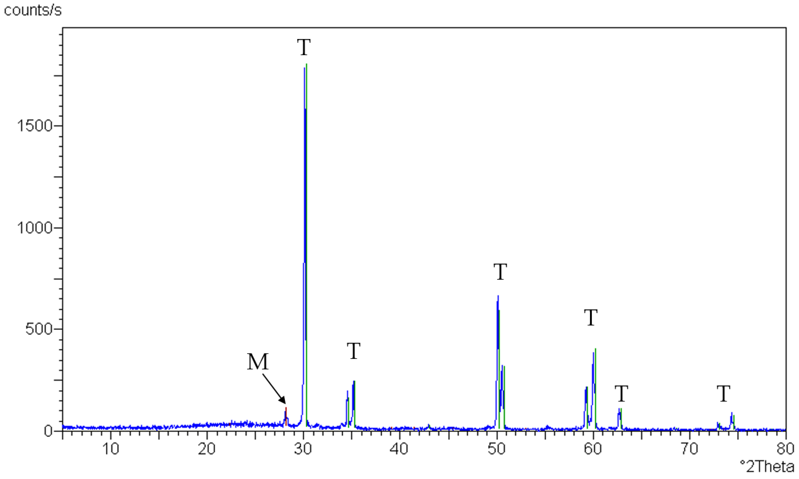
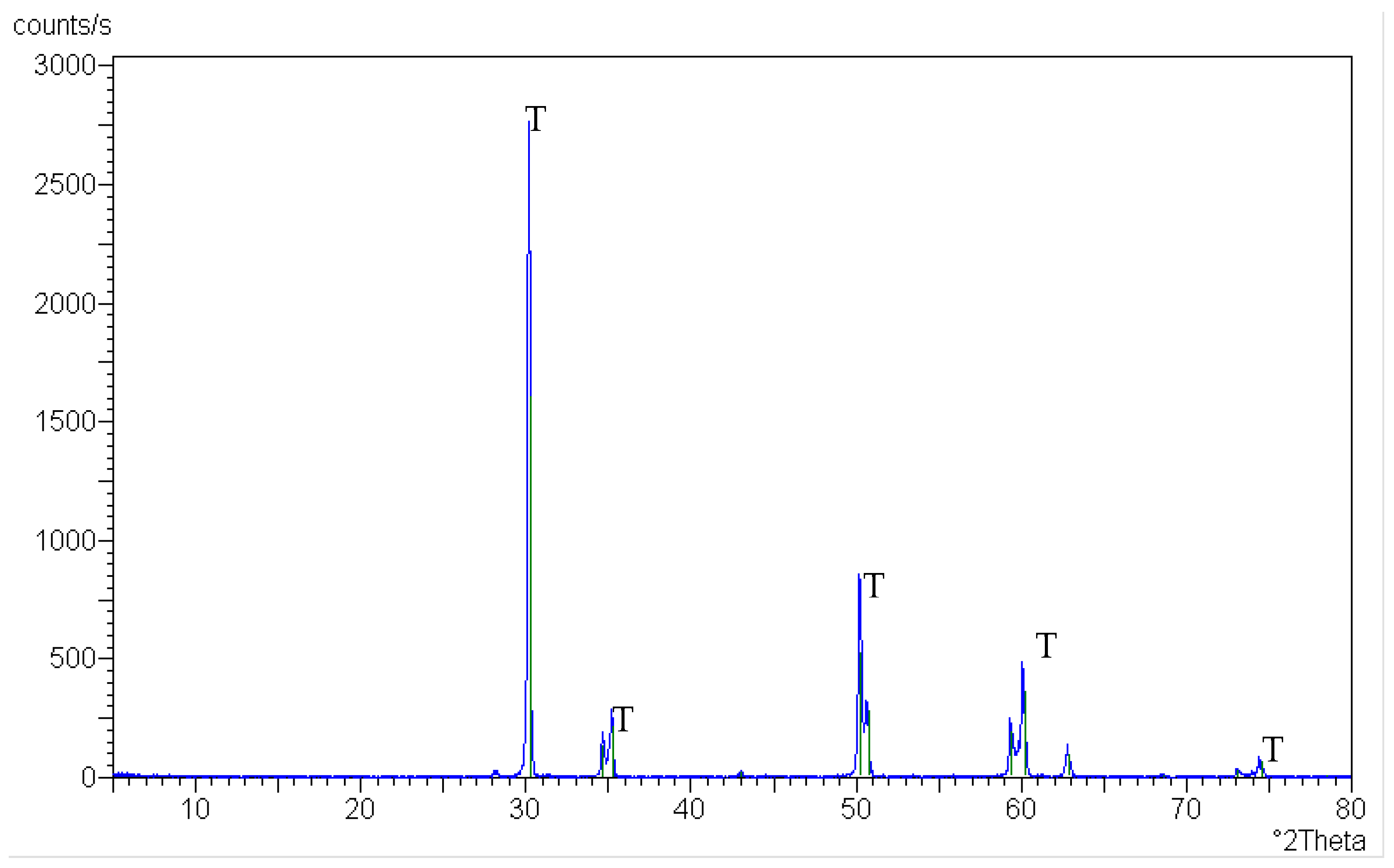
According to the XRD patterns, the presintered zirconia specimens revealed both a tetragonal phase (at 2°theta angles of 30.6, 34.9, 35.6, 50.6, 51, 59.7, 60.4, 63.1, 73.4, and 74.7) and a monoclinic phase (at a 2°theta angle of 28.6), as shown in Figure 19.
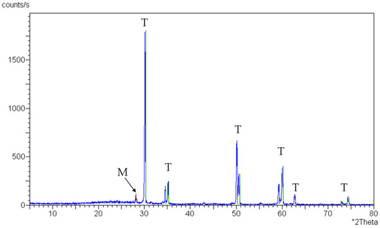
Figure 19.
XRD pattern of presintered zirconia specimen; green lines: peaks of tetragonal zirconia (T) and red line: peak of monoclinic zirconia (M).
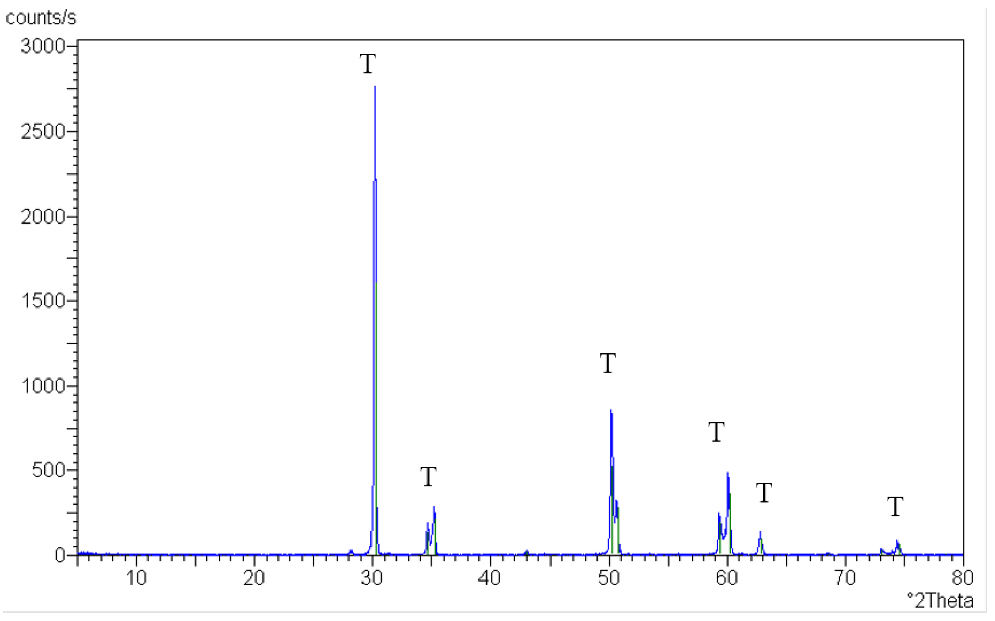
Tetragonal zirconia was only identified in the control sintered zirconia (without treatment) and after etching with HF gel (either partial or complete; s.ttt. 1 and 2) (at 2°theta angles of 30.6, 34.9, 35.6, 50.6, 51, 59.7, 60.4, 63.1, 73.4, and 74.7), as seen in Figure 20 and Figure 21.
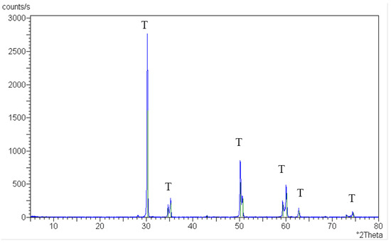
Figure 20.
XRD pattern of sintered control zirconia specimen (without treatment); green lines: peaks of tetragonal zirconia (T).
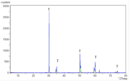
Figure 21.
XRD pattern of sintered zirconia specimen after etching with HF gel (either partial or complete); green lines: peaks of tetragonal zirconia (T).
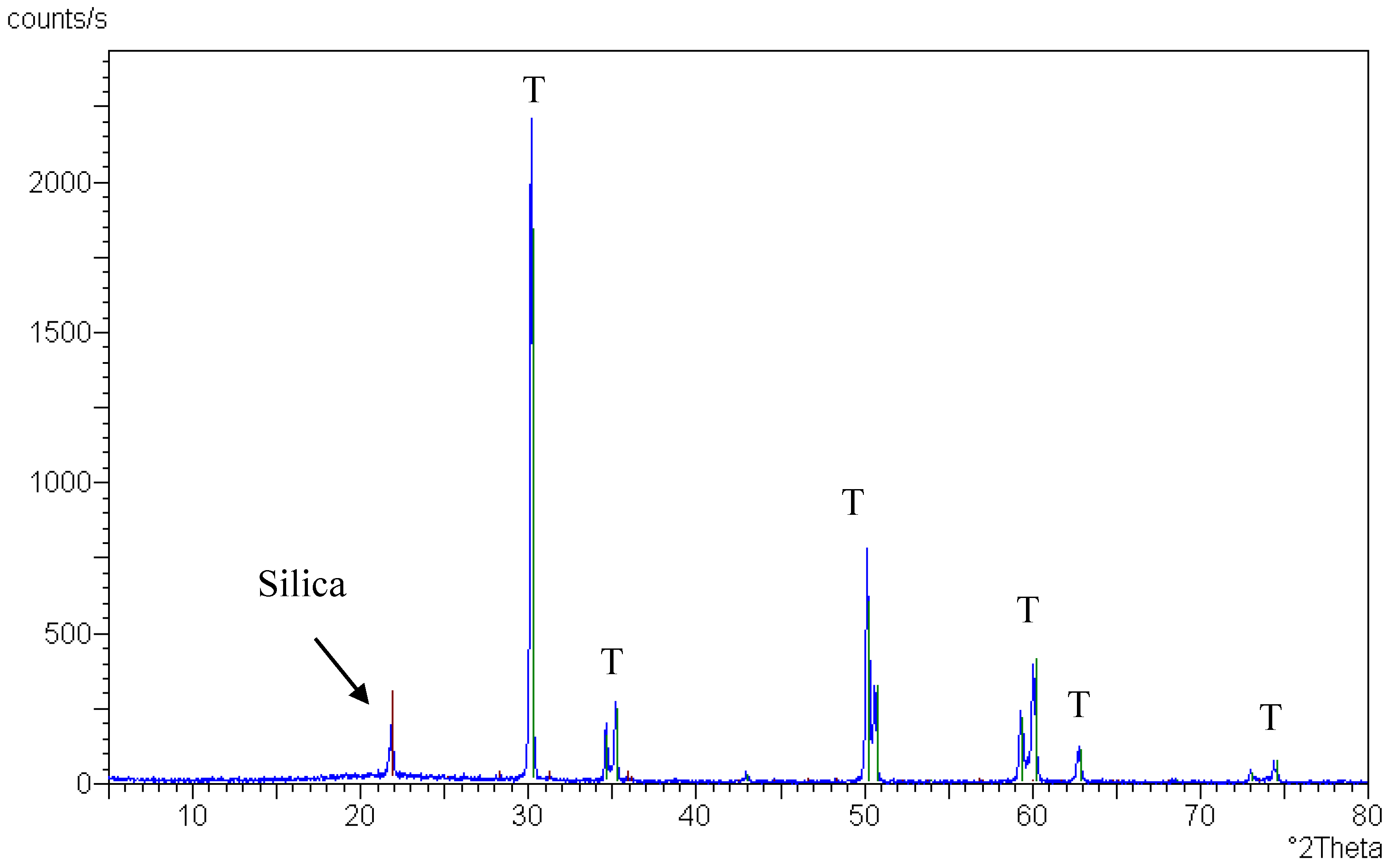
When using the nanosilica (either in the liquid or the powder form; s.ttt. 3 and 4), cristobalite silica (at a 2°theta angle of 21.8) and tetragonal zirconia (at the 2°theta angle previously mentioned) was detected after sintering, as seen in Figure 22. (Note: the crystallized silica resisted any etching trials.)
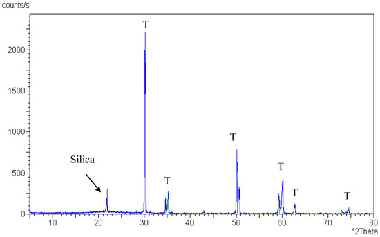
Figure 22.
XRD pattern of sintered zirconia specimen using nanosilica (either in liquid or powder form), red line: peak of cristobalite silica and green lines: peaks of tetragonal zirconia (T).
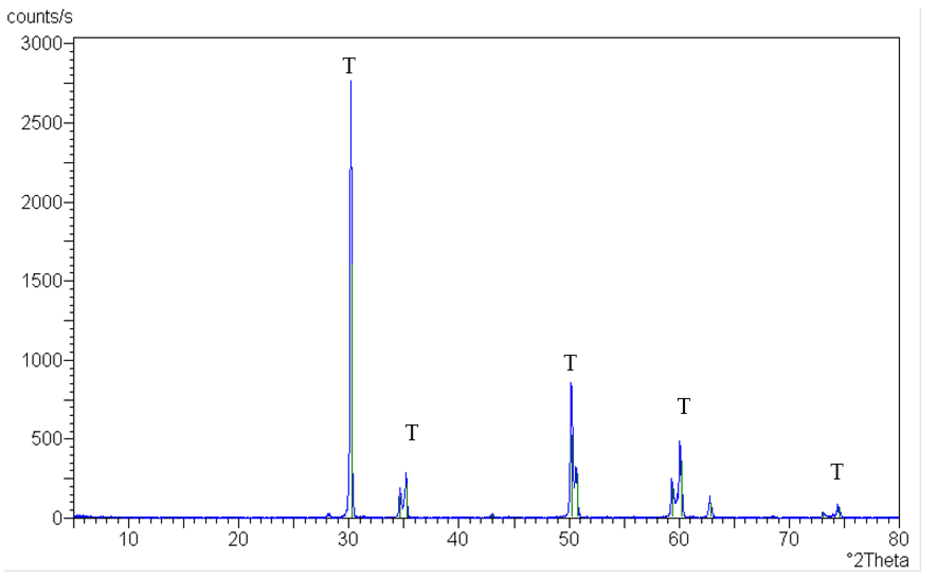
On the other hand, zirconia coated with neutral porcelain and subjected to airborne-particle abrasion or partial etching (s.ttt. 5 and 6) revealed tetragonal zirconia and amorphous silica (since no peaks were detected), as seen in Figure 23. (Note: this amorphous silica could be etched.)
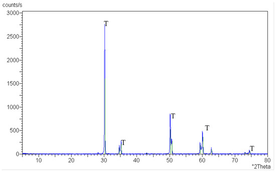
Figure 23.
XRD pattern of sintered zirconia coated with neutral porcelain; green lines: peaks of tetragonal zirconia (T).
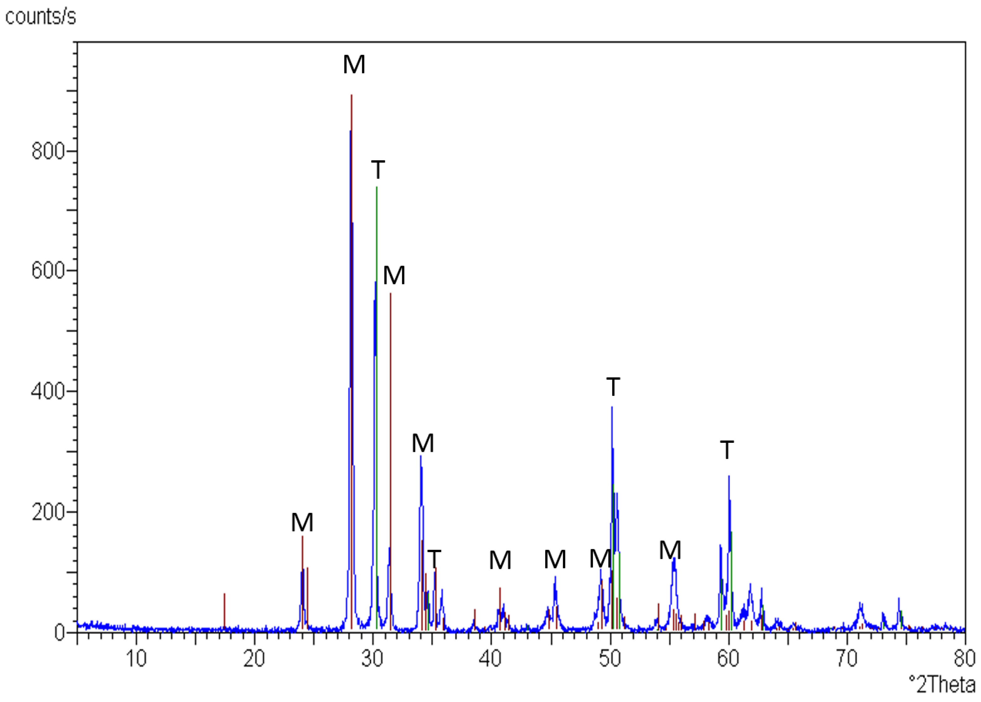
After the complete etching of the silica (s.ttt. 7), several monoclinic zirconia peaks appeared (the highest peaks were at 2°theta angles of 24, 28.6, 31.8, and 34.1), as seen in Figure 24.
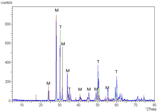
Figure 24.
XRD pattern of sintered zirconia specimen after complete etching of the silica; red line: peaks of monoclinic zirconia (M) and green lines: peaks of tetragonal zirconia (T).
3.3. Flexural Strength
The results for biaxial flexural strength (MPa) are presented in Table 2. The highest flexural strength was for s.ttt. 4, coated with microsilica (982.3 MPa), while the lowest one was for s.ttt. 7 (386.6 MPa), which was subjected to total coat removal by acid.
Table 2.
Biaxial flexural strength (MPa).
There was no significant difference in flexural strength between the control and s.ttt. 1 and 2 (846.3, 830, and 835 MPa, respectively). Compared to the control group, the nanosilica-coated specimens (s.ttt. 3) had a lower flexural strength (634.1 MPa), while sttt. 5 and 6 (with roughened coats) had higher flexural strengths (863.1 and 872.2 MPa, respectively) than the control group.
4. Discussion
Zirconia is a ceramic material with unique characteristics that allow it to be used in dental restorations and implants. However, establishing a strong, stable bond with zirconia is difficult due to its inertness and acid resistance [19]. Several surface treatments have been proposed to modify the surface to aid in bonding [20]. However, the material is liable to be weakened by aggressive surface treatments [19]. This research was conducted to modify the zirconia surface in its presintered state using seven different surface treatments and compare them to an untreated control. The null hypothesis was rejected as there were differences between the control and treated groups.
In the SEM observations, presintered zirconia showed a porous structure, which was obviously reduced in the control group (C) due to the sintering process. The HF acid gel left during sintering (s.ttt. 1) or HF treatment with washing before sintering (s.ttt. 2) resulted in an irregular zirconia surface. Although zirconia is a non-silica-based ceramic, it is not etched by HF at normal temperature, yet it is feasible to etch a zirconia surface at high temperatures [21]. The HF that remained during sintering was heated, and so could have etched the surface then. However, there should not have been HF on the surface during sintering in s.ttt. 2. In this case, it may be that HF was able to etch the presintered zirconia in a way that prevented the creation of a smooth surface. Further research is needed to determine the mechanism here.
Applying nanosilica to presintered zirconia followed by sintering (s.ttt. 3) led to a deep penetration of the silica up to 27 µm in depth. This may be due to the nanosize of the silica that entered the porosity of the presintered zirconia and became trapped between the grains during the grains. The SEM of the microsilica-treated group (s.ttt. 4) showed a glassy coat upon the zirconia surface with limited penetration due to the larger silica particles compared to s.ttt. 3. A previous study coated the zirconia in its presintered state with a zirconia slurry with carbon nanoparticles [18].
In the abraded or partially etched coat (s.ttt. 5 and 6), surface flaws were detected because of airborne abrasion and etching, which caused irregularities within the coat. On the other hand, the complete etching of the coat (s.ttt. 7) revealed intergranular spaces. Complete etching of the infiltrating glass has been previously presented but in sintered zirconia, called the selective infiltration etching technique [17].
The crystalline structure of the presintered zirconia specimens, revealed with XRD, showed the presence of the monoclinic phase in addition to the tetragonal one. This agrees with Tsalouchou et al. [22], who found that zirconia powder before sintering included tetragonal and monoclinic phases. However, this finding contradicts that of Moon et al. who stated that presintered zirconia ceramics consisted of almost 100% tetragonal structures [23].
After sintering, only the tetragonal phase was identified in the control group. This result is consistent with both Tsalouchou E et al. and Moon JE et al., who noted that there were no monoclinic structures in as-sintered Y-TZP [22,23]. This might be explained by the monoclinic–tetragonal phase transformation induced by the sintering temperature, with an end temperature of 1530 °C [16]. It is known that heating zirconia above 1170 °C induces a phase transformation from monoclinic to tetragonal [16]. Most surface treatments (s.tttt. 1-6) displayed tetragonal zirconia, as in the control [16]. This means that these modifications did not affect the crystalline phase. On the other hand, the aggressive etching in s.ttt. 7 led to a phase transition from tetragonal to monoclinic, which caused material deterioration [24].
It should be noted that amorphous silica could be etched, in contrast to crystalline silica (cristobalite), which resisted any etching procedure. This may be due to the random arrangement of atoms in the amorphous structure, which does not require as much energy to react with acids [25].
Flexural strength defines how materials reacted to loading forces [26]. Flexural strength is a crucial mechanical characteristic that can help predict the performance of a material [26]. The size of flaws and defects present on the surface of a tested material have a significant impact on its flexural strength [27]. The biaxial flexural strength test was employed in this investigation due to its advantages over the other tests [28]. In comparison to three- or four-point flexural tests, the biaxial flexural test is less sensitive to edge effects and to surface flaws brought on by specimen preparation [29]. Three- and four-point bend tests are most sensitive to faults that are almost perpendicular to the specimen’s beam axis, but the biaxial test probes for the greatest flaws oriented over a wider range of angles [29].
The highest flexural strength was for s.ttt. 4 coated with microsilica (982.3 MPa). This may be attributed to the presence of an intact coat, which required additional force to fracture, in addition to the sealing of any existing flaws by the glassy layer [30]. This was followed by s.ttt. 5 and 6 (with roughened coats), which had higher flexural strengths (863.1 and 872.2 MPa, respectively) than the control but lower ones than s.ttt. 4. This may be due to the strengthening effect of the coat [31], but because of the irregularities within the coat, it showed a lower flexural strength than the intact coat in s.ttt. 4 [32]. This was followed by the control and s.ttt. 1 and 2 (846.2, 830, and 835 MPa, respectively), with no significant difference in their flexural strengths (p = 0.1), as these treatments did not induce a monoclinic phase transformation [32]. It was reported previously in the literature that a significant loss of flexural strength occurred in zirconia treated in its presintered state by airborne-particle abrasion due to monoclinic phase transformation [33].
In this study, it was observed that two surface treatments weakened the flexural strength of zirconia: deep subsurface silica penetration or monoclinic phase transformation. The nanosilica-coated specimens (s.ttt. 3) had a lower flexural strength (634.1 MPa) than the control group (846.3 MPa). This may be attributed to the deep penetration of the silica, even though there was no monoclinic phase transformation [32]. The presence of silica between the zirconia grains led to a lower flexural strength as the mechanical properties of silica are lower than those of tetragonal zirconia. The lowest flexural strength (386.6 MPa) was for the surface treatment accompanied by a monoclinic phase transformation (s.ttt. 7), which was subjected to total coat removal by acid [32]. This may be due to the lower mechanical properties of the monoclinic phase compared to the tetragonal phase, as described previously [32,34]. The phase transformation may be due to low-temperature degradation in an acid environment, as a previous study reported that an acidic environment accelerates the tetragonal to monoclinic phase change of yttrium-stabilized zirconia [33].
The last-mentioned two surface treatments (s.ttt. 3 and 7) are not recommended as they reduced the flexural strength. The other five treatments could be beneficial as they preserved the high flexural strength of zirconia and formed a rough surface or coat. It has been reported that the surface roughness of dental implants, especially nanoroughness, encourages undifferentiated mesenchymal cell attachment, proliferation, and differentiation to osteoblasts. However, this study did not apply cells and did not measure the surface roughness after treatment. Therefore, these points should be studied in future work. In addition, the coated specimens could reduce the low-temperature degradation of zirconia implants and orthopedic appliances and need further investigation. Other research could be conducted to determine whether the incorporation of bioactive material within the roughness could stimulate biointegration. It is also recommended to add bond strength tests to future studies to investigate the effect of these pretreatments on their bonding to different substructures.
5. Conclusions
The treatment of a presintered zirconia surface can successfully create a rough surface on the sintered material. However, treatments that result in the deep penetration of silica, or that promote a phase change from tetragonal to monoclinic, also substantially weaken the material and should be avoided. This approach is promising, but the surface treatment must be carefully specified to avoid negative effects on material properties.
6. Patents
International Application Published under the Patent Cooperation Treaty (PCT), entitled: Presintered Zirconia Surface Treatment Technique for Dental Appliances. International Publication Number WO 2012/171535A1.
Author Contributions
Conceptualization, R.M.A., M.A. and N.A.H.; methodology, R.M.A., M.A. and N.A.H.; validation, R.M.A., N.A.H., T.M.H. and A.A.; formal analysis, R.M.A. and N.A.H.; investigation, R.M.A. and N.A.H.; data curation, R.M.A. and N.A.H.; writing—original draft preparation, R.M.A., N.A.H., A.A. and T.M.H.; writing—review and editing, R.M.A., N.A.H., T.M.H., A.A., C.A.J. and A.T.; visualization, R.M.A. and N.A.H.; supervision, M.A., R.M.A. and N.A.H. All authors have read and agreed to the published version of the manuscript.
Funding
This research was funded by Researchers Supporting Project number (RSPD2023R790), King Saud University, Saudi Arabia, Riyadh.
Data Availability Statement
The corresponding author can provide the data described in this study upon request.
Acknowledgments
The authors are grateful to the Researchers Supporting Project number (RSPD2023R790), King Saud University, Riyadh, Saudi Arabia. We would like also to thank “Bee Chems Company” for providing the nanosilica (Dentex Bee Chems, India).
Conflicts of Interest
The authors declare no conflict of interest.
References
- Grech, J.; Antunes, E. Zirconia in dental prosthetics: A literature review. J. Mater. Res. Technol. 2019, 8, 4956–4964. [Google Scholar] [CrossRef]
- Habib, A.W.; Aboushelib, M.N.; Habib, N.A. Effect of chemical aging on color stability and surface properties of stained all-ceramic restorations. J. Esthet. Restor. Dent. 2021, 33, 636–647. [Google Scholar] [CrossRef]
- Hamdy, T.M. Polymers and ceramics biomaterials in orthopedics and dentistry: A review article. Egypt. J. Chem. 2018, 61, 723–730. [Google Scholar] [CrossRef]
- Comba, A.; Paolone, G.; Baldi, A.; Vichi, A.; Goracci, C.; Bertozzi, G.; Scotti, N. Effects of substrate and cement shade on the translucency and color of CAD/CAM lithium-disilicate and zirconia ceramic materials. Polymers 2022, 14, 1778. [Google Scholar] [CrossRef] [PubMed]
- Alqutaibi, A.Y.; Ghulam, O.; Krsoum, M.; Binmahmoud, S.; Taher, H.; Elmalky, W.; Zafar, M.S. Revolution of current dental zirconia: A comprehensive review. Molecules 2022, 27, 1699. [Google Scholar] [CrossRef] [PubMed]
- Rizky, N.S.; Rikmasari, R.; Bonifacius, S. Evaluation of zirconia surface roughness after different surface treatment with sandblasting, hydrofluoric acid etching, and combination treatment. Key Eng. Mater. 2022, 932, 163–169. [Google Scholar] [CrossRef]
- Hamdy, T.M. Interfacial microscopic examination and chemical analysis of resin-dentin interface of self-adhering flowable resin composite. F1000Research 2017, 6, 1688. [Google Scholar] [CrossRef]
- Tzanakakis, E.G.C.; Tzoutzas, I.G.; Koidis, P.T. Is There a potential for durable adhesion to zirconia restorations? A systematic review. J. Prosthet. Dent. 2016, 115, 9–19. [Google Scholar] [CrossRef]
- Nicolas-Silvente, A.I.; Velasco-Ortega, E.; Ortiz-Garcia, I.; Monsalve-Guil, L.; Gil, J.; Jimenez-Guerra, A. Influence of the titanium implant surface treatment on the surface roughness and chemical composition. Materials 2020, 13, 314. [Google Scholar] [CrossRef]
- Delgado-Ruíz, R.A.; Calvo-Guirado, J.L.; Moreno, P.; Guardia, J.; Gomez-Moreno, G.; Mate-Sánchez, J.E.; Ramirez-Fernández, P.; Chiva, F. Femtosecond laser microstructuring of zirconia dental implants. J. Biomed. Mater. Res.-Part B Appl. Biomater. 2011, 96, 91–100. [Google Scholar] [CrossRef]
- Tzanakakis, E.; Kontonasaki, E.; Voyiatzis, G.; Andrikopoulos, K.; Tzoutzas, I. Surface characterization of monolithic zirconia submitted to different surface treatments applying optical interferometry and raman spectrometry. Dent. Mater. J. 2020, 39, 111–117. [Google Scholar] [CrossRef]
- Hallmann, L.; Ulmer, P.; Reusser, E.; Hämmerle, C.H.F. Effect of Blasting Pressure, Abrasive Particle Size and Grade on Phase Transformation and Morphological Change of Dental Zirconia Surface. Surf. Coat. Technol. 2012, 206, 4293–4302. [Google Scholar] [CrossRef]
- Iinuma, Y.; Hirota, M.; Hayakawa, T.; Ohkubo, C. Surrounding tissue response to surface-treated zirconia implants. Materials 2020, 13, 30. [Google Scholar] [CrossRef] [PubMed]
- Li, R.; Chen, H.; Wang, Y.; Sun, Y. Performance of stereolithography and milling in fabricating monolithic zirconia crowns with different finish line designs. J. Mech. Behav. Biomed. Mater. 2021, 115, 104255. [Google Scholar] [CrossRef]
- Maridurai, T.; Balaji, D.; Sagadevan, S. Synthesis and characterization of yttrium stabilized zirconia nanoparticles. Mater. Res. 2016, 19, 812–816. [Google Scholar] [CrossRef]
- Bona, A.D.; Pecho, O.E.; Alessandretti, R. Zirconia as a Dental Biomaterial. Materials 2015, 8, 4978–4991. [Google Scholar] [CrossRef]
- Aboushelib, M.N.; Kleverlaan, C.J.; Feilzer, A.J. Selective infiltration-etching technique for a strong and durable bond of resin cements to zirconia-based materials. J. Prosthet. Dent. 2007, 98, 379–388. [Google Scholar] [CrossRef]
- Jo, Y.-B.; Ahn, J.-J.; Lee, S.-H.; Park, T.; Huh, J.-B. The effect of ZrO2 slurry application to the pre-sintered zirconia surface on bonding strength. Korean Acad. Oral Maxillofac. Implantol. 2020, 24, 76–82. [Google Scholar] [CrossRef]
- Peçanha, M.; Amaral, M.; Baroudi, K.; Frizzera, F.; Vitti, R.; Silva-Concilio, L. Improving the bonding stability between resin cements and zirconia-based ceramic using different surface treatments. Int. J. Prosthodont. 2022, 35, 414–419. [Google Scholar] [CrossRef]
- Melo, R.M.; Souza, R.O.A.; Dursun, E.; Monteiro, E.B.C.; Valandro, L.F.; Bottino, M.A. Surface treatments of zirconia to enhance bonding durability. Oper. Dent. 2015, 40, 636–643. [Google Scholar] [CrossRef]
- Kim, S.H.; Cho, S.C.; Lee, M.H.; Kim, H.J.; Oh, N.S. Effect of 9% hydrofluoric acid gel hot-etching surface treatment on shear bond strength of resin cements to zirconia ceramics. Medicine 2022, 58, 1469. [Google Scholar] [CrossRef] [PubMed]
- Tsalouchou, E.; Cattell, M.; Knowles, J.; Pittayachawan, P.; Mcdonald, A. Fatigue and fracture properties of yttria partially stabilized zirconia crown systems. Dent. Mater. 2008, 24, 308–318. [Google Scholar] [CrossRef]
- Moon, J.; Kim, S.; Lee, J.; Ha, S.; Choi, Y. The effect of preparation order on the crystal structure of yttria-stabilized tetragonal zirconia polycrystal and the shear bond strength of dental resin cements. Dent. Mater. 2011, 27, 651–663. [Google Scholar] [CrossRef] [PubMed]
- Ruyter, E.I.; Vajeeston, N.; Knarvang, T.; Kvam, K. A Novel etching technique for surface treatment of zirconia ceramics to improve adhesion of resin-based luting cements. Acta Biomater. Odontol. Scand. 2017, 3, 36–46. [Google Scholar] [CrossRef]
- Borouni, M.; Niroumand, B.; Maleki, A. A Study on crystallization of amorphous nano silica particles by mechanical activation at the presence of pure aluminum. J. Solid State Chem. 2018, 263, 208–215. [Google Scholar] [CrossRef]
- Tsujimoto, A.; Irie, M.; Teixeira, E.C.N.; Jurado, C.A.; Maruo, Y.; Nishigawa, G.; Matsumoto, T.; Garcia-Godoy, F. Relationships between flexural and bonding properties, marginal adaptation, and polymerization shrinkage in flowable composite restorations for dental application. Polymers 2021, 13, 2613. [Google Scholar] [CrossRef]
- Tsujimoto, A.; Barkmeier, W.W.; Takamizawa, T.; Latta, M.A.; Miyazaki, M. Depth of cure, flexural properties and volumetric shrinkage of low and high viscosity bulk-fill giomers and resin composites. Dent. Mater. J. 2017, 36, 205–213. [Google Scholar] [CrossRef] [PubMed]
- Itinoche, K.M.; Özcan, M.; Bottino, M.A.; Oyafuso, D. Effect of mechanical cycling on the flexural strength of densely sintered ceramics. Dent. Mater. 2006, 22, 1029–1034. [Google Scholar] [CrossRef] [PubMed]
- Miura, D.; Ishida, Y.; Miyasaka, T.; Shinya, A.; Aoki, H. Reliability of different bending test methods for dental press ceramics. Materials 2020, 13, 5162. [Google Scholar] [CrossRef]
- Liu, R.; Sun, T.; Zhang, Y.; Zhang, Y.; Jiang, D.; Shao, L. The effect of graded glass-zirconia structure on the bond between core and veneer in layered zirconia restorations. J. Mech. Behav. Biomed. Mater. 2015, 46, 197–204. [Google Scholar] [CrossRef] [PubMed]
- Kaimal, A.; Ramdev, P.; Shruthi, C.S. Evaluation of effect of zirconia surface treatment, using plasma of argon and silane, on the shear bond strength of two composite resin cements. J. Clin. Diagn. Res. 2017, 11, ZC39–ZC43. [Google Scholar] [CrossRef] [PubMed]
- Daou, E.E. The zirconia ceramic: Strengths and weaknesses. Open Dent. J. 2014, 8, 33–42. [Google Scholar] [CrossRef] [PubMed]
- Kurtulmus-Yilmaz, S.; Aktore, H. Effect of the application of surface treatments before and after sintering on the flexural strength, phase transformation and surface topography of zirconia. J. Dent. 2018, 72, 29–38. [Google Scholar] [CrossRef]
- Gąsiorek, J.; Mazur-Nowacka, A.; Szczurek, A.; Babiarczuk, B.; Tic, W.J.; Guziałowska-Tic, J.; Kaleta, J.; Krzak, J. Influence of zirconia and organic additives on mechanical and ectrochemical properties of silica sol-gel coatings. Materials 2021, 14, 2389. [Google Scholar] [CrossRef] [PubMed]


Disclaimer/Publisher’s Note: The statements, opinions and data contained in all publications are solely those of the individual author(s) and contributor(s) and not of MDPI and/or the editor(s). MDPI and/or the editor(s) disclaim responsibility for any injury to people or property resulting from any ideas, methods, instructions or products referred to in the content. |
© 2023 by the authors. Licensee MDPI, Basel, Switzerland. This article is an open access article distributed under the terms and conditions of the Creative Commons Attribution (CC BY) license (https://creativecommons.org/licenses/by/4.0/).