Article

The Impact of Hole Diameter on the Molded and Drilled Holes in Jute-Fiber-Reinforced Epoxy Composites

1
Department of Mechanical Engineering, Katihar Engineering College, Katihar 854109, India
2
Department of Mechanical and Industrial Engineering, Indian Institute of Technology Roorkee, Roorkee 247667, India
3
Department of Mechanical Engineering, National Institute of Technology Uttarakhand, Srinagar 246174, India
4
Mechanical Engineering Department, University of Aveiro, 3810-193 Aveiro, Portugal
*
Author to whom correspondence should be addressed.
J. Compos. Sci. 2023, 7(9), 376; https://doi.org/10.3390/jcs7090376
Submission received: 6 August 2023 / Revised: 24 August 2023 / Accepted: 6 September 2023 / Published: 8 September 2023
(This article belongs to the Special Issue Feature Papers in Journal of Composites Science in 2023)

Abstract

:
Damage caused by the drilling process is the most common reason for the rejection of composite parts and components that include holes. This is especially true in the case of laminated composites. The purpose of the current experimental investigation is to investigate the efficiency of hole formation when the component is in the molding phase. The mechanical properties of molded and drilled holes in jute-fiber-reinforced epoxy composites have been compared in a study that was carried out with the purpose of conducting an examination of these features. It was discovered that the molded holes operate much better than the drilled holes when it comes to jute fiber/epoxy composite materials. This was the conclusion reached after observing both types of holes. The maximum tensile load that was taken by molded hole specimens of composites with hole diameters of 4 mm and 8 mm was reported to be 48.8% and 101.5% greater, respectively, than the maximum tensile load that was taken by drilled hole specimens of composites with the same diameter. In addition, the load-extension curves demonstrate that the specimens that were manufactured with molded holes were able to achieve a larger degree of extension when compared to those that were manufactured with drilled holes.

1. Introduction

Natural-Fiber-Reinforced Composites (NFRCs) represent an important category of materials that has the capacity to contribute towards the worldwide objectives of sustainability and environmental preservation. In order to maximize the potential of polymer matrix composite materials, it is essential to establish their high quality and cost-effective processing. While the basic production techniques for producing products based on NFRCs have reached a high level of commercialization, additional research efforts are needed to advance knowledge regarding their secondary manufacturing processes, specifically in the areas of machining and joining. The composite materials are extensively being used in product development. Based on existing methods of fabrication, no method is available for a complete product development process. If these materials are going to be used in any product development, they need secondary operations such as hole making or drilling [1,2,3]. Mechanical joining is one of the best methods of joining two similar or dissimilar types of materials. It provides assembly, disassembly, and easy maintenance of the joints [4,5,6]. The basic requirement of mechanical joining is producing a hole in the adherends for fixing the fastener. The generation of holes requires machining operations such as drilling, punching, and slotting. The drilling process is commonly used for hole making in different types of materials, but the hole-drilling operation in laminated composite materials is a difficult task. Polymer matrix composites are non-homogenous and anisotropic materials [7,8,9]. Their properties vary throughout the thickness of materials. Therefore, it is very difficult to select an optimum process parameter for the drilling of polymer matrix composites. The process of drilling in laminated composite materials results in several flaws, including delamination of the peel-up and push-down type, fractures, fiber pull-out, and fiber burning [10,11,12]. Delamination in composites was observed by Venkateshwaran et al. [13], with the extent of delamination being influenced by process factors, such as cutting speed, feed rate, and drill shape and drill shape materials. When the feed rate and cutting speed increase, there is a corresponding increase in the delamination behavior. In addition to this, the issue of tool wear is a significant concern that arises throughout the process of the drilling of laminated composite materials. The drilling process performed at a sub-optimal parametric setting also increases the magnitude of the thrust force exerted in the case of composite materials. Singh et al. [14] found that the thrust force is influenced by both the feed rate and drill geometry. The augmentation of both the feed rate and the drill tip angle results in an elevation of the thrust force magnitude. In order to reduce the thrust force during the drilling of polymer matrix composites, different tool geometries were used. Debnath et al. [15] found that the parabolic drill tool provides low thrust force and torque as compared to step- and four-facet drill tools. Drilling parameters also depend on the types of reinforcing materials and matrix materials. In that case, it is very difficult to optimize the process parameters for the drilling of each combination of reinforcing and matrix materials [16,17,18]. Therefore, researchers have used a hole-molding operation during the composite fabrication process to produce the hole in laminated composite materials. Numerous tests and analyses have been conducted to evaluate and compare the performance characteristics of molded and drilled holes in synthetic-fiber-reinforced polymer composites. According to the findings of Chang et al. [19], the failure strength of molded hole composites exhibited superior performance compared to that of drilled hole composites. The absence of fiber cutting in the hole-molding process may be attributed to the use of continuous fibers. Yau et al. [20] conducted an experimental investigation to examine the performance of open hole testing in carbon-fiber-reinforced polymer composites (with both molded and drilled holes). The findings of the study revealed that the molded hole composites exhibited superior strength in comparison to the composites with drilled holes. Nejhad et al. [21] conducted an investigation to assess the compressive strength of carbon-fiber-reinforced polymer composites with molded and drilled hole configurations. The findings of the study revealed that the compressive strength of specimens with molded holes was found to be better as compared to specimens with drilled holes. The strength of the composite specimens under loading was attributed to the presence of continuous fiber surrounding the hole. Langella et al. [22] observed that specimens with holes created by the shifting of fibers had a better tensile strength compared to specimens with holes created by punching and drilling procedures. All of the research was conducted using synthetic-fiber-reinforced polymer composites as the primary focus of the investigation. Recent years have seen a surge in the number of studies that concentrate on the creation of natural-fiber-reinforced composites. An exciting area of study interest is the possibility of using natural-fiber-reinforced composite materials rather than synthetic-fiber-reinforced composites to strengthen composite materials. Both of these materials exhibit considerably distinct responses to a wide range of stress conditions, each in its own unique way. As a consequence of this, the findings of the experiments conducted with synthetic fiber composites may not be immediately comparable to those conducted with natural-fiber-reinforced composites. On the subject of the behavior of the hole-molding effect with regard to drilling in natural-fiber-reinforced polymer composite materials, only a few publications are currently accessible. As a consequence of this, a recent study examination was carried out. It is possible for the molding process to cut down on the amount of secondary processing that must be done before composite pieces may be mechanically fastened. During the step of the product development cycle known as primary manufacturing, the holes might be created, if necessary.
Presently, researchers from numerous fields, including science and engineering, are focusing their attention on the possibility of using natural fibers in place of synthetic fibers in a variety of products with both structural and non-structural applications. As a consequence of this, both the scientific community and the policies of the government are lobbying for the use of natural fibers. Jute is produced in greater quantities in India than any other country. Because of this, the use of jute fibers in the manufacturing process of composites that include the reinforcing of natural fibers inside polymer matrices is rather common. The manufacture of composite materials relies heavily on the process of linking the various component parts together. In order to explore the effect that hole diameter has on the tensile strength of composite laminates, specimens with molded and drilled holes were constructed with sizes of 4 mm and 8 mm, respectively. In addition, the joint strength of molded and drilled hole specimens with a diameter of 4 mm was measured and analyzed for a lap joint arrangement.

2. Material and Methods

2.1. Raw Materials

Go Green in Chennai, India provided the woven jute fiber that was purchased by the company. Before the manufacture of polymer composites, the fibers were cleaned and then allowed to dry in the sunshine. These fibers were used in the production of composite materials as reinforcement. After the dirt had been removed from the fiber mat, it was cleaned and then dried in the sun for a period of two days. The mat was preheated in an oven at a temperature of 90 °C before the composite was made. Epoxy was decided upon as the substance for the matrix. It was packaged in two separate containers. Both the liquid resin (Make: Araldite (LY556)) and the hardener (Araldite (HY953)) were contained inside two separate containers. One of the containers held liquid resin. In order to ensure that the epoxy cured correctly, the manufacturer recommended using a volume ratio of 100:10 when combining the resin and the hardener.

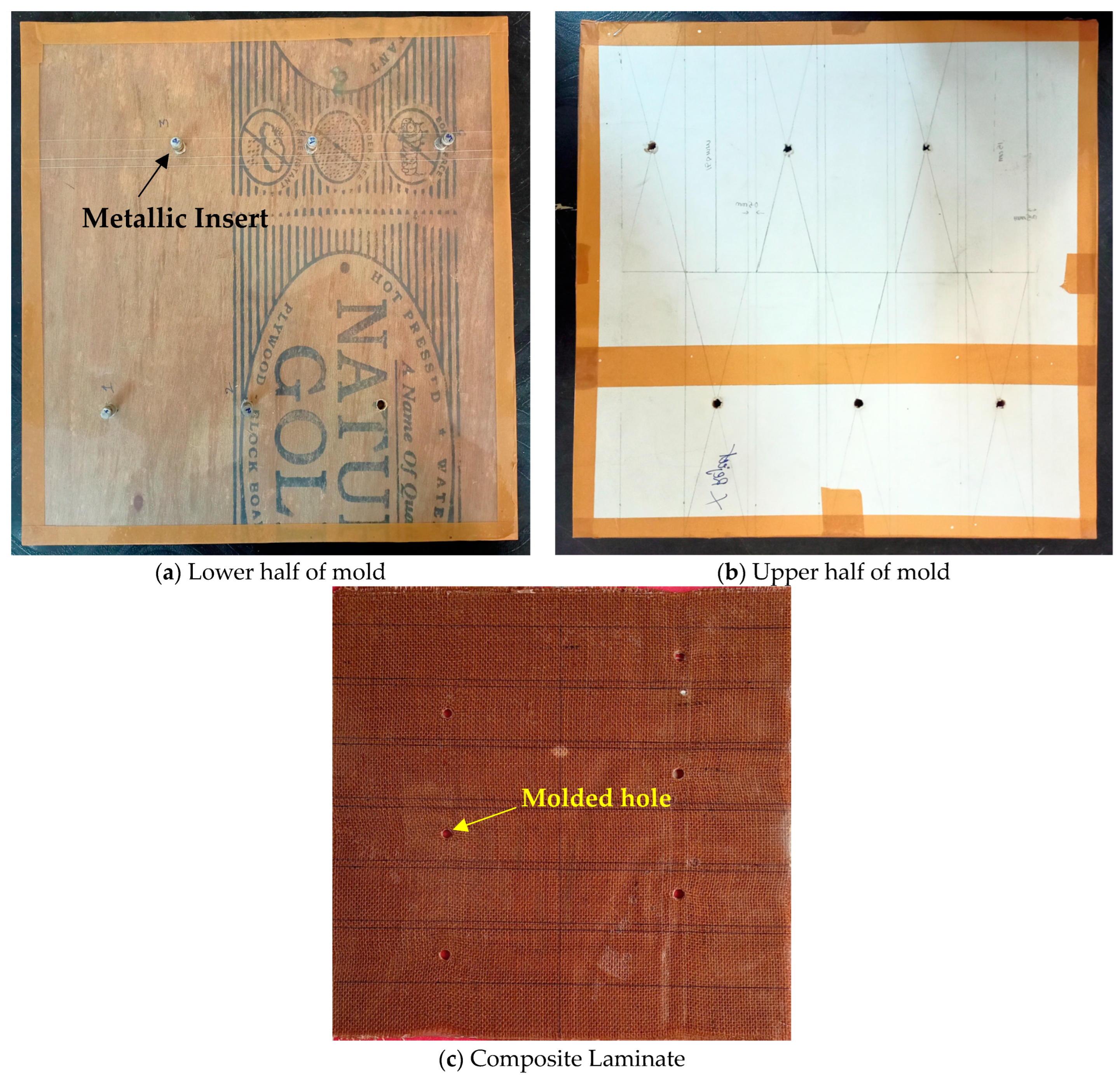
2.2. Specimen Preparation

Two wooden plies measuring 2 × 2 sq. feet were selected as mold materials. The mold utilized for the manufacture of composite laminates is shown in Figure 1a. For the purpose of manufacturing molded holes in composite laminates, metallic inserts were employed. Blind holes were bored into the bottom portion of the mold so that the inserts could be secured in place. In order to prevent matrix material from sticking to inserts and wooden molds before they were placed in holes, inserts were wrapped in plastic, and wooden molds were covered in plastic. After that, inserts were secured in the bottom part of the mold that had been previously prepared. In order to ensure that the holes were properly aligned, through-holes had to be drilled in the upper half of the mold in the same place as the hole that had been made in the lower half of the mold. Epoxy, which is a combination of resin and hardener, was placed on top of the fiber mat after it had been cut to the size specified by the mold. During the manufacturing process of composite laminates, a total of four layers of fiber mat were used. During the process of placing the fiber mat, some fibers were moved by hand near the inserts in order to facilitate the creation of the molded hole. Additionally, epoxy-impregnated fiber layers were covered with the upper half of the mold, and a dead weight load of 50 kg was applied to the top of the upper half of the mold in order to ensure that the composite laminate was properly compacted. After leaving everything in place for twenty-four hours, the matrix material was allowed to cure at room temperature, according to the manufacturer's instructions. After the curing process was complete, the composite laminates were removed from the mold, as can be seen in Figure 1b. Both a 4 mm and 8 mm diameter hole were molded into composite laminates before they were produced. Molded hole specimens were created by cutting the manufactured composite laminates, while drilled hole specimens were created by drilling specimens cut from the fabricated composite laminate. Both types of specimens were used in the study. In order to prevent delamination, a drilling operation was carried out using a radial drilling machine with a spindle speed of 3000 rpm and a feed rate of 0.05 mm/rev. The maker of the machine was Batliboi Pvt. Ltd., which is located in Surat, India. Table 1 presents the nomenclature of the specimens. The lap joint was made using a 4 mm mild steel nut and bolt assembly.
In order to assess the maximum tensile load that each individual specimen was capable of supporting during the loading process, an open hole test was carried out on each kind of specimen. In the course of these tests, the length, breadth, and thickness of the specimen were determined to be 150 mm, 25 mm, and 4 mm, respectively (in accordance with ASTM D 5766). The diameter of the holes that were molded and those that were drilled were both subjected to variation so that the impact of the hole size could be evaluated. The universal testing machine (UTM) was used to carry out the evaluations. The loading rate ended up being set at 2 mm per min.

3. Results and Discussion

The method of creating holes in composite materials is almost always a difficult operation. Several drilling-induced flaws in composite materials may be traced back to the anisotropic and inhomogeneous structure of composite laminates [23,24,25]. Researchers from all across the globe have discussed the difficulties that might arise while drilling composite materials. The most typical types of defects that may be caused by drilling include fiber pull-out, push-down type delamination, fractures, and sharp edges surrounding the hole. As a consequence of this, it is imperative to explore and create a technique for producing a hole in a composite material that is free from defects. As a result, the technique of hole drilling was contrasted with the procedure of hole molding in order to identify the superior option. It was discovered that the quality of the molded hole specimens was higher than the quality of the drilled hole specimens. The molded and drilled hole specimens are shown in Figure 2a through 2h. In the instance of the hole that was generated by the molding procedure, there were no uncut fibers, sharp edges, or fractures. In addition, the molding procedure required the holes to be round. However, in the case of specimens with drilled holes, fiber pull-out and push-down types of delamination, as well as fractures, were discovered close to the holes. The smooth and uncluttered surface was also visible on the cut section of the specimen of the molded hole. In addition, an uneven surface, fiber pull-out, and fractures were discovered in the case of cut sections of specimens obtained from drilled holes. In addition to this, it was discovered that the shifting action of the fibers generated by the metallic inserts led to a larger concentration of fibers in the area close to the molded hole sample. The strength of the composite material is affected positively as well as negatively by the high concentration of fibers in the material. During the process of manufacturing, the effect is beneficial if the fibers are impregnated by the matrix material in the appropriate manner. When there is a load placed on the structure, the fibers will take part in the load-bearing process. If the fibers are not correctly impregnated, they will function as stress concentration zones and have the potential to bring about the premature failure of the composite laminate when it is loaded.
The two different methods of creating holes each have their advantages and disadvantages. In one scenario, the poor quality of the hole is caused by drilling-induced damage, and in another scenario, the poor quality of the impregnation of fibers may be caused by a large concentration of displaced fibers surrounding the molded hole. Because of this, specimens produced using both techniques were subjected to further testing to see how they behaved mechanically. In order to determine the impact that the hole diameter has, specimens of two different diameters were created.

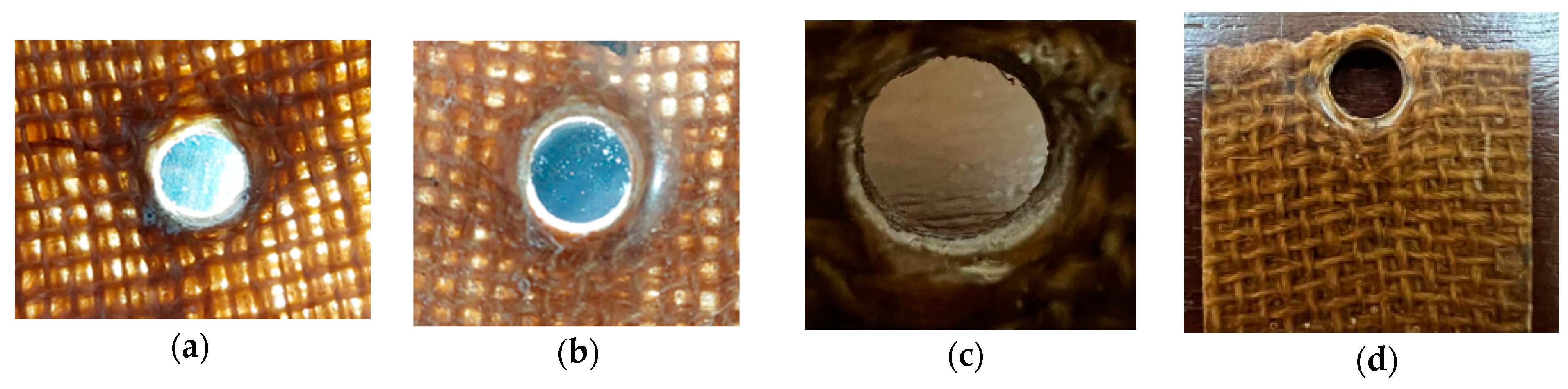
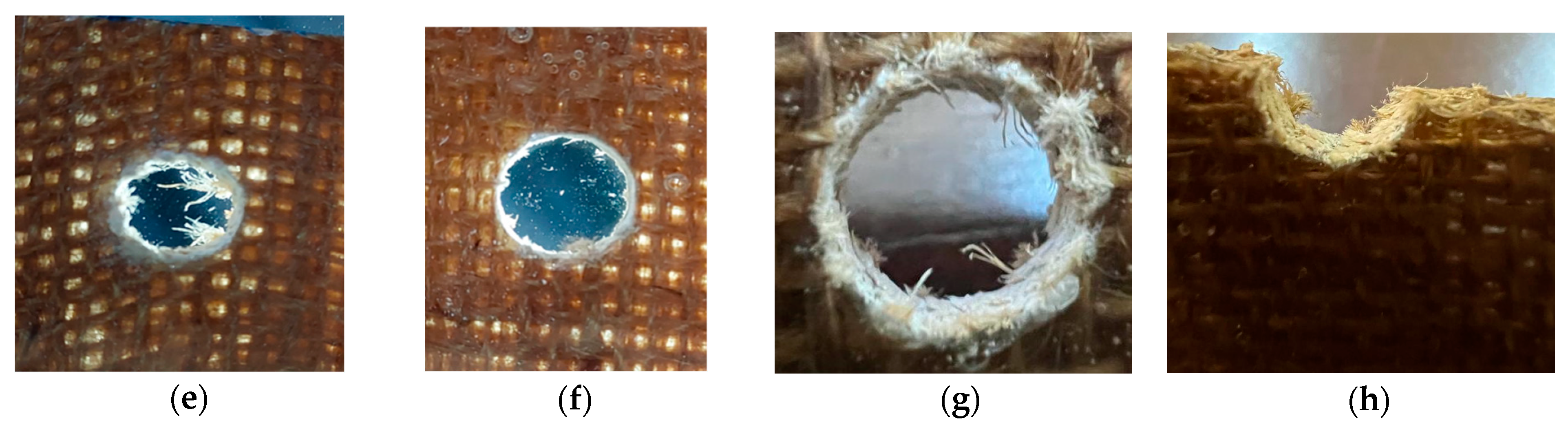
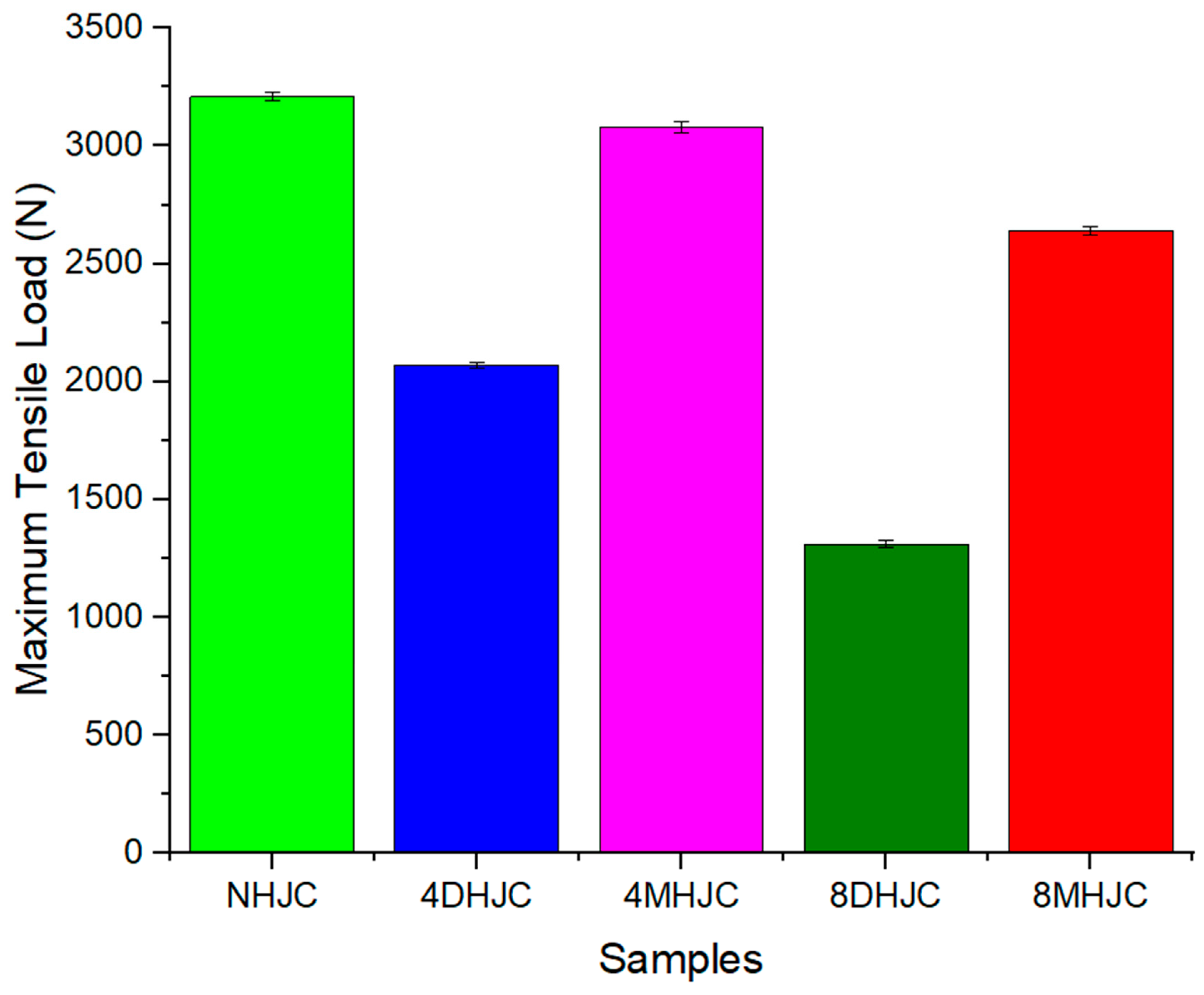
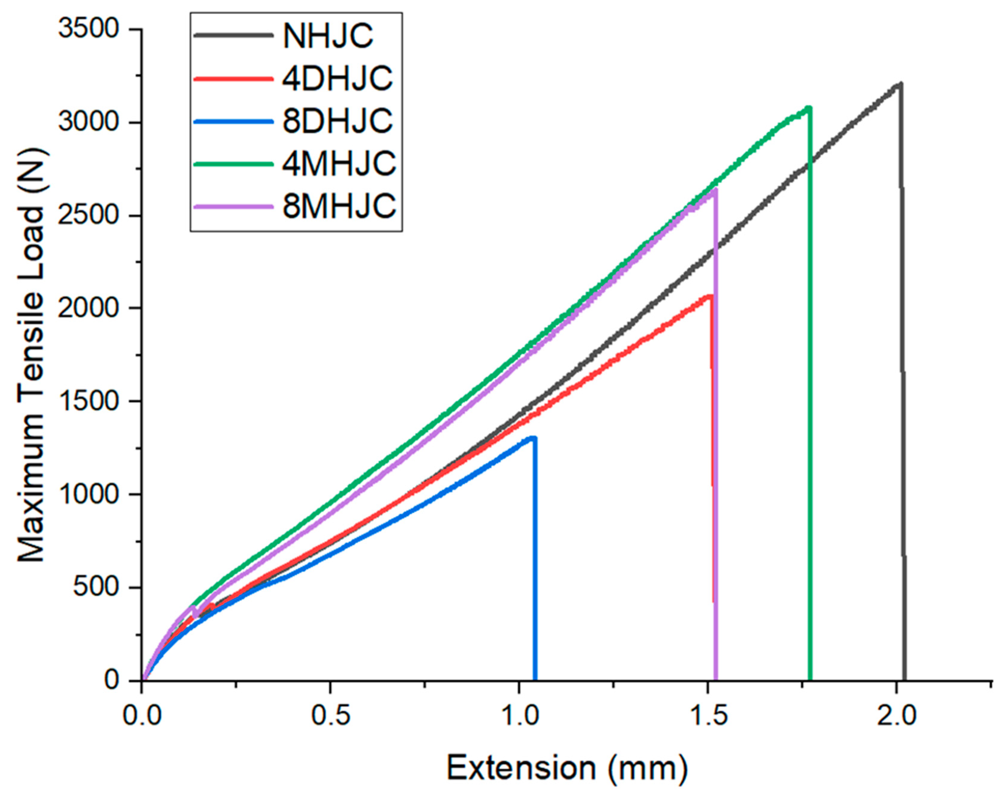
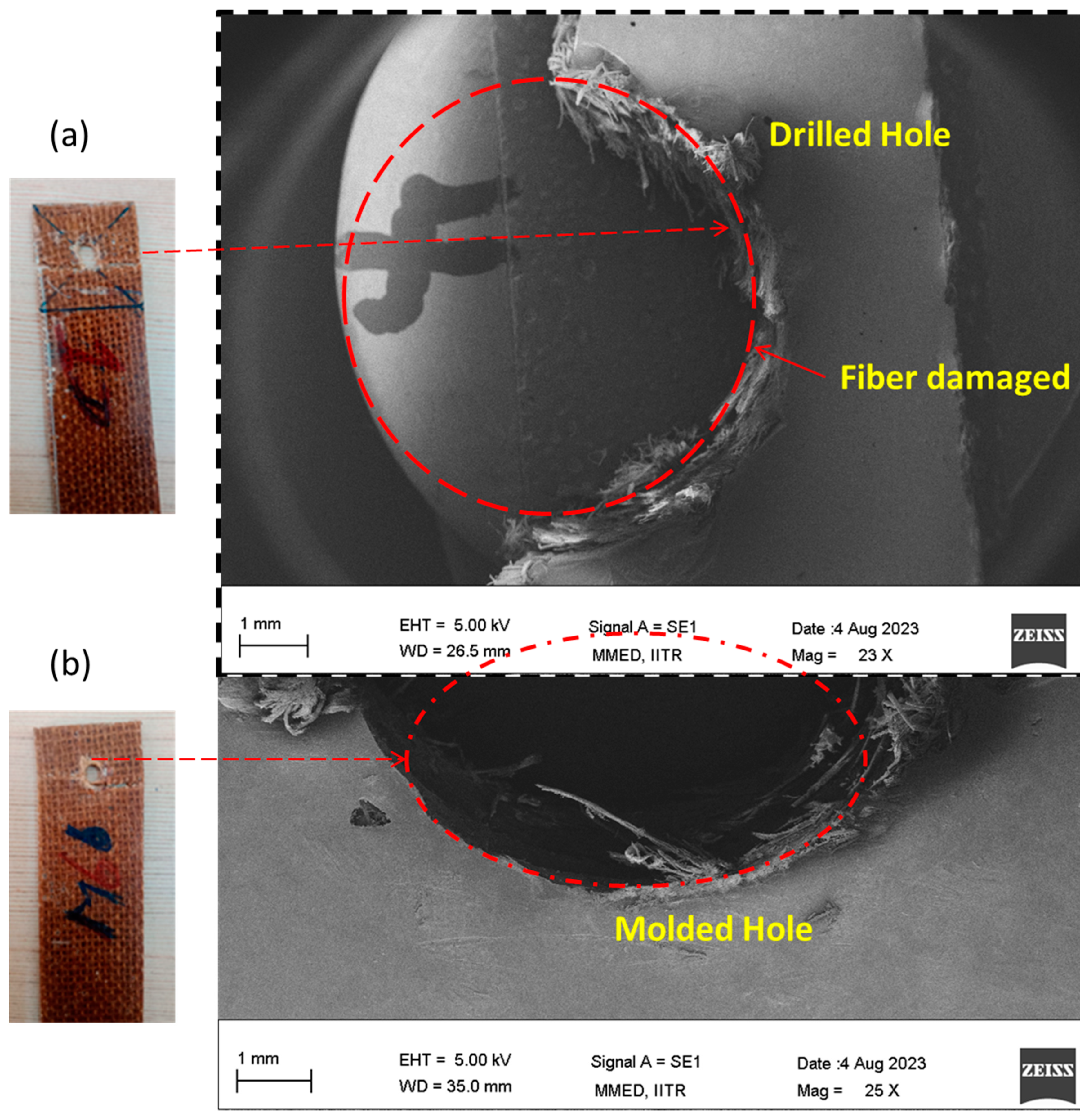
3.1. Open Hole Testing

The specimen was securely clamped inside the jaws of a universal testing machine, and a tensile load was then applied. Figure 3 illustrates the highest tensile load that the molded and drilled hole specimens were able to withstand prior to failure. It was found that the molded hole specimens had a greater capacity to withstand tensile load as compared to the drilled hole specimens, regardless of hole diameter. When comparing the specimens without a hole (NHJC) with those of 4MHJC and 8MHJC, it was observed that the latter two exhibited a reduction of 4.04% and 21.6%, respectively, in the amount of tensile load sustained prior to failure. The specimens labeled as 4MHJC and 8MHJC exhibited failure load values that were 48.8% and 101.5% higher, respectively, as compared to the failure load values recorded for the 4DHJC and 8DHJC specimens. The increased failure load values in the case of molded hole specimens may be attributed to the higher fiber concentration around the hole, resulting from the displacement of fibers caused by the metallic inserts during the fabrication process of the composite laminates. Therefore, in the laminates with molded holes, the fibers were not severed, but rather displaced in the vicinity of the hole. Consequently, the number of fibers actively engaged in sharing the applied load was higher. The outcome is an increased magnitude of failure load value observed in the tensile testing procedure. The fractured specimens, after the open hole test, are seen in Figure 2d,h.
The maximum tensile failure load prior to specimen failure decreased for both types of laminated composites (drilled and molded holes) as the diameter of the hole increased. A larger diameter value results in an augmentation of the stress concentration region and a reduction in the effective load-bearing area. Consequently, the specimens experienced failure at an early stage of loading. An increase in 101.5% in the maximum failure load value was observed in 8MHJC specimens as compared to 8DHJC specimens. A comparative analysis revealed a 48.8% incremental increase for 4MHJC specimens as compared to 4DHJC specimens. The reason for the variation between 8MHJC and 4MHJC lies in the larger concentration of fibers in the vicinity of the hole in the former. Cracks were initiated near the midpoint of the hole during tensile testing as a result of higher stress concentration; the cracks subsequently propagated, ultimately resulting in the fracture of the specimen. In the case of MHJC specimens, the specimen did not experience failure in the midpoint of the hole. In this particular instance, the hole remained intact and secure subsequent to the occurrence of a fracture during the testing process. In the context of MHJC, it was observed that the concentration of fibers is much greater in the vicinity of the hole. Hence, the formation of a fracture may be attributed to the presence of stress concentration in the vicinity of the hole, whereas the progression of these cracks was impeded by the fibers. The inclusion of a higher concentration of fibers had a suppressive effect on fracture energy. Cracks were seen to have occurred in a distinct site where resin-rich regions had developed as a consequence of fiber displacement.
Figure 4 displays the load-extension curves for three types of joints, namely for NHJC, DHJC, and MHJC adherends, considering hole diameters of 4 mm and 8 mm. The extension (in mm) values before the fracture were recorded as follows: 2.02 mm, 1.52 mm, 1.04 mm, 1.77 mm, and 1.52 mm for the specimens labeled as NHJC, 4DHJC, 8DHJC, 4MHJC, and 8MHJC, respectively. These findings provide justification for the superiority of MHJC specimens over DHJC specimens in both qualitative and quantitative aspects.

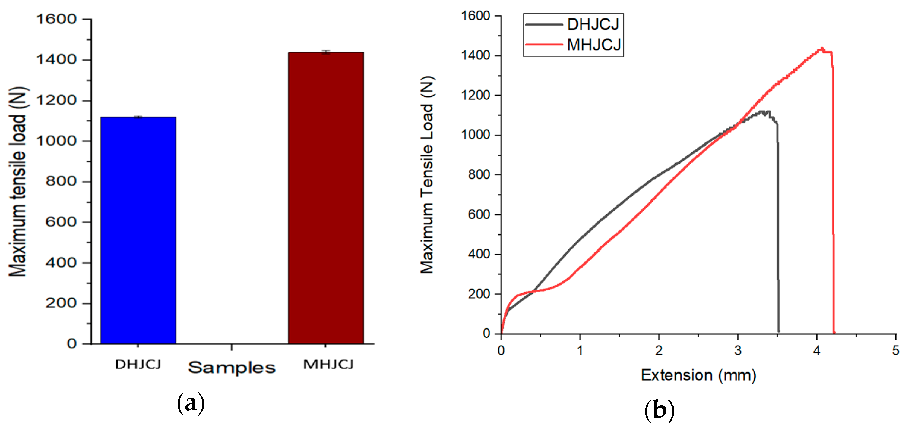
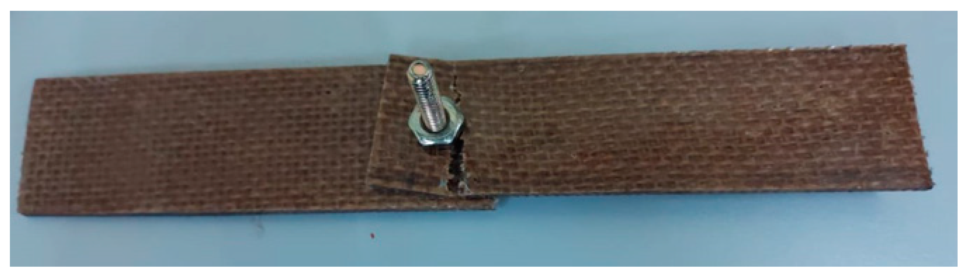
3.2. Lap Joint Testing

The MHJC and DHJC specimens were connected together in a lap joint configuration and put through their paces on a UTM machine so that the strength of the lap joint could be compared between the two types. For the purpose of this experiment, specimens with a hole diameter of 4 mm were chosen for both kinds of composites. Figure 5a depicts the maximum load that was recorded during tensile loading by lap joints of molded and drilled hole specimens, and Figure 5b displays their load-extension curves. Both types of specimens were subjected to tensile strength. When compared to DHJC specimens, it has been shown that MHJC specimens had a greater extension before breaking than the DHJC specimens. The extension for MHJC had an increase that was 14.67% more than expected. Following the completion of the tests, the fragmented 4MHJC specimen is shown in Figure 6.
It was determined that the MHJC joint specimens had a maximum tensile load of 1440 N, whereas the DHJC joint specimens had a maximum tensile load of 1120 N. When compared to the DHJC specimens, the MHJC specimens had a failure load that was 28.6% greater. As can be seen in Figure 7a,b, the fracture process was distinct between the DHJC and MHJC samples. After being subjected to tensile testing, the hole in the MHJC joints was not compromised in any way. The holes in the specimens that had been molded broke around the hole, but the hole in the DHJC sample was damaged during the testing process. Table 2 provides a comparison of molded and drilled holes and lists the results of the analysis in comparison to the present study.
Both a drilled hole with a force of 45 kN and a molded hole with a force of 60 kN showed that the carbon-fiber-based epoxy composites had the highest tensile strength of the two types of holes. The tensile strengths of the drilled hole and the molded hole, which were both made out of glass-fiber-based epoxy composites, were measured to be 19 kN and 35 kN, respectively. It was discovered that these values were lower than those observed in carbon-fiber-reinforced epoxy composites. The tensile strength of the composite materials consisting of aloe vera, banana fiber, and epoxy was 3 kN for drilled hole specimens and 3.3 kN for molded hole specimens when the holes were made via molding. When compared to the epoxy composites based on aloe vera and banana fiber, the tensile strength of the jute fiber/polyester composites was the worst among all of the tested materials. In our experiment, the results obtained from composites manufactured from jute fiber and epoxy were comparable to those obtained from composites built from aloe vera fiber, banana fiber, and epoxy-based materials. Natural-fiber-reinforced epoxy/polyester composites exhibited a tensile strength that was much lower than that of synthetic fiber composites.

4. Conclusions

An experimental study was conducted to analyze the tensile properties of drilled and molded NFRPCs with two distinct diameters: 4 mm and 8 mm. Moreover, the lap joint strength of specimens with 4 mm diameter molded/drilled holes was determined. The following conclusions can be drawn.
The molding technique yielded hole specimens of superior quality compared to those obtained by drilling. No instances of fractures, sharp edges, matrix breakage, or fiber pull-out were found in the molded hole specimens.
In the case of woven-fiber-reinforced polymer composites with molded holes, the presence of continuous fibers around the perimeter of the hole contributed to its structural integrity. Consequently, the hole remained undamaged throughout the testing process. Cracks were seen in regions of the specimens where a resin-rich area had developed as a result of fiber displacement.
In the case of DHJC specimens, it was observed that the fibers were discontinuous due to the shearing action during drilling. The process of drilling in composites gives rise to various defects that subsequently result in the premature failure of specimens under different loading environments.
The extension before failure was observed to be 16.44% and 46.15% higher for the 4MHJC and 8MHJC specimens, respectively, in comparison to the 4DHJC and 8DHJC specimens.
The lap joint test resulted in a maximum failure load of 1440 N for the joints with 4MHJC adherends and 1120 N for the joints with 4DHJC adherends. The occurrence of net tension failure was observed in both types of specimens.

Author Contributions

Conceptualization: J.K. and Y.S.; methodology: J.K.; validation: Y.S.; formal analysis: P.K.R.; writing—original draft preparation: J.K.; writing—review and editing: P.K.R.; supervision: I.S. and J.P.D. All authors have read and agreed to the published version of the manuscript.

Funding

Indian Council of Medical Research (Grant no. 2021-14663).

Data Availability Statement

No Data Available.

Acknowledgments

Authors greatly recognize the Design Innovation Center, IIT Roorkee, for providing the testing facilities.

Conflicts of Interest

The authors declare no conflict of interest.

References

  1. Al-Ameen, L.E.S.M.; Mustafa, A.L.M.N. Failure strength of fabric composites with drilled and molded-in holes. Al-Qadisiya J. Eng. Sci. 2011, 4, 1–8. [Google Scholar]
  2. Gurunathan, T.; Mohanty, S.; Nayak, S.K. A review of the recent developments in biocomposites based on natural fibers and their application perspectives. Compos. Part A Appl. Sci. Manuf. 2015, 77, 1–25. [Google Scholar] [CrossRef]
  3. Rakesh, P.K.; Singh, I.; Kumar, D. Compressive Behavior of Glass Fiber Reinforced Plastic Laminates with Drilled Hole. Adv. Mater. Res. 2012, 410, 349–352. [Google Scholar] [CrossRef]
  4. Jayabal, S.; Natarajan, U.; Sekar, U. Regression modeling and optimization of machinability behavior of glass-coir-polyester hybrid composite using factorial design methodology. Int. J. Adv. Manuf. Technol. 2011, 55, 263–273. [Google Scholar] [CrossRef]
  5. Rakesh, P.K.; Singh, I.; Kumar, D. Drilling of Composite Laminates with Solid and Hollow Drill Point Geometries. J. Compos. Mater. 2012, 46, 3173–3180. [Google Scholar] [CrossRef]
  6. Jayabal, S.; Velumani, S.; Navaneethakrishnan, P.; Palanikumar, K. Mechanical and machinability behaviors of woven coir fiber-reinforced polyester composite. Fibers Polym. 2013, 14, 1505–1514. [Google Scholar] [CrossRef]
  7. Yallew, T.B.; Kumar, P.; Singh, I. A study about hole making in woven jute fabric-reinforced polymer composites. Proc. Inst. Mech. Eng. Part L J. Mater. Des. Appl. 2015, 230, 888–898. [Google Scholar] [CrossRef]
  8. Nassar, M.M.A.; Arunachalam, R.; Alzebdeh, K.I. Machinability of natural fiber reinforced composites: A review. Int. J. Adv. Manuf. Technol. 2016, 88, 2985–3004. [Google Scholar] [CrossRef]
  9. Durão, L.M.P.; Gonçalves, D.J.; Tavares, J.M.R.; de Albuquerque, V.H.C.; Panzera, T.H.; Silva, L.J.; Vieira, A.A.; Baptista, A.P.M. Drilling delamination outcomes on glass and sisal reinforced plastics. Mater. Sci. Forum 2013, 730–732, 301–306. [Google Scholar] [CrossRef]
  10. Aravindh, S.; Umanath, K. Delamination in Drilling of Natural Fiber Reinforced Polymer Composites Produced by Compression Molding. Appl. Mech. Mater. 2015, 766–767, 796–800. [Google Scholar] [CrossRef]
  11. Balaji, N.S.; Jayabal, S.; Sundaram, S.K.; Rajamuneeswaran, S.; Suresh, P. Delamination analysis in drilling of Coir-polyester composites using design of experiments. Adv. Mater. Res. 2014, 984–985, 185–193. [Google Scholar] [CrossRef]
  12. Wan, M.; Li, S.E.; Yuan, H.; Zhang, W.H. Cutting force modelling in machining of fiber-reinforced polymer matrix composites (PMCs): A review. Compos. A Appl. Sci. 2019, 117, 34–55. [Google Scholar] [CrossRef]
  13. Venkateshwaran, N.; ElayaPerumal, A. Hole quality evaluation of natural fiber composite using image analysis technique. J. Reinf. Plast. Compos. 2012, 32, 1188–1197. [Google Scholar] [CrossRef]
  14. Singh, I.; Bhatnagar, N.; Viswanath, P. Drilling of uni-directional glass fiber reinforced plastics: Experimental and finite element study. Mater. Des. 2008, 29, 546–553. [Google Scholar] [CrossRef]
  15. Debnath, K.; Singh, I.; Dvivedi, A. Drilling characteristics of sisal fiber-reinforced epoxy and polypropylene composites. Mater. Manuf. Process. 2014, 29, 1401–1409. [Google Scholar] [CrossRef]
  16. Ashik, K.P.; Sharma, R.S. A Review on Mechanical Properties of Natural Fiber Reinforced Hybrid Polymer Composites. J. Miner. Mater. Charact. Eng. 2015, 3, 420–426. [Google Scholar] [CrossRef]
  17. Jauhari, N.; Mishra, R.; Thakur, H. Natural Fiber Reinforced Composite Laminates—A Review. Mater. Today Proc. 2015, 2, 2868–2877. [Google Scholar] [CrossRef]
  18. Lin, H.J.; Tsai, C.C.; Shie, J.S. Failure analysis of woven-fabric composites with molded-in holes. Compos. Sci. Technol. 1995, 55, 231–239. [Google Scholar] [CrossRef]
  19. Chang, L.W.; Yau, S.S.; Chou, T.W. Notched strength of woven fabric composites with molded-in holes. Composite 1987, 18, 233–241. [Google Scholar] [CrossRef]
  20. Yau, S.S.; Chou, T.W. Strength of woven-fabric composites with drilled and molded holes. ASTM Spec. Tech. Publ. 1988, 423–437. [Google Scholar] [CrossRef]
  21. Nejhad, M.N.; Chou Ghasemi, T.-W. Compression behaviour of woven carbon fiber-reinforced epoxy composites with molded-in and drilled holes. Composites 1990, 21, 33–40. [Google Scholar] [CrossRef]
  22. Langella, A.; Durante, M. Comparison of Tensile Strength of Composite Material Elements with Drilled and Molded-in Holes. Appl. Compos. Mater. 2008, 15, 227–239. [Google Scholar] [CrossRef]
  23. Parre, A.; Karthikeyan, B.; Balaji, A.; Udhayasankar, R. Investigation of chemical, thermal and morphological properties of untreated and NaOH treated banana fiber. Mater. Today Proc. 2020, 22, 347–352. [Google Scholar] [CrossRef]
  24. Rakesh, P.K.; Singh, I.; Kumar, D. Flexural Behavior of Glass Fiber Reinforced Plastic Laminates with Drilled Hole. Proc. Inst. Mech. Eng. Part L J. Mater. Des. Appl. 2012, 226, 149–158. [Google Scholar]
  25. Pickering, K.L.; Efendy MG, A.; Le, T.M. A review of recent developments in natural fiber composites and their mechanical performance. Compos. Part A Appl. Sci. Manuf. 2015, 83, 98–112. [Google Scholar] [CrossRef]
  26. Kumar, J.; Singh, I. Comparative Analysis of Molded and Drilled Holes in Jute Fiber Reinforced Plastic Laminates. J. Nat. Fibers 2021, 19, 7363–7373. [Google Scholar] [CrossRef]
  27. Singh, R.R.; Jayant, K.; Inderdeep, S.; Kumar, S.A. Comparative analysis of drilled and molded holes in short natural fiber reinforced composites. Proc. Inst. Mech. Eng. Part L J. Mater. Des. Appl. 2023, 14644207231191618. [Google Scholar] [CrossRef]
  28. Zitoune, R.; Crouzeix, L.; Collombet, F.; Tamine, T.; Grunevald, Y.-H. Behaviour of composite plates with drilled and molded hole under tensile load. Compos. Struct. 2011, 93, 2384–2391. [Google Scholar] [CrossRef]
Figure 1. (a) Lower half of mold (b) Upper half of mold (c) Composite laminate with molded holes.
Jcs 07 00376 g001
Figure 2. (a,b) 4MHJC1, (c) 8MHC1, (d) fractured MHJC 2 (e,f) 4DHJC3, (g) 8DHJC2 and (h) fractured DHJC3.
Jcs 07 00376 g002aJcs 07 00376 g002b
Figure 3. Maximum tensile load values recorded for different specimens.
Jcs 07 00376 g003
Figure 4. Load-extension curves for different specimens.
Jcs 07 00376 g004
Figure 5. (a) Maximum tensile failure load values recorded for lap joints with molded and drilled hole specimens; (b) Load-extension curves of lap joints with molded and drilled hole specimens.
Jcs 07 00376 g005
Figure 6. Fractured lap joint 4MHJC specimen.
Jcs 07 00376 g006
Figure 7. Fractured specimen after tensile testing; (a) Drilled hole, (b) Molded hole.
Jcs 07 00376 g007
Table 1. Nomenclature of specimens.
S. No.Specimen NameNomenclature
1.4 mm drilled hole jute composite4DHJC
2.4 mm molded hole jute composite4MHJC
3.8 mm drilled hole jute composite8DHJC
4.8 mm molded hole jute composite8MHJC
5.No hole jute compositeNHJC
6.4 mm drilled hole jute composite joint4DHJCJ
7.4 mm molded hole jute composite joint4MHJCJ
Table 2. A comparative analysis of molded and drilled holes in fiber-reinforced composites.
No.MaterialsPropertiesReferences
1.Jute fiber/epoxy compositesMaximum tensile load
(a) Drilled hole specimens = 2.1 kN
(b) Molded hole specimens = 3.2 kN
Present study
2.Jute fiber/Polyester compositesMaximum tensile load
(a) Drilled hole specimens = 1.9 kN
(b) Molded hole specimens = 2.2 kN
[26]
3.Aloe vera/banana fiber/epoxy compositesMaximum tensile load
(a) Drilled hole specimens = 3 kN
(b) Molded hole specimens = 3.3 kN
[27]
4.Carbon fiber/epoxy compositesMaximum tensile load
(a) Drilled hole specimens = 45 kN
(b) Molded hole specimens = 60kN
[28]
5.Glass fiber/epoxy compositesMaximum tensile stress
(a) Drilled hole specimens = 225 MPa
(b) Molded hole specimens = 300 MPa
[22]
6.Glass fiber/epoxy compositesMaximum tensile load
(a) Drilled hole specimens = 19 kN
(b) Molded hole specimens = 35 kN
[18]
7.Glass fiber/Polyester compositesMaximum tensile stress
(a) Drilled hole specimen = 253.2 MPa
(b) Molded hole specimen = 271 MPa
[1]
8.Graphite/epoxy composites
[45°/0°]
Maximum tensile stress
(a) Drilled hole specimen = 395 MPa
(b) Molded hole specimen = 463 MPa
[19]
Disclaimer/Publisher’s Note: The statements, opinions and data contained in all publications are solely those of the individual author(s) and contributor(s) and not of MDPI and/or the editor(s). MDPI and/or the editor(s) disclaim responsibility for any injury to people or property resulting from any ideas, methods, instructions or products referred to in the content.

