Article

Medium-Temperature Glass-Composite Phosphate Materials for the Immobilization of Chloride Radioactive Waste

by
Anna V. Frolova
*,
Ksenia Y. Belova
and
Sergey E. Vinokurov
*
Vernadsky Institute of Geochemistry and Analytical Chemistry of Russian Academy of Sciences, 19 Kosygin St., 119991 Moscow, Russia
*
Authors to whom correspondence should be addressed.
J. Compos. Sci. 2023, 7(9), 363; https://doi.org/10.3390/jcs7090363
Submission received: 7 August 2023 / Revised: 18 August 2023 / Accepted: 29 August 2023 / Published: 1 September 2023
(This article belongs to the Section Composites Applications)

Abstract

:
Among the many radiochemical problems, the search for new materials and technologies for the immobilization of radioactive waste remains relevant, and the range continues to change and expand. The possibility of immobilizing the spent chloride electrolyte after the pyrochemical processing of the mixed uranium-plutonium spent nuclear fuel of the new fast reactor BREST-OD-300 on lead coolant into glass-composite phosphate materials synthesized at temperatures of 650–750 °C was studied. The structure of the obtained samples was studied using XRD and SEM/EDS methods. It has been shown that the spent electrolyte simulator components create stable mixed pyrophosphate phases in the glass composite structure. The materials were found to have high hydrolytic stability. This indicates the promise of using phosphate glass composites as materials for the reliable immobilization of the spent electrolyte.

1. Introduction

One of the priority tasks of the nuclear power industry is to address the issues of handling radioactive waste (RW) generated at all stages of the nuclear fuel cycle (NFC). The greatest danger among these wastes is high-level waste (HLW) generated during the reprocessing of spent nuclear fuel (SNF). SNF contains various actinides, fission products, and elements of fuel assemblies [1].
There are different approaches to SNF and HLW management. In some countries, in particular in the USA, SNF from power reactors cannot be reprocessed, while in other countries, such as France and Russia, it is planned to extract actinides and fractionate waste both for the secondary use of residual valuable components, and for more economically justified waste storage and disposal methods [1,2,3]. When fractionating SNF, various final compositions of HLW are possible, and the vitrification process for their reliable isolation was proposed back in the 1950s [4]. In the generally accepted multi-barrier approach to HLW management, the insulating matrix, glass in particular, is the first and main barrier designed to reliably retain radionuclides. As for the next protection barriers, it is proposed to use various buffer clay materials and natural enclosing underground rocks at the site of the proposed deep disposal of HLW [5]. Currently, aluminophosphate and borosilicate glasses are used in industry to incorporate HAW [6]; however, the process of searching for both glass-like and other forms for RW immobilization continues.
In the 1970s, active research into ceramic materials for HLW immobilization began when the Synroc titanate ceramic was proposed in Australia [7,8,9]. The theoretical basis for considering ceramics as matrices for HLW immobilization was the ability of some ceramic materials containing natural radionuclides to maintain their stability for hundreds of thousands of years [10]. Glass ceramics and glass-composite materials [11,12,13,14], obtained via the slow cooling of glass [15] or using other methods, such as uniaxial pressing, hot isostatic pressing, liquid-phase sintering, and the sintering of viscous composites, are also promising matrices [16]. In such matrices, it is usually best to try to combine the properties of glasses as advantageously as possible, for example, their relative versatility, and properties of ceramics, in particular, the initial target crystallinity. It is known that glasses can have a tendency to crystallize during synthesis or after a period of time [17], which is an undesirable process due to the spontaneous formation of phases that may not include the components of immobilized HLW.
At the same time, some waste components are problematic for immobilization in high-temperature glass matrices and ceramics. In particular, some such components are relatively volatile cesium radionuclides (134,135,137Cs) [18]. Also, vitrification is recognized as ineffective for the immobilization of chloride wastes, which are formed during the pyrochemical processing of SNF [19]. Such wastes are generated in the USA after the pyrochemical processing of SNF from the research reactor EBR-II [20]. In Russia, chloride waste is generated during the processing of mixed uranium-plutonium SNF (SNUP SNF) in the BREST-OD-300 reactor with lead coolant [21].
In some works [21,22,23], it has been shown that matrices of the “zeolite/sodalite in glass” type can be used for this type of waste. The sintering of chlorapatite and borosilicate glass [24] and the sintering of glass powders to obtain glass-composite materials [24,25,26] were also proposed, since it is known that glass composite materials have lower synthesis temperatures as well as the possibility of forming target stable phases. It was also proposed to sinter clinoptilolite, imitating spent sorbent, with borosilicate glass [27]. What is interesting in this approach is that mobile 137Cs can be retained in the matrix both due to the crystalline phases of borosilicate glass formed during the synthesis of the glass-composite material, and due to the structure of the clinoptilolite-sorbent itself, which is a waste material. This made it possible to increase the loading of wastes to 73 wt%, which in the long term significantly reduces the volume of encapsulated wastes in comparison with cement and some ceramics and also qualitatively includes relatively easily volatile Cs in the structure of the material, in contrast to high-temperature glasses and ceramics.
We considered iron phosphate glass [28], the synthesis temperature of which is lower than that of aluminophosphate and borosilicate glasses, as well as a magnesium–potassium phosphate matrix [29,30] obtained at room temperature as promising for chloride wastes. The technology for obtaining glass composite materials of various synthesis temperatures in the range of 450–750 °C was also tested based on known glass compositions [31]. It is assumed that the absence of changes in the synthesis of glasses, which are a precursor for the production of glass composites, can make the industrial technology fairly easy to implement. It was shown that the synthesis of such glass composite materials is possible at a temperature of 550 °C, while the optimal performance was observed for samples of a simple composition, mol%: 60 P2O5 -40 Fe2O3, synthesized at 650–750 °C.
The purpose of this work was to study the possibility of synthesizing glass composite materials at temperatures of 650–750 °C as well as to study the properties of the obtained materials when a spent electrolyte simulator is switched on after the pyrochemical processing of spent fuel from the BREST-OD-300 reactor.

2. Materials and Methods

2.1. Chemicals and Procedures

As a precursor for the glass-composite material, glass of the composition was used, mol%: 40 Fe2O3-60 P2O5 (FP glass), which is a well-known simple and stable composition of iron phosphate glasses [32]. Previously, we showed [31] that this glass is capable of forming ortho- and pyrophosphate ceramic phases during the synthesis of glass-composite materials at temperatures of 550–750 °C, and the formation of these phases depends on the synthesis temperature. So, predominantly orthophosphate compositions were obtained at a synthesis temperature of 550 °C, and pyrophosphate compositions at temperatures of 650–750 °C.

Synthesis of the Medium-Temperature Glass-Composite Phosphate Materials

The synthesis of glass-composite phosphate materials included 2 stages. At the first stage, FP glass was obtained from a mixture consisting of dry salts (NH4)2HPO4 (GOST 3772-74) and Fe2O3 (TU 6-09-5346-87) (Len-reactive, Saint Petersburg, Russia) by heating in quartz crucibles to 450 °C in a laboratory furnace SNOL 30/1300 (AB UMEGA GROUP, Utena, Lithuania) to remove water and ammonia from ammonium dihydrogen phosphate, and further heating to 1110 °C followed by holding for 1 h. The melt was poured onto a dense metal tray for rapid cooling in air.
The second stage consisted of the following. The resulting glass samples were crushed to a fraction of less than 0.07 mm, then a mixture of chlorides was added to the obtained powders as a simulator of the spent electrolyte of the composition Li0.4K0.28La0.08Cs0.016Sr0.016Ba0.016Cl (25.7 wt% LiCl + 31.6% KCl + 4.1 wt% CsCl + 5.1 wt% BaCl2 + 3.8 wt% SrCl2 + 29.7 wt% LaCl3) in an amount of 10 wt%. The resulting mixture was thoroughly mixed, then weighed portions were taken from the resulting mixture, which were pressed into tablets about 10 mm in diameter and about 35 mm thick under a pressure of 5 MPa using a PGR-10 laboratory hydraulic press (LabTools, Saint Petersburg, Russia). The pellets obtained were sintered at temperatures of 650, 700 and 750 °C for 6 h in a muffle furnace SNOL 30/1300 (AB UMEGA GROUP, Utena, Lithuania) on a stainless steel substrate (for specimens synthesized at 650 °C) and corundum substrate (for samples synthesized at temperatures of 700 and 750 °C). The calculated elemental composition of the obtained samples is shown in Table 1.

2.2. Methods

The phase composition of glass-composite phosphate material samples was determined using X-ray diffraction (XRD) on an MiniFlex 600 X-ray diffractometer (Rigaku, Tokyo, Japan). XRD data were interpreted using the Smartlab Studio II software package (Rigaku, Tokyo, Japan) with a PDF-2 powder database. The microstructure of the samples was studied using scanning electron microscopy (SEM) on a Mira3 microscope (Tescan, Brno, Czech Republic) with a field emission cathode at an accelerating voltage of 30 kV in the secondary electron detection mode. The samples were attached to the holder using conductive carbon tape. To ensure charge drain from the samples, their surface was covered with a layer of carbon (10 nm thick) via thermal pulsed evaporation on a Q150R ES setup (Quorum Technologies, Lewes, UK). Electron probe microanalysis of the samples was performed by energy dispersive X-ray spectroscopy (EDS) using an X-Max analyzer (Oxford Inst., High Wycombe, UK).
The hydrolytic stability of the obtained samples was determined in accordance with the static PCT method [33]. To do this, the samples were crushed to a fraction of 0.01–0.02 mm, and a mass of 1 g was taken. The resulting powders were washed with bidistilled water and alcohol before testing to exclude the possibility of dust fraction ingress. The powders were placed in a plastic container filled with 10 mL of bidistilled water, and thermostated at a temperature of 90 ± 2 °C in a SCHS-80-01 laboratory oven (SKTB SPU, Smolensk, Russia) for 7 days. The solutions were decanted after leaching and centrifuged for 5 min at 8000 rpm in a CLn-16 centrifuge (Changhsa Xiangzhi Centrifuge Instrument, Changsha, China). The content of the components in the solution after leaching was determined using ICP-AES (iCAP-6500 Duo (Thermo Scientific, Waltham, MA, USA)).
The leaching rate, LR, [g/(cm2·day)] of the components was calculated using the following equation:
LR = c   · V S   · f   · t   ,
where c—element concentration in solution after leaching, g/L; V—the volume of leaching agent, L; S—the sample surface, cm2; f—element content in matrix, g/g; and t—duration of the leaching period.

3. Results and Discussion

3.1. Geometric Parameters and the Density of Glass-Composite Phosphate Materials

The appearance of the obtained samples is shown in Figure 1. The glass-composite material sample synthesized at 650 °C is visually highly inhomogeneous. This is probably due to the redox processes occurring during sintering on a metal substrate. Inclusions were observed only on the surface of the sample and were represented by a thin film of predominantly ferruginous composition. For this reason, samples synthesized at 700 and 750 °C were sintered on a corundum substrate. All glass-composite materials sintered at different temperatures visually formed dense pellets. The highest visual homogeneity was characteristic of the sample synthesized at 750 °C.
The geometric parameters of the tablet samples before and after sintering, as well as the density of the samples obtained, are presented in Table 2. The samples were measured with a caliper, and the measurement error was ±0.05 mm. It should be noted that an increase in density during the synthesis of glass-composite materials for the purpose of RW immobilization is a desirable parameter. In order to improve the safety of waste management, the reduction in the volume of RW and high strength of the material are significant criteria when choosing forms of immobilization of RW. With an increase in the synthesis temperature, a tendency of the density of the obtained glass composite materials to increase is visible. At the same time, a further increase in the synthesis temperature in this case does not seem appropriate due to the need for the maximum inclusion of volatile waste components.

3.2. Study of the Composition and Structure of Glass-Composite Phosphate Materials

3.2.1. Characterization of the Synthesized Glass-Composite Phosphate Materials by X-ray Diffraction

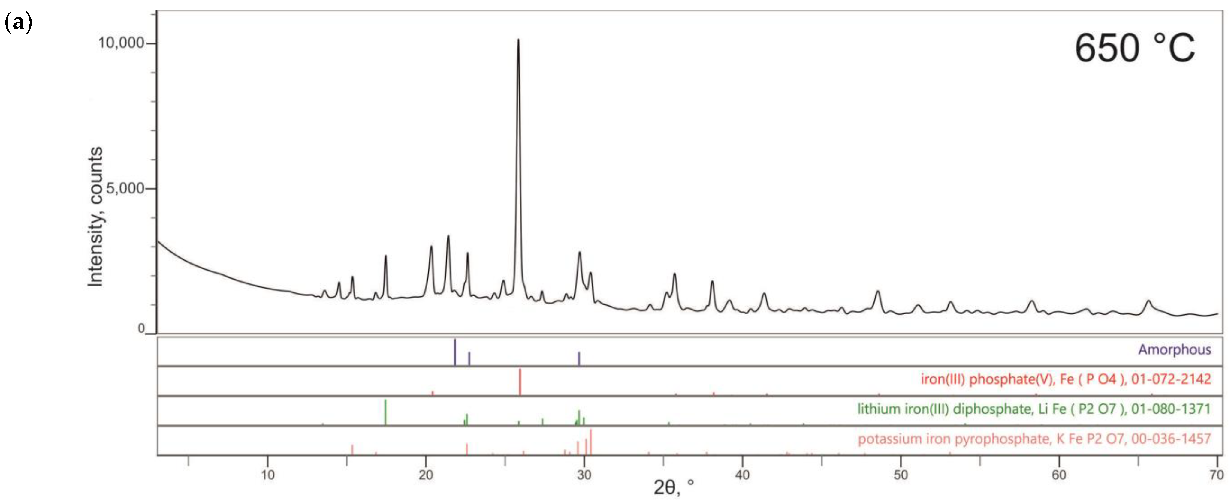
The diffraction patterns of the obtained samples are shown in Figure 2. The sample synthesized at 650 °C (Figure 2a) was formed by a minor residual amorphous phase and iron orthophosphate, while the components of the added waste simulants formed mixed pyrophosphate phases of lithium iron diphosphate and potassium iron diphosphate. The samples synthesized at 700 and 750 °C (Figure 2b,c) were completely crystallized and consisted of basic ortho- and pyrophosphate phases. It is not possible to achieve a completely pyrophosphate structure, as was the case in samples without the addition of a spent electrolyte simulant, obtained at these temperatures [31], although a tendency towards a decrease in iron orthophosphate was observed. In this case, the imitator components were also included in the mixed pyrophosphate phases of lithium-iron diphosphate and potassium-iron diphosphate, as in the case of the sample synthesized at 650 °C. It is not possible to detect phases containing other components of the spent electrolyte simulator using this method, probably due to the insufficient limit of detection of crystalline phases.

3.2.2. Characterization of the Synthesized Glass-Composite Phosphate Materials by SEM

The SEM micrographs of the surface of the glass-composite materials obtained at 650, 700, and 750 °C are shown in Figure 3, and the data of the elemental composition of the phases according to the EMF data are given in Table 3. The basis of the surface samples in all three cases is a similar crystalline macrophase with a uniform distribution of components in it, which is characterized by a slightly higher iron content (Table 3, Phase #1) than in the calculated composition (Table 1). At the same time, in the sample synthesized at 650 °C, there is a microphase of excellent composition (Phase #2, Figure 3a), and in the samples synthesized at 700 and 750 °C, the presence of a significant phase of inhomogeneous composition is observed on the surface (Phase #3, Figure 3b,c).
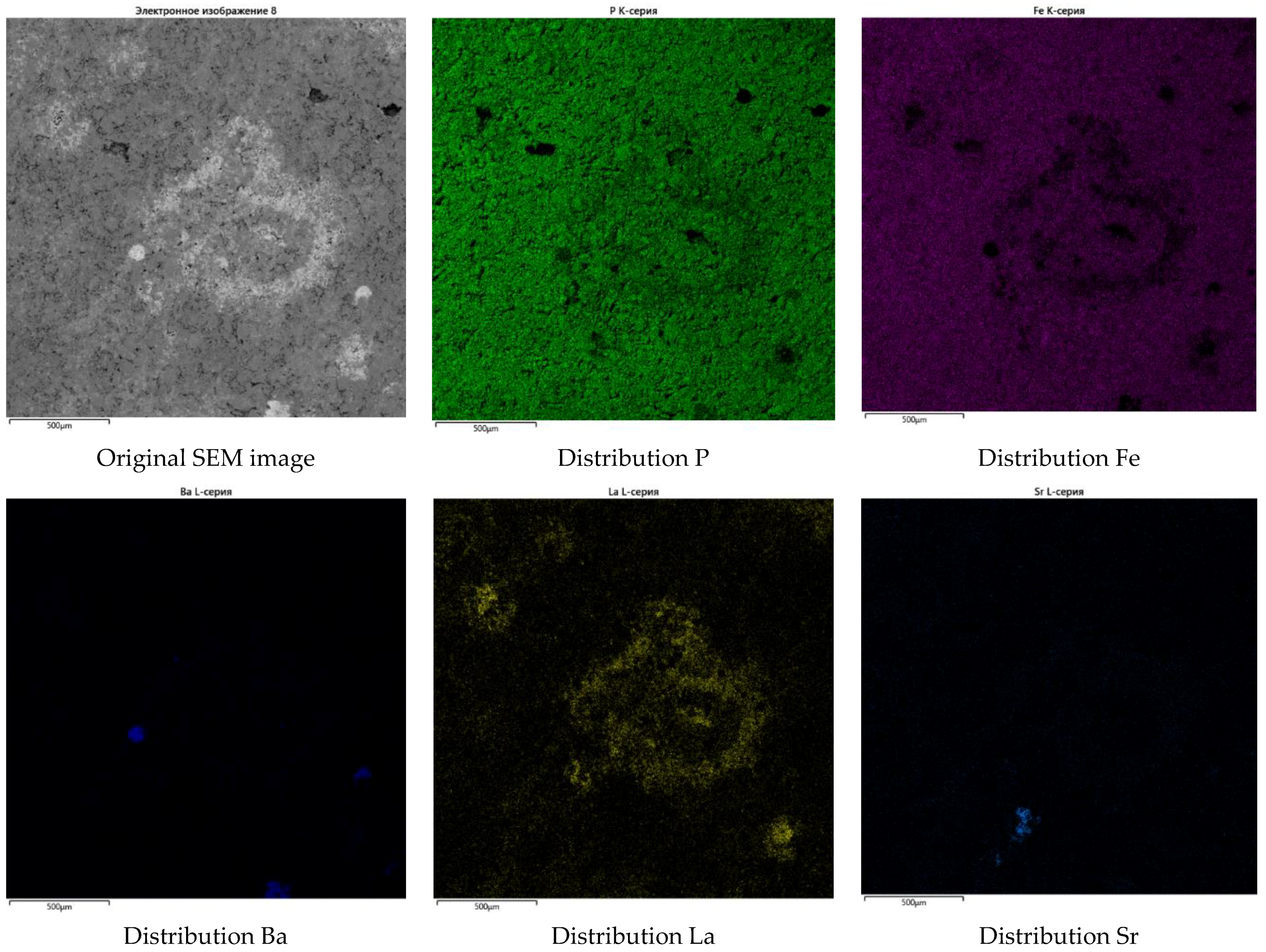
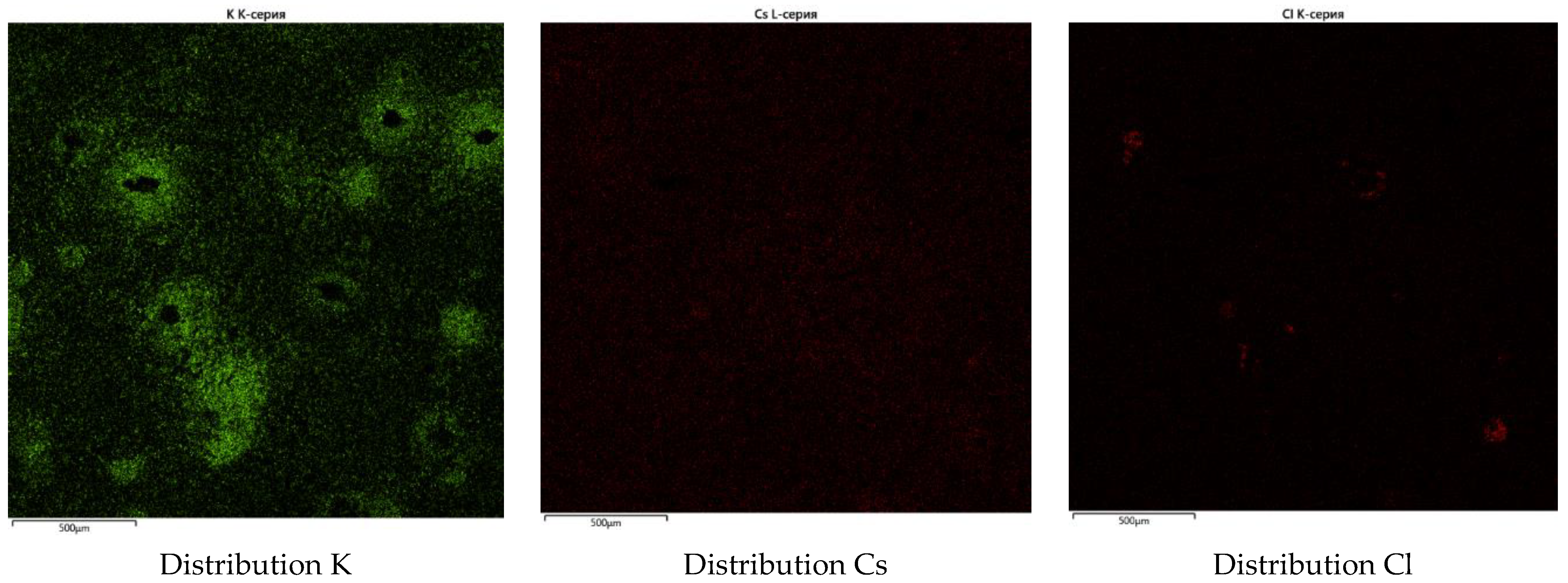
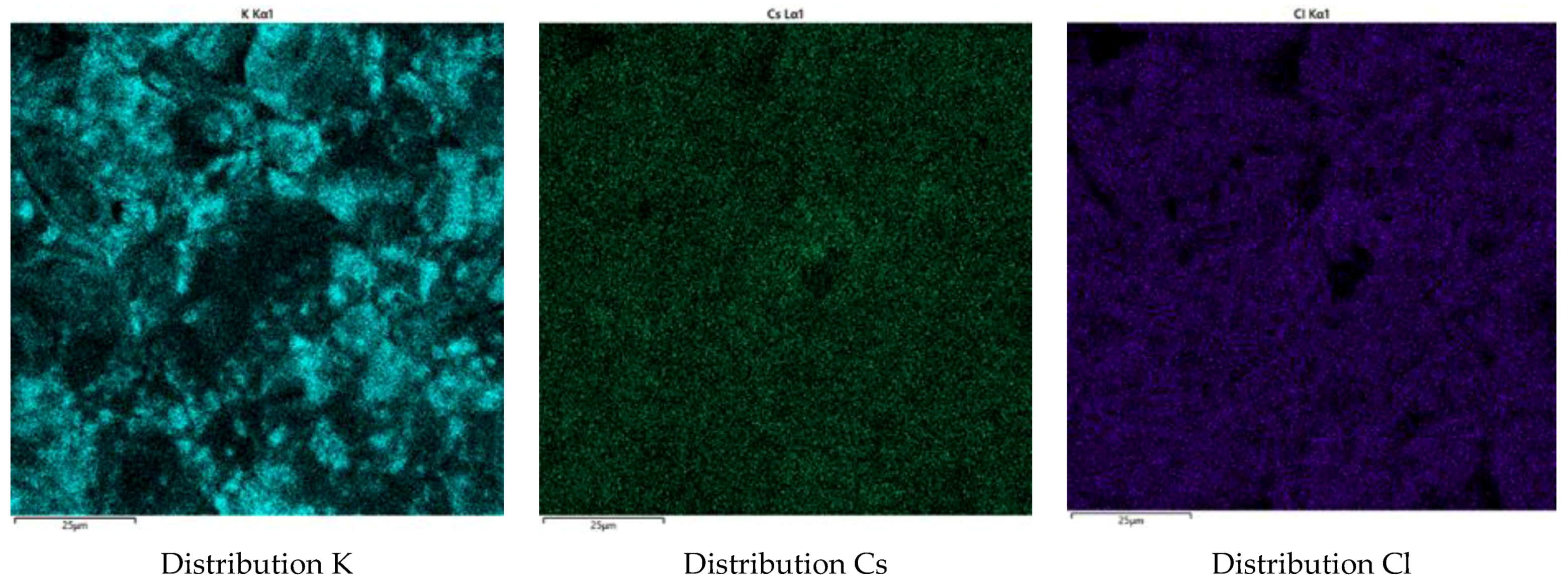
Due to the uneven distribution of components in phase 3 (Phase #3, Figure 3b,c) of the samples synthesized at 700 and 750 °C, instead of the composition of this phase, elemental maps of the distribution of components in the samples synthesized at 700 and 750 °C were constructed (Figure 4 and Figure 5). It can be seen that synthesis at these temperatures leads to the formation of mixed phases on the sample surface, consisting of components of added spent electrolyte simulators. In this case, La and Ba, apparently, can replace Fe in the surface phosphate structures of the glass-composite material of the given composition. This is probably the reason for the higher content of Fe in the main macrophase (Table 3, Phase #1) compared to the calculated composition in these samples, which ultimately leads to the formation of higher iron pyrophosphate phases. At the same time, the composition of the surface of the main macrophase of the sample synthesized at 650 °C is similar, within the error, to the composition of the main phase in the samples synthesized at 700 and 750 °C, but iron pyrophosphate was not detected by XRD (Figure 2a). It can be interpreted in a way where the pyrophosphate phase in this sample could be insignificant and formed only on the surface, while the main phase in the bulk of the sample is represented by iron orthophosphate. It seems curious that in the sample synthesized at 650 °C, in contrast to the samples synthesized at 700 and 750 °C, phases that formed mixed phosphates with components of the RW simulator could not be detected on the surface. At the same time, these phases are detected by the XRD. This may be due to both the synthesis temperature and the synthesis on a metal substrate. In this case, non-target processes of interaction with the substrate material occurred on the sample surface, which ultimately led to the formation of large high-iron inclusions on it (Figure 1), and this could prevent the formation of phosphate phases containing spent electrolyte simulator components. In view of the fact that synthesis at 650 °C leads to the formation of a predominantly orthophosphate ferrous phase, and also due to the retention of an insignificant amorphous glass phase and a lower density of the sample compared to samples obtained at 700 and 750 °C, synthesis on an amorphous corundum substrate at 650 °C was not carried out.
As can be seen from Figure 4 and Figure 5, the samples synthesized at 700 and 750 °C show an almost uniform distribution of P, Fe, Cs, and Cl on the surface of the sample. Based on this, it can be assumed that there is a common macrophase on the surface of the glass-composite materials synthesized at 700 and 750 °C, which was not determined by XRD and EDS due to the initially low concentrations of Cs and Cl in the composition of the FP matrix with the spent electrolyte simulator.

3.3. Hydrolytic Resistance of Glass-Composite Phosphate Materials

Figure 6 shows the results of the leaching of the structure-forming components of the glass-composite material and the components of the added spent electrolyte simulant. It is noted that there is no clear dependence of the leaching rate on the temperature of sample synthesis. So, for P, a decrease in the leaching rate is noted with an increase in the synthesis temperature from 5.2 × 10⁻⁷ g/(cm2∙day) for a sample synthesized at 650 °C to 8.4 × 10⁻⁸ g/(cm2∙day) for a sample synthesized at 750 °C. For Fe, the opposite is typical. The leaching rate increases from 5.8 × 10⁻¹⁰ g/(cm2∙day) to 2.7 × 10⁻⁸ g/(cm2∙day) as the temperature rises to 750 °C. At the same time, the lowest leaching rate for Fe is observed in the sample synthesized at 700 °C and is 1.3 × 10⁻¹⁰ g/(cm2∙day). In this case, the sample synthesized at 700 °C is characterized by an increase in the leaching rate for La and Li. For a glass-composite material obtained by sintering borosilicate glass and clinoptilolite by a similar method, the cesium leaching rate in a similar test, but at 40 °C, is on the order of 10−7–10−6 g/(cm2∙day) [27]. At the same time, the values of leaching rates for phosphate glasses and ceramics, promising for the immobilization of HLW and having a similar anionic structure with a phosphate glass composite material, in the PCT test at a temperature of 90 °C, could have values of the order of 10−5–10−4 g/(cm2∙day) for structure-forming components [34] and lower values for components of waste simulators [35]. Therefore, the obtained values for a glass-composite material synthesized at temperatures of 650–750 °C can be considered acceptable.

4. Conclusions

It has been established that at synthesis temperatures of 650–750 °C, glass-composite phosphate materials consist of phases of mixed pyrophosphates, including components of the immobilized spent electrolyte. In this case, synthesis at 650 °C leads to the retention of a residual non-target amorphous phase, which completely disappears when the synthesis temperature is increased to 700 °C. Increasing the synthesis temperature also promotes the formation of pyrophosphate phases, which include waste components. All samples synthesized at 650–750 °C have high hydrolytic stability. Thus, the leaching rates of structure-forming components, according to the results of the PCT standard, are at the level of 10−10–10−7 g/(cm2∙day), and the spent electrolyte simulator components are at 10−10–10−4 g/(cm2∙day). It follows that the optimal temperatures for the synthesis of materials are 700–750 °C, which makes it possible to completely get rid of the non-target glass phase. A further increase in the synthesis temperature seems unreasonable due to the presence of volatile waste components such as Cs in the spent electrolyte. Thus, it has been shown that glass-composite phosphate materials are a promising industrial compound for the immobilization of spent chloride electrolyte. It should be especially noted that the crystalline matrix, which is characterized by the necessary stability, is obtained at temperatures that are at least 5–6 hundreds of degrees lower than known ceramics such as Synroc. At the same time, such a radical decrease in the synthesis temperature significantly reduces the requirements for industrial equipment for the solidification of radioactive waste, as well as for the conditions for decommissioning such equipment.

Author Contributions

Conceptualization, A.V.F.; methodology, A.V.F. and S.E.V.; validation, A.V.F.; formal analysis, A.V.F. and K.Y.B.; investigation, A.V.F. and K.Y.B.; resources, S.E.V.; writing—original draft preparation, A.V.F.; writing—review and editing, S.E.V.; visualization, A.V.F. and S.E.V.; supervision, S.E.V.; project administration, S.E.V.; funding acquisition, S.E.V. All authors have read and agreed to the published version of the manuscript.

Funding

The work was supported by the Russian Science Foundation (project No. 22-29-01523); https://rscf.ru/en/project/22-29-01523/, (accessed on 27 August 2023).

Data Availability Statement

Not applicable.

Acknowledgments

The authors thank I.N. Gromyak (Laboratory of Methods for Investigation and Analysis of Substances and Materials, GEOKHI RAS) for performing the ICP-AES analysis, and K.A. Lorenz (Meteoritics laboratory, GEOKHI RAS) for the analysis of samples via SEM with EDS.

Conflicts of Interest

The authors declare no conflict of interest. The funders had no role in the design of the study; in the collection, analyses, or interpretation of data; in the writing of the manuscript, or in the decision to publish the results.

References

  1. Fedorov, Y.S.; Zil’berman, B.Y.; Aloi, A.S.; Puzikov, E.A.; Shadrin, A.Y.; Alyapyshev, M.Y. Problems of Modernization of Spent Nuclear Fuel Extraction Processing. Russ. J. Gen. Chem. 2011, 81, 1932–1948. [Google Scholar] [CrossRef]
  2. Lee, H. Oxide Electroreduction and Other Processes for Pyrochemical Processing of Spent Nuclear Fuels. In Reprocessing and Recycling of Spent Nuclear Fuel; Elsevier: Amsterdam, The Netherlands, 2015; pp. 415–436. [Google Scholar]
  3. Alyapyshev, M.Y.; Babain, V.A.; Ustynyuk, Y.A. Recovery of Minor Actinides from High-Level Wastes: Modern Trends. Russ. Chem. Rev. 2016, 85, 943–961. [Google Scholar] [CrossRef]
  4. Watson, L.C.; Aikin, A.M.; Bancroft, A.I. The Permanent Disposal of Highly Radioactive Wastes by Incorporation into Glass. In Proceedings of the Scientific Conference on the Disposal of Radioactive Wastes; International Atomic Energy Agency (IAEA), Vienna, Austria, 16–21 November 1959. [Google Scholar]
  5. Vuori, S. The Environmental and Ethical Basis of the Geological Disposal of Long-Lived Radioactive Waste. ATS Ydintekniikka 1995, 24, 16–17. [Google Scholar]
  6. Ma, B.; Charlet, L.; Fernandez-Martinez, A.; Kang, M.; Madé, B. A Review of the Retention Mechanisms of Redox-Sensitive Radionuclides in Multi-Barrier Systems. Appl. Geochem. 2019, 100, 414–431. [Google Scholar] [CrossRef]
  7. Gregg, D.J.; Farzana, R.; Dayal, P.; Holmes, R.; Triani, G. Synroc Technology: Perspectives and Current Status (Review). J. Am. Ceram. Soc. 2020, 103, 5424–5441. [Google Scholar] [CrossRef]
  8. Vance, E.R.; Chavara, D.T.; Gregg, D.J. Synroc Development—Past and Present Applications. MRS Energy Sustain. 2017, 4, 8. [Google Scholar] [CrossRef]
  9. Deokattey, S.; Bhaskar, N.; Kalyane, V.L.; Kumar, V.; Jahagirdar, P.B. Borosilicate Glass and Synroc R&D for Radioactive Waste Immobilization: An International Perspective. JOM 2003, 55, 48–51. [Google Scholar] [CrossRef]
  10. Ringwood, E.; Kelly, P.M. Immobilization of High-Level Waste in Ceramic Waste Forms. Philos. Trans. R. Soc. Lond. Ser. A Math. Phys. Sci. 1986, 319, 63–82. [Google Scholar] [CrossRef]
  11. Zhang, Y.; Vance, E.R. Plutonium in Monazite and Brabantite: Diffuse Reflectance Spectroscopy Study. J. Nucl. Mater. 2008, 375, 311–314. [Google Scholar] [CrossRef]
  12. Arinicheva, Y.; Bukaemskiy, A.; Neumeier, S.; Modolo, G.; Bosbach, D. Studies on Thermal and Mechanical Properties of Monazite-Type Ceramics for the Conditioning of Minor Actinides. Prog. Nucl. Energy 2014, 72, 144–148. [Google Scholar] [CrossRef]
  13. Crum, J.; Maio, V.; McCloy, J.; Scott, C.; Riley, B.; Benefiel, B.; Vienna, J.; Archibald, K.; Rodriguez, C.; Rutledge, V.; et al. Cold Crucible Induction Melter Studies for Making Glass Ceramic Waste Forms: A Feasibility Assessment. J. Nucl. Mater. 2014, 444, 481–492. [Google Scholar] [CrossRef]
  14. McCloy, J.S.; Schuller, S. Vitrification of Wastes: From Unwanted to Controlled Crystallization, a Review. Comptes Rendus Géosci. 2022, 354, 121–160. [Google Scholar] [CrossRef]
  15. Li, H.; Wu, L.; Wang, X.; Xu, D.; Teng, Y.; Li, Y. Crystallization Behavior and Microstructure of Barium Borosilicate Glass–Ceramics. Ceram. Int. 2015, 41, 15202–15207. [Google Scholar] [CrossRef]
  16. Richerson, D.W.; Lee, W.E. Modern Ceramic Engineering; CRC Press: Boca Raton, FL, USA, 2018; ISBN 9780429488245. [Google Scholar]
  17. Jantzen, C.M.; Lee, W.E.; Ojovan, M.I. Radioactive Waste (RAW) Conditioning, Immobilization, and Encapsulation Processes and Technologies: Overview and Advances. In Radioactive Waste Management and Contaminated Site Clean-Up; Elsevier: Amsterdam, The Netherlands, 2013; pp. 171–272. [Google Scholar]
  18. Wu, J.; Zhou, K.; Dai, M. Impacts of the Fukushima Nuclear Accident on the China Seas: Evaluation Based on Anthropogenic Radionuclide 137Cs. Chin. Sci. Bull. 2013, 58, 552–558. [Google Scholar] [CrossRef]
  19. Donald, I.W.; Metcalfe, B.L.; Fong, S.K.; Gerrard, L.A.; Strachan, D.M.; Scheele, R.D. A Glass-Encapsulated Calcium Phosphate Wasteform for the Immobilization of Actinide-, Fluoride-, and Chloride-Containing Radioactive Wastes from the Pyrochemical Reprocessing of Plutonium Metal. J. Nucl. Mater. 2007, 361, 78–93. [Google Scholar] [CrossRef]
  20. Simpson, M.F.; Sachdev, P. Development of electrorefiner waste salt disposal process for the EBR- II spent fuel treatment project. Nucl. Eng. Technol. 2008, 40, 175–182. [Google Scholar] [CrossRef]
  21. Shadrin, A.Y.; Dvoeglazov, K.N.; Maslennikov, A.G.; Kashcheev, V.A.; Tret’yakova, S.G.; Shmidt, O.V.; Vidanov, V.L.; Ustinov, O.A.; Volk, V.I.; Veselov, S.N.; et al. PH Process as a Technology for Reprocessing Mixed Uranium–Plutonium Fuel from BREST-OD-300 Reactor. Radiochemistry 2016, 58, 271–279. [Google Scholar] [CrossRef]
  22. Pereira, C.; Hash, M.; Lewis, M.; Richmann, M. Ceramic-Composite Waste Forms from the Electrometallurgical Treatment of Spent Nuclear Fuel. JOM 1997, 49, 34–40. [Google Scholar] [CrossRef]
  23. Priebe, S.; Bateman, K. The Ceramic Waste Form Process at Idaho National Laboratory. Nucl. Technol. 2008, 162, 199–207. [Google Scholar] [CrossRef]
  24. Jena, H.; Maji, B.K.; Asuvathraman, R.; Govindan Kutty, K.V. Synthesis and Thermal Characterization of Glass Bonded Ca-Chloroapatite Matrices for Pyrochemical Chloride Waste Immobilization. J. Non-Cryst. Solids 2012, 358, 1681–1686. [Google Scholar] [CrossRef]
  25. Michie, E.M.; Grimes, R.W.; Boccaccini, A.R. Hot-Pressed Phosphate Glass–Ceramic Matrix Composites Containing Calcium Phosphate Particles for Nuclear Waste Encapsulation. J. Mater. Sci. 2008, 43, 4152–4156. [Google Scholar] [CrossRef]
  26. Stoch, P.; Ciecinska, M. Thermochemistry of Phosphate Glasses for Immobilization of Dangerous Waste. J. Therm. Anal. Calorim. 2012, 108, 705–709. [Google Scholar] [CrossRef]
  27. Juoi, J.M.; Ojovan, M.I.; Lee, W.E. Microstructure and Leaching Durability of Glass Composite Wasteforms for Spent Clinoptilolite Immobilisation. J. Nucl. Mater. 2008, 372, 358–366. [Google Scholar] [CrossRef]
  28. Danilov, S.S.; Frolova, A.V.; Kulikova, S.A.; Vinokurov, S.E.; Maslakov, K.I.; Teterin, A.Y.; Teterin, Y.A.; Myasoedov, B.F. Immobilization of Rhenium as a Technetium Surrogate in Aluminum Iron Phosphate Glass. Radiochemistry 2021, 63, 99–106. [Google Scholar] [CrossRef]
  29. Kulikova, S.A.; Belova, K.Y.; Tyupina, E.A.; Vinokurov, S.E. Conditioning of Spent Electrolyte Surrogate LiCl-KCl-CsCl Using Magnesium Potassium Phosphate Compound. Energies 2020, 13, 1963. [Google Scholar] [CrossRef]
  30. Kulikova, S.A.; Danilov, S.S.; Matveenko, A.V.; Frolova, A.V.; Belova, K.Y.; Petrov, V.G.; Vinokurov, S.E.; Myasoedov, B.F. Perspective Compounds for Immobilization of Spent Electrolyte from Pyrochemical Processing of Spent Nuclear Fuel. Appl. Sci. 2021, 11, 11180. [Google Scholar] [CrossRef]
  31. Frolova, A.V.; Vinokurov, S.E.; Gromyak, I.N.; Danilov, S.S. Medium-Temperature Phosphate Glass Composite Material as a Matrix for the Immobilization of High-Level Waste Containing Volatile Radionuclides. Energies 2022, 15, 7506. [Google Scholar] [CrossRef]
  32. Brow, R.K. Review: The Structure of Simple Phosphate Glasses. J. Non-Cryst. Solids 2000, 263–264, 1–28. [Google Scholar] [CrossRef]
  33. ASTM C1285-21; Standard Test Methods for Determining Chemical Durability of Nuclear, Hazardous, and Mixed Waste Glasses and Multiphase Glass Ceramics: The Product Consistency Test (PCT). ASTM International: West Conshohocken, PA, USA, 2014.
  34. Yang, J.H.; Park, H.-S.; Cho, Y.-Z. Al2O3-Containing Silver Phosphate Glasses as Hosting Matrices for Radioactive Iodine. J. Nucl. Sci. Technol. 2017, 54, 1330–1337. [Google Scholar] [CrossRef]
  35. Wang, J.; Wei, Y.; Wang, J.; Zhang, X.; Wang, Y.; Li, N. Simultaneous Immobilization of Radionuclides Sr and Cs by Sodium Zirconium Phosphate Type Ceramics and Its Chemical Durability. Ceram. Int. 2022, 48, 12772–12778. [Google Scholar] [CrossRef]
Figure 1. Appearance of the obtained samples of glass-composite phosphate materials.
Jcs 07 00363 g001
Figure 2. X-ray diffraction patterns of glass-composite phosphate materials synthesized at 650 °C (a), 700 °C (b), and 750 °C (c).
Jcs 07 00363 g002aJcs 07 00363 g002b
Figure 3. SEM image of glass-composite phosphate materials synthesized at 650 °C (a), 700 °C (b), and 750 °C (c), where 1 is the main crystalline macrophase, 2 is an impurity microphase, and 3 is a crystalline phase of complex composition.
Jcs 07 00363 g003
Figure 4. Elemental maps of the components of glass-composite phosphate material, synthesized at 700 °C.
Jcs 07 00363 g004aJcs 07 00363 g004b
Figure 5. Elemental maps of the components of glass-composite phosphate material synthesized at 750 °C.
Jcs 07 00363 g005aJcs 07 00363 g005b
Figure 6. Differential leaching rate of glass-composite phosphate materials’ structure-forming components and spent electrolyte simulator components.
Jcs 07 00363 g006
Table 1. Estimated elemental composition of glass-composite phosphate materials, wt%.
ElementPFeCsKLiLaSrBaOCl
Content23.625.20.21.70.41.70.20.341.35.4
Table 2. Geometrical parameters and density of samples of glass-composite materials, where d is the tablet diameter, h is the tablet height, and ρ is the density.
Synthesis Temperatured (mm)h (mm)ρ (g/cm3)
Before synthesis10.103.332.04
650 °C10.083.302.07
700 °C10.043.282.13
750 °C9.953.122.24
Table 3. Average data of elemental composition (wt%) of the glass-composite phosphate materials according to EDS data.
ElementPhase #1Phase #2
P23.6 ± 2.522.7 ± 2.3
Fe34.8 ± 4.133.7 ± 3.9
O40.6 ± 4.539.6 ± 4.1
K0.1 ± 0.10.1 ± 0.1
Cs0.4 ± 0.1-
La0.5 ± 0.23.9 ± 0.6
Disclaimer/Publisher’s Note: The statements, opinions and data contained in all publications are solely those of the individual author(s) and contributor(s) and not of MDPI and/or the editor(s). MDPI and/or the editor(s) disclaim responsibility for any injury to people or property resulting from any ideas, methods, instructions or products referred to in the content.