Article

Metallic Iron or a Fe-Based Glassy Alloy to Reinforce Aluminum: Reactions at the Interface during Spark Plasma Sintering and Mechanical Properties of the Composites

by
Dina V. Dudina
1,2,3,*,
Vyacheslav I. Kvashnin
1,2,
Boris B. Bokhonov
3,
Mikhail A. Legan
1,
Aleksey N. Novoselov
1,
Yuliya N. Bespalko
4,
Alberto Moreira Jorge, Jr.
5,6,7,
Guilherme Y. Koga
5,
Arina V. Ukhina
3,
Alexandr A. Shtertser
1,
Alexander G. Anisimov
1 and
Konstantinos Georgarakis
8
1
Lavrentyev Institute of Hydrodynamics SB RAS, Lavrentyev Ave. 15, Novosibirsk 630090, Russia
2
Department of Mechanical Engineering, Novosibirsk State Technical University, K. Marx Ave. 20, Novosibirsk 630073, Russia
3
Institute of Solid State Chemistry and Mechanochemistry SB RAS, Kutateladze Str. 18, Novosibirsk 630090, Russia
4
Department of Natural Sciences, Novosibirsk State University, Pirogova Str. 1, Novosibirsk 630090, Russia
5
Department of Materials Science and Engineering, Federal University of São Carlos, ViaWashington Luiz, km 235, São Carlos 13565-905, SP, Brazil
6
The Laboratory of Electrochemistry and Physical-Chemistry of Materials and Interfaces (LEPMI), Université Grenoble Alpes, Université Savoie Mont Blanc, CNRS, Grenoble INP, 38000 Grenoble, France
7
Science et Ingénierie des Matériaux et Procédés (SIMaP), Université Grenoble Alpes, CNRS, Grenoble INP, 38000 Grenoble, France
8
School of Aerospace, Transport and Manufacturing, Cranfield University, Cranfield MK43 0AL, UK
*
Author to whom correspondence should be addressed.
J. Compos. Sci. 2023, 7(7), 302; https://doi.org/10.3390/jcs7070302
Submission received: 10 June 2023 / Revised: 11 July 2023 / Accepted: 20 July 2023 / Published: 23 July 2023
(This article belongs to the Special Issue Metal Composites)

Abstract

:
The microstructural features and mechanical properties of composites formed by spark plasma sintering (SPS) of Al + 20 vol.% Fe and Al + 20 vol.% Fe66Cr10Nb5B19 (glassy alloy) mixtures composed of micrometer-sized particles are presented. The interaction between the mixture components was studied by differential thermal analysis and through examining the microstructure of composites sintered at two different SPS pressures. When the pressure was increased from 40 MPa to 80 MPa, the thickness of the reaction products formed between the iron particles and aluminum increased due to a more intimate contact between the phases established at a higher pressure. When the metallic glass was substituted for iron, the pressure increase had an opposite effect. It was concluded that local overheating at the interface in the case of Al + 20 vol.% Fe66Cr10Nb5B19 composites governed the formation of the product layers at 40 MPa. The influence of the nature of reinforcement on the mechanical properties of the composites was analyzed, for which sintered materials with similar microstructural features were compared. In composites without the reaction products and composites with thin layers of the products, the hardness increased by 13–38% relative to the unreinforced sintered aluminum, the glassy alloy and iron inclusions producing similar outcomes. The effect of the nature of added particles on the hardness and compressive strength of composites was seen when the microstructure of the material was such that an efficient load transfer mechanism was operative. This was possible upon the formation of thick layers of reaction products. Upon compression, the strong glassy cores experienced fracture, the composite with the glassy component showing a higher strength than the composite containing core-shell structures with metallic iron cores.

1. Introduction

Metal matrix composites (MMCs) are developed to overcome the problem of low strength of pure metals [1,2,3,4]. Usually, ceramic particles or ceramic fibers are combined with metallic matrices to form materials that will be stronger than the unreinforced metals. Alternative reinforcements are those of the metallic type [5,6]. The idea behind the use of metals and alloys instead of ceramics is to improve the wettability of the hard particles by the matrix and enhance the interfacial bonding in the composites. The microstructural design of composites with added metallic reinforcements (or added reactants to form a reinforcement in situ) can be based on different approaches: (1) the introduction of particles of a stronger metal into a matrix made of a softer metal [7,8]; (2) the introduction of particles of alloys that are stronger than the matrix [9,10]; (3) the synthesis of core-shell structured reinforcing particles, with shells playing an essential role in determining the mechanical properties of the material as a whole [11,12].
When the added particles of metals or alloys are chemically unstable in the matrix at elevated temperatures, core-shell particles form. This phenomenon is rather common to the processing of MMCs with metallic reinforcements. Wan et al. [13] used a mixture of Ti and Al to fabricate the in situ Ti–Al intermetallic compound-reinforced Al matrix composites by combining ball milling and cold pressing/sintering or hot pressing. The shell on the Ti particles was thicker in samples produced from mixtures milled for a longer duration, as milling promoted the formation of a tighter contact between the metals. When iron particles were introduced into an Al matrix, the interaction of the metals at the interface during sintering led to the formation of particles with an iron core and an intermetallic shell [14]. Park et al. [15] fabricated Al matrix composites by spark plasma sintering (SPS) of a mixture of aluminum and steel powders at 600 °C. During sintering, core (steel)-shell (Fe-Al intermetallic) reinforcements formed, which resulted in an order of magnitude increase in the hardness (234 HV0.3) of the material relative to the unreinforced aluminum (29 HV0.3). If an intermetallic layer is allowed to grow at the interface between the added particles and the matrix, the distribution of the intermetallic compounds in the composite will depend on the geometry of the initial interface, namely, the particle size and morphology of the added particles.
Among the alloys suitable as reinforcements, metallic glasses are an interesting option. When produced as single-phase materials, metallic glasses are highly promising with regard to both mechanical and functional properties [16,17,18,19,20]. The attractive mechanical properties of the glassy alloys are a large elastic strain limit, high hardness, strength and wear resistance. Due to the absence of grain boundaries, the glassy alloys are promising functional materials with a high corrosion resistance [21,22,23]. In the supercooled liquid region between the glass transition Tg and the crystallization Tx temperatures, the metallic glasses possess a low viscosity and deform and sinter easily. The prospects of metallic glass–metal composites have been outlined in [24,25,26]. Particles of metallic glasses are suitable as reinforcements for the crystalline metals, as the former possess a higher mechanical strength than the latter. For the Fe-based metallic glasses, the yield strength range is 2–4.5 GPa [27]. An important advantage of the glassy reinforcement is its ability to facilitate densification within the supercooled liquid region of the glass [9,28,29]. The enhancement of densification is more significant at high glass contents and for particle distributions featuring chains of the glassy inclusions [29].
In most studies, a metal or alloy reinforcement is added to the matrix, and the microstructure and properties of the composites are studied. No comparison is made between composites having metallic reinforcements of different compositions. With the development of metallic glasses and high-entropy alloys [30,31], we can choose from a variety of possible reinforcements. Here, a question arises regarding the compositional requirements of the added particles, apart from their hardness (strength) being higher than that of the matrix. It is interesting to investigate the differences, if any, in the mechanical properties of composites containing the same (or close) contents of reinforcements differing in composition (structure). The chemical stability of the alloys in the matrix should also be considered, as the structure of the alloy, glassy versus crystalline, can significantly affect the reactivity of the reinforcement towards the matrix [32,33].
The goal of the present work was to determine the features of the formation of reaction products upon the interaction between iron and aluminum and Fe-based metallic glass and aluminum during SPS and to study the influence of the nature of added particles on the mechanical properties of the composites. SPS was selected as a consolidation method [34,35,36]. It has proven to be efficient for sintering of metallic materials and MMCs [37,38,39,40]. When SPS is used for consolidating the matrix-reinforcement mixtures, it is crucial to take into account the possibility of local effects (overheating at the inter-particle contacts, melting) [41] and accelerated chemical reactions between metals [42,43,44]. For metallic glass–metal mixtures, SPS is attractive due to the possibility of forming dense compacts within a short time, avoiding extensive crystallization of the glass and controlling the interfacial reactions.

2. Materials and Methods

A water-atomized iron powder (PZhR, 99.8%, <40 μm, Ural Atomizatsiya, Chelyabinsk, Russia), a gas-atomized powder of Fe66Cr10Nb5B19 metallic glass (<30 μm fraction, the powder was obtained at the Federal University of São Carlos, SP, Brazil) and a gas-atomized aluminum powder (PAD-6, average particle size 6 μm, 99.9%, VALKOM-PM, Volgograd, Russia) were used as the starting materials. The structural characterization of the Fe66Cr10Nb5B19alloy can be found in [45,46]. The Al-20 vol.% Fe and Al–20 vol.% Fe66Cr10Nb5B19 mixtures were prepared using a low-energy mixing device. The Al/Fe molar ratio in the Al + 20 vol.% Fe and Al + 20 vol.% Fe66Cr10Nb5B19 mixtures is 2.9:1 and 4:1, respectively.
The differential thermal analysis (DTA) of the glassy alloy and Al + 20 vol.% Fe and Al + 20 vol.% Fe66Cr10Nb5B19 powder mixtures was conducted using a NETZSCH STA 409 PC/PG (Selb, Germany) device. The samples were heated at a rate of 10 °C min−1 up to 900 °C in a flow of argon. The mixtures were pressed at room temperature, using a pressure of 40 MPa to increase the interfacial contact area between the components.
SPS of the powder mixtures was carried out using a Labox 1575 apparatus (SINTER LAND Inc., Nagaoka, Japan) at a residual pressure in the chamber of 10 Pa. For studying the reactions between the aluminum matrix and the added iron particles, experiments were conducted in a graphite die of 12.5 mm inner diameter and 35 mm outer diameter. Graphite punches were used. The applied uniaxial pressure was 40 MPa or 80 MPa. Sintering was conducted at 500 °C, 540 °C or 570 °C. The temperature during the process was measured by a thermocouple inserted in a near-through hole in the die wall. For obtaining samples for compressive tests, a 20 mm diameter pellet was sintered at 570 °C and 40 MPa from the Al + 20 vol.% Fe mixture. A graphite die of 20 mm inner diameter and 50 mm outer diameter and graphite punches were used. Graphite foil protected the tooling from the interaction with the sintered material. The holding time at the maximum temperature was 1 min. The heating rate in all sintering experiments was 50 °C min−1. For the convenience of analysis, Table 1 presents the designation of composite materials tested for mechanical properties (I–V). The hardness and strength of composite V was reported in our previous publications [45,46].
XRD patterns were recorded by a D8 ADVANCE diffractometer (Bruker AXS, Karlsruhe, Germany) with Cu Kα radiation. The microstructure of the sintered materials was studied on the polished cross-sections by scanning electron microscopy using a TM-1000 Tabletop microscope (Hitachi, Japan). The images were recorded in the back-scattered electron mode. The distribution of elements in the sintered composites was studied using a S-3400 N microscope working at 30 kV (Hitachi, Tokyo, Japan) and an energy dispersive spectroscopy (EDS) unit NORAN Spectral System 7 (Thermo Fisher Scientific Inc., Waltham, MA, USA).
The porosity of the sintered materials and the matrix content in the partially reacted composites (composites II–V) were determined from the optical images of the samples using ImageJ software (https://imagej.nih.gov, accessed on 1 June 2020). The optical images were obtained on an OLYMPUS GX-51 metallographic microscope (Tokyo, Japan).
The Vickers hardness of the composites was measured on polished cross-sections using a DuraScan 50 hardness tester (EMCO-TEST, Kuchl, Austria) at a load of 1 kg. An average value of hardness was determined from ten measurements and is given together with the standard deviation.
The compression tests were conducted using a Zwick/Roell Z100 device (Ulm, Germany) at a crosshead speed of 0.1 mm min−1. The compression direction of the sample was normal to the pressing direction during SPS. The test specimens were cut from the sintered pellets (by electric discharge cutting) to dimensions of 3 × 3 × 6 mm3. Three specimens of the same composition were tested; the average values of strength are reported together with the standard deviation.

3. Results and Discussion

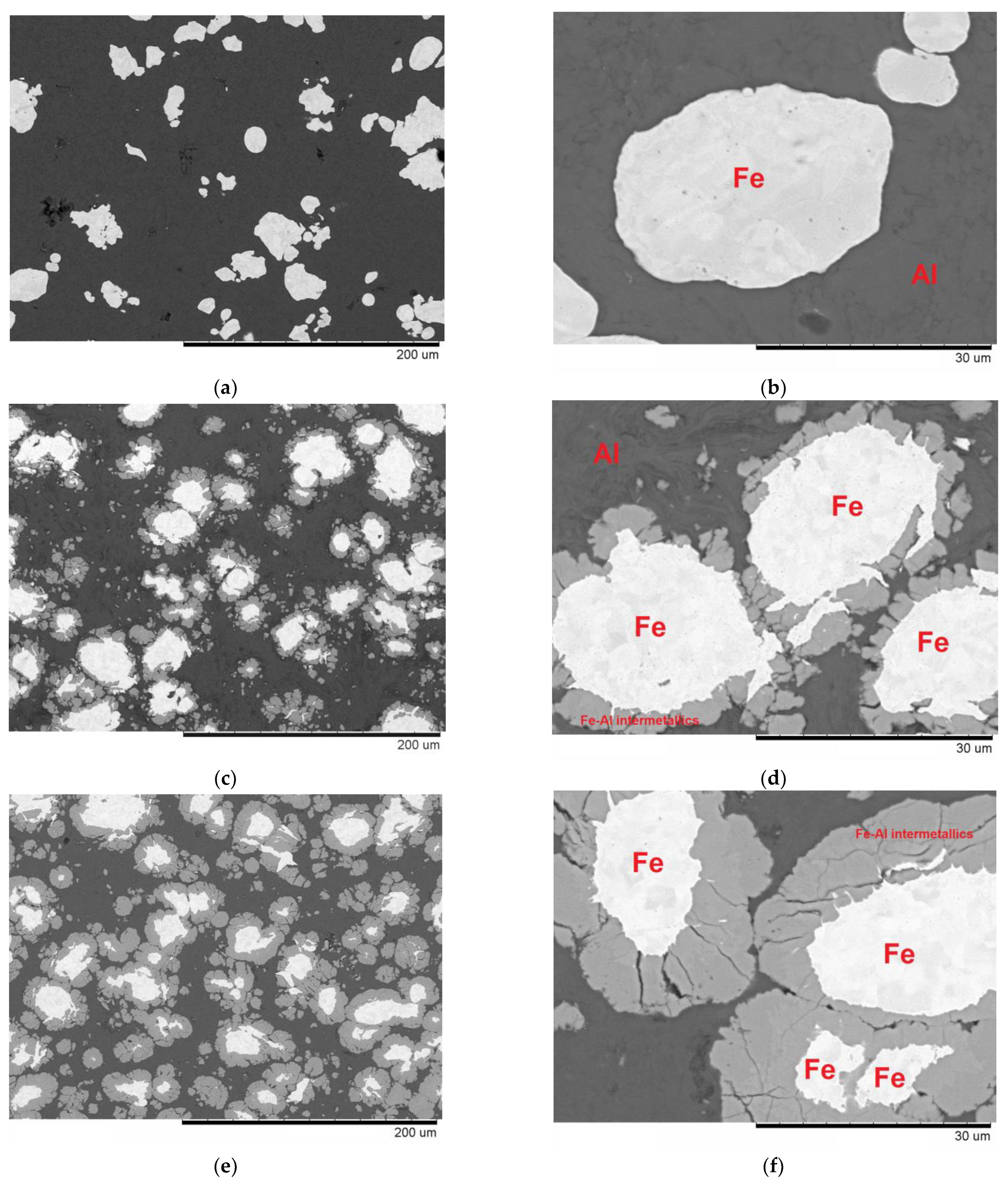
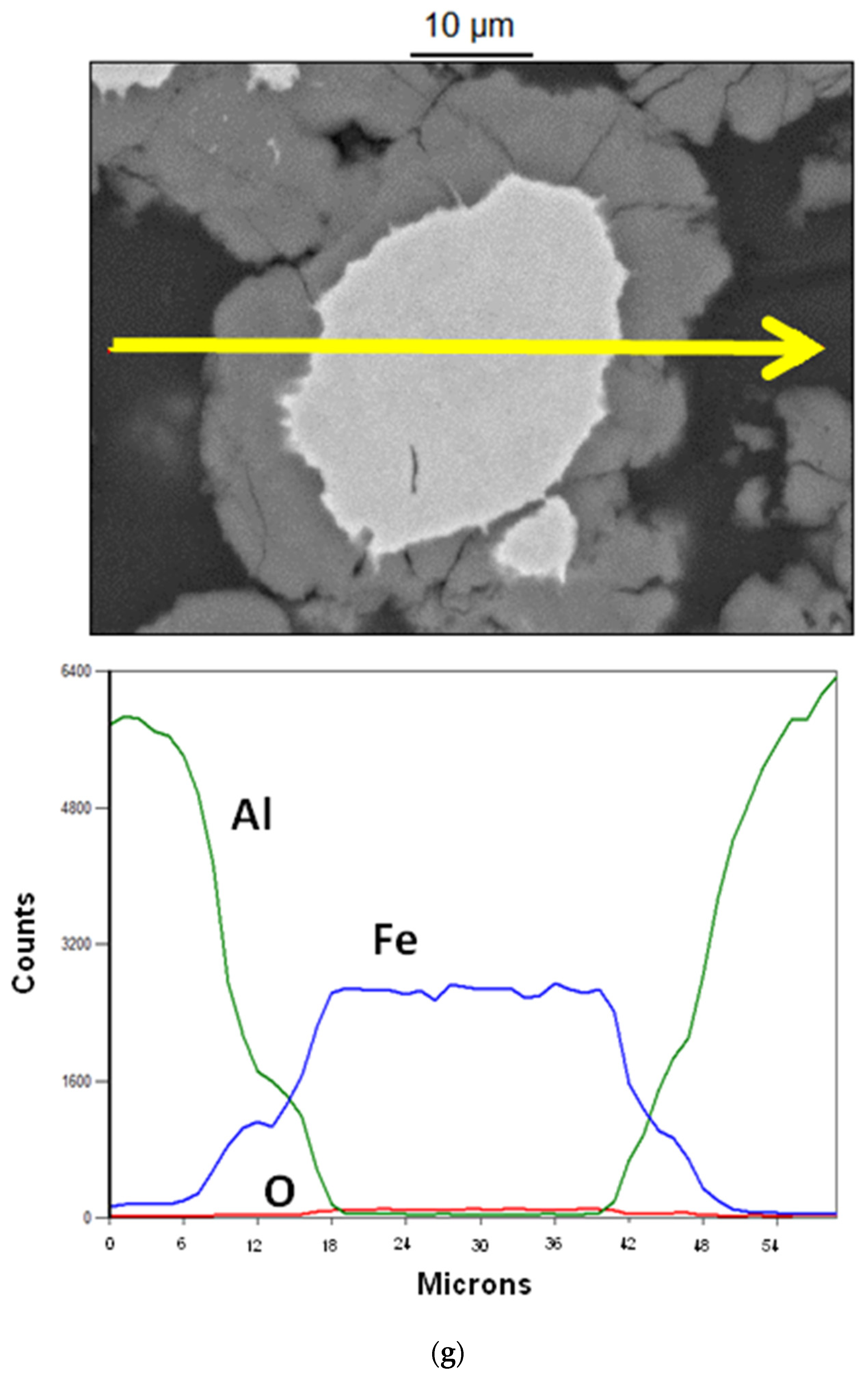
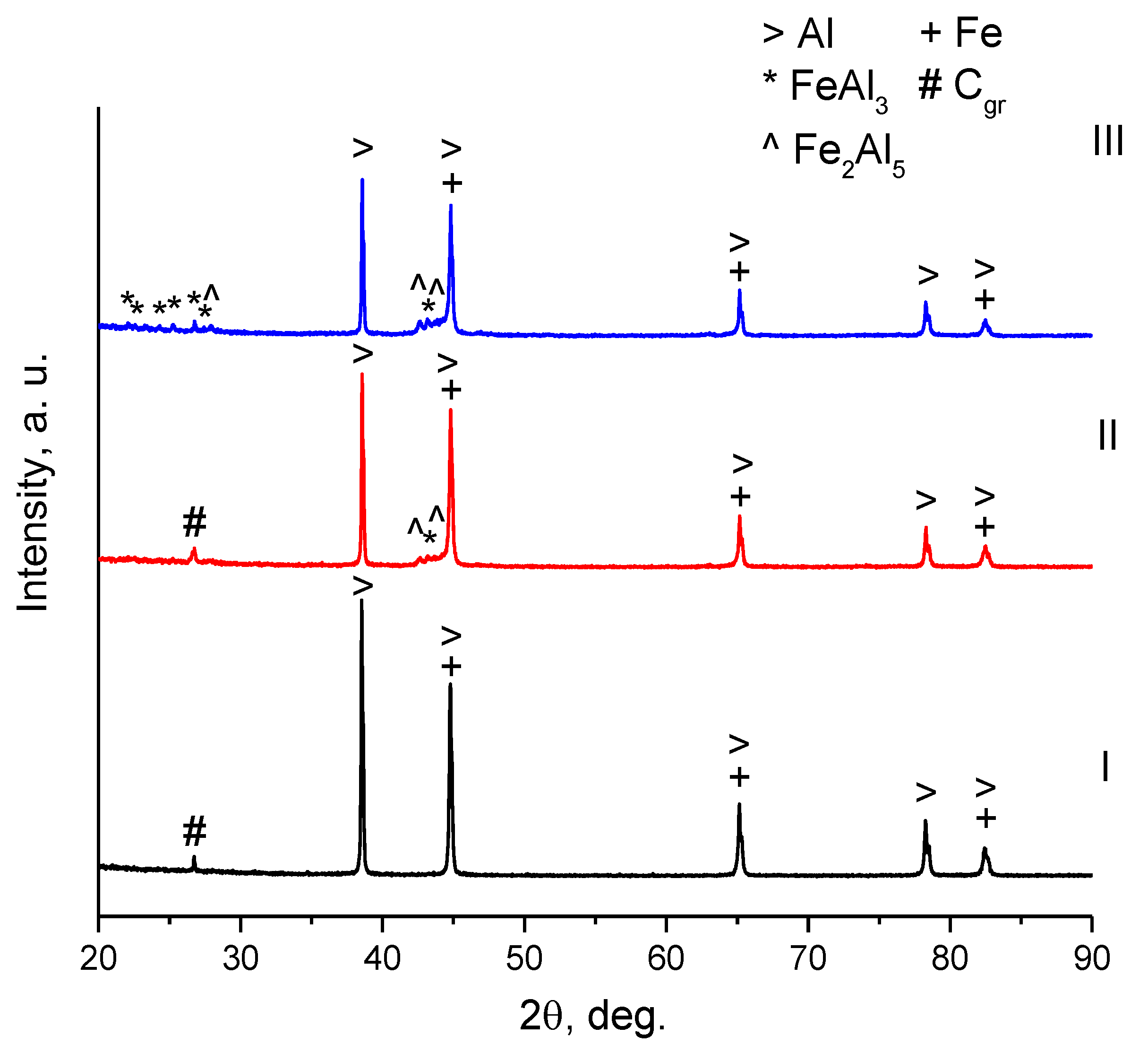
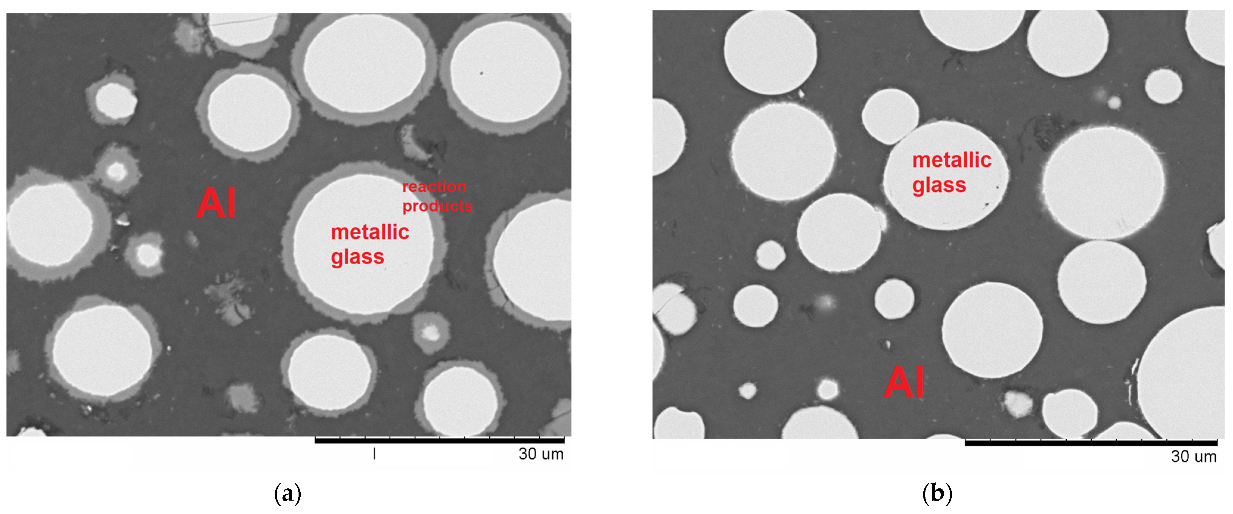
3.1. Reactions at the Al/Fe and Al/Fe66Cr10Nb5B19 Interface during Spark Plasma Sintering

The microstructure of composites formed from the Al + 20 vol.% Fe mixture by SPS at 500 °C and 540 °C is shown in Figure 1 (composites I, II and III). After SPS at 500 °C, the microstructure of the material is formed by the aluminum matrix with embedded iron particles (Figure 1a,b). No reaction layer is observed at the interface between iron and aluminum. The absence of the intermetallic products in composite I was also confirmed by the XRD analysis (Figure 2). SPS of the Al + 20 vol.% Fe mixture at 540 °C for 1 min resulted in the formation of a composite with a thin layer of intermetallic products at the interface between the iron particles and the aluminum matrix (Figure 1c,d). The XRD pattern of composite II shows small reflections of the FeAl3 and Fe2Al5 phases. Composite III was obtained by SPS at a higher pressure, 80 MPa, and demonstrated iron cores covered by thick shells of the Fe-Al intermetallics (Figure 1e,f). The formation of the reaction products at higher concentrations in composite III was confirmed by the XRD analysis (Figure 2). Figure 1g presents the results of the EDS analysis in the line mode for a core-shell particle in the structure of composite III. It is seen that the shell of the reaction products contain both Fe and Al. The core of the particle is still pure iron. The formation of thicker layers of reaction products at 80 MPa can be due to a more intimate contact established between the particles than in the composites sintered at 40 MPa. Interestingly, when the metallic glass was substituted for iron, the pressure increase from 40 MPa to 80 MPa had an opposite effect: while the reaction products were present after SPS at 40 MPa (Figure 3a), no reaction layer was observed in the composite sintered at 80 MPa (Figure 3b). In the latter, only separate fiber-like structures can be detected at the glass/Al interface upon a close examination. The presence of Al, Fe and Cr in the reaction layers formed between the Fe66Cr10Nb5B19 metallic glass and Al was confirmed by the point EDS analysis and elemental mapping in our previous work [45]. The EDS profiles of the interface reported in [46] presented another confirmation.
The effect of pressure on the interfacial reactions during SPS should be discussed in the context of possible overheating at the interfaces in the case of low applied pressures. In [47], the pressure applied during the first (so-called “sparking”) stage of electric current-assisted sintering of an Al-based alloy was lower than the pressure applied at the second stage (main sintering stage). Low pressure at the first stage enabled local melting of the metal, which helped the overall densification of the material. Similarly, materials of a better quality were obtained when lower pressure was used to pre-press an Al-5.7 wt.% Cu powder mixture before subjecting it to an electric current treatment [48]. Alloys with a lower porosity and a lower electrical resistivity were obtained when lower pressure was used to pre-press the compacts. The effect of the pressure applied during the pre-pressing stage was attributed to the formation of microarcs in the sample favored by lower pressures. In [49,50], the problems of evaluating the overheating effect in the inter-particle contact regions were discussed. It was pointed out that the heat dissipation into the particle volume should be taken into account. It was concluded that, for small particles and particles of materials with high thermal conductivity, the overheating of the contacts should not develop under conditions of SPS. However, a relatively low thermal conductivity of the metallic glass (the thermal conductivity of an amorphous Fe80B20 alloy is 10 W m−1 K−1 [51]) can be the factor slowing down the heat dissipation into the particle volume and favoring the development of overheated regions in at the interfaces. In our case, higher pressure applied to the Al + 20 vol.% Fe66Cr10Nb5B19 mixture hindered the reactions by lowering the interfacial electrical resistance and reducing the evolution of heat at the interface. In the Fe-Al system, no evidence of the overheating effect was observed, which can be rationalized by considering a higher thermal conductivity of pure iron (by an order of magnitude) as compared with that of the metallic glass.
The results of the DTA of the glassy alloy powder and pre-pressed mixtures are shown in Figure 4. The DTA trace of the powder of the glassy alloy shows the glass transition and crystallization events with the following characteristic temperatures: the glass transition temperature Tg = 529 °C, the onset temperature of the first crystallization event Tx1 = 565 °C and the onset temperature of the second crystallization event Tx2 = 730 °C. The values of Tg and Tx1 agree well with those determined in [45]. In the trace of the Al + 20 vol.% Fe66Cr10Nb5B19 mixture, the first crystallization peak of the glassy alloy is detected at 565 °C. As the temperature is raised to 595 °C, exothermic reactions between the aluminum and the alloy occur. The second crystallization peak of the glassy alloy could not be detected, as, by the time Tx2 was reached, the alloy was fully consumed in the reaction with aluminum. An exothermic reaction between Fe and Al in the Al + 20 vol.% Fe starts at 570 °C, which marks a so-called pre-combustion event [52]. A sharper exothermic peak follows, beginning at 630 °C and corresponding to a reaction of the combustion type. Further investigations of the composites by the in situ high-temperature XRD (recording XRD patterns during heating of the specimen) are necessary to fully understand the structural changes in the material and the correspondence of the thermal events to the structural evolution path. It should be noted that the conditions of the DTA experiments and those of SPS differ significantly, as SPS is conducted under an applied pressure, which helps establish the interfacial contacts between the components. Also, the heating rate during SPS is higher than that used in the DTA, and higher temperatures may need to be reached to start the reactions during SPS. Nonetheless, the obtained DTA traces help better understand the observed structural changes in the composites upon sintering.
During SPS at 500 °C, the real temperature of the sample is about 530 °C [29], which is still low for the reaction to start. When a SPS process is conducted at a measured temperature of 540 °C, the real temperature is about 570 °C, and the iron particles start interacting with the aluminum matrix. SPS at 570 °C implies sintering at the real temperature of 600 °C, which is just about the temperature required to initiate the reaction between the glass and aluminum. The reactivity of the crystalline Fe66Cr10Nb5B19 alloy was shown to be higher than that of the glassy alloy of the same composition [33]. Unalloyed iron should be even more reactive. Therefore, once the onset temperature of the reaction is reached, the metallic iron particles interact with aluminum faster than the particles of the Fe66Cr10Nb5B19 glass. When SPS is conducted at a moderate pressure (40 MPa), local overheating at the inter-particle contacts facilitates the reaction.
Composites IV and V were synthesized to form structures, in which the load transfer strengthening mechanism could operate, as discussed in Section 3.2. The microstructure of composites IV and V is presented in Figure 5. These composites were obtained by SPS at 570 °C and contain high concentrations of the reaction products. The XRD patterns of the composites confirm the formation of the Fe-Al intermetallic reaction products (Figure 6).

3.2. Mechanical Properties of Composites Derived from Al-20 vol.% Fe and Al-20 vol.% Fe66Cr10Nb5B19—The Influence of the Nature of Added Particles on the Mechanical Properties of Composites

Previously, the compressive properties of the unreinforced aluminum and Al + 20 vol.% Fe66Cr10Nb5B19 composites with thin layers of reaction products were reported in [46]. The glassy particles were not very efficient in increasing the yield strength when no reaction product layers formed at the interface. An increment in the yield strength was about 20% when thin layers of reaction products were synthesized. The Vickers hardness of the unreinforced sintered aluminum (SPS, 540 °C, no holding, residual porosity < 1%) and Al + 20 vol.% Fe66Cr10Nb5B19 composite (SPS, 540 °C, 3 min, thin reaction layer, residual porosity < 1%) was measured to be 40 ± 5 HV1 and 55 ± 5 HV1, respectively.
The estimated Al contents in composites produced in the present work and their mechanical properties are given in Table 2 and Table 3. From the image analysis, the porosity of composites I, II, III and IV is less than 1%. The hardness of composite I is close to the hardness of the unreinforced aluminum, which shows that the mere introduction of iron into an aluminum matrix does not lead to an increase in the hardness of the material (Table 2). The hardness did increase slightly, from 45 ± 5 HV1 (composite I) to 55 ± 10 HV1 (composite II), when the iron particles reacted with the matrix to form thin layers of the reaction products. Consequently, the glassy particles and the metallic iron particles in composites with “core-thin shell” structured micrometer-sized reinforcements produced similar effects on the mechanical properties, just a slight increase in hardness (strength). When a thick layer of the reaction products was allowed to form at the Al/Fe interface, a significant increase in the hardness was achieved, to 100 ± 10 HV1 and 190 ± 40 HV1 for composites III and IV, respectively.
Table 3 presents the mechanical properties of composites derived from the Al + 20 vol.% Fe and Al + 20 vol.% Fe66Cr10Nb5B19 mixtures and having close values of the residual matrix content (composites IV and V, respectively). The hardness of FeAl3 and Fe2Al5 is reported to be 700 HV and 900 HV, respectively [53]. It should be noted that the hardness can vary depending on the grain size and the presence of defects in the microstructure (pores, cracks). The content of intermetallics is high in composites IV and V, so the mechanical properties of the composites should be affected by their presence. The hardness of both composites is much higher than that of the unreinforced aluminum. The hardness and ultimate compressive strength of composite V are higher than the corresponding values of composite IV. The fracture surfaces of composites IV and V are shown in Figure 7. The fracture surface of composite IV is rough, with only a few iron cores that have been cut through upon fracture (Figure 7a). When composite V was loaded, cracks formed in the intermetallic product layer first. As the layer is discontinuous and the interface between the glassy cores and the intermetallic shell is strong, a crack has to cut through the core (Figure 7b) when the stress reaches a certain level. However, in composite IV, the intermetallic component is nearly continuous (Figure 5a). This is due to peculiarities of its growth, namely, non-uniform growth in different directions (due to the polycrystalline nature of the iron particles) as opposed to the formation of nearly ideal spherical shells of intermetallics in the case of the glassy cores (Figure 5b). So, the crack can propagate through the intermetallic component, making composite IV strong enough, but still weaker compared with composite V, in which the glassy cores are present. In a different composite design, the volume content of the glassy component can be high to make a continuous phase. Here, it is important to ensure sufficient cohesion between the glassy particles. If sintered compacts fracture in the intergranular mode in the areas of metallic glass, the cohesion between the grains is lower than the grain strength. If the intermetallic product is not to be in the final composite, the glassy alloy particles should be well sintered to each other to fully benefit from the inherent strength of the glass. Based on results of our experiments, conditions that should be met to form high-strength metallic glass–metal composites can be summarized as follows:
  • The efficient load transfer to the reinforcement should be enabled in the composites, for which the product layer of a certain thickness between the matrix and the reinforcement is required.
  • The intermetallic (shell) component should not be continuous.
  • The glass core/intermetallic shell interface should be strong to avoid the separation of the reinforcement.

4. Conclusions

The results of the present study allow us to draw the following conclusions:
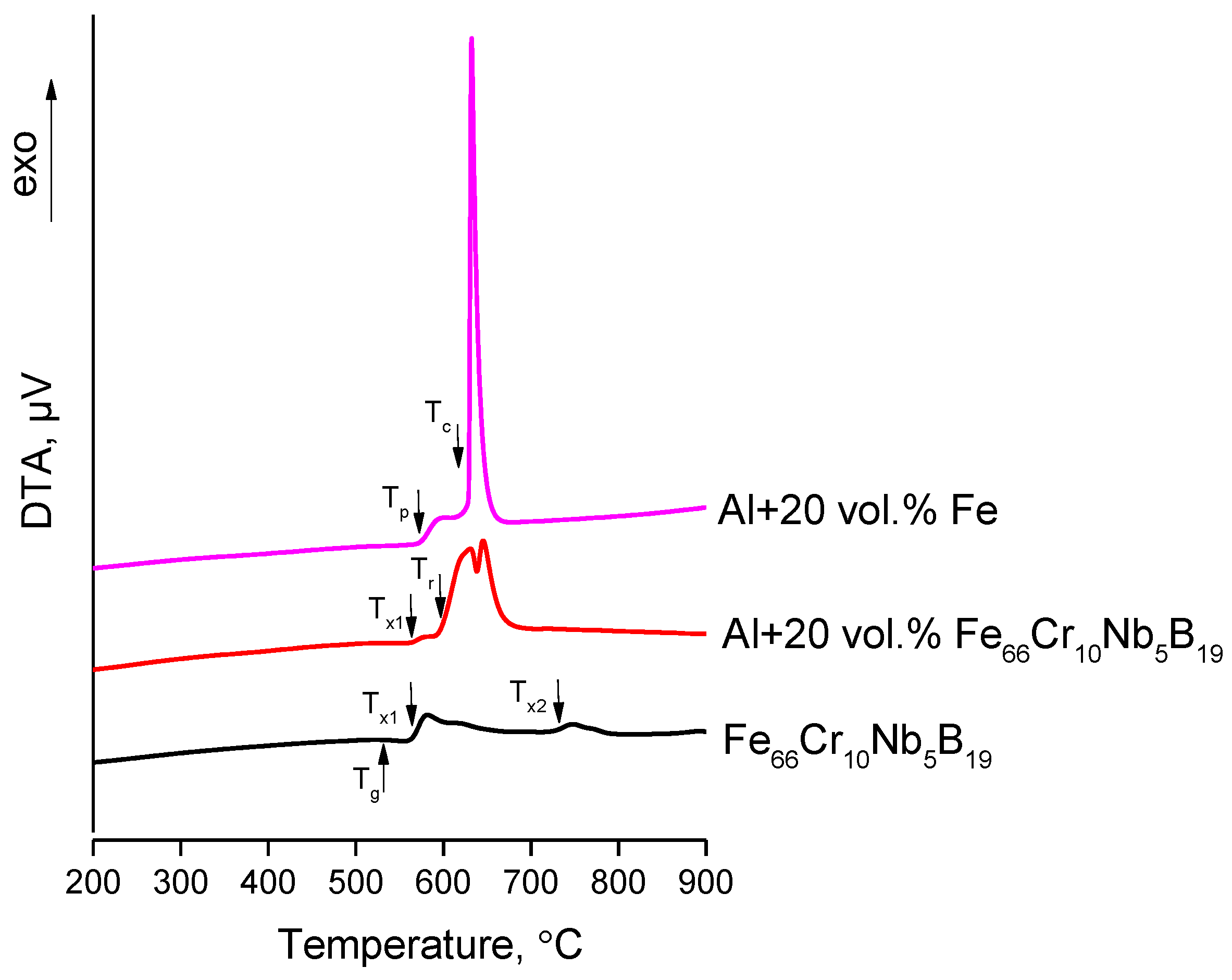
  • Upon conventional heating of the Al + 20 vol.% Fe66Cr10Nb5B19 mixture, the exothermic reaction at the interface starts at 595 °C, while the reaction between Fe and Al starts at 570 °C. Conducting SPS experiments at two different pressures (40 MPa and 80 MPa) allowed us to reveal the formation features of the Fe-based glass/Al and Fe/Al interfaces. Local overheating at the Fe-based glass/Al interface during SPS governed the formation of the product layers at 40 MPa. A higher pressure hindered the reactions by lowering the interfacial resistance in the composite. The opposite behavior was observed in the Fe-Al system—a higher pressure providing a better interfacial contact and facilitating the interaction at the interface. Both SPS temperature and pressure can be used as parameters in the structural design of composites influencing the reactivity of the mixture components.
  • The micrometer-sized particles of iron and metallic glass added at a concentration of 20 vol.% cannot provide significant levels of strengthening to an aluminum matrix. In composites without the reaction products or with thin layers of the products, the hardness of the composite increased by 13–38% relative to the unreinforced sintered aluminum, the added particles of metallic glass and iron producing similar outcomes.
  • The influence of the nature of added particles on the mechanical properties of composites could be seen when the microstructure of the composite enabled an efficient load transfer from the matrix to the reinforcement. This was possible upon the formation of thick layers of the reaction products between Al and the added reinforcement. Upon compressive loading, the composite with the glassy component showed a much higher strength than the composite containing pure iron cores.

Author Contributions

Conceptualization, D.V.D. and K.G.; methodology, V.I.K., B.B.B. and M.A.L.; investigation, A.V.U., A.N.N., A.G.A. and Y.N.B.; resources, A.M.J.J. and G.Y.K.; writing—original draft preparation, V.I.K. and D.V.D.; writing—review and editing, A.M.J.J., A.A.S., K.G. and G.Y.K.; supervision, D.V.D.; project administration, D.V.D.; funding acquisition, D.V.D. and V.I.K. All authors have read and agreed to the published version of the manuscript.

Funding

The support from the Ministry of Science and Higher Education of the Russian Federation, project #121032500062-4 (ISSCM SB RAS) and project #121121600298-7 (LIH SB RAS), is gratefully acknowledged. V.I.K. acknowledges support under the Development Program of Novosibirsk State Technical University (project S23-25).

Institutional Review Board Statement

Not applicable.

Informed Consent Statement

Not applicable.

Data Availability Statement

The data required to reproduce the results of this study are provided in the Materials and Methods section.

Acknowledgments

The authors are grateful to Vyacheslav V. Markushin for his help with the preparation of metallographic samples of the composites, Alexander A. Sivkov for providing graphite tooling for the SPS experiments and Vladimir Yu. Ulianitsky for technical support.

Conflicts of Interest

The authors declare no conflict of interest. The funders had no role in the design of the study; in the collection, analyses, or interpretation of data; in the writing of the manuscript; or in the decision to publish the results.

References

  1. Chawla, N.; Chawla, K.K. Metal Matrix Composites, 2nd ed.; Springer Science + Business Media: New York, NY, USA, 2013; 370p. [Google Scholar]
  2. Casati, R.; Vedani, M. Metal matrix composites reinforced by nano-particles—A review. Metals 2014, 4, 65–83. [Google Scholar] [CrossRef] [Green Version]
  3. Dadkhah, M.; Saboori, A.; Fino, P. An overview of the recent developments in metal matrix nanocomposites reinforced by graphene. Materials 2019, 12, 2823. [Google Scholar] [CrossRef] [Green Version]
  4. Karthik, B.M.; Gowrishankar, M.C.; Sharma, S.; Hiremath, P.; Shettar, M.; Shetty, N. Coated and uncoated reinforcements metal matrix composites characteristics and applications—A critical review. Cogent Eng. 2020, 7, 1856758. [Google Scholar]
  5. Alaneme, K.K.; Okotete, E.A.; Fajemisin, A.V.; Bodunrin, M.O. Applicability of metallic reinforcements for mechanical performance enhancement in metal matrix composites: A review. Arab J. Basic Appl. Sci. 2019, 26, 311–330. [Google Scholar] [CrossRef]
  6. Dudina, D.V.; Georgarakis, K.; Olevsky, E.A. Progress in aluminium and magnesium matrix composites obtained by spark plasma, microwave and induction sintering. Int. Mater. Rev. 2023, 68, 225–246. [Google Scholar] [CrossRef]
  7. Hassan, S.F.; Gupta, M. Development of ductile magnesium composite materials using titanium as reinforcement. J. Alloys Comp. 2002, 345, 246–251. [Google Scholar] [CrossRef]
  8. Leong, W.W.; Gupta, M. Enhancing thermal stability, modulus and ductility of magnesium using molybdenum as reinforcement. Adv. Eng. Mater. 2005, 7, 250–256. [Google Scholar]
  9. Aljerf, M.; Georgarakis, K.; Louzguine-Luzgin, D.; Le Moulec, A.; Inoue, A.; Yavari, A.R. Strong and light metal matrix composites with metallic glass particulate reinforcement. Mater. Sci. Eng. A 2012, 532, 325–330. [Google Scholar] [CrossRef]
  10. Bao, W.; Chen, J.; Yang, X.; Xiang, T.; Cai, Z.; Xie, G. Improved strength and conductivity of metallic-glass-reinforced nanocrystalline CuCrZr alloy. Mater. Des. 2022, 214, 110420. [Google Scholar] [CrossRef]
  11. Chen, T.; Gao, M.; Tong, Y. Effects of alloying elements on the formation of core-shell-structured reinforcing particles during heating of Al–Ti powder compacts. Materials 2018, 11, 138. [Google Scholar] [CrossRef] [Green Version]
  12. Dudina, D.V.; Georgarakis, K. Core–shell particle reinforcements—A new trend in the design and development of metal matrix composites. Materials 2022, 15, 2629. [Google Scholar] [CrossRef] [PubMed]
  13. Wan, Q.; Li, F.; Wang, W.; Hou, J.; Cui, W.; Li, Y. Study on in-situ synthesis process of Ti–Al intermetallic compound-reinforced Al matrix composites. Materials 2019, 12, 1967. [Google Scholar] [CrossRef] [PubMed] [Green Version]
  14. Xue, Y.; Shen, R.; Ni, S.; Xiao, D.; Song, M. Effects of sintering atmosphere on the mechanical properties of Al-Fe particle-reinforced Al-based composites. J. Mater. Eng. Perform. 2015, 24, 1890–1896. [Google Scholar] [CrossRef]
  15. Park, K.; Park, J.; Kwon, H. Fabrication and characterization of Al-SUS316L composite materials manufactured by the spark plasma sintering process. Mater. Sci. Eng. A 2017, 691, 8–15. [Google Scholar] [CrossRef]
  16. Inoue, A. Stabilization of metallic supercooled liquid and bulk amorphous alloys. Acta Mater. 2000, 48, 279–306. [Google Scholar] [CrossRef]
  17. Ashby, M.F.; Greer, A.L. Metallic glasses as structural materials. Scr. Mater. 2006, 54, 321–326. [Google Scholar] [CrossRef]
  18. Yavari, A.R.; Lewandowski, J.J.; Eckert, J. Mechanical properties of bulk metallic glasses. MRS Bull. 2007, 32, 635–638. [Google Scholar] [CrossRef]
  19. Cheng, Y.; Ma, E. Atomic-level structure and structure–property relationship in metallic glasses. Prog. Mater. Sci. 2011, 56, 379–473. [Google Scholar] [CrossRef]
  20. Kruzic, J.J. Bulk metallic glasses as structural materials: A review. Adv. Eng. Mater. 2016, 18, 1308–1331. [Google Scholar] [CrossRef]
  21. Souza, C.A.C.; Ribeiro, D.V.; Kiminami, C.S. Corrosion resistance of Fe-Cr-Based amorphous alloys: An overview. J. Non Cryst. Solids 2016, 442, 56–66. [Google Scholar] [CrossRef]
  22. Burkov, A.A.; Chigrin, P.G. Effect of tungsten, molybdenum, nickel and cobalt on the corrosion and wear performance of Fe-based metallic glass coatings. Surf. Coat. Technol. 2018, 351, 68–77. [Google Scholar] [CrossRef]
  23. Ning, W.; Zhai, H.; Xiao, R.; He, D.; Liang, G.; Wu, Y.; Li, W.; Li, X. The corrosion resistance mechanism of Fe-based amorphous coatings synthesized by detonation gun spraying. J. Mater. Eng. Perform. 2020, 29, 3921–3929. [Google Scholar] [CrossRef]
  24. Jayalakshmi, S.; Sankaranarayanan, S.; Gupta, M. Processing and properties of aluminum and magnesium-based composites containing amorphous reinforcement: A review. Metals 2015, 5, 743–762. [Google Scholar]
  25. Jayalakshmi, S.; Arvind Singh, R.; Gupta, M. Metallic glasses as potential reinforcements in Al and Mg matrices: A review. Technologies 2018, 6, 40. [Google Scholar] [CrossRef] [Green Version]
  26. Georgarakis, K.; Dudina, D.V.; Kvashnin, V.I. Metallic glass-reinforced metal matrix composites: Design, interfaces and properties. Materials 2022, 15, 8278. [Google Scholar] [CrossRef]
  27. Qu, R.T.; Liu, Z.Q.; Wang, R.F.; Zhang, Z.F. Yield strength and yield strain of metallic glasses and their correlations with glass transition temperature. J. Alloys Compd. 2015, 637, 44–54. [Google Scholar] [CrossRef]
  28. Fu, J.; Yang, J.; Wu, K.; Lin, H.; Wen, W.; Ruan, W.; Ren, S.; Zhang, Z.; Liang, X.; Ma, J. Metallic glue for designing composite materials with tailorable properties. Mater. Horiz. 2021, 8, 1690–1699. [Google Scholar] [CrossRef]
  29. Kvashnin, V.I.; Dudina, D.V.; Ukhina, A.V.; Koga, G.Y.; Georgarakis, K. The benefit of the glassy state of reinforcing particles for the densification of aluminum matrix composites. J. Compos. Sci. 2022, 6, 135. [Google Scholar] [CrossRef]
  30. George, E.P.; Raabe, D.; Ritchie, R.O. High-entropy alloys. Nat. Rev. 2019, 4, 515–534. [Google Scholar] [CrossRef]
  31. Torralba, J.M.; Alvaredo, P.; García-Junceda, A. High-entropy alloys fabricated via powder metallurgy. A critical review. Powder Metall. 2019, 62, 84–114. [Google Scholar] [CrossRef]
  32. Cahn, R.W. Atomic transport in amorphous alloys: An introduction. J. Vac. Sci. Technol. A 1986, 4, 3071. [Google Scholar] [CrossRef] [Green Version]
  33. Kvashnin, V.I.; Dudina, D.V.; Bokhonov, B.B.; Petrov, S.A.; Ukhina, A.V.; Georgarakis, K.; Coury, F.G.; Koga, G.Y. Reactivity of a glassy and a crystalline Fe66Cr10Nb5B19 alloy towards aluminum during sintering: A comparative study. Mater. Lett. 2023, 347, 134582. [Google Scholar] [CrossRef]
  34. Tokita, M. Trends in advanced SPS spark plasma sintering systems and technology. J. Soc. Powder Technol. Jpn. 1993, 30, 790–804. [Google Scholar] [CrossRef] [PubMed] [Green Version]
  35. Mamedov, V. Spark plasma sintering as advanced PM sintering method. Powder Metall. 2002, 45, 322–328. [Google Scholar] [CrossRef]
  36. Lee, G.; Manière, C.; McKittrick, J.; Olevsky, E.A. Electric current effects in spark plasma sintering: From the evidence of physical phenomenon to constitutive equation formulation. Scr. Mater. 2019, 170, 90–94. [Google Scholar] [CrossRef]
  37. Saheb, N.; Iqbal, Z.; Khalil, A.; Hakeem, A.S.; Al Aqeeli, N.; Laoui, T.; Al-Qutub, A.; Kirchner, R. Spark Plasma Sintering of metals and metal matrix nanocomposites: A review. J. Nanomater. 2012, 2012, 983470. [Google Scholar] [CrossRef] [Green Version]
  38. Saunders, T.; Grasso, S.; Reece, M.J. Plasma formation during electric discharge (50 V) through conductive powder compacts. J. Eur. Ceram. Soc. 2015, 35, 871–877. [Google Scholar] [CrossRef]
  39. Weston, N.S.; Thomas, B.; Jackson, M. Processing metal powders via field assisted sintering technology (FAST): A critical review. Mater. Sci. Technol. 2019, 35, 1306–1328. [Google Scholar] [CrossRef]
  40. Monchoux, J.P.; Couret, A.; Durand, L.; Voisin, T.; Trzaska, Z.; Thomas, M. Elaboration of metallic materials by SPS: Processing, microstructures, properties, and shaping. Metals 2021, 11, 322. [Google Scholar] [CrossRef]
  41. Abedi, M.; Sovizi, S.; Azarniya, A.; Giuntini, D.; Seraji, M.E.; Hosseini, H.R.M.; Amutha, C.; Ramakrishna, S.; Mukasyan, A. An analytical review on Spark Plasma Sintering of metals and alloys: From processing window, phase transformation, and property perspective. Crit. Rev. Solid State Mater. Sci. 2023, 48, 169–214. [Google Scholar] [CrossRef]
  42. Garay, J.E.; Anselmi-Tamburini, U.; Munir, Z.A. Enhanced growth of intermetallic phases in the Ni–Ti system by current effects. Acta Mater. 2003, 51, 4487–4495. [Google Scholar] [CrossRef]
  43. Li, R.; Yuan, T.; Liu, X.; Zhou, K. Enhanced atomic diffusion of Fe–Al diffusion couple during spark plasma sintering. Scr. Mater. 2016, 110, 105–108. [Google Scholar] [CrossRef]
  44. Abedi, M.; Asadi, A.; Sovizi, S.; Moskovskikh, D.; Vorotilo, S.; Mukasyan, A. Influence of pulsed direct current on the growth rate of intermetallic phases in the Ni–Al system during reactive spark plasma sintering. Scr. Mater. 2022, 216, 114759. [Google Scholar] [CrossRef]
  45. Dudina, D.V.; Bokhonov, B.B.; Batraev, I.S.; Amirastanov, Y.N.; Ukhina, A.V.; Kuchumova, I.D.; Legan, M.A.; Novoselov, A.N.; Gerasimov, K.B.; Bataev, I.A.; et al. Interaction between Fe66Cr10Nb5B19 metallic glass and aluminum during spark plasma sintering. Mater. Sci. Eng. A 2021, 799, 140165. [Google Scholar] [CrossRef]
  46. Dudina, D.V.; Bokhonov, B.B.; Batraev, I.S.; Kvashnin, V.I.; Legan, M.A.; Novoselov, A.N.; Anisimov, A.G.; Esikov, M.A.; Ukhina, A.V.; Matvienko, A.A.; et al. Microstructure and mechanical properties of composites obtained by spark plasma sintering of Al–Fe66Cr10Nb5B19 metallic glass powder mixtures. Metals 2021, 11, 1457. [Google Scholar] [CrossRef]
  47. Crivelli, I.V.; Esposito, E.; Mele, G.; Siniscalchi, A. Formatura per Spark Sintering. Metall Ital. 1973, 65, 611–618. [Google Scholar]
  48. Kol’chinskii, M.Z.; Medvedenko, N.F.; Solonin, Y.M.; Gnatush, F.P. Electric-discharge sintering of mixtures of aluminum and copper powders. Sov. Powder Metall. Metal Ceram. 1977, 16, 504–507. [Google Scholar] [CrossRef]
  49. Ye, Y.; Li, X.; Hu, K.; Lai, Y.; Li, Y. The influence of premolding load on the electrical behavior in the initial stage of electric current activated sintering of carbonyl iron powders. J. Appl. Phys. 2013, 113, 214902. [Google Scholar] [CrossRef]
  50. Collard, C.; Trzaska, Z.; Durand, L.; Chaix, J.M.; Monchoux, J.P. Theoretical and experimental investigations of local overheating at particle contacts in spark plasma sintering. Powder Technol. 2017, 321, 458–470. [Google Scholar] [CrossRef]
  51. Choy, C.L.; Leung, W.P.; Ng, Y.K. Thermal conductivity of metallic glasses. J. Appl. Phys. 1989, 66, 5335–5339. [Google Scholar] [CrossRef]
  52. Sina, H.; Corneliusson, J.; Turba, K.; Iyengar, S. A study on the formation of iron aluminide (FeAl) from elemental powders. J. Alloys Compd. 2015, 636, 261–269. [Google Scholar] [CrossRef]
  53. Matysik, P.; Jóźwiak, S.; Czujko, T. Characterization of low-symmetry structures from phase equilibrium of Fe-Al system—Microstructures and mechanical properties. Materials 2015, 8, 914–931. [Google Scholar] [CrossRef] [PubMed]
Figure 1. Microstructure of composites derived from the Al + 20 vol.% Fe mixture: I (a,b), II (c,d) and III (e,f). The energy dispersive spectroscopy data for composite III: a core-shell particle is analyzed (g). Designation of composites is given in Table 1.
Jcs 07 00302 g001aJcs 07 00302 g001b
Figure 2. XRD patterns of composites I, II and III. The presence of graphite (002) reflection at 2θ = 26.6° is due to the presence of the residual graphite foil adhered to the specimen. Designation of composites is given in Table 1.
Jcs 07 00302 g002
Figure 3. Micrographs of composites sintered from the Al + 20 vol.% Fe66Cr10Nb5B19 powder mixture at 570 °C, 1 min: (a) 40 MPa, (b) 80 MPa. The interfacial reactions were hindered during spark plasma sintering at 80 MPa.
Jcs 07 00302 g003
Figure 4. Differential thermal calorimetry traces of the pre-pressed Al + 20 vol.% Fe and Al + 20 vol.% Fe66Cr10Nb5B19 mixtures and the as-atomized Fe66Cr10Nb5B19 glassy powder. The characteristic temperatures of the thermal events are marked by arrows: glass transition Tg and crystallization onset temperatures Tx1 and Tx2 of the Fe66Cr10Nb5B19 glass, the onset temperature of reaction between the Fe66Cr10Nb5B19 glass and aluminum Tr, pre-combustion temperature Tc and combustion temperature of the Al + 20 vol.% Fe mixture.
Jcs 07 00302 g004
Figure 5. Microstructure of composites: IV (a) and V (b). Designation of composites is given in Table 1.
Jcs 07 00302 g005
Figure 6. XRD patterns of composites IV and V. Designation of composites is given in Table 1.
Jcs 07 00302 g006
Figure 7. Fracture surface of samples tested under compression: composite IV (a) and composite V (b). Designation of composites is given in Table 1.
Jcs 07 00302 g007
Table 1. Materials designation and sintering conditions of composites.
Materials DesignationComposition of the Powder MixtureSPS Temperature, CSoaking Time, minSPS Pressure, MPaSample Diameter, mmNote
IAl + 20 vol.% Fe50004012.5This work
IIAl + 20 vol.% Fe54014012.5This work
IIIAl + 20 vol.% Fe54018012.5This work
IVAl + 20 vol.% Fe57014020.0This work
VAl + 20 vol.% Fe66Cr10Nb5B1957034020.0[45,46]
Table 2. Al matrix content, microstructural features and hardness of composites produced using metallic Fe. The composites vary by the Al matrix content and transformation degrees of the metals into the reaction products.
Material DesignationAl Matrix Content, vol.%Microstructural FeaturesVickers Hardness, HV1Note
I80No reaction layer45 ± 5This work
II60Thin reaction layer55 ± 10This work
III45Thick reaction layer100 ± 10This work
Table 3. Al matrix content, microstructural features and mechanical properties of composites produced using metallic Fe and the Fe-based glassy alloy.
Material DesignationAl Matrix Content, vol.%Microstructural FeaturesVickers Hardness, HV1Ultimate Compressive Strength, MPaFracture Strain, %Note
IV40Thick reaction layer190 ± 40470 ± 103This work
V37Thick reaction layer280 ± 40780 ± 102[26,27]
Disclaimer/Publisher’s Note: The statements, opinions and data contained in all publications are solely those of the individual author(s) and contributor(s) and not of MDPI and/or the editor(s). MDPI and/or the editor(s) disclaim responsibility for any injury to people or property resulting from any ideas, methods, instructions or products referred to in the content.

