Article

The Effect of Ice Floe on the Strength, Stability, and Fatigue of Hybrid Flexible Risers in the Arctic Sea

by
Dimitrii Korotygin
1,
Sathish. K. Nammi
2 and
Ketan Pancholi
1,*
1
School of Engineering, Sir Ian Wood Building, Robert Gordon University, Garthdee Road, Aberdeen AB10 7QB, UK
2
School of Engineering and Materials Science, Queen Mary University of London, Mile End Road, London E1 4NS, UK
*
Author to whom correspondence should be addressed.
J. Compos. Sci. 2023, 7(6), 212; https://doi.org/10.3390/jcs7060212
Submission received: 7 March 2023 / Revised: 9 May 2023 / Accepted: 12 May 2023 / Published: 23 May 2023
(This article belongs to the Section Composites Modelling and Characterization)

Abstract

:
Flexible risers have proven to be a popular choice for deepwater exploration due to their ability to withstand functional and environmental stress while maintaining system integrity. In the challenging arctic conditions, lightweight hybrid composite flexible risers are likely to be employed to mitigate the increase in effective tension. This study investigates the strength and stability performance of production hybrid composite flexible risers with composite pressure armour in the harsh environmental conditions of the Arctic seas. At a water depth of 340 m, the flexible riser was analysed in various global configurations to evaluate the static, dynamic, and lamina-scale performance of its carbon fibre-reinforced thermoplastic polymer composite layer. The drifting ice in the region generated additional load on the riser system, and the effects of this ice on the riser design and its dynamic and lamina-level performances were also analysed. The results indicate that the current riser design incorporating the composite layer is insufficient to ensure system integrity without mitigating the effects of ice loading. The carbon fibre direction in each lamina must be optimised for excess axial stress emanating from the combined action of hoop, axial, and bending stresses. Finally, recommendations on how to improve the life of the lightweight hybrid composite riser in arctic conditions are provided.

1. Introduction

The harsh and extreme conditions in the Arctic region pose new challenges for the technologies and standards established for traditional open water fields, as they may not be suitable for developments in ice-covered waters [1]. Due to the unique challenges posed by the harsh and extreme environment of the Arctic regions, standardisation organisations such as ISO have developed guidelines for the design and construction of offshore structures in ice-covered waters [2]. However, there are currently no specific guidelines for the design and construction of hybrid flexible riser systems containing a carbon fibre-reinforced polymer layer in ice-prone waters. This is considered a necessary development as more major operators are exploring deeper Arctic fields [3]. In deep-water arctic seas, the use of a lightweight hybrid riser is important to alleviate the problem of high effective tension at the hang-off point.
A flexible riser with a Carbon Fibre Reinforced Polymer (CFRP) pressure armour layer is designed to reduce the weight of the riser per metre of length. The materials and dimensions of each layer used in such a hybrid flexible riser have not been widely published due to the limited availability of operational data. However, many experimental and numerical studies of such risers have been published recently [4]. The strength and stability of hybrid risers in arctic conditions have not been previously studied. The ice impact and its influence on the failure of the CFRP layer are unknown. As CFRP layers tend to fail with the initiation of microcracks [5], predicting the early onset of microcracks under the influence of combined axial, bending, and hoop stress can help in the design of the CFRP layer. As a pressure armour, the CFRP composite pipe (layer) is designed to withstand hoop stress (90° carbon fibre orientation). However, the 90° orientation of the fibre cannot withstand the large axial stress of strain due to bending. The minimum bending radius (MBR) is therefore limited to 3.35 m [6], approximately 1.5% strain, to avoid straining the CFRP layers further than the matrix cracking. This is a major limiting factor in the deployment of hybrid risers as production risers.
The hybrid riser system, incorporating the CFRP composite layer serving as a pressure armour, is instrumental in the conveyance of fluids from the subsea manifold to the vessel located in a deep-water setup [4]. This innovative system, if employed as a key component of floating offshore facilities, can be utilised in deep waters such as the Arctic Sea due to its lightweight per metre length [5,6,7,8]. These flexible risers are also characterised by a smooth bore, eliminating the problem of slug flow-induced vibrations [9]. However, the harsh conditions in the Arctic regions, such as the presence of floating ice and low temperatures, present additional challenges for its implementation. The impact of ice on the hybrid riser can result in the formation of microcracks, leading to its failure [5,7]. A self-healing concept has been proposed to address this issue by recovering the microcracks and restoring their fatigue life [10,11].

1.1. Ice Impact Protection Methods for Flexible Risers

The Terra Nova and White Rose, located offshore Newfoundland, Canada, were the first two sub-Arctic subsea projects that deployed an emergency turret system that could be disconnected in harsh environments to mitigate the ice floe impact [11]. Designing the riser system for these projects was challenging due to the shallow water depth of approximately 94 m and the potential for iceberg collisions with a hundred-year storm wave height of 30.4 m. To protect the riser system in the event of extreme weather or an iceberg collision, the turret system was designed to be disconnected, allowing the FPSO to move to a safe location. After disconnection, the buoy was submerged in a mid-water location, changing the entire configuration of the riser system [12,13]. Today, the Terra Nova and White Rose projects are the northernmost offshore developments in the world and the first cylindrical floating production storage and offloading (FPSO) in Norway [3]. The Goliat FPSO [14] has a unique design, with its hull submerged deep enough to avoid interaction with the flexible risers, and it still utilises a turret system that can be disconnected in case an iceberg approaches the FPSO (Figure 1b,c). In such cases, the FPSO disconnects (Figure 1b,c) from its moorings and risers and moves to a safer location. Those case studies show that the presence of ice floes could have a significant impact on the design and fatigue performance of a riser system. To address this issue and comply with ISO 19906 (2010), the operator considered using a submerged turret riser system (STR) for the project [15]. As seen in Figure 1a, the STR system is a modified version of the free-hanging riser system, in which the turret is extended underwater, reducing the interaction between the risers and the ice floes. Additionally, the deep submergence of the turret was able to mitigate the effects of the low temperature of the surface water. It was also connected with an underwater buoy and integrated bearings. However, the challenge was to determine the appropriate depth to submerge the turret to eliminate ice-riser interactions. It was recommended to increase the typical turret height of 12–18 m to 30 m to ensure that the top sections of the risers remained secure [3]. The metallic structure of the turret must be large in diameter to accommodate all the risers, and, therefore, its weight per metre is substantial, affecting the design and cost of the Floating Production Unit (FPU) [3]. Researchers [15] raised concerns about the limited operational experience in the region and the high uncertainty of the data on ice and icebergs. Some icebergs may become frozen in the drifting ice, making them almost impossible to detect using satellite technology, particularly if they are small.
The mooring system of the Floating Production Unit (FPU) has been reported [17] to be capable of tolerating the impact of an iceberg weighing up to 1 million tonnes travelling at a drift speed of 0.6 m/s. However, the keel installation may come into contact with ice ridges, which could cause damage to the riser and lead to continuous wear and tear. To mitigate these impacts, a system with rubber protection has been proposed. While this solution may reduce the effects of an iceberg collision, it has its limitations, as the rubber can lose its elasticity at low temperatures, particularly during the transfer of cryogenic liquified natural gas through a flexible riser [18]. Additionally, fragments of icebergs or ice floes may still penetrate under the extended turret and collide with the risers, even if the collision is unavoidable. If disconnecting the riser buoy in an emergency situation is impossible or occurs too late, the mooring system may be forced to absorb the impact. However, the geometry of the disconnectable riser system and extended turret may make it difficult to remove the ice floes from beneath the riser buoy, as they may remain there until they melt, which could take several months. Another scenario to consider is that ice floes could be driven under the buoy during a 100-year storm, when waves reach their highest levels [19].

1.2. Numerical Models for Hybrid Risers

The concept of an armoured riser was proposed to alleviate the problem of ice floe impact. To test the concept, the response of the riser and its armour to the impact of an ice block was analysed. A simulation of the floating ice load on flexible risers protected by armour was performed [10,11,20]. In the dynamic model, the armour was modelled as cylindrical hollow elements connected to each other to capture its large deformation. The results showed that the deformation of the armour was able to absorb the energy of the ice impact. However, the minimum bending radius of the armour was required to be kept far larger than that of the riser it covers. This issue could also occur in thermoplastic multi-layered umbilical High-Voltage Direct Current (HVDC) cables [21,22] capable of transmitting a high-voltage current from offshore wind turbines.
Modelling a hybrid riser with a CFRP layer would require global and local models to pick up the microscale failure in the CFRP pipe. Finite Element Analysis (FEA) using an Ansys® ACP pre-processor [23] is widely used for multiscale modelling. Previously, the Ansys® was used to analyse a composite cylinder under various loading conditions, using Tsai-Wu as the failure criterion. The importance of finding the correct parameters could be difficult, as these have a major impact on the failure method. Maximum stress theory is a useful but conservative method that predicts failure when one of the many stress components along one of the principal material axes reaches the magnitude of the corresponding material yield strength in that direction. It is also important to use the correct failure criteria within Ansys® to take the stress interactions within the different failure mechanisms into account.
The failure criterion for the flexible risers without composite pressure armour (Figure 2a) is useful, as it can easily predict the ultimate failure. However, when flexible risers are incorporated with the CFRP pipe layer (Figure 2b) to replace the steel pressure armour in the conventional flexible riser, estimating the failure of this new hybrid riser becomes difficult due to the orthotopic properties of CFRP. It is best to predict the matrix microcracking initialisation when a great enough load is applied to a laminate structure or a singular ply. These microcracks occur transverse to the direction of the load and can be induced by point loads, cyclic loads, or thermal changes. Matrix cracking is often the first form of laminate failure [24] and as such, it needs to be accounted for. The onset of cracking reduces the effective modulus of the laminate and will result in failure at a lower load than that predicted without the onset of cracking [25]. Multiscale modelling is the way forward to predict failure. Finding the maximum bending moment of the flexible pipe at the global scale and transferring the loading to composite pipe at the local level would allow predicting [26] microcracks if the failure criterion is set using Puck’s or Hashin’s criterion [27].
In this work, the impact of floating ice on the strength/failure/fatigue of hybrid composite flexible risers, designed to be protected from floating ice by an extended turret, is estimated through simulation. This evaluation considers the effects of the Arctic environment on the hybrid composite riser, specifically its impact on strength and stability performance. In global analyses, sea current loading and sliding contact at the touch-down zone (TDZ) determine the kinetic stability at the mudline. Any instability would be picked up during the static solution, and the end section in the touchdown zone would loop. The simulation considers various ice characteristics and sizes for a given riser cross-section configuration, internal diameter, and meteorological data for the field location. Both local and global models using AnsysR18.1 and OrcaFlex® 10.2d [28] were developed to predict failure due to environmental and ice loading. The bending moment was extracted from OrcaFlex® global models and applied to Ansys ACP [29] with Puck’s failure criterion and maximum stress criterion.
Figure 2. (a) A schematic showing conventional flexible riser [4] (b) a schematic showing the carbon fibre reinforced polymer composite pipe that replaces the steel pressure armour in flexible riser making a hybrid flexible riser [30].
Jcs 07 00212 g002

2. Analysis Methodology

The static and dynamic finite element analysis methodology was used to predict the effect of ice floes on the hybrid flexible riser as well as the composite layer within it. Firstly, the static and dynamic global analysis was performed on the entire flexible riser length (approx. 828 m) installed under the sea using OrcaFlex®. Different configurations of flexible risers were analysed in OrcaFlex®, and all stresses were minimised. All results, such as bending moment and effective tension, were extracted from global models of the entire line of flexible risers and the most conservative values of all loads applied on the 1 m-long section of the CFRP (Figure 2b) pressure armour model for local static analysis. This all allowed us to analyse the effect on the CFRP pressure armour of the hybrid flexible riser in a worst-case loading scenario. The composite layer of the hybrid riser was analysed using the Ansys ACP package, which is integrated with a mechanical analysis package. This allowed us to model pre- and post-analyses of the layered/laminate composite modelling. First, the global static and dynamic analysis methodology is presented in the sections below. Subsequently, the local FEA static analysis methodology of the 1 m-section composite layer bonded with a PA-12 polymer inner layer is presented in the analysis.

2.1. Global Analysis

The purpose of the global analysis of the riser system is to evaluate the overall response of the riser system to the combined loads acting on the riser system. In the first stage, the appropriate riser configuration was selected by running a static analysis. Afterwards, the integrity of the riser system during the extreme environmental loadings was verified by running the extreme dynamic analysis. Additionally, the riser system may be subjected to extreme events such as damage to the mooring system. Most onerous bending moments, axial stresses, and hoop stresses were extracted from the global analysis and applied to the local FEA model. The 8” flexible hybrid riser with the CFRP pressure armour layer was modelled in OrcaFlex®. The smeared buoyancy was used throughout the analysis [31]. All dimensions and material information were derived from previous work [4].
The flexible riser shows nonlinear bending behaviour due to layer slipping and, in particular, helical strips slippage. The loxodromic and geodesic curve analysis established the nonlinear curvature-bending moment relation [32,33]. For this nonlinear bending moment, curvature relations were captured from Equations (1) and (2) based on the friction-limited slippage between each layer [4]. The critical curvature represents the curvature radius of the flexible riser when the helical strip of the tensile layer starts slipping to reduce the effective overall bending stiffness.
M = E I β 2
β 2 c = 1 + s i n 2 α   E A k R 2 μ q 3 I + q 3 I + 1 E A   c o s 2 α   sin α
Here, M is moment, EI is bending stiffness, β2 is curvature radius, critical curvature is β2c, and the helix angle is α. The parameters q3, k, and R for each layer are radial load, stiffness, and radius, respectively [34]. This nonlinear relation with curvature and bending moment was added to OrfcaFlex® 10.1d to set up a global hybrid flexible riser model, and further analysis was carried out: first static, then dynamic.

2.1.1. Static Analysis

The loadings considered for the static analysis are gravity, internal fluid, vessel offset, current loadings (data are provide in Table S4), and buoyancy. The current in the same direction of the vessel heading is defined as the 0° current. The current in the opposite direction of the vessel heading is defined as the 180° current, and the current 90° to the vessel heading is defined as the cross current. According to API [35], the current and wind loading for the static analysis is taken for a 100-year return period. The vessel offsets considered for the global analysis are presented in Table 1. The parameters used for wind, turret, mooring lines, the sea state scatter diagram, hydrodynamic coefficients of the riser, and soil riser interaction are provided in the Supplementary Materials (Tables S1–S5).
The vessel offset is described in three positions: normal position (zero offset), near offset, and far offset, Figure 3. As the catenary mooring system is used, the distance of the operational vessel offset is considered as 10% of the water depth (340 m), which is about 34 m. One broken mooring line is considered to be an accidental condition, and the maximum vessel offset in the near and far positions is 12% according to the vessel offsets used in the global riser analysis.
Six types of flexible riser global configurations were analysed: Catenary, Lazy wave, Steep wave, Lazy S, Steep S, and Pliant wave configurations. Ultimate limit state (ULS) refers to the normal operational conditions, Accidental Limit State (ALS) refers to the operation with one mooring line being broken. After each case of simulation, the Minimum bending radius along the riser line, effective tension at the turret connection, effective tension at riser end termination (PLET), bending moment at the turret connection, and effective tension at touchdown point (TDP) are generated numerically for each load case.

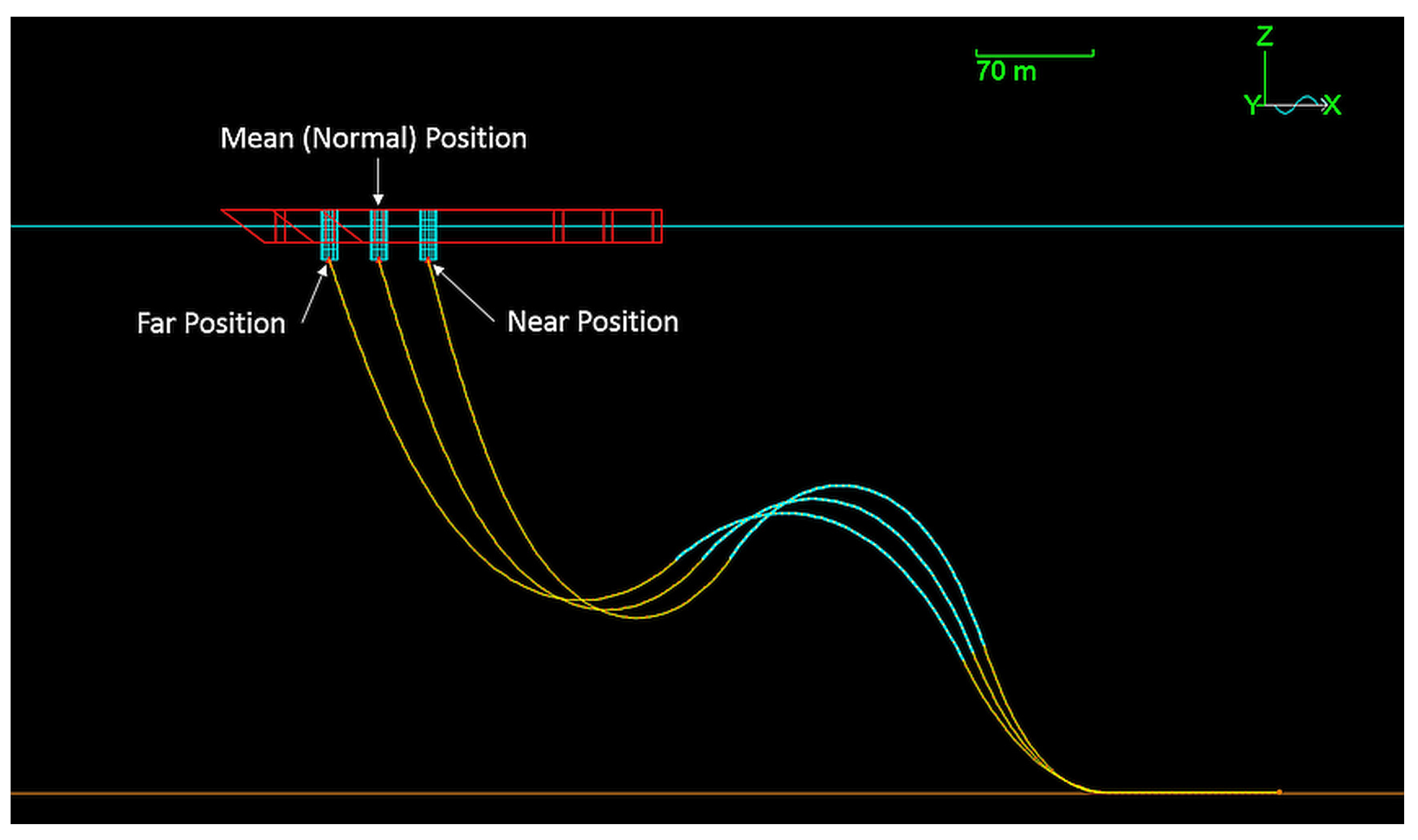
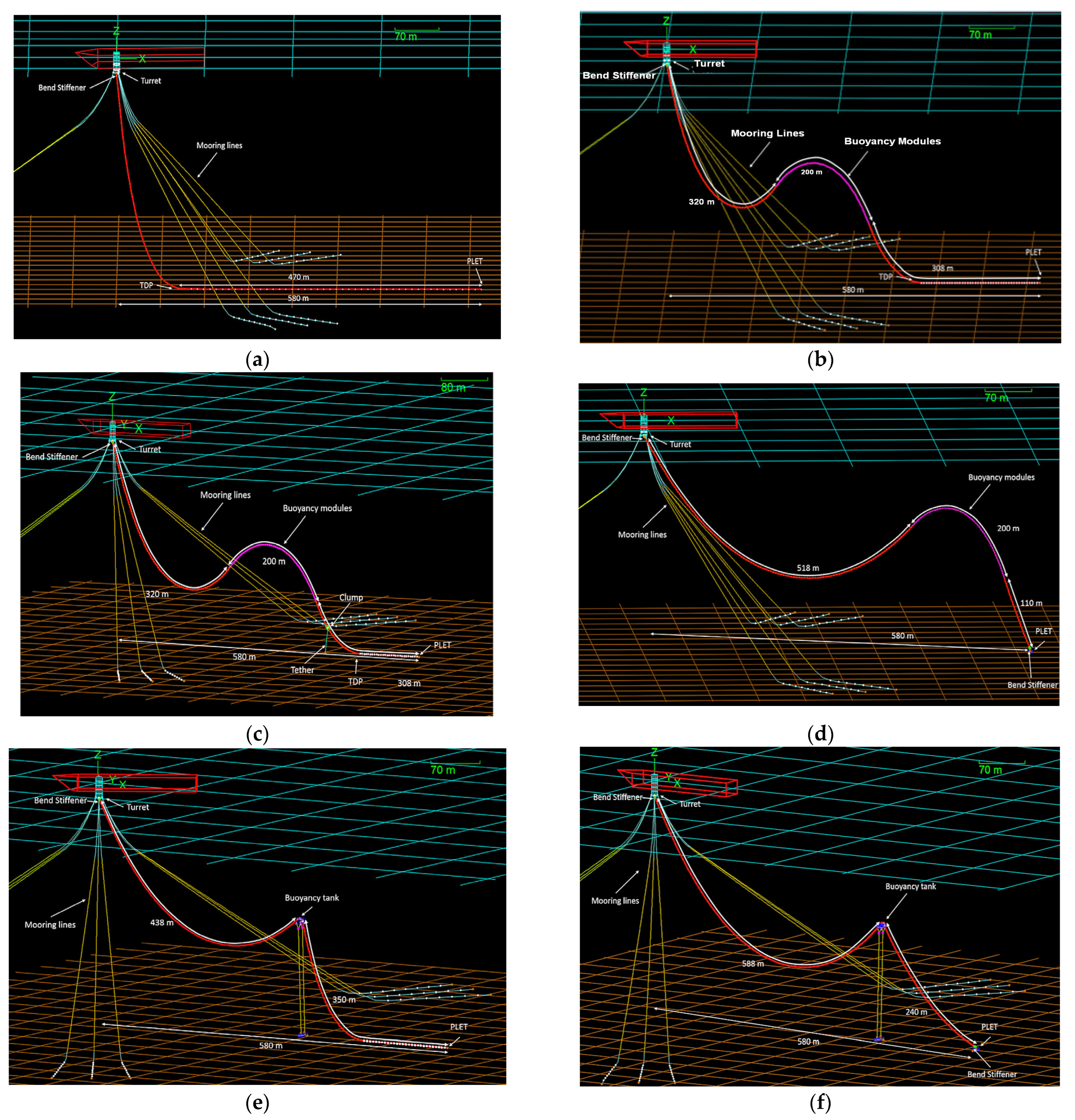
2.1.2. Load Cases for Riser Configurations

The configuration of the flexible riser has been modelled based on water depth, vessel data, position of PLET relative to the FPU, and flexible riser data. In steep wave configuration, the mean FPU offset was also added along with the bend stiffener at the lower-end connection. The added bend stiffener was also found in steep S wave but with the buoyancy tank section, as found in the lazy S configuration.
The load cases considered for the analysis are shown in Table 2, where ULS (ultimate limit state) refers to a physical condition that includes excessive deformations leading to collapse, whereas ALS (accidental limit state) corresponds to the situation of the riser that, if exceeded, indicates loss of structural integrity initiated by accidental load, respectively. The riser is either considered empty without any internal fluid or fluid level corresponding to the operating condition, or annulus of pipe flooded with seawater. FPU offset is considered based on RAOs, as shown in Table 1. The current direction with respect to FPSO is also mentioned in Table 2. All the key dimensions and features are included in Table 3. The hang off angle with respect to its turret is fixed on top. The upper section length is the riser length from the hang off point at the top to TDP. The configuration images of all the analysed models are shown in Figure 4. According to DNV [36], the sag bend, hog bend, and TDP areas are critical for the lazy wave configuration, whereas the pliant wave configuration have added features such as an anchored tether on the seabed near the touch down point. Additionally, the following parameters must be studied for this configuration: (1) horizontal displacement from the FPU turret to the tether anchor; (2) arc length from the turret to the clump on the flexible riser; and (3) the length of the tether.

2.1.3. Dynamic Analysis

After performing the static analysis, the next stage is to perform the dynamic analysis to evaluate the dynamic global response of the selected flexible riser configuration. The load cases combine different FPU positions and motions, riser content densities, wave, and current conditions to provide the overall assessment of the riser suitability to operate in the extreme environmental conditions of the Arctic. Table 4 represents several different load cases for the dynamic analysis. The results of the dynamic analysis will be studied and compared with riser’s load limits. Then, the worse load case will be run additionally with included floating ice in the model to analyse the effect of the ice load on the dynamic response of the riser.
Similar to the static analysis, the current in the same direction of the vessel heading is defined as the 0° current. The current in the opposite direction of the vessel heading is defined as the 180° current, and the current 90° to the vessel heading is defined as the cross current. The waves in the same direction of the vessel heading are defined as the 0° waves. The waves in the opposite direction of the vessel heading are defined as the 180° waves, and the waves 90° to the vessel heading are defined as cross waves. The current, wind, and wave design environmental loading for the extreme design analysis is taken for a 100-year return period [35], the worst condition for the top section of the riser in the cross position of the vessel, and the wave direction. As the FPU is free to rotate around the turret, the vessel will position itself along the wave propagation direction. The results of MBR, effective tension at vessel–riser interference and tension at PLET, TDP, and tether are extracted. The simulation time based on the maximum wave distribution of the irregular wave profile for 10,000 s was used.

2.1.4. Load Cases with Floating Ice Configurations

The load case that gave the worst results for the dynamic analysis was simulated with floating ice added to the model. The floating ice was modelled as 6D buoy with a size of a cube with 3 m × 3 m × 3 m demotion. The size of the ice floe is considered of that size because it could be the smallest with average stiffness. The stiffness properties were assigned to buoys by creating shapes with the size and density of the stiffness of ice. The stiffness of ice was taken as the most conservative for multi-year ice. This load case simulated the physics of the floating ice that was driven under the turret to collide with the riser. The riser armour protection was modelled based on the information provided in the literature [20]. The modelled amour segment length was 0.6 m, and its density in the air was 669 kg/m3 with the MBR of 4.4 m. The images of the riser and ice with and without the armour are shown in the Figure 5. The ice stiffness considered for the ice was 1 × 10⁹ N/m/m2, whereas buoys stiffness was 10 times stiffer than the riser [15].

2.2. Local Analysis

The CFRP bonded pipe (pressure armour) was modelled considering 40 layers of CFRP layers and 1 thick layer of the PA12 polymer layer [4,37]. The thin wear protecting layers (polymer sheaths) were not included in the model (Figure 2b). The model was prepared in the Ansys 2018, ACP pre-processor. The orthotropic material properties were for the CFRP layer, whereas the thickest polymer layer (0.0984 in) was for the PA-12 properties.
The axial stiffness of the bonded pipe model was insignificant in relation to hoop direction for the CFRP layer, where the carbon fibre direction was assumed to be 88° and 0° in the alternate layer, as shown in Figure 6.
The material properties for each layer and dimensions were derived from the previous study [4] and the rule of mixture equations was used to estimate the mechanical properties of the individual ply of the CFRP [38]. The tensile strength of the carbon fibre (60%) and thermoplastic PA-6 (40%) was considered by estimating the total tensile strength and stiffness modulus of each ply. The Poisson ratio for the ply was estimated to obtain the equivalent to the PA-6. The composite section of each layer thickness and the combined material properties derived from the Ansys model are shown in Table 5 and Table 6, respectively.
Using the composite pre-processing module (ACP), the local 3D model for the bonded composite pipe made up of CFRP unidirectional tape was prepared. The module assigns the material properties and defines the CFRP layup. This CFRP layer is coupled with another polymer (PA-12) layer. The addition of the frictional contacts resulted in a nonlinear model. The inner polymer layer considered elastic isotropic material, whereas other layer materials and properties were modelled as mentioned in [4]. Mesh was converged with an element size of 20 mm, giving a total of 162,842 elements. The following mesh gave results which were 0.398% different, suggesting the 20 mm mesh was accurate. The shell elements were stiffer than the solid ones; however, their contact tolerance was less than 4%. The friction for contact was chosen to be 0.15 in this study. All analyses were performed using frictional contact configurations and ovality of the composite layer was estimated. The augmented Lagrange formulation was adopted where friction force was estimated with Equation (3).
K c × x p + λ
Here, Kc is contact stiffness, xp is penetration, and λ is LaGrange multiplier. It is accepted as the best practice that a minimum of three second order quadratic elements are required through the thickness to accurately determine stiffness and stresses.

2.2.1. Assumptions

The following assumptions were made.
All analyses consider a 1 m (39.4 in) length pipe model in the local model.
Material has anisotropic (orthotropic) material properties applied as each ply properties calculated from the rule of mixture equation (60% carbon fibre and 40% PA6).
Temperature effects on materials are not considered.
Remote displacement is used, allowing for deformation at the constraints.
Equal bending moment was applied on both sides of the pipe, resulting in symmetric loading.

2.2.2. Loading

As seen in Figure 7, axial loading was also applied to the composite section. The composite is modelled as the layers of CFRP are combined with the polymer (PA12) pipe. The inner polymer layer of the composite in Ansys® is considered as a thick layer to make up the riser ID. Although the tensile armour will take the majority of the axial load, the composite section will also bear ~5% of the total tension, as seen in the local model. The contact pressure due to friction transfers the tension between layers due to engagement between layers. Using the relation between wall tension and effective tension as well as internal pressure and external pressure, the tension transfer on the composite layer was estimated. The pressure multiplied by the area of the layer was considered to calculate the tension force. The friction constant between layers was 0.1. To validate, a local 2D model of all layer-flexible risers was constructed to determine the load share experienced by the various layers of the composite flexible riser. The failure criteria were then applied to the ACP model to retrieve the failure region. The maximum effective tension was calculated through Global analysis and the results analysed using local analysis.
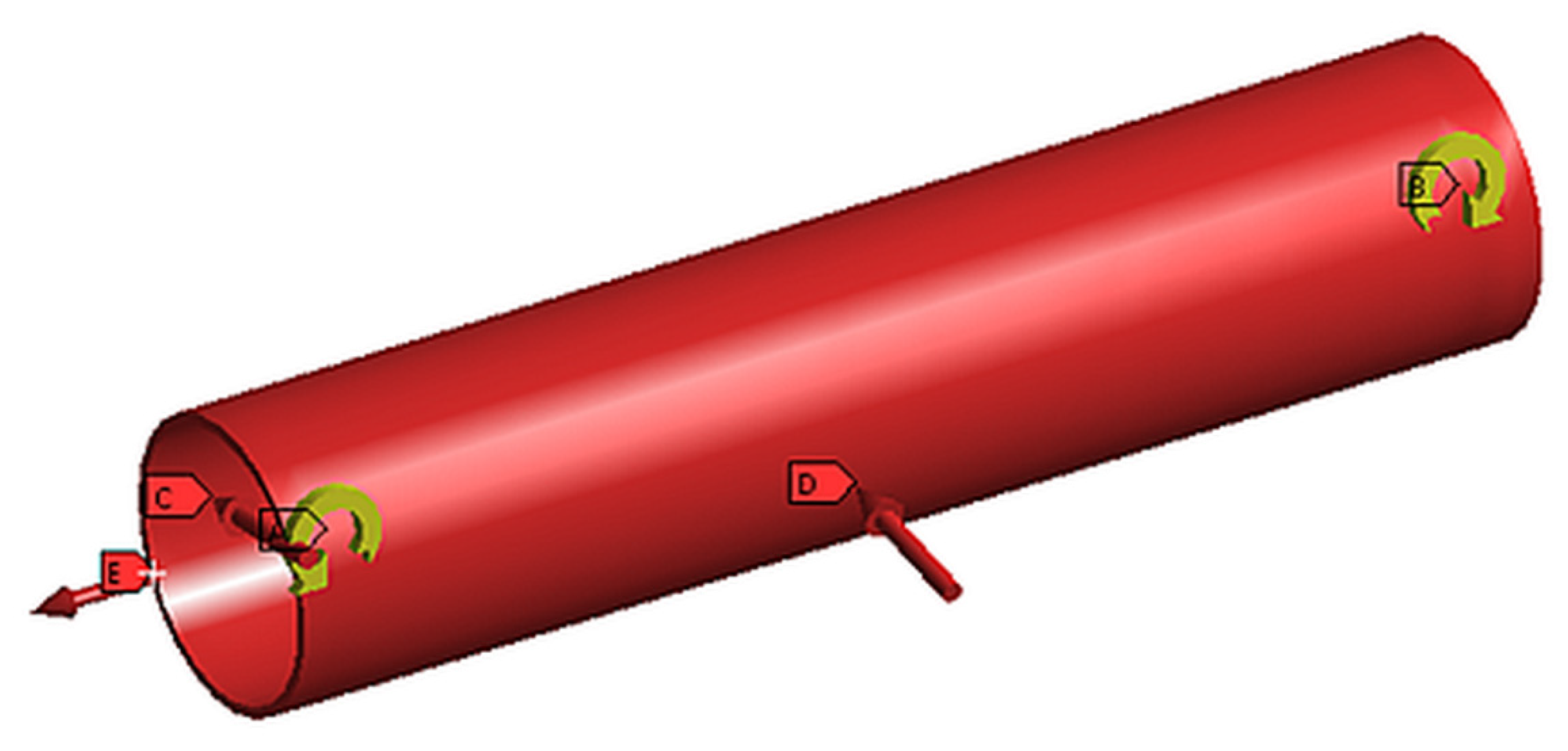
Maximum bending radius applied to 1 m section—taken from global analysis. The radius was measured from the centre of the flexible pipe and extrapolated the radius to the CFRP pressure armour. Subsequently, the equivalent moment was applied to achieve the radius of the CFRP pressure armour, as calculated using extrapolation. The sliding boundary conditions were set at one end of the CFRP pipe, while the moment, axial loads, and torsional loads were applied at the other end with degrees of freedom in the x and z directions.
Design pressure was applied to the internal surface (34.47 MPa)
External Pressure was applied to the depth where the MBR occurred, taken from the global analysis. The external pressure value is equivalent to the column of the water at the depth taken from the pressure force absorbed by the displacement of layers above until equilibrium is found with internal pressure.

3. Results and Discussion

The global static and dynamic analysis results along with the local model results are presented in this discussion. A total of 24 load cases (Table 2) for hybrid flexible risers were analysed and a further 18 load cases with minimum stresses were further analysed dynamically. All results, such as bending moments, effective tension at various locations along the riser length, and minimum bending radius were derived and compared with acceptable values to evaluate the most conservative loads for an acceptable riser configuration. The most onerous stresses derived from the global dynamic analyses were further applied to the local Ansys model to estimate microcracking and early failure. From a damage tolerance point of view, the estimation of microcracking is important. These details are discussed in the following sections.

3.1. Static Analysis Outcomes

All results are presented in Tables S5–S10 in the Supplementary Materials. The worst-case static analysis results for catenary, lazy wave, pliant wave, steep wave, lazy S, and steep S wave configurations are presented in Table 7. Case 15 with an empty pipe, near FPU offset, and one broken mooring line was the worst for the lazy wave riser configuration, as it had an MBR of 6 m and the highest BM at the hang off point, whereas the case 3 with the empty pipe and near FPU offset was worse for the pliant wave riser configuration (bending radius, 10 m, and the highest bending moment at the hang off point). In the case of steep wave, case 15 (MBR 6 m, highest BM and effective tension at hang off) with the empty pipe, near FPU offset, and one broken mooring line was found to be the worst. In contrast to all these results, case 24 with the flooded pipe, cross FPU offset, and one broken mooring line was found to be worse for the lazy S and seep S riser configuration (Lazy S- MBR 13 m and the highest BM and the highest effective tension for the hang off, Steep S -MBR 5 m, high bending moment at PLET, high effective tension and bending moment at hang off point). The minimum allowable bending radius for the pipe is 3.6 m. From the static analysis performed on six flexible riser global configurations, several challenges for flexible risers arose:
The minimum bending radius (MBR) did not exceed the limit for a given cross section, but the composite layer reached low values for lazy wave, steep wave, and steep S global configurations.
Different operation modes with a pipe filled with seawater and an empty pipe generate high differences in top tension and MBR values.
The following conclusions were made based on the results from the static analysis on six types of global flexible riser configurations:
The catenary configuration has good results for MBR but it has minimum tension at TDP that can generate compression force in dynamic mode and early fatigue for the riser.
Lazy wave configuration has lower top tension due to the effect of distributed buoyancy but it has very low MBR and the highest bending moment at hang off point of the riser
The plait wave configuration has high MBR and low effective tension at the vessel-riser interface and low effective tension at PLET. The bending moment at the vessel-riser interface is relatively high but it is more than tree time less than the maximum bending moment allowable for this riser. The effective tension is lower than for lazy S configuration, but due to the presence of the tether, the oscillation of the pipe due to the vessel heave is limited.
Steep wave configuration has high effective tension at PLET and very low MBR, as well as high bending moment at vessel-riser interface.
The lazy S configuration has relatively low MBR but the highest effective tension at vessel-riser interface due to concentrated buoyancy at the mid-water arch.
The steep S configuration has low MBR, high bending moment, and high effective tension at the riser hang off point and PLET
So, based on the static analysis, the pliant wave configuration with the most conservative results was selected for further analysis (dynamic analysis and local analysis), as it showed low MBR relative to the other evaluated parameters measured for the rest global riser configurations. Even after providing torsional moment to the riser in the Touchdown zone (TDZ) section, instability was not observed in most cases. No configuration was taken forward if looping in TDZ was observed.

3.2. Dynamic Analysis Results

The load cases combined different FPU positions and motions, riser content densities, and wave and current conditions in order to provide an overall assessment of the riser’s suitability to operate in the extreme environmental conditions of the Arctic. The results of the dynamic analysis were studied and compared with the riser’s load limits. Then, the worst load case was run additionally with the included floating ice in the model to analyse the effect of the ice load on the dynamic response of the riser.
Dynamic analysis results for MBR along the length of the riser are presented in Table S11 in the Supplementary Materials, while the tension at the turret connection, PLET, TDP, and in the tether are presented in Tables S12–S15 in the Supplementary Materials. The minimum bending radius is specified by the cross-sectional design and must not be less than 3.6 m. The tension at the vessel-riser interface is an important parameter for riser design analysis. The dynamic application factor (DAF) is also calculated to find the correlation to the static analysis. The compression at the TDP should be avoided at all points on the riser to prevent the flexible riser from “birdcaging”. The maximum bending moment recorded for all 18 cases is recorded in Table S16 in the Supplementary Materials. When the tension in the tether attains a zero value, it no longer supports the riser system.

Summary of Dynamic Analysis

After performing a series of dynamic analyses for 18 different load cases with cross FPU offset, it was found to be the most conservative load case, as it attained the lowest MBR and relatively high top tension. However, all the parameters of the riser under dynamic loading lie within the limits of the riser’s cross-sectional configuration. Table 8 summarises the evaluated parameters.

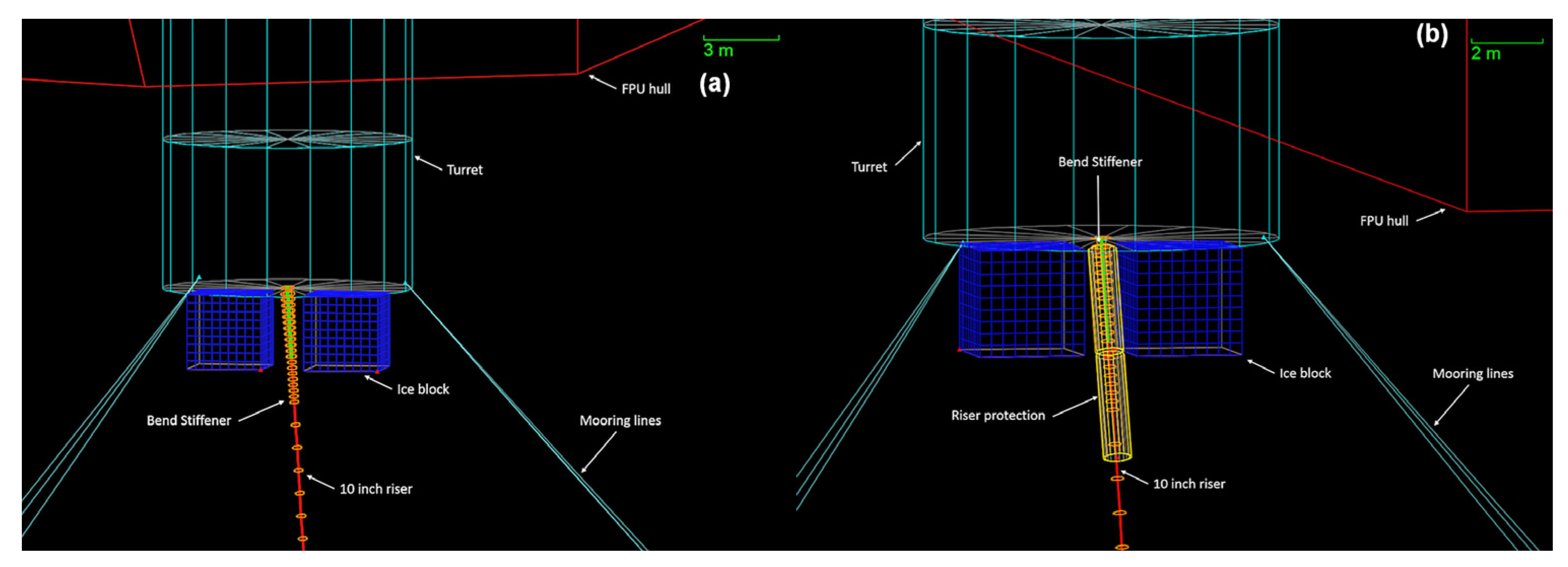
3.3. Effect of Floating Ice on Dynamic Performance of Risers

Adding floating ice to the model reduces the MBR model from 5 m to 1.5 m, which is lower than the allowed limits for the riser cross-section. Bending moment was also found to increase, along with other tension values. The only exception was the tension at TDP, which reduced from 72 kN to 25 kN. However, it is worth noting that the tether tension decreased to zero values, showing its broken state and that it was no longer supporting the riser. The results presented in Table 9 show that the value from the MBR and bending moment exceeds the limits of the riser cross-section.

3.4. Effect of Floating Ice on Dynamic Performance of Armour Protected Risers

As presented in Table 10, the values of the MBR and the bending moment of the riser exceed the limits of the riser cross-section. The riser parameters with ice and riser protection included in the model for the same environmental conditions as in the previous cases stay within the allowable limits of the riser cross-section, but the bending moment is still relatively high, as the armour transmits some portion of the ice impact energy to the riser.

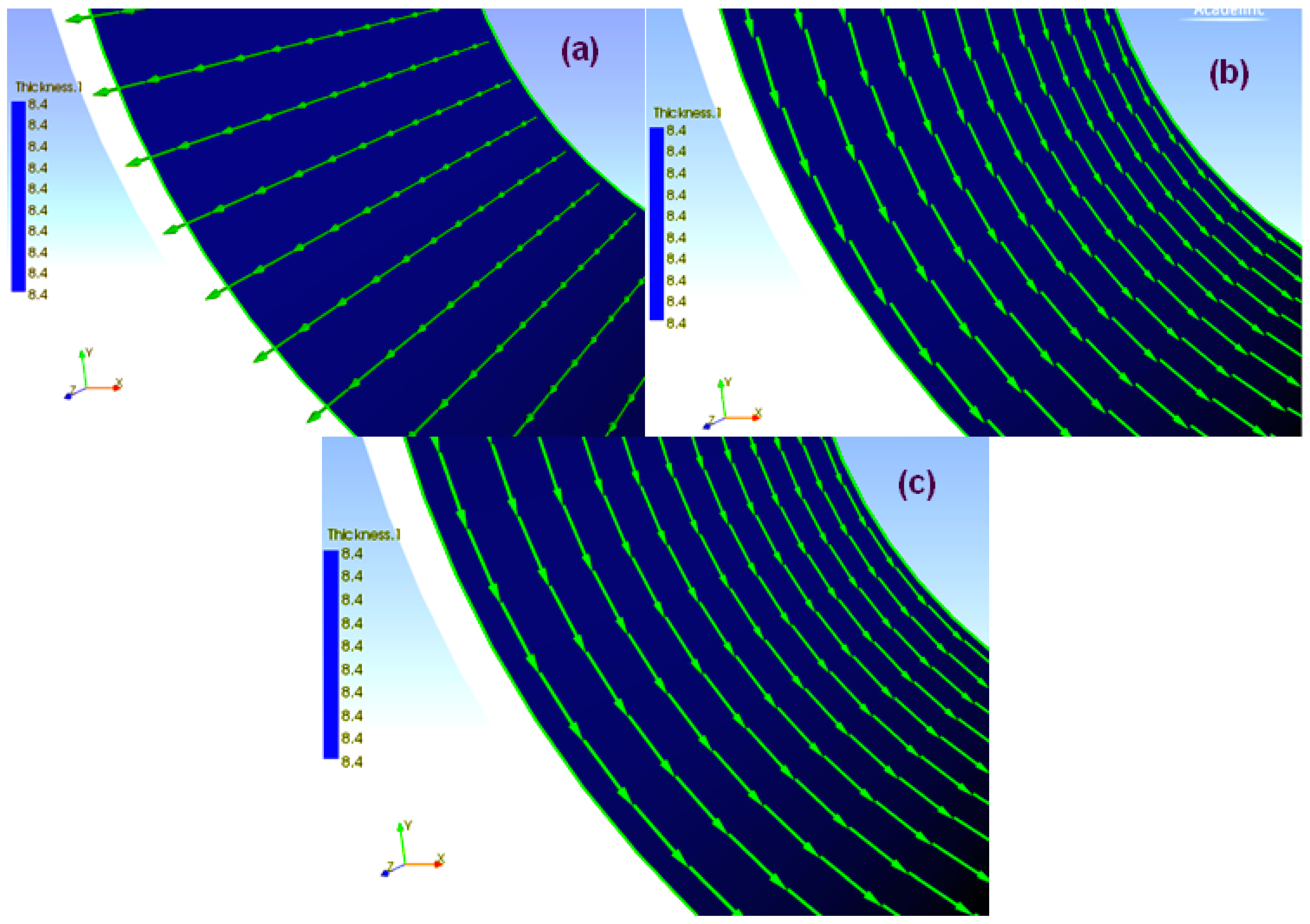
3.5. Local Model Results

The most conservative loads derived from the global dynamic analysis were applied to the local Ansys model to evaluate the hoop stresses. The combined loads of pressure, axial and bending were applied to the local model to find out the microcracking failure according to Puck’s criterion. The results are presented and discussed in the subsequent sections.

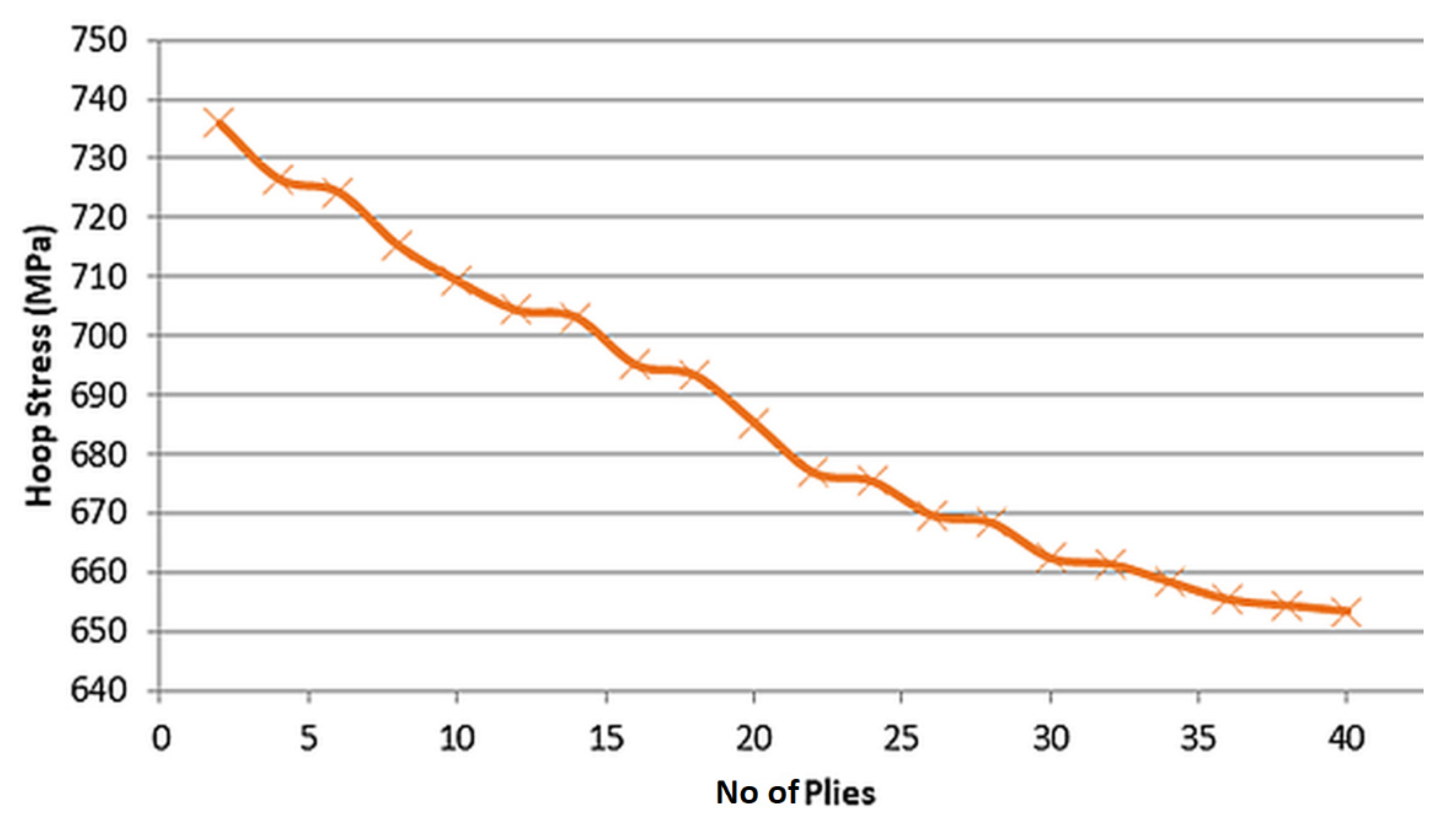
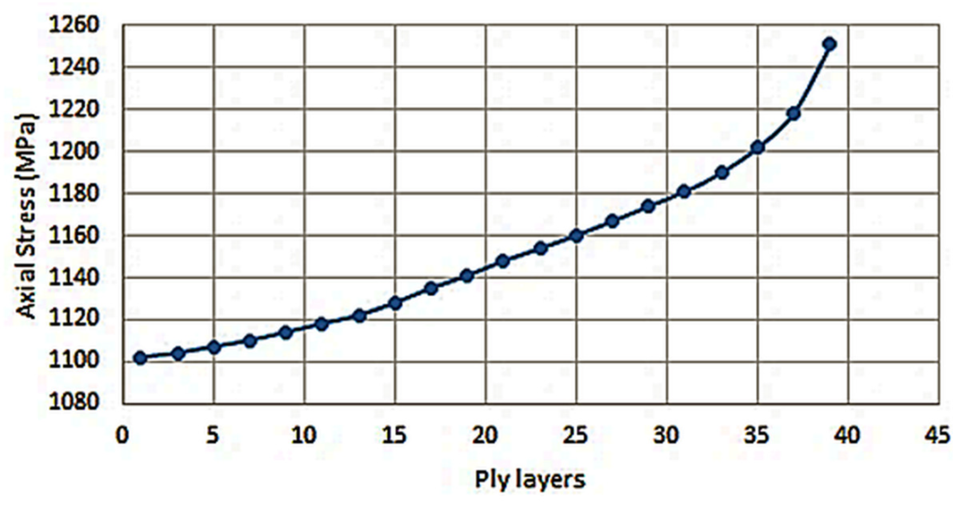
3.5.1. Pressure Load—Burst

The composite riser will undergo both internal and external pressure. The stress will be evaluated in each layer, mainly looking at the +88 pressure plies that will take the majority of the internal design pressure, 5000 psi. As seen in Figure 8, the stress is highest on the inner layer and decreases towards the outer diameter. The 88 and −88 plies experienced the majority of stress. The highest stress is seen in layer 2 with 736 MPa, 50.44% of the allowable stress. However, they were still considered in Puck’s failure criterion; when the value of the Puck is 1 or greater, failure occurs. It was found [39] that just carrying out maximum stress theory was not enough to identify the failure. The Puck’s failure criterion showed failure in layer 2 where the stress was highest. The initial failure mode being detected is pMA; this means Puck’s criterion found that matrix failure due to tension will occur first. The Max Hoop Stress was then compared with theory, using Lamé equations and those based on material properties, showing a difference of 5.486% and thus validating the ANSYS model that was being used.

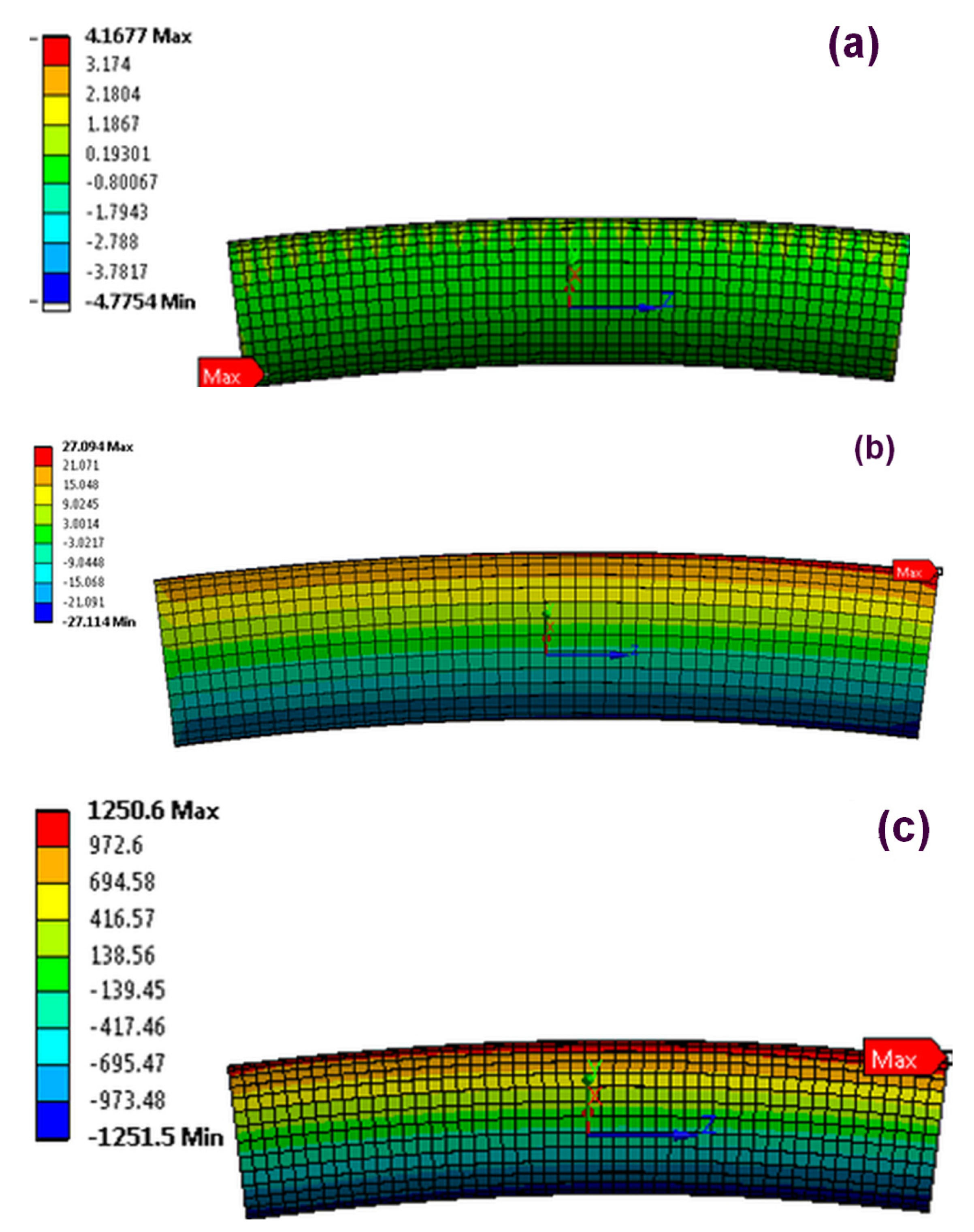
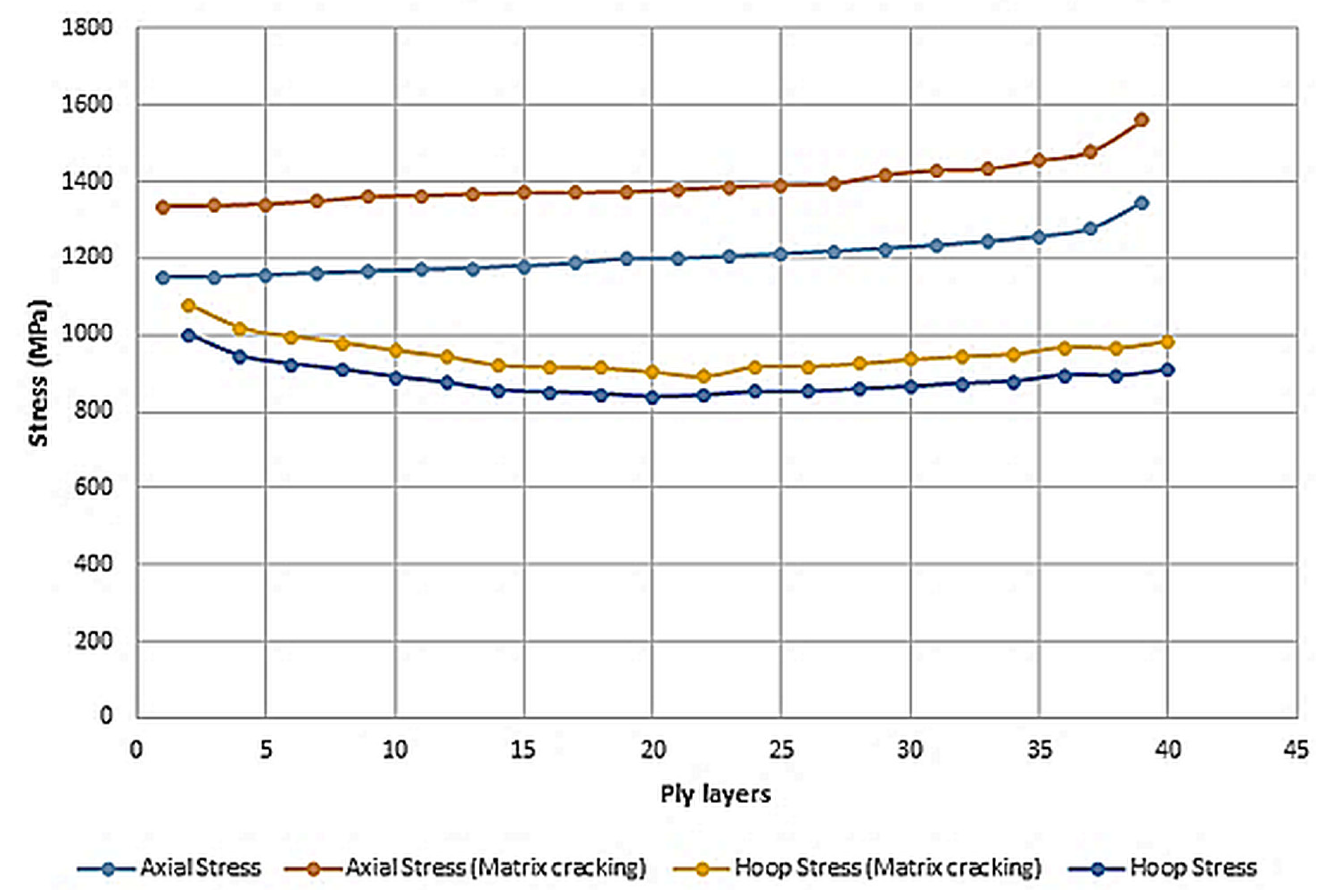
3.5.2. Bending Moments

The bending moments experienced by the full riser was simulated using OrcaFlex in the global section and is displayed in Figure 9. The axial stress in layer 39 (±88 ply layers) reaches 1250.1 MPa.

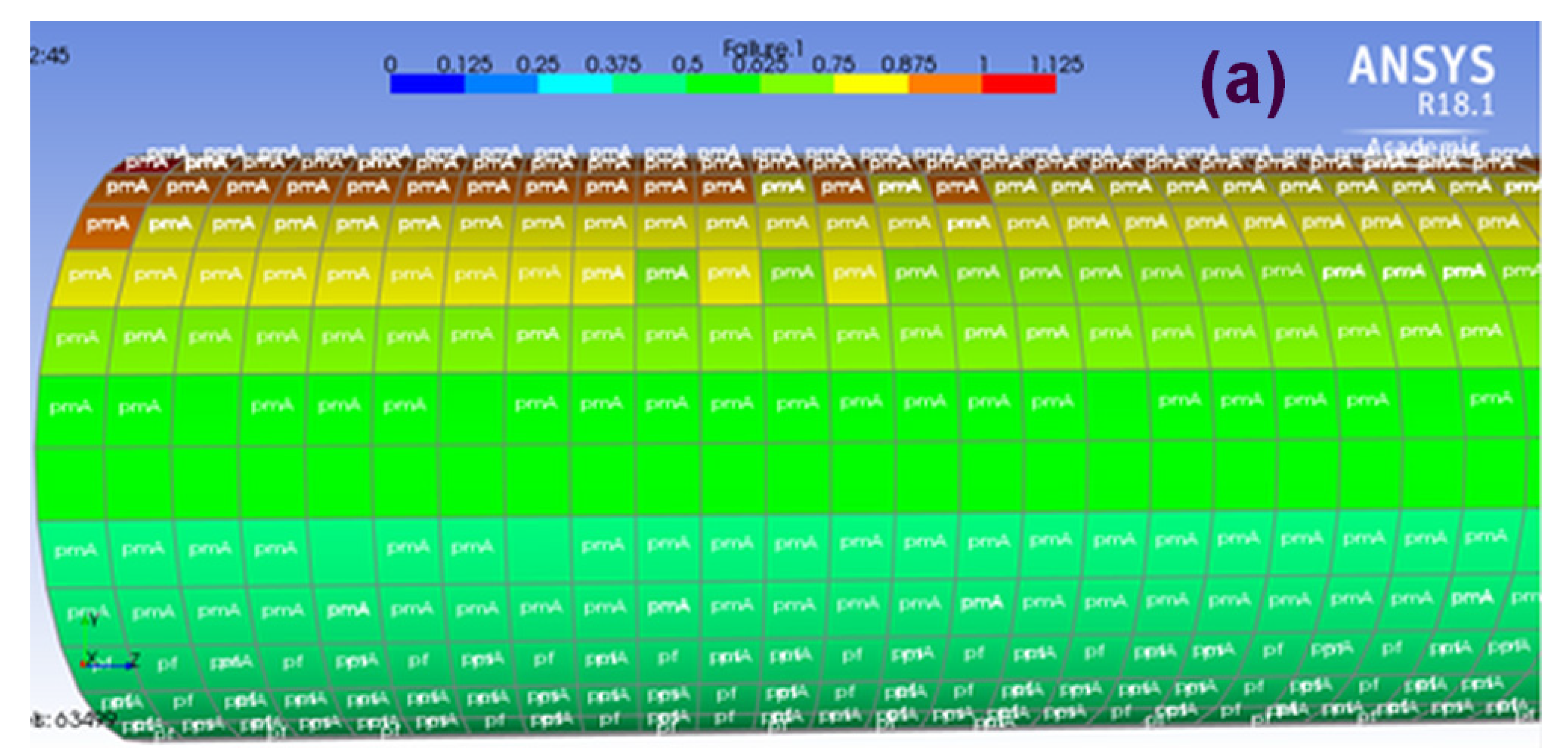
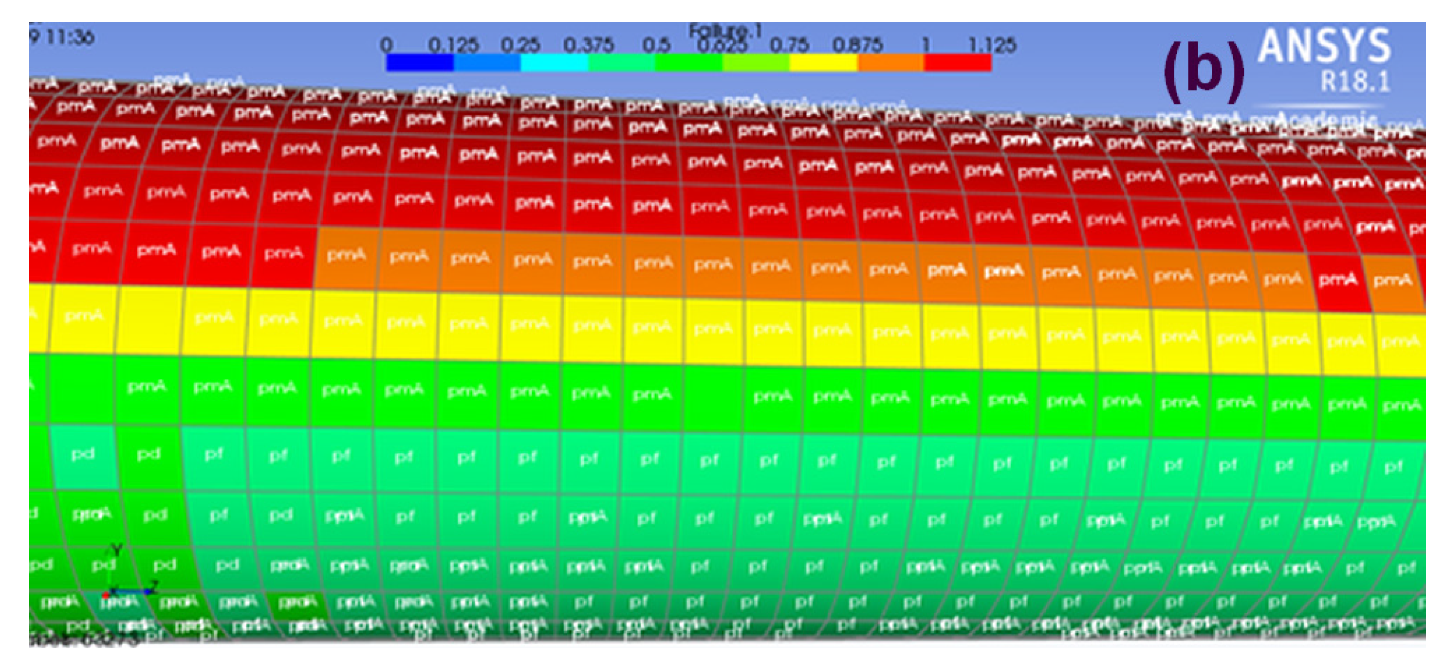
3.5.3. Failure according to Puck Modified Criterion

The worst case was taken from the global analysis and then fed into ANSYS along with an internal pressure of 34.47 MPa (5000 Psi). The maximum tension was found to be 850 kN in the worst-case scenario, as mentioned in the dynamic analysis. It is worth noting that the tension share of the composite layer came to 42.15 kN. Applying all of the stresses allowed estimation of the major stresses at the lamina level. Using displacement control, the bending radius was increased from 10 m to 6.5 m, or until one or more laminae did not fail under modified Puck’s criterion. Under bending moments, pressure loading, and axial tension, the main stresses of interest for layers with different fibre angles are shown in Figure 10.
The maximum hoop and axial stress in layers with 88° correspond to the lagend showing matrix cracking, while term axial and hoop stress refers to maximum stress in layers with a 0° matrix. Due to the bending of the section of the CFRP pipe, the stress increased towards the outer edge. The internal pressure was more dominant for the hoop stress and could be seen to decrease in a linear manner as it moved towards the outer edge. In terms of hoop stress, the range falls between 840–999 MPa, with layer 2 exhibiting the highest value. On the other hand, the axial stress range was identified to be between 1344 to 1562 MPa, with the maximum value being recorded in layer 39. Figure 11 identifies the failure mechanisms with the combined loading; a plot showing the failure of the lamina is zoomed in to demonstrate the matrix failure predicted for a few elements along the top surface after the bending moment was applied to the model, achieving a bending radius of 8 m. The bottom mesh element at the bottom section of the pipe was about to fail but was still far from ultimate failure.
To highlight the effects of bending in layers designed for withstanding hoop stresses, the composite pipe model was run with Puck’s modified failure criterion. As a result of the bending of the pipe, all types of stresses seemed to increase for all values, as seen in Figure 12a,b. In comparison to the layers, where stresses are parallel to fibres, as seen in Figure 12a, it does not fail. As seen in Figure 12a, most of the load is carried by fibres and failure is low. A large increase in the axial stress was observed, leading to failure, as seen in Figure 12b. This demonstrates that bending can cause failure due to the increase in axial stress, which is perpendicular to the direction of the fibres. Moreover, it was also seen that the matrix failure can be observed even at a large bending radius. The minimum suggested bending radius did not meet the criterion for matrix cracking, which could lead to further ultimate damage.

4. Conclusions and Recommendations

(1)
A static analysis for the six most popular flexible riser global configurations was performed and the pliant wave global configuration was selected for further dynamic analysis based on the conservative value for MBR. The dynamic extreme analysis was performed for the normal operations as well as for the accidental state with one mooring line broken. Using worst-case scenario moment, tension, and bending, the local microscale model was created using Ansys®. The key conclusions are presented below.
(2)
The dynamic extreme analysis showed that the designed cross-sectional configuration of the riser maintained the integrity of the system under the extreme environmental conditions of the Arctic. The result of the dynamic analysis with floating ice showed that most of the riser’s critical parameters exceeded the maximum allowable limits for this riser. It may be concluded that the flexible risers would require additional measures for mitigating the effect of the floating ice. The riser armour system may be used to as an option to mitigate the effects of the floating ice on the riser system and drive the riser’s parameters within the just allowable limits.
(3)
The micro-scale analysis of the composite riser showed that the riser pressure armour would not fail at a 10 m bending radius, which is far less than recommended. Moreover, microcracks will appear in layers with 88° fibre angles at a low bending radius and strain limit than the recommended value of 3.6 m. The layer to absorb the axial stresses should be incorporated to mitigate the low local bending radius due ice floe interaction. In the arctic sea, all risers are recommended to be protected with armour to protect them from the impact of the ice. There are two options for mitigating the effect of the harsh environment of the Arctic:
(a)
The turret of the FPU can be submerged deep enough to eliminate the possible coalition of the riser with floating ice. This option can guarantee the integrity of the hybrid riser system to a certain extent. This method has already been used under extreme sea conditions; however, it may be possible that some ice floes can still collide with the riser. At the same time, the extension of the turret will heavily increase the cost of the installation and influence the FPU design.
(b)
The riser armour protection can be utilised to minimise the effect of the ice-riser interaction and reduce the cost of the system, but the bending moment of the hybrid riser may remain high. It may be possible that the armour along the few metres of the arclength of hybrid riser cannot guarantee the total protection of the riser.
(4)
To reduce the drag effect of the major part of the flowing ice in normal sea state conditions, the extended turret system can be used but in a shorter time window. Concurrently, the riser armour can be used, minimising the effect of the ice in extreme environmental conditions. Finally, such a configuration will help reduce the cost of the turret system and FPU, and will guarantee the riser system’s integrity in normal and extreme environmental conditions.
(5)
The effect of environmental loading can be eliminated by using subsea production facilities. The feasibility of using such technology can be analysed for arctic field with technical and economic considerations.

Supplementary Materials

The following supporting information can be downloaded at: https://www.mdpi.com/article/10.3390/jcs7060212/s1.

Author Contributions

D.K. created, analysed all data and wrote a manuscript. K.P. supervision, concept generation, review of manuscript and help with analysis. S.K.N. reviewed manuscript and made changes, formatting, and overview. All authors have read and agreed to the published version of the manuscript.

Funding

Support for study—Robert Gordon University.

Data Availability Statement

Selective data can be provided on request.

Conflicts of Interest

The authors declare no conflict of interest.

References

  1. Eik, K.; Gudmestad, O.T. Iceberg Management and Impact on Design of Offshore Structures. Cold Reg. Sci. Technol. 2010, 63, 15–28. [Google Scholar] [CrossRef]
  2. ISO 19906:2019; Petroleum and Natural Gas Industries—Arctic Offshore Structures. ISO: Geneva, Switzerland, 2019. Available online: https://www.iso.org/standard/65477.html (accessed on 11 February 2023).
  3. Boateng, J.A.; Diawuo, F.A. Design and Hydrodynamic Loading Analysis of Production Riser for the Arctic. Int. J. Pet. Eng. 2015, 1, 221. [Google Scholar] [CrossRef]
  4. Nammi, S.K.; Gupta, R.; Pancholi, K. Comparative Strength and Stability Analysis of Conventional and Lighter Composite Flexible Risers in Ultra-Deep Water Subsea Environment. Proc. Inst. Mech. Eng. Part E J. Process Mech. Eng. 2022, 09544089221144394. [Google Scholar] [CrossRef]
  5. Dodds, N.; Pancholi, K.; Jha, V.; Tariq, S.F.; Latto, J. In Situ Investigation of Microstructural Changes in Thermoplastic Composite Pipe Under Compressive Load. In Proceedings of the International Conference on Offshore Mechanics and Arctic Engineering-OMAE 2014, 6A, San Francisco, CA, USA, 8–13 June 2014. [Google Scholar] [CrossRef]
  6. Derisi, B.; Hoa, S.; Xu, D.; Hojjati, M.; Fews, R. Composite Tube Exhibiting Large Deformation under Bending. J. Compos. Mater. 2010, 44, 2005–2020. [Google Scholar] [CrossRef]
  7. Pancholi, K.; Jha, V.; Dodds, N.; Huo, D.; Latto, J. In Situ and Real Time X-Ray Computed Tomography for the Micromechanics Based Constitutive Modelling of the Unbonded Flexible Riser. In Proceedings of the International Conference on Offshore Mechanics and Arctic Engineering-OMAE 2015, 5A, St. John’s, NL, Canada, 31 May–5 June 2015. [Google Scholar] [CrossRef]
  8. Jha, V.; Latto, J.; Dodds, N.; Anderson, T.A.; Finch, D.; Vermilyea, M. Qualification of Flexible Fiber-Reinforced Pipe for 10,000-Foot Water Depths. In Proceedings of the Offshore Technology Conference, Houston, TX, USA, 6–9 May 2013. [Google Scholar] [CrossRef]
  9. Fiabane, J.; Prentice, P.; Pancholi, K. High Yielding Microbubble Production Method. Biomed Res. Int. 2016, 2016, 3572827. [Google Scholar] [CrossRef] [PubMed]
  10. Gupta, R.; Pancholi, K.; Prabhu, R.; Pancholi, M.; Huo, D.; Jha, V.; Latto, J. Integrated Self-Healing of the Composite Offshore Structures. In Proceedings of the OCEANS 2017-Aberdeen, Aberdeen, UK, 19–22 June 2017; pp. 1–4. [Google Scholar] [CrossRef]
  11. Gupta, R.; Dehong, H.; Maggie, W.; Vineet, J.; Gavin, B.G.S.; Ketan, P. Novel method of healing the fibre reinforced thermoplastic composite: A potential model for offshore applications. Compos. Commun. 2019, 16, 67–78. [Google Scholar] [CrossRef]
  12. Allen, S.; Kassner, C. Global Analysis of the Terra Nova Riser System. In Proceedings of the Offshore Technology Conference, Houston, TX, USA, 30 April–3 May 2001. [Google Scholar] [CrossRef]
  13. Allen, S. 10 Years of Sub Arctic Subsea Projects-Stepping Stones for Arctic Development. Soc. Pet. Eng. Arct. Technol. Conf. 2011, 2, 696–705. [Google Scholar] [CrossRef]
  14. Hwang, J.K.; Bang, G.J.; Roh, M.I.; Lee, K.Y. Detailed Design and Construction of the Hull of an FPSO (Floating, Production, Storage, And Off-loading Unit). In Proceedings of the Nineteenth International Offshore and Polar Engineering Conference, Osaka, Japan, 21–26 July 2009. [Google Scholar]
  15. Edmond, C.; Liferov, P.; Metge, M. Ice and Iceberg Management Plans for Shtokman Field. Soc. Pet. Eng. Arct. Technol. Conf. 2011, 2, 600–608. [Google Scholar] [CrossRef]
  16. Kai-Tung, M.; Luo, Y.; Kwan, C.-T.T.; Wu, Y. Mooring System Engineering for Offshore Structures; Gulf Professional Publishing: Houston, TX, USA, 2019. [Google Scholar]
  17. Karlinsky, S.L.; Chernetsov, V.A. Floating Production Unit Resistance to Iceberg Impact. OnePetro, 20 June 2010. Available online: https://onepetro.org/ISOPEIOPEC/proceedings-abstract/ISOPE10/All-ISOPE10/ISOPE-I-10-377/11475 (accessed on 11 February 2023).
  18. Gabet, C.; Chicheportiche, S.; Vivet, R.; Taravel-Condat, C. Small and Full Scale Testing of Flexible Pipes in Cold Environment for Arctic Use. Soc. Pet. Eng. Arct. Technol. Conf. 2011, 1, 436–444. [Google Scholar] [CrossRef]
  19. Challenges with Ice-Related Design and Operating Philosophy of the Shtokman Floating Production Unit. Available online: https://www.elibrary.ru/item.asp?id=23965637 (accessed on 11 February 2023).
  20. Bonnemaire, B. Response of an Armoured Riser to Wave and Ice Actions And to Impacts From Ice Blocks. Int. J. Offshore Polar Eng. 2005, 15. [Google Scholar]
  21. Gupta, R.; Badel, B.; Gupta, P.; Bucknall, D.; Flynn, D.; Pancholi, K. Flexible Low-Density Polyethylene–BaTiO3 Nanoparticle Composites for Monitoring Leakage Current in High-Tension Equipment. ACS Appl. Nano Mater. 2021, 4, 2413–2422. [Google Scholar] [CrossRef]
  22. Gupta, R.; Smith, L.; Njuguna, J.; Deighton, A.; Pancholi, K. Insulating MgO-Al2O3-LDPE Nanocomposites for Offshore Medium-Voltage DC Cables. ACS Appl. Electron. Mater. 2020, 2, 1880–1891. [Google Scholar] [CrossRef]
  23. Kumbhare, N.; Moheimani, R.; Dalir, H. Analysis of composite structures in curing process for shape deformations and shear stress: Basis for advanced optimization. J. Compos. Sci. 2012, 5, 63. [Google Scholar] [CrossRef]
  24. Talreja, R. Assessment of the Fundamentals of Failure Theories for Composite Materials. Compos. Sci. Technol. 2014, 105, 190–201. [Google Scholar] [CrossRef]
  25. Tang, W.; Blanche, J.; Mitchell, D.; Harper, S.; Flynn, D. Characterisation of Composite Materials for Wind Turbines Using Frequency Modulated Continuous Wave Sensing. J. Compos. Sci. 2023, 7, 75. [Google Scholar] [CrossRef]
  26. Gupta, R.; Mitchell, D.; Blanche, J.; Harper, S.; Tang, W.; Pancholi, K.; Baines, L.; Bucknall, D.G.; Flynn, D. A Review of Sensing Technologies for Non-Destructive Evaluation of Structural Composite Materials. J. Compos. Sci. 2021, 5, 319. [Google Scholar] [CrossRef]
  27. Adams, D.F.; Doner, D.R. Transverse Normal Loading of a Unidirectional Composite. J. Compos. Mater. 1967, 1, 152–164. [Google Scholar] [CrossRef]
  28. Amaechi, C.V.; Chesterton, C.; Butler, H.O.; Gillet, N.; Wang, C.; Ja’e, I.A.; Reda, A.; Odijie, A.C. Review of composite marine risers for deep-water applications: Design, development and mechanics. J. Compos. Sci. 2022, 6, 96. [Google Scholar] [CrossRef]
  29. Fergestad, D.; Løtveit, S.A.; Leira, B.J. Life-Cycle Assessment of Flexible Risers. In Proceedings of the International Conference on Offshore Mechanics and Arctic Engineering-OMAE 2014, 6B, San Francisco, CA, USA, 8–13 June 2014. [Google Scholar] [CrossRef]
  30. Schäkel, M.; Hosseini, S.A.; Janssen, H.; Baran, I.; Brecher, C. Temperature analysis for the laser-assisted tape winding process of multi-layered composite pipes. Procedia CIRP 2019, 85, 171–176. [Google Scholar] [CrossRef]
  31. Distributed Buoyancy Module-AIS. Available online: https://www.aisltd.com/product/c-float/bardot-distributed-buoyancy-module/ (accessed on 11 February 2023).
  32. Sævik, S. A Finite Element Model for Predicting Stresses and Slip in Flexible Pipe Armouring Tendons. Comput. Struct. 1993, 46, 219–230. [Google Scholar] [CrossRef]
  33. Drawshi, M.; Cederbaum, G. Stability of Multiloaded Viscoelastic Nonlinear Beams. Comput. Struct. 1993, 46, 215–218. [Google Scholar] [CrossRef]
  34. Zhang, H.; Tong, L.; Addo, M.A. Mechanical Analysis of Flexible Riser with Carbon Fiber Composite Tension Armor. J. Compos. Sci. 2020, 5, 3. [Google Scholar] [CrossRef]
  35. API|API Recommended Practice 2D, 7th ed. Available online: https://www.api.org/products-and-services/standards/important-standards-announcements/spec2d (accessed on 11 February 2023).
  36. DNV-ST-F201 Riser Systems-DNV. Available online: https://www.dnv.com/oilgas/download/dnv-st-f201-riser-systems.html (accessed on 11 February 2023).
  37. Amaechi, C.V.; Gillett, N.; Odijie, A.C.; Hou, X.; Ye, J. Composite Risers for Deep Waters Using a Numerical Modelling Approach. Compos. Struct. 2019, 210, 486–499. [Google Scholar] [CrossRef]
  38. Bai, Y.; Lu, Y.; Cheng, P. Analytical Prediction of Umbilical Behavior under Combined Tension and Internal Pressure. Ocean. Eng. 2015, 109, 135–144. [Google Scholar] [CrossRef]
  39. Bhavya, S. Failure Analysis of a Composite Cylinder. IOSR J. Mech. Civ. Eng. 2012, 3, 1–7. [Google Scholar] [CrossRef]
Figure 1. (a) Submerged turret system (b,c) disconnetable turret system [16].
Jcs 07 00212 g001
Figure 3. FPU Mean, near and far offsets.
Jcs 07 00212 g003
Figure 4. The flexible riser configurations used for static analysis. From top left to bottom right (a) Catenary (b) lazy wave (c) pliant wave (d) steep wave (e) lazy S (f) steep S flexible riser configuration analysed.
Jcs 07 00212 g004
Figure 5. Flexible riser system with (a) the floating ice included and (b) floating ice with armour protection.
Jcs 07 00212 g005
Figure 6. Ply layers: (a) 0-ply (b) 88-ply and (c) -88-ply.
Jcs 07 00212 g006
Figure 7. Schematic illustration of the combined loading scenario for the CFRP pressure armour pipe of the hybrid flexible riser. The pipe is subjected to a combination of bending, axial, internal and external pressure, representing actual operating conditions. The yellow arrows indicate the direction of the bending loads, while the red arrows represent the axial and pressure load. The arrows at location A to F shows the loading direction. B and F presents applied moments E and A (hidden on opposite side) represents axial tension.
Jcs 07 00212 g007
Figure 8. Hoop stress through the layers.
Jcs 07 00212 g008
Figure 9. Axial Stress through the thickness.
Jcs 07 00212 g009
Figure 10. Layer 39 stress distribution (a) Radial (b) Hoop & (c) Axial.
Jcs 07 00212 g010
Figure 11. Effect of fibre orientation in layer on maximum stress value estimated at each lamina of unidirectional tape in CFRP pipe in flexible riser subject to combined axial, bending and internal pressure. Matrix cracking was observed at 8 m radius in layer with 88° fibre angle where lower stresses and no matrix cracking was observed in layers with 0° fibre angle.
Jcs 07 00212 g011
Figure 12. Failure of the Lamina under Combined Loading. (a) shows the lamina under combined loading but with no visible failure at 9 m bending radius, while (b) shows the topmost layer of the composite pipe, which has experienced failure due to the same loading conditions but 8 m bending radius. The failure of the topmost layer in (b) highlights the critical role played by the axial strain by the bending moment in withstanding combined loading.
Jcs 07 00212 g012aJcs 07 00212 g012b
Table 1. Vessel offsets.
Mooring ConditionFPU Offset
(% of Water Depth)
FPU Offset (m)
Operational1034
Accidental1241
Table 2. Static analysis matrix showing all load cases considered.
Load CaseLimit StateInternal FluidFPU OffsetCurrent
1ULSEmptyMeanNone
2ULSEmptyFar180°
3ULSEmptyNear
4ULSEmptyCross90°
5ULSOperatingMeanNone
6ULSOperatingFar180°
7ULSOperatingNear
8ULSOperatingCross90°
9ULSFloodedMeanNone
10ULSFloodedFar180°
11ULSFloodedNear
12ULSFloodedCross90°
13ALSEmptyMeanNone
14ALSEmptyFar180°
15ALSEmptyNear
16ALSEmptyCross90°
17ALSOperatingMeanNone
18ALSOperatingFar180°
19ALSOperatingNear
20ALSOperatingCross90°
21ALSFloodedMeanNone
22ALSFloodedFar180°
23ALSFloodedNear
24ALSFloodedCross90°
Table 3. All flexible riser configurations for static analysis with their key feature dimensions.
CatenaryLazy WavePliant WaveSteep WaveLazy SSteep S
Total riser length828 m828 m828 m828 m828 m828 m
Upper section358 m320 m320 m518 m438 m588 m
Lower section470 m (from TDP to PLET)308 m (from TDP to PLET)308 m (from TDP to PLET)110 m350 m240 m
Hung off angle11°13°19°25°27°
Upper termination point(1) turret centre, 22 m below MSLSame as (1)Same as (1)Same as (1)Same as (1)Same as (1)
Buoyant section 200 m200 m200 m
Arc length to the tether clump -634 m
Horizontal displacement from the turret to the tether anchor -401 m
Tether length -40 m
Table 4. Dynamic analysis load matrix.
Load CaseLimit StateInternal FluidFPU OffsetCurrentWaveWind
1ULSEmptyFar180°180°180°
2ULSEmptyNear
3ULSEmptyCross90°90°90°
4ULSOperationFar180°180°180°
5ULSOperationNear
6ULSOperationCross90°90°90°
7ULSFloodedFar180°180°180°
8ULSFloodedNear
9ULSFloodedCross90°90°90°
10ALSEmptyFar180°180°180°
11ALSEmptyNear
12ALSEmptyCross90°90°90°
13ALSOperationFar180°180°180°
14ALSOperationNear
15ALSOperationCross90°90°90°
16ALSFloodedFar180°180°180°
17ALSFloodedNear
18ALSFloodedCross90°90°90°
Table 5. Composite dimensions.
Parameters
Pressure armour ID(8 in)
Pressure armour OD(8.8588 in)
Ply thickness0.21 mm (0.008267717 in)
Ply stack-up[0, 88, 0, −88]
Stack ups10 (40 layers in total)
Table 6. CFRP coupled PA-12 properties (ANSYS).
Orthotropic Materials—CFRP
Young’s Modulus X direction 1.44 × 10 11 Pa
Young’s Modulus Y direction 9.18 × 10 9 Pa
Young’s Modulus Z direction 9.18 × 10 9 Pa
Poisson’s Ratio XY0.33
Poisson’s Ratio YZ0.03
Poisson’s Ratio XZ0.33
Shear Modulus XY 4.11 × 10 9 Pa
Shear Modulus YZ 3.439 × 10 9 Pa
Shear Modulus XZ 4.11 × 10 9 Pa
Stress Limits—Tensile X direction1632 MPa
Stress Limits—Tensile Y direction34 MPa
Stress Limits—Tensile Z direction34 MPa
Table 7. Most conservative results obtained after static analysis of all load cases.
Riser ConfigurationRiser Minimum
Bending
Radius (m)
Riser Effective Tension at Turret (kN)Riser Effective Tension at PLET (kN)Riser Bending Moment at Turret (kN·m)Riser Bending Moment at PLET (kN·m)Riser Effective Tension at TDP
(kN)
Catenary192862.26.7022
Lazy Wave61694125042
Pliant Wave132173511046
Steep wave6303638923.8-
Lazy S12436559061
Steep S55142563.523.3-
Table 8. Summary of the evaluated parameters.
MBR
(m)
Bending Moment (kN·m)Turret
Max Tension
(kN)
PLET Max Tension
(kN)
TDP Min
Tension
(kN)
Tether Max
Tension
(kN)
Dynamic simulation (ALS/flooded/fat)524467967290
Riser limits3.633500050005000-
Table 9. Dynamic simulation results of the riser system with floating ice included in the model.
MBR
(m)
Bending Moment (kN·m)Turret
Max Tension
(kN)
PLET Max Tension
(kN)
TDP Min
Tension
(kN)
Tether Max
Tension
(kN)
Dynamic simulation (ALS/flooded/fat)1.587850390250
Riser limits3.633500050005000-
Table 10. Dynamic simulation results of the riser system with floating ice and riser armour protection included in the model.
MBR
(m)
Bending Moment (kN·m)Turret
Max Tension
(kN)
PLET Max Tension
(kN)
TDP Min
Tension
(kN)
Tether Max
Tension
(kN)
Dynamic simulation (ALS/flooded/fat)4.526520967290
Riser limits3.533270027002700-
Disclaimer/Publisher’s Note: The statements, opinions and data contained in all publications are solely those of the individual author(s) and contributor(s) and not of MDPI and/or the editor(s). MDPI and/or the editor(s) disclaim responsibility for any injury to people or property resulting from any ideas, methods, instructions or products referred to in the content.

