1. Introduction
With the development of electronic technologies and increasing uses of electronic devices, the exposure to electromagnetic (EM)-field radiations has widely increased [
1,
2]. Moreover, lightning strike damages are becoming a major concern; thus, multifunctional structural composites are required to act as an EMI shield for avionic equipment, such as flight recorders, navigation units, and flight-control systems [
1,
2]. This results in an increased need for electromagnetic shielding and shielding materials capable of blocking the EM waves [
3]. These materials are characterized by excellent electrical conductivity and electromagnetic properties. To date, this function is mainly performed by metals, but their use could be limited due to their weight and their susceptibility to corrosion. To overcome these drawbacks, researchers investigated the possibility of using carbon-fiber composites as shielding materials. A shielding effectiveness (SE) of ~62 dB has been found by Ramadin et al. [
4] for a laminated epoxy composite of 30 mm specimen at 9 GHz. Nanocomposites with improved shielding capability can be fabricated by using carbonaceous nanofillers as reinforcement [
5,
6]. Specifically, bidimensional lamellar nanoparticles, such as graphene, are optimal candidates thanks to their high thermal and electrical conductivities and intrinsic barrier properties [
7,
8]. Graphene also possesses wave absorption capabilities and could have good reflecting properties with unique electrical and mechanical features. Nevertheless, the main challenge is to reproduce on the macroscale the mechanical and functional properties of this nanometric reinforcement. To do this, special architectures can be considered, mimicking existing materials, such as nacre [
9]. Thanks to its particular brick and mortar (B&M) architecture, constituted by a high quantity of stiff but brittle nanoparticles bonded together by a small amount of soft but tough phase (<5 vol%), this material exhibits excellent performance. The oriented nanoplatelets form a conductive path along the in-plane direction, resulting in a higher in-plane conductivity rather than out-of-plane conductivity [
10,
11,
12]. Composites with brick-and-mortar architecture work as efficient EMI shielding, being the ideal candidate for these applications. Compared to metals, they are characterized by low weight, excellent electrical conductivity, high thermal stability, and anticorrosion properties [
7].
A quantitative measure of EM shielding is the shielding effectiveness (SE), which is measured in decibels (dB) [
13]. Typical values of SE for many industrial applications are around 30 dB and provide an attenuation of EM waves of 99.9% [
14]. The EMI shielding ability is positively related to the electrical conductivity and thickness according to theoretical Simon’s formula. The electrical conductivity of the materials needs to be at least higher than 1 S/m to obtain excellent EMI shielding performance.
Various novel functional fillers with high electrical conductivity are extensively used to fabricate nanocomposites with excellent EMI shielding. Barani et al. [
15] investigated the SE of graphene/epoxy composites with 19.5 vol% filler. The material exhibits total shielding efficiency in the X-band frequency of 65 dB in the sample of 1 mm thickness. The same behavior was observed in GNP/PEI papers [
16], which exhibited good SE increasing with paper thickness. GNP composites also work as microwave absorbers in S-band for practical applications. Parida et al. [
17] investigated the SE of GNP/ethylene vinyl acetate (EVA)/ethylene-octene copolymer (EOC) blend composite in S-band and observed that, at 30 wt% of GNP loading, an SE of 67.63 dB was achieved mainly due to absorption mechanism. This is attributed to an increase in electrical conductivity that reaches 455 S/m, thanks to the formation of a conducting network within the insulating matrix. Good EMI shielding performances are also exhibited by flexible multi-layered MXene/thermoplastic polyurethane (TPU) films with brick-and-mortar architecture, prepared via a simple layer-by-layer spraying technique [
18]. Samples with 28.6 wt% MXene content and 52-µm thickness exhibit high electrical conductivity of 1600 S/m, excellent SE of 50.7 dB in the X-band, and outstanding specific shielding effectiveness of 7276 dB cm
2/g. In addition, the composite films have stable EMI shielding performance during continuous bending. Finally, Lai et al. [
19] investigated the SE of graphene oxide (GO) paper with porous architecture. These materials are able to block and absorb 99.99995% of the incident radiation, and exhibit an SE of 63.0 dB and a very high specific shielding effectiveness (SSE, namely SE divided by density and thickness) of 49,750 dB cm
2/g. Other works show that porous aerogels and sponges, thanks to the unique microstructures and excellent intrinsic properties, enable the scattering and trapping of EM waves [
20]. Hybrid nanocomposites are also fabricated with the intent of fabricating high-performance EMI shielding materials with the intent of improving the electrical conductivity [
21] or to combine the effect of dielectric and magnetic losses [
22].
In this work, the EMI shielding properties of GNP-based nanocomposites are investigated. The SE of different systems has been determined in order to assess the capacity of the material to attenuate the electromagnetic waves in the X-band. Two different configurations have been considered, compact and porous, varying the filler content and the thickness of the sample. In particular, four different systems have been tested with the waveguide measurement technique in the microwave band of the electromagnetic spectrum within 8–12 GHz: compact thin films (i), thick nanolaminates (ii), and thin (iii) and thick (iv) porous coatings. The morphology of the material has been assessed in order to determine the influence of nanostructure on the absorption capacity of the material.
2. Materials and Methods
Graphite nanoplatelets (GNP) with a lateral size of 30 μm and thickness of 14 nm (tradename G2nan were kindly supplied by NANESA, Arezzo, Italy) and epoxy resin HexFlow® RTM6 are employed to fabricate nanocomposites.
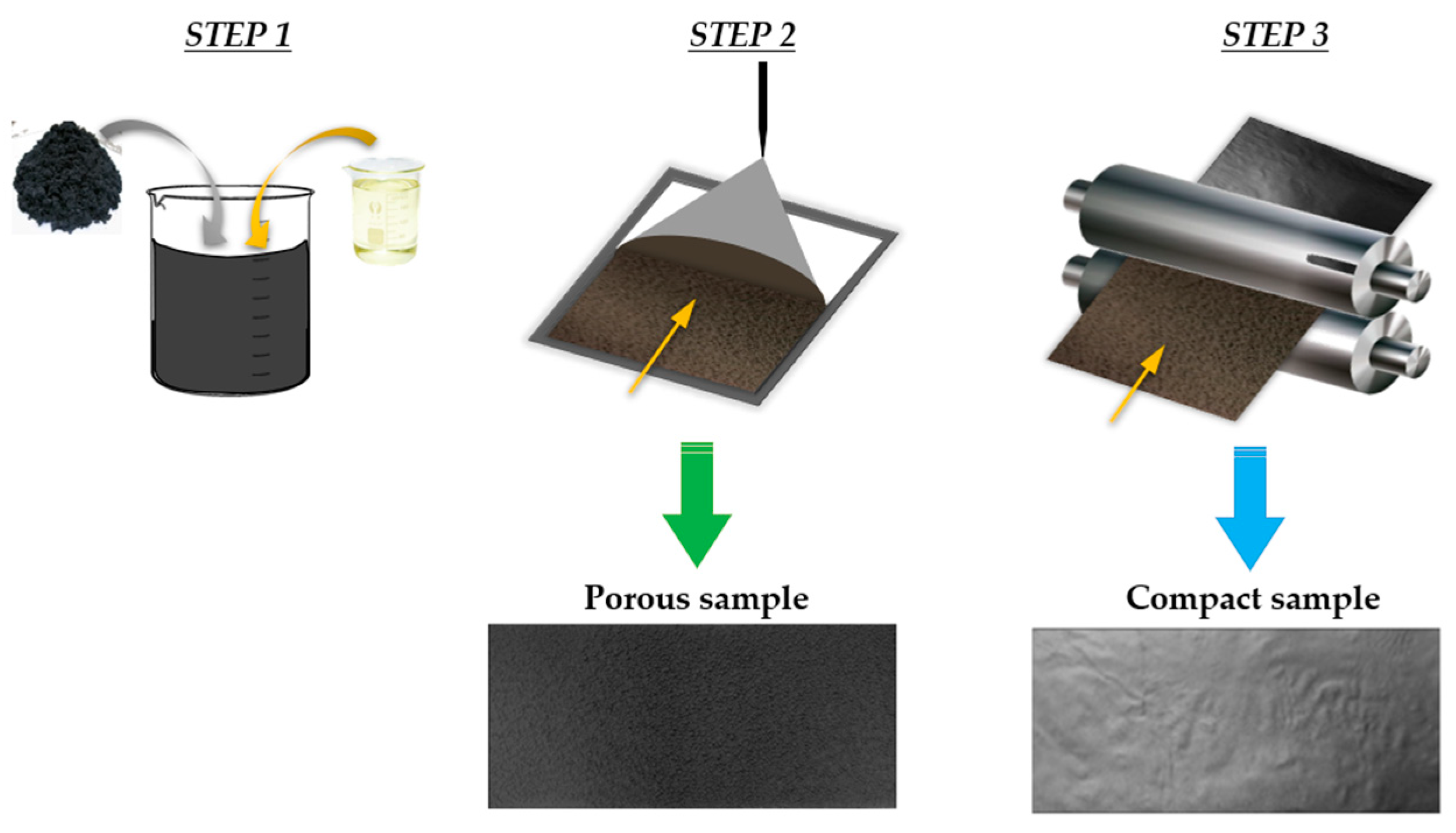
Porous and compact samples with different filler content and thickness have been fabricated following a top-down approach. The phases of the fabrication process are sketched in
Figure 1. GNPs are dispersed in acetone by ultra-sonication and mixed with a solution of epoxy diluted in acetone previously prepared (Step 1). The obtained paste is first deposited on a silicon non-sticky support using a semiautomatic tri-axes pantograph (Step 2). Then, the material is dried at room temperature all night to let the solvent evaporate. The result, at this stage, is a porous deposition. Porous coatings of different thicknesses and filler content have been fabricated.
Compact samples are produced by adding a calendaring step in the fabrication process (Step 3). The porous deposition of Step 2 is compacted, promoting particle orientation and reducing the thickness by about four times. The final pre-impregnated layer is obtained by pressing and curing the layer at increasing compaction pressure up to 10 bars [
23]. This process allows the production of flexible thin films with different filler content (from 10 to 90 wt%) [
23]. Since these films are impregnated with polymer, they can be assembled to fabricate thick laminates through a compression molding process, applying a pressure of 40–50 bar. Samples with different filler contents are manufactured at a nominal thickness of 1 mm (~20 stacked films).
The list of fabricated samples is reported in
Table 1.
Thermogravimetric analysis (TGA) (TA Instruments Q500, New Castle, DE, USA) is adopted to evaluate the real content of GNP in the samples. Measurements are performed in inert atmosphere, using nitrogen gas, with a temperature ramp of 10 °C/min from room temperature to 800 °C. The weight loss is evaluated at 600 °C, the temperature at which the percent residue from heating the pure resin is 10.3%. The morphology of the two architectures, porous and compact, has been investigated employing scanning electron microscopy (SEM) (FEI Quanta 200 FEG). Samples are fractured in nitrogen to have a picture of the internal cross-section.
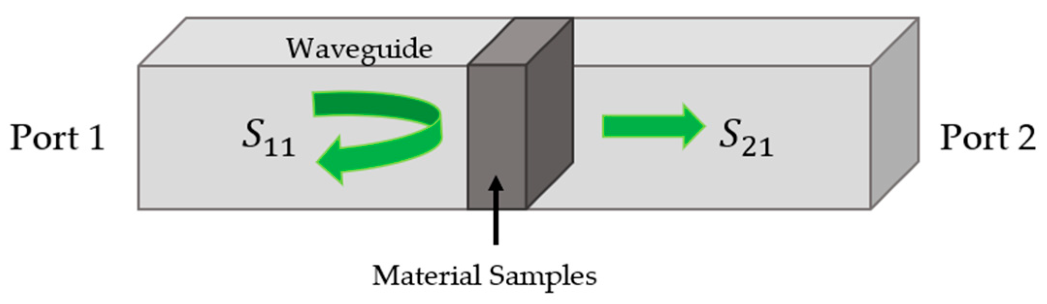
The shielding ability of the sample listed in
Table 1 is investigated, in the X-band, using a waveguide measurement setup. Rectangular samples of dimensions 22.86 mm × 10.16 mm are placed, filling the section of a WR-90 rectangular guide, and using the 37247C Anritsu Network Analyzer, and five measurements are collected for each sample (see
Figure 2). A standard Thru-Reflect Line (TRL) calibration has been performed to reduce the effects of the systematic errors [
24]. This is a calibration procedure, typically adopted when dealing with waveguides, introduced to overcome the problems associated with noncoaxial measurements. Indeed, a set of three distinct well-characterized impedance standards are often impossible to produce for noncoaxial transmission media, and this compromises the accuracy of the results when adopting a standard calibration method. This problem is solved, in the TRL calibration method, by adopting a formulation requiring very little knowledge about the standards. The calibration is performed in three steps: step 1 requires a thru connection, step 2 the use of unknown high reflective terminations, while step 3 requires the connection of a line of unknown length and propagation constant but known characteristic impedance. Due to the simplicity of the calibration standards, TRL can be easily applied in dispersive transmission media, such as microstrip, stripline, and waveguide.
The reflection, absorption, and transmission contributions are computed according to Equation (1) [
15]:
where
S11 and
S21 are the reflection and transmission coefficients in the sample, respectively (see
Figure 2).
The electrical resistance (
R) of the samples has been measured following the 4-probe technique at room temperature, as reported in [
25]. Strips of 1 cm × 10 cm have been mounted on a plastic frame and a current has been imposed by the DC power supply. The electrical resistivity (
r) and the electrical conductivity (
σ) have been computed, according to the following equation (Equation (2)):
The porosity of the material has been estimated as the variance of the measured density (
ρm) from the nominal density (
ρn) (Equation (3)):
The nominal density is computed according to the rule of mixture by taking into account the filler (2.20 g/cm3) and matrix (1.14 g/cm3) densities.
3. Results
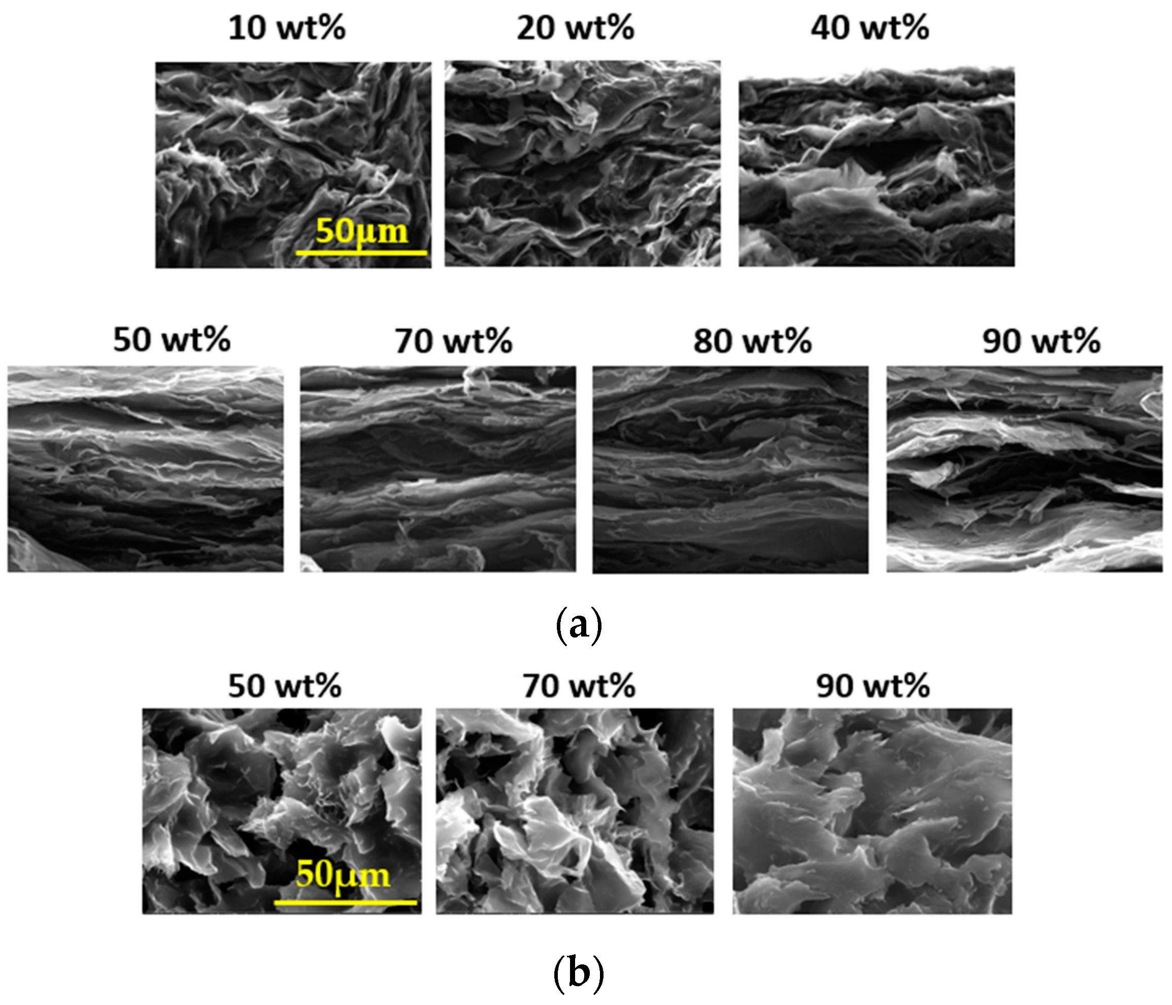
Figure 3a,b report SEM images of the cross-section (fractured surface) of porous and compact samples. By comparing the pictures, it is evident that the morphology significantly modifies when the calendaring process is added, passing from a chaotic to a well-aligned nano-architecture.
Moreover, by observing SEM images of compact samples (
Figure 3a), it appears that the nanostructure significantly modifies with increasing filler content. For samples with 10 and 20 wt% GNPs contents, the nanostructure is chaotic, while, for filler content greater than 50 wt%, the particles are highly oriented, with a laminated inner architecture and uniform texture. The nanoparticle geometry (i.e., high aspect ratio) combined with the processing technology ensure a good alignment in the plane at high filler content. However, samples with GNP content of 70 wt% show a more organized inner structure, with nanoplatelets leaned on the film plane. Above this critical content, the inner structure is threatened by dry spots and empty areas. This observation is corroborated by the porosity calculation, which increases with increasing filler content, being maximum at 90 wt% (
Table 2).
The compacting process significantly breaks down the porosity of the materials. In fact, at the same filler content, the porosity measured on samples (iii) and (iv) is in the order of 70–80% (
Table 3) compared to that of samples (i) and (ii), which are in the order of 25–30%.
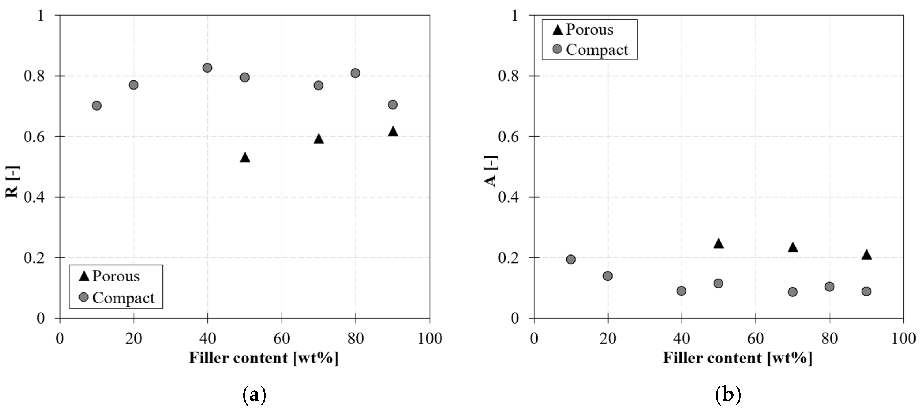
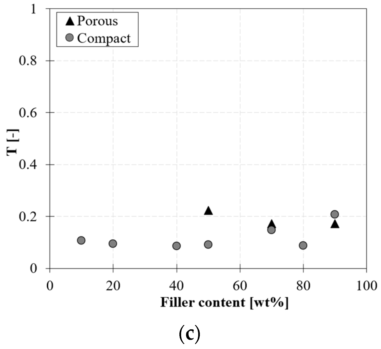
The results of the X-band waveguide measurements are reported in
Figure 4. A comparison limited only to the thin compact (i) and porous samples (iii) for different filler contents is reported.
Reflection, absorption, and transmission contributions are computed according to Equation (1) at 10 GHz.
The thin compact samples show a higher reflectivity with respect to the porous ones. The behavior is probably determined not only by the aligned arrangement of the nanoparticles, but also by the moderate–high values of the measured DC conductivity (σ), reported in
Table 4. However, this and further hypotheses can be definitively verified only after developing an electromagnetic model of the material. This point is currently under investigation. For a filler content greater than 40 wt%, the reflection coefficient is almost constant and equal to 80%.
Furthermore, higher values of absorption are obtained for low fractions of the filler content (20%@10 wt% and 14%@20 wt%), probably due to a more disordered nanostructure.
According to the observation above, it is expected that porous nanostructures (i.e., more chaotic structures) will exhibit a reduction in the reflection coefficient and an increased absorption of the EM waves. Indeed, in
Figure 4a, porous samples are still characterized by a significant reflectivity, albeit reduced with respect to the compact ones. For the samples with 50 wt%, a reduction of 30% is observed. On the other hand,
Figure 4b shows that porous samples exhibit an increased absorption capability with respect to the compact ones. For the samples with 50 wt%, absorption increases of about 130% are observed.
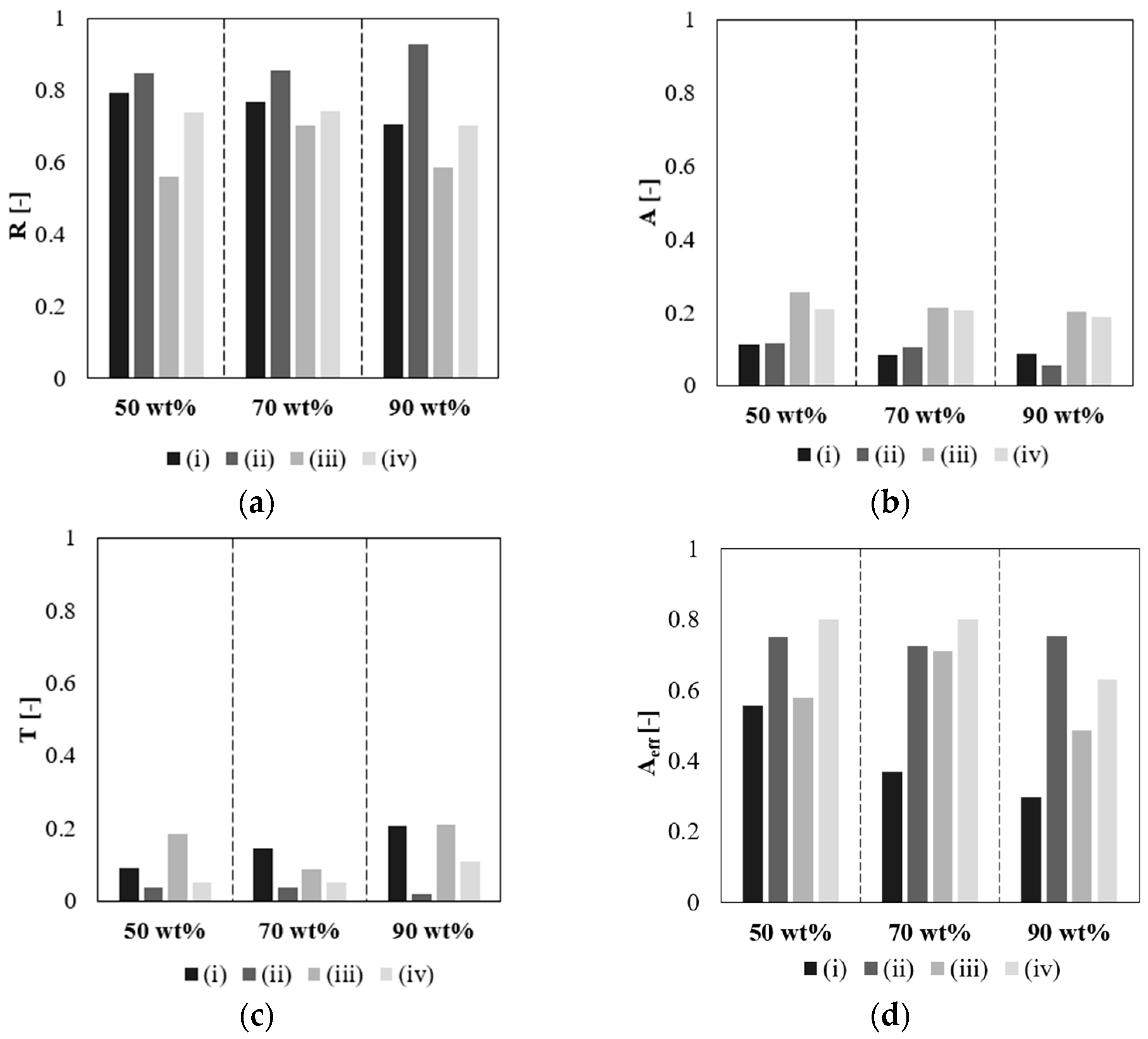
Further, a comparison between reflection, absorption, and transmission coefficients for all the four systems (i–iv) is reported in
Figure 5a–c for filler contents of 50, 70, and 90 wt%.
The reflection coefficient is higher in compact samples (i, ii) where the GNPs are perfectly aligned and the electrical conductivity is moderate–high (in the order of 104). This contribution also increases with thickness. Absorption is more pronounced in porous samples (iii, iv) and it changes slowly with the sample thickness.
All the samples show a low transmission coefficient (<20%), as reported in
Figure 5c, indicating that material is able to efficiently shield the EM waves. The lowest values are observed for samples with a high thickness and specifically for sample (ii).
To assess the material’s inherent absorption capacity, the effective absorption coefficient is estimated (Equation (4)) and reported in
Figure 5d.
Figure 5d confirms that porous samples (iii, iv) exhibit the highest absorption capacity and highlights that the absorption increases with the sample thickness.
A quantitative measure of EM shielding typically exploited is
SE, measured in decibels (dB) [
15]. In more detail, several contributions to the
SE are considered, the
SER, the
SEA, and the
SET defined below:
where
Pi,
Pr,
Pt, and
Pa are the incident, reflected, transmitted, and absorbed power referred to the sample, respectively.
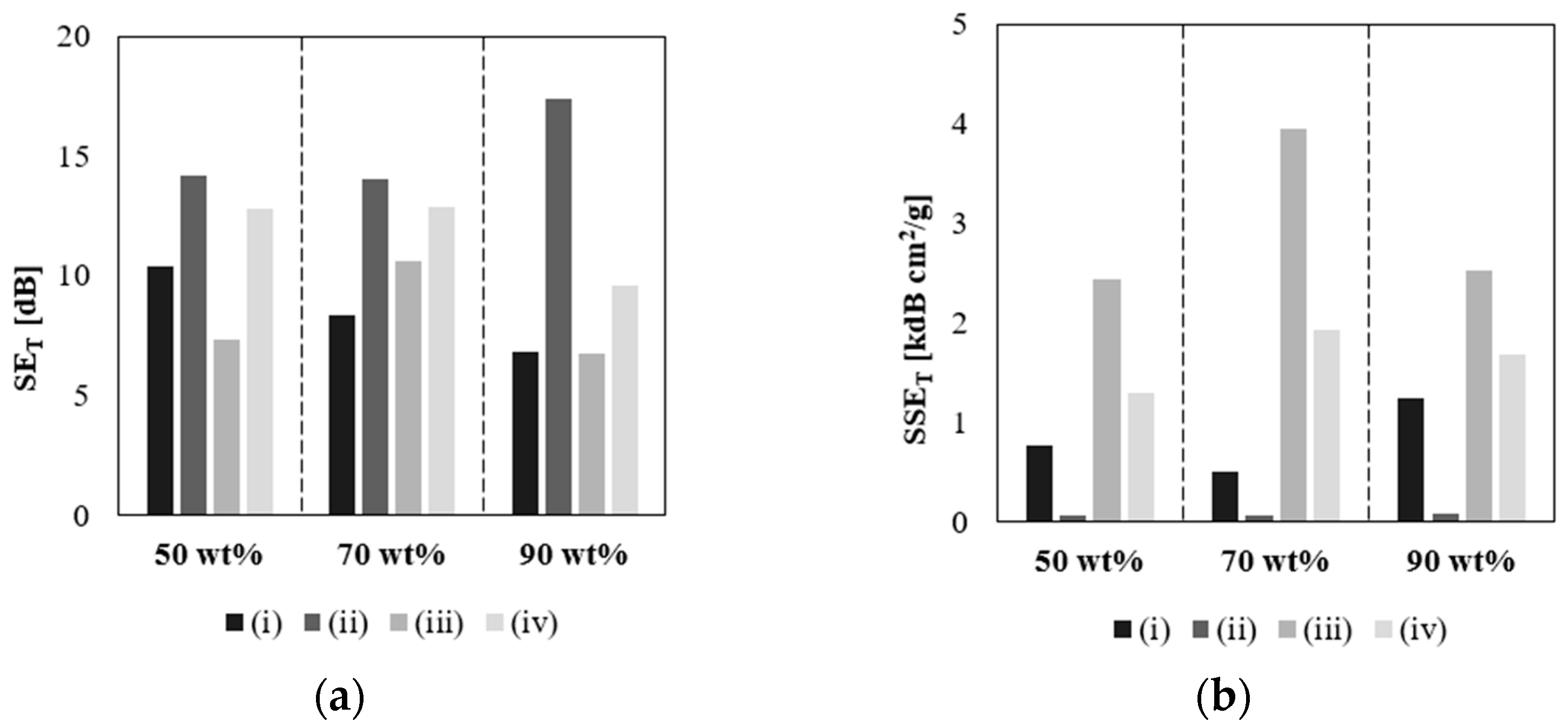
SET is reported in
Figure 6. It increases with increasing thickness both for compact and porous nanocomposites and it is maximum in the case of samples (ii).
Finally, in order to assess the EMI shielding performance of different materials per unit weight and thickness, the specific shielding effectiveness (
SSET) has been calculated according to Equation (6) by dividing
SET by the specimen density (
ρ) and thickness (
t) [
26]. This value, expressed in dB cm
2/g, is an absolute expression of the SE of the material. The highest value of 3958 dB cm
2/g has been observed for porous samples with the lowest thickness at 70 wt% of GNP content (
Figure 6).
4. Discussion
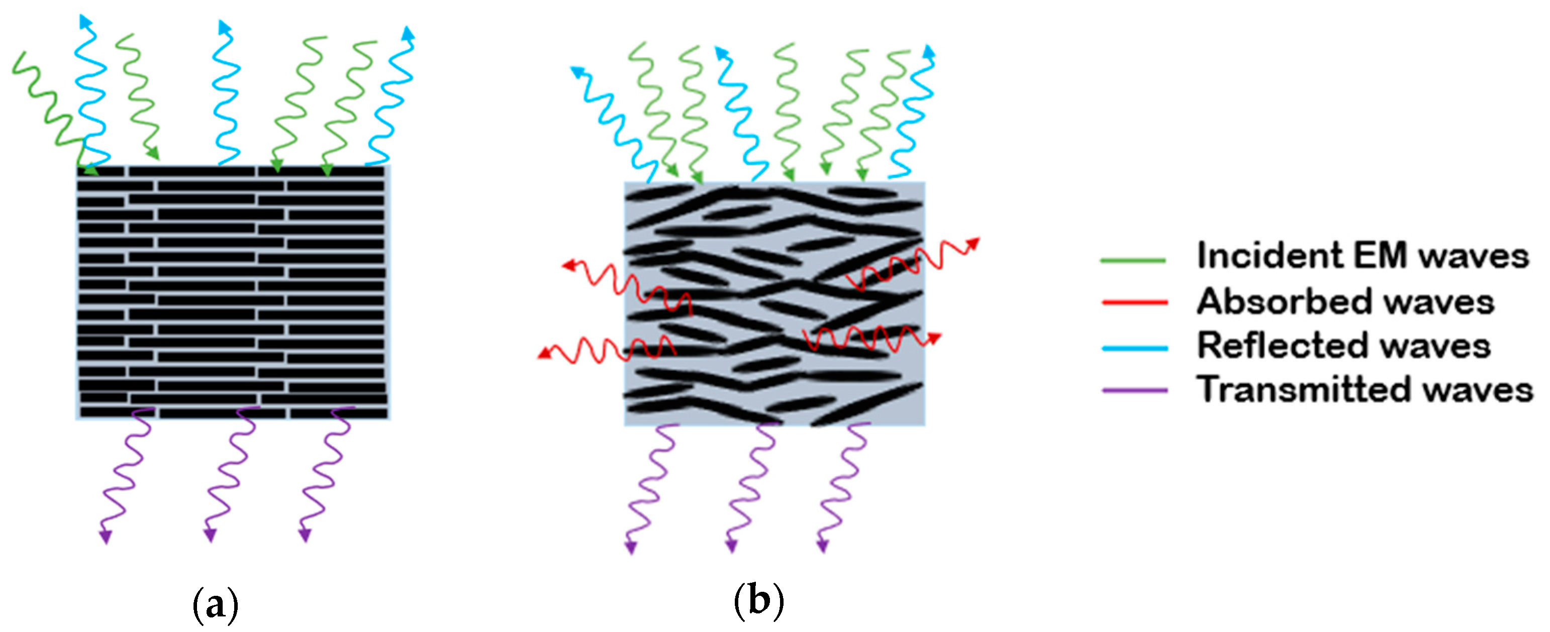
The power transmitted through the sample diminishes when reflection and absorption increase. Obviously, both the material characteristics and the nanocomposite’s architecture contribute to the two mechanisms above.
In samples with well-ordered nanostructure with nanoplatelets oriented in the plane direction, the EM waves are mainly reflected. In contrast, when the nanostructure is less organized and the nanoparticles are randomly oriented in the volume, reflection reduces and absorption can increase (
Figure 7).
By making the nanostructure porous, reflection decreases and absorption increases [
19]. Both for compact films at low filler content and porous samples, the chaotic structure allows better absorption. At the same time, the randomly oriented nanostructure reduces the reflection capacity of the material due to a worse alignment of the nanoplatelet of the surface. In the case of compact samples, a higher compaction pressure applied during the fabrication process leads to a higher level of alignment of the nanoplatelet, which results in a higher reflection capacity of the material.
By increasing the thickness of the sample, the transmission significantly reduces, being minimum in the case of compact thick samples (ii).
An increase in the absorption is observed when the fillers are unevenly distributed with respect to the compact samples. In contrast, the compact samples show a higher reflection with respect to the porous ones. In a laminated compact structure, the SE is mainly governed by reflection, since the densely stacked platelets are more favorable for reflecting the EM waves [
27]. On the other hand, in a porous structure, waves pass through the surface of the material, moving in a cell-like configuration [
19].
5. Conclusions
The SE in the X-band of graphene-based nanocomposites has been experimentally investigated. The effect of the material architecture on the capacity to attenuate the electromagnetic waves has been assessed through experimental analysis.
The nanoplatelet distribution influences the electromagnetic response of the material. A random orientation of nanoplatelets within the volume is associated to an increase in the absorption of the EM waves, while a well-oriented nanostructure to an increase in reflection.
It was found that, in a laminated compact structure, the SE is mainly governed by reflection, since the densely stacked platelets are more favorable for reflecting the EM waves. The maximum effective absorption of 80% was shown for system (iii) at 50 wt% content of filler, while a maximum reflection of 93% was shown for system (iv) at 90 wt% content of filler. Therefore, the materials are able to block the incident radiation thanks to a combined effect of absorption and reflection, with a maximum SEET of about 4000 dB cm2/g.


 ,
, 


