Article

Effects of Co-Solvent on the Morphology, Physicochemical Properties, and Performance of PVDF Electrospun Membranes in Comparison to Flat-Sheet Membranes

by
Reham A. Abd El-Latif
1,*,
Marwa E. Abdel Aziz
2,
Safaa H. El-Taweel
1,
Malak T. Abou El-Khair
2 and
Gamal R. Saad
1,*
1
Chemistry Department, Faculty of Science, Cairo University, Cairo 12613, Egypt
2
Advanced Materials Institute, Composite Materials Department, Central Metallurgical Research and Development Institute, Cairo 11422, Egypt
*
Authors to whom correspondence should be addressed.
J. Compos. Sci. 2022, 6(9), 253; https://doi.org/10.3390/jcs6090253
Submission received: 16 August 2022 / Revised: 22 August 2022 / Accepted: 24 August 2022 / Published: 29 August 2022
(This article belongs to the Section Fiber Composites)

Abstract

:
Poly(vinylidene fluoride) (PVDF) membranes were fabricated using two different methods: the electro-spinning technique and the phase inversion process. The effect of a DMF/acetone solvent composition on the quality of the electrospun fibers of the PVDF membrane was investigated. The prepared PVDF membranes have been characterized by scanning electron microscope (SEM), X-ray diffraction (XRD) and contact angle. Uniform fibrous membranes with fiber diameters ranging mainly from 6 μm to 1.5 μm were formed from 16% (w/w) PVDF solutions in 50/50 (w/w) DMF/acetone at 30 kV voltage and 0.3 mL/h flow rate. The effect of surface morphology and hydrophilicity on anti-fouling potential was also studied and compared with flat-sheet membranes. It was found that the spun fibrous membranes exhibited the best hydrophilicity and antifouling properties with an average pure water permeability up to 400 L/m2/h, higher than that of the flat-sheet membranes, which exhibited 200 L/m2/h. Performance evaluation of the prepared PVDF membranes (water flux and organic matter retention) has been done through the use of a dead-end apparatus, where the results demonstrated the efficiency of electrospun membrane over the conventionally prepared flat-sheet membrane for utilization as a pretreatment stage of ultrafiltration and microfiltration (MF/UF), before reverse osmosis (RO) in the desalination plant.

1. Introduction

Electrospinning has gained increasing interest as an application process that generates sub-micron to nano-scale fibers through an electrically charged jet of polymer solution [1,2,3]. Nowadays, many polymers have been successfully electrospun and significant research has been carried out to gain an in-depth understanding of the process for better control of fiber formation [4,5,6,7]. With the increased academic research, potential applications of electrospun fibers have also been identified, such as high-performance air filters [7], protective textiles [8,9], advanced composites [3], and, more recently, membranes in affinity separation [1,10,11,12].
Furthermore, new applications for membranes were considered in environmental protection and wastewater treatment utilizing electrospun polymeric membranes [13]. Generally, nanofibers acquire extremely high porosity, high surface area-to-volume ratio, high mechanical strength, and flexibility compared to conventional flat-sheet membranes [14,15]. However, the main challenge is its sophisticated process, which depends on several parameters, each of which significantly impacts the final product [5,16,17,18].
Because of its excellent properties, low cost, and chemical and thermal resistance, PVDF has become the most widely used polymer for membrane technology. Because of its good conductivity and piezoelectricity, it is now the most popular polymer for electrospinning. PVDF is a polymorphic material with distinct chain conformations, with the most common crystalline phases being: α -, β -, ε -, δ - and the γ -phase. Because the fluorine atom is more electronegative than the hydrogen and carbon atoms, the PVDF monomer has a strong electrical dipole moment, which results in piezoelectric properties and good conductivity. According to the PVDF chain conformation packing model, there is no net dipole in the α and ε phases, but there are net dipoles in β , γ , and δ phases. Among these three phases, the β phase has the highest dipolar moment per unit cell and provides the most piezoelectricity to PVDF. Numerous methods, including electrospinning, can induce the β phase [4,5].
Numerous research teams have studied the impact of the DMF/acetone ratio in the binary solvent system on the growth of free-defect fibers, fiber diameter, and porosity. It is demonstrated that the effects of the DMF/acetone ratio on fiber production and pore structure are substantial. The electrospun membranes were also researched for a variety of applications. According to Prasad and his colleagues, 18% PVDF could be developed into porous fibers by using different DMF/acetone ratios electrospun with thermally induced air and water inversion [19]. Zhao and coworkers created homogenous PVDF fibrous membranes from polymer concentration of 15 wt.% in an 80:20 (v/v) DMF/acetone mixture. The produced fiber sizes primarily ranged between 50 and 300 nm [20]. In order to create several PVDF polymer dope solutions to prepare nanofibrous mat, Liao and colleagues dissolved 5–12% PVDF in N,N-dimethyl acetamide (DMAc) and a mixture of 60:40% DMF to acetone; their research created and improved PVDF nanofiber membranes for use in membrane distillation application [21]. Lei and colleagues investigated the impact of utilizing different solvents; N-methyl-2-pyrrolidone, dimethyl sulfoxide, dimethylformamide, or dimethylacetamide and acetone, on the polymorphism and morphology of nanofibers made from electrospun PVDF membranes [22]. They found that polymer solutions with too fast or too slow evaporation rates of the solvents resulted in a large number of beads and/or beaded fibers with a low fraction of β-phase [23].
Based on the aforementioned, the current work aims to fabricate and characterize PVDF fibrous membranes produced by electrospinning. A solvent mixture of DMF/acetone was chosen as a key parameter of electrospinning conditions to achieve fibrous membranes with narrow fiber diameters. The surface morphology, crystallinity, and contact angle of the prepared electrospun membranes were compared to the flat-sheet membranes prepared under the same solution preparation conditions. Membrane permeability, humic acid (HA), and polystyrene micro-particles (PS) rejection were used to evaluate the membrane performance.

2. Materials and Methods

2.1. Materials

Commercial PVDF powder was purchased from Alfa Aesar, LOT: Q23A024 dried at 80 °C for 24 h before use. N,N- Dimethylformamide (DMF) as the main solvent of the dope solution and acetone as co-solvent were obtained from Fisher Scientific laboratory, Humic acid (HA) sodium salt technical grade and Polystyrene (PS) micro-particles 200 μm were purchased from Sigma-Aldrich.

2.2. Methods

2.2.1. Preparation of the Neat PVDF Solution

The PVDF casting solution was prepared by dissolving 16 wt.% PVDF powder in N,N-dimethylformamide (DMF) as a solvent at 70–90 °C under constant magnetic stirring (250 rpm) until obtaining a homogenous solution. After that, the solution was sonicated for 2 h to eliminate the bubbles and avoid membrane defects.

2.2.2. Preparation of the PVDF/Co-Solvent Binary System

DMF/acetone solvent mixtures were prepared with a weight ratio of 80/20, 60/40 and 50/50, respectively. PVDF was dissolved in the solvent mixtures at PVDF concentration, namely polymer/solvent weight ratio, of 16 wt.% PVDF powder. The polymer cast solution was also prepared under the same condition as the neat.

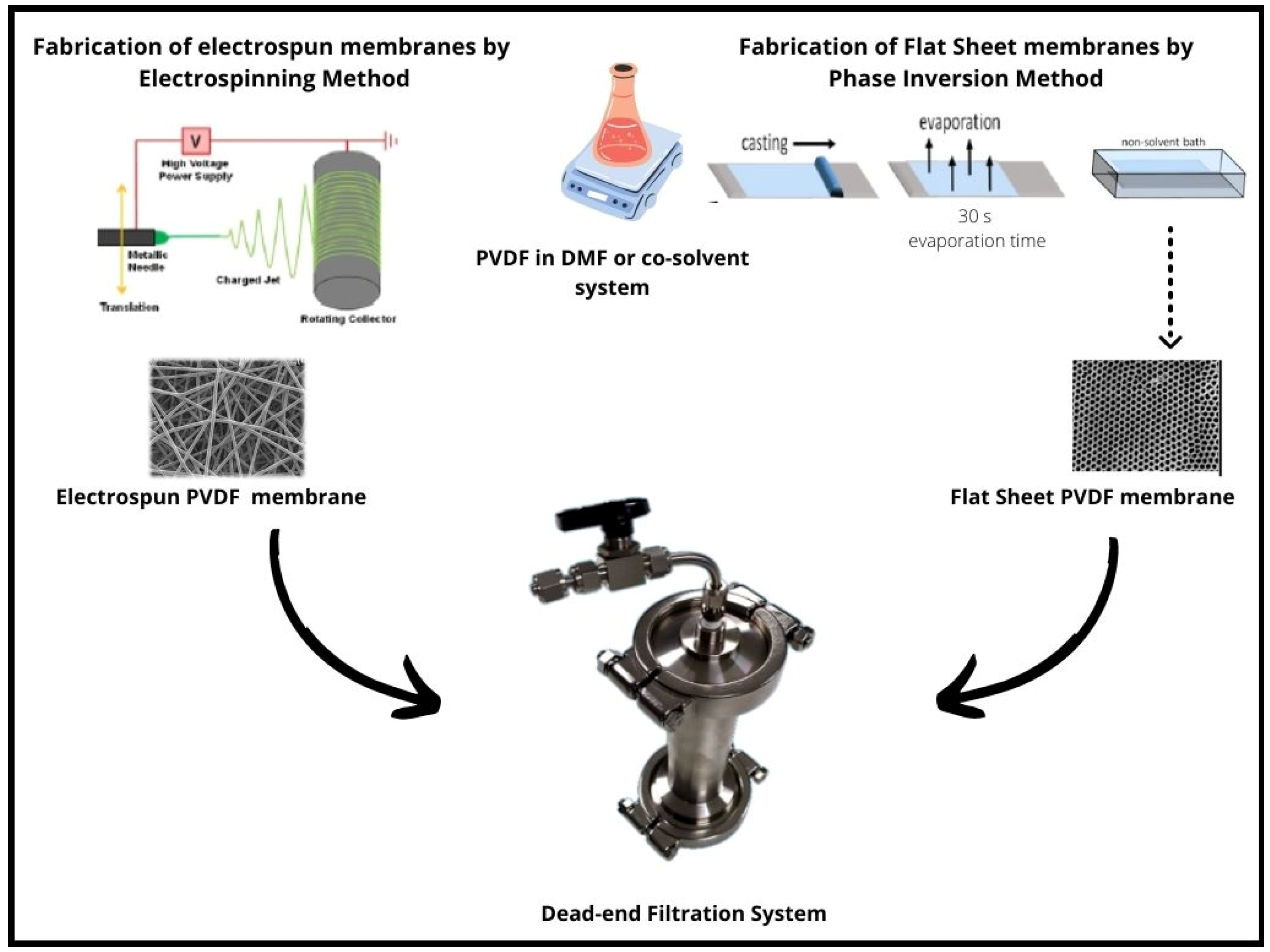
2.2.3. Fabrication of Nano-Fibrous Mats and Flat-sheet PVDF Membranes

PVDF solutions of 16% concentration with different DMF/acetone composition ratios were placed in a 5 mL syringe with a capillary tip having an inner diameter of 0.7 G. A syringe pump was used to feed the polymer solution into the needle tip, and the feed rate of the syringe pump was at 0.3 mL/h. PVDF fibers were electrospun at 30 kV with a high-voltage power supply. The fibers were fabricated using a NANON electrospinning setup that produces voltages ranging from 0–30 kV. A sheet of aluminum foil, connected to the collecting drum with 300 rpm speed, was placed at a fixed distance of 15 cm from the needle tip to collect the fibers. The temperature (T) was fixed at 30 °C, the voltage (V) at 30 kV and the feeding rate (v) at 0.3 mL/h.
Four PVDF membranes were prepared from PVDF solutions in 16% concentration with different DMF/acetone compositions 100/0, 80/20, 60/40, and 50/50, referenced here as PVDF’, PVDF’-1, PVDF’-2 and PVDF’-3, respectively.
For comparison, flat-sheet membranes in each concentration were prepared by phase inversion methods. PVDF solution 16% was poured on a flat horizontal glass plate and cast using a 200 μ m casting knife, and then the solvent was allowed to slowly evaporate in the air for 30 s. The casting and evaporation processes are followed by precipitation in a coagulation bath (distilled water of 4 °C). The casting process is carried out at room temperature. The membranes were removed from the coagulation bath and washed thoroughly with distilled water to remove residual solvents, and kept wet until use. Figure 1 shows a sketch of the preparation and fabrication methods of flat-sheet and fibrous electrospun PVDF membranes.
The prepared flat-sheet membranes were coded as PVDF, PVDF-1, PVDF-2 and PVDF-3 for the membranes prepared from 100/0, 80/20, 60/40 and 50/50 DMF/acetone solvents mixture, respectively.

2.2.4. Membranes Characterization

Scanning Electron Microscopy (SEM)

The morphologies of the neat flat-sheet and electrospun PVDF membranes were conducted using a scanning electron microscope (SEM) FEI, Quanta 250 FEG (Netherlands) type to identify the surface morphology and to assist in analyzing the average fiber diameter and pore size distribution. The average fiber diameter was calculated using appropriate software (ImageJ) and based on SEM images.

Wide Angle X-ray Diffraction (WAXD)
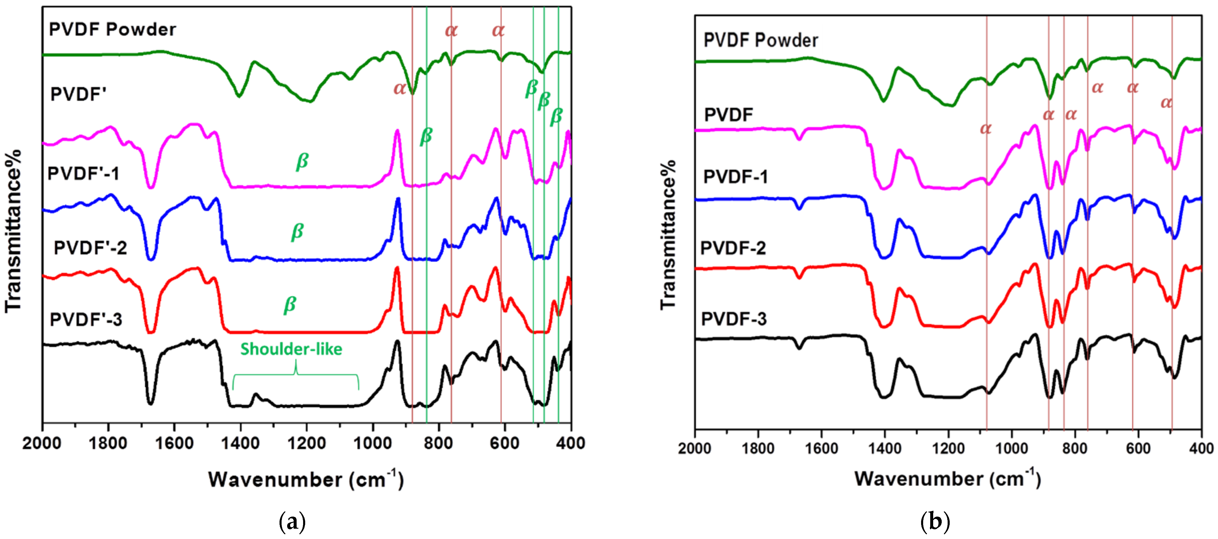
WAXD patterns of the membranes were measured with Philips Model PW 3710 X-ray diffraction instrument at a 2θ scanning rate of 2°/min in the range of 5° to 50° with a scanning rate of 2°/min. Cu Kα radiation was used for the diffraction with a voltage of 40 kV and a current of 100 mA.

FT-IR

FTIR of PVDF membranes was conducted with Shimadzu FTIR Spectrometer (800, Kyoto, Japan) in the wavenumber range 500–4000 cm−1.

Contact Angle

The sessile drop Technique was used to measure the contact angle (CA) using a KYOWA contact angle meter equipped with software for drop shape analysis. A droplet of deionized water was placed on the well-dried membrane samples. The analysis of samples was carried out at room temperature. The angle between the drop baseline and the tangent at the water drop boundary was measured by the mean on direct reading goniometry telescope. The droplet’s magnified image was analyzed and solved numerically the fitted using mathematical functions. Each value is an average of 3 independent measurements. The following equation was applied to evaluate the contact angle:
θ = 2 tan 1 ( 2 h w ) ,
where θ is the contact angle, h is the height, and w is the width of the droplet from the photograph and the geometric considerations.

Membranes Performance

An ultrafiltration experiment was performed in a lab-scale apparatus, whose schematic diagram is included in Figure 1, using nitrogen gas to power an ultrafiltration system with a 400 mL cylindrical beaker at a constant pressure of 1 bar on a dead-end stirred membrane evaluation cell with an effective filtration area of 5.0 × 10⁻⁴ m2. All the membrane samples were firstly pressurized with distilled water (pH 3.5) for 30 min before measurement. Two liters of deionized water were filtered through the cleaned membrane to achieve a stable initial flux. The ultrafiltration membrane of pure water flux was measured using 100 mL of deionized water. All ultrafiltration experiments were repeated three times to obtain mean values and standard deviations.
The OM rejection efficiency of all membrane samples was determined by using a 200 mL solution of 200 μm polystyrene (PS) micro-particles and 30 mg/L humic acids (HA) solution. The concentration of PS and HA in permeate and feed solutions during the filtration experiment was determined using a UV spectrophotometer. The HA concentration was determined by its UV absorption at the wavelength 254 nm and PS at 546 nm. All samples were 2 mL in volume and were measured in triplicate to meet QC/QA accordance.
The water flux ( J w ) through a semipermeable membrane expressed in the weight of the product per unit membrane area during operation time in liters (L m−2 h−1) was calculated as:
J w = Q A × t       ,
where Q is water permeates in liters, A is the membrane area in meter square, and t is the time in an hour.
The Organic Matter rejection percent R(%) was calculated as:
R ( % ) = ( C f   C p C f ) × 100 ,
where C f   and C p are the concentrations of feed and permeate water, respectively.

3. Results and Discussion
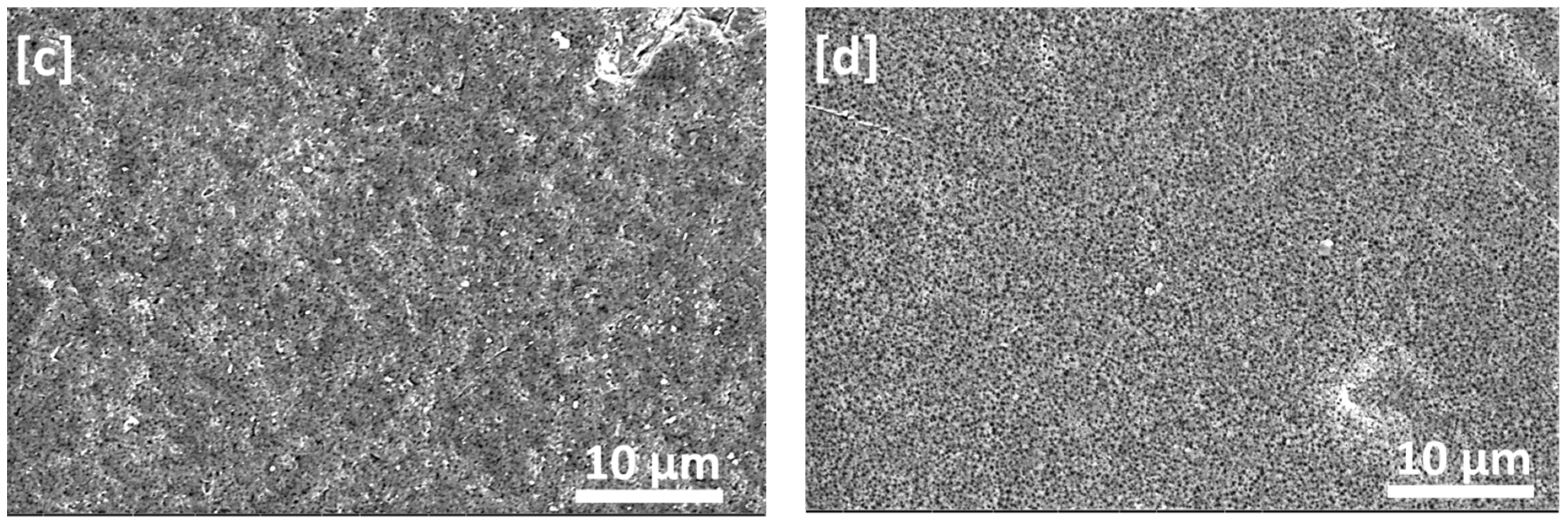
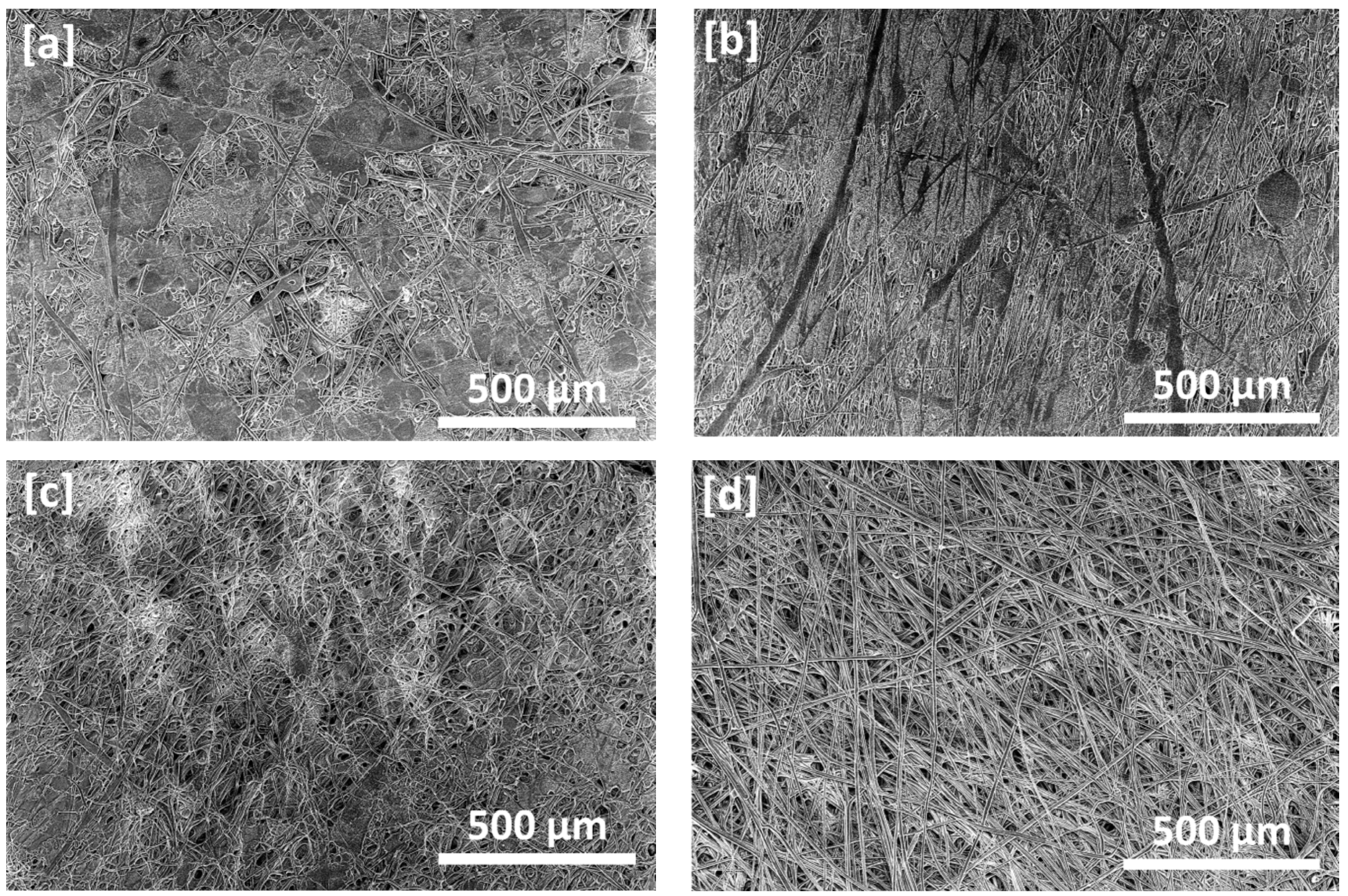
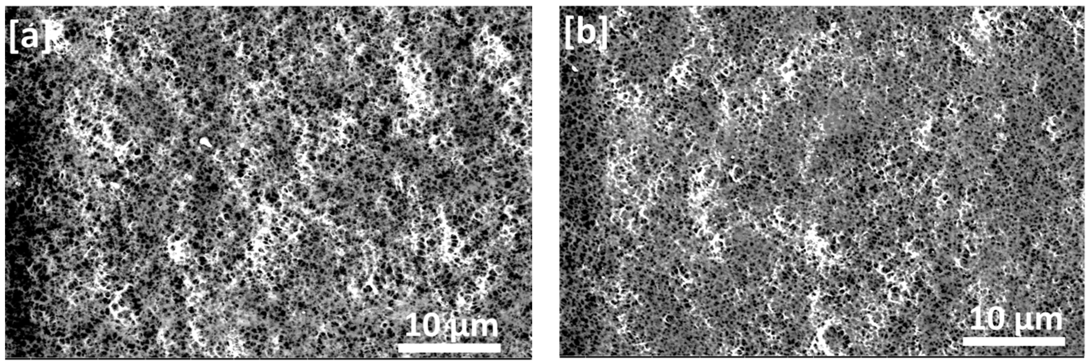
In general, it was more reasonable to generate ultrafine fibers by electrospinning from polymer solutions than from polymer melts. Therefore, the solvent used in polymer solutions for electrospinning was the most important factor determining the morphology of the electrospun fibers. Using polar DMF solvent could facilitate the formation of ultrafine fibers, but the lower volatility could make the ultrafine fiber generation difficult from polymer/DMF solutions alone. Acetone is more volatile and has low polarity than DMF, resulting in lower surface tension of the polymer solution and lowering its viscosity, which aids in the formation of the more uniform free-beads fiber. Furthermore, changes in solution properties caused by the addition of acetone may improve the morphology of electrospun membranes. With increasing acetone concentration, the electrospun fibers become more uniform.
A preliminary study of the effect of PVDF concentration on the fiber diameter showed that the greatest setting of the beads-free homogeneous fiber was achieved at 16 wt.% concentration of PVDF. Therefore, the aim is to provide information on the effect of solvent DMF/acetone compositions on the morphology of the produced fibers.

3.1. SEM Analysis

SEM micrographs of the PVDF fibers prepared by electrospinning from 16 wt.% PVDF solutions in different DMF/acetone composition ratios are shown in Figure 2a–d. It was observed that the average fiber diameter decreased from approximately 6 μ m to 1.6 μ m while the population and size of nodes and beads decreased and almost disappeared with increasing the ratio of acetone, which can be attributed to the low polarity and low boiling point of acetone compared with the electrospun fibers prepared using DMF alone, which has a higher boiling point (Figure 2a). Costa et al. reported similar results explaining that the decrease in fiber diameter has been caused by the low viscosity of the acetone solution since average fiber diameter has a directly proportional relationship with solution viscosity [5,12]. It was also obvious that the electrospun fibers became more and more uniform with the increase of acetone content in the solvent mixture (Figure 2c,d). Thus, the addition of acetone could likely improve the electrospun membrane morphology and decrease the possibility of bead formation, which is consistent with that reported previously [5,23,24,25]. Nuamcharoen et al. reported that increasing The addition of the volatile solvent with a low boiling point accelerated the evaporation of the mixed solvent, as previously reported for acetone. As a result of the volatile solvent being added to the PVDF/DMF solution, dried fibers were deposited on the surface of the collecting drum during the electrospinning process [25]. Zhao et al. also reported that with the addition of a certain amount of acetone to the electrospun PVDF solution, uniform ultrafine fibers could be generated [20].
Images of PVDF on the flat-sheet membranes are shown in Figure 3a–d. As can be seen, the membranes exhibited pores structure which became smaller and well distributed in the case of used mixed solvent compared with the pure DMF; this could be attributed to increasing the ratio of acetone in the solvent mixture, which lowers the precipitation rate of polymer [16].

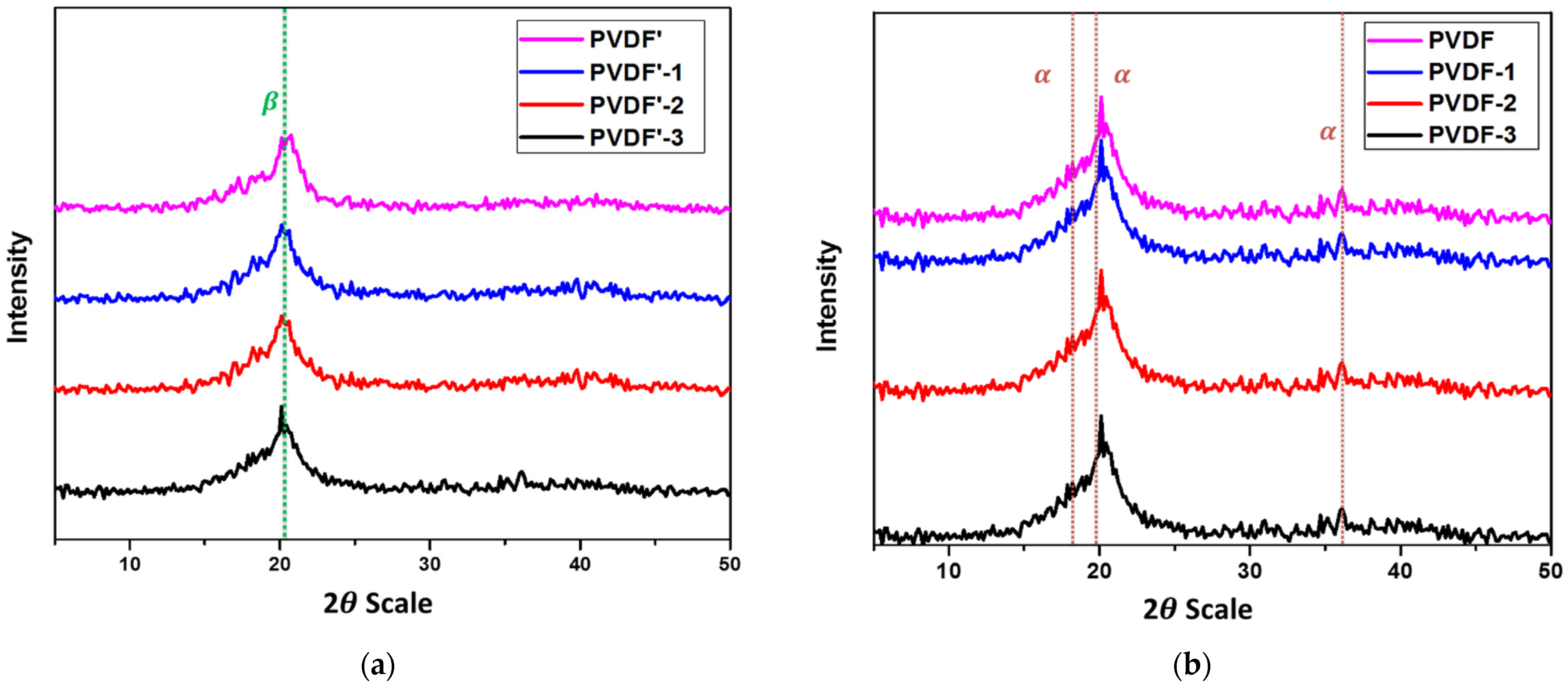
3.2. FTIR Analysis and WXRD

FTIR and WXRD were used to characterize the crystal structures of the electrospun PVDF membranes. FTIR spectra of electrospun PVDF fibrous membranes and flat-sheet membranes using mixed DMF/acetone solvents (100/0%, 80/20%, 60/40%, 50/50%) were displayed in Figure 4a and Figure 5b, respectively. The FT-IR spectra of PVDF provide valuable information about its structure, allowing different polymorphic states to be distinguished. However, some bands may overlap. The characteristic bands of the α -phase were observed at 408, 614, 766, and 855 cm−1 and at 510, 840, and 1279 cm−1 for the β -phase related bands [26], Table 1. The use of pure DMF as the solvent could lead to the coexistence of both α - and β -phase of PVDF. Nevertheless, when mixed DMF/acetone was used as the solvent, the intensity of the α -phase related absorption peaks decreased, and the characteristic peaks of the β -phase significantly increased. This might be explained by the fact that the addition of a volatile acetone solvent accelerates the evaporation rate of the solvent during the electrospinning process. This higher rate of evaporation may promote the nucleation and thereby the crystallization of the β -phase of PVDF [5,7,24,27,28,29,30].
Complementary information on the crystalline structure of the prepared membranes is given from XRD measurements in Figure 5a,b. For the sake of comparison, pure PVDF exhibited diffraction peaks of α -phase are located at 2 θ = 18.4° (020), β -phase at 20.6° (110/200) and 36.6° for α -phase and γ -phase at 20.3° (101) [27,31,32,33,34,35].
The PVDF electrospun membranes only exhibited two clear diffraction peaks at 20.0° and 22.4°, which decreased with increasing acetone ratio (Figure 5a), while the PVDF flat-sheet membranes showed clear diffraction peaks at 18.3°, 20.0° and 36.4° (Figure 5b), while The weak and diffuse diffraction peaks found in electrospun fibrous membranes compared with the raw powder and flat-sheet membranes suggesting the imperfection of α and β crystalline phases of PVDF. Thus, it could be concluded that the crystalline nature of PVDF was distributed by electrospinning compared with the raw material and the casting PVDF film [7,24,35,36,37,38].

3.3. Contact Angel

In general, the water contact angle is used to assess the hydrophilicity of surfaces. Hydrophobic films have larger contact angles than hydrophilic ones. Table 2 shows the results of static contact angle measurements on PVDF electrospun fibrous membranes compared to the same composition of flat-sheet membranes. Contact angle measurements revealed that increasing the acetone ratio in the co-solvent binary system increased the hydrophilicity of the membrane surface. As it can be observed, the contact angle on both membranes decreased as the acetone ratio in the solvent mixture increased and is less than 90°, indicating the hydrophilic character. Also, the decrease in contact angle value of PVDF electrospun fibrous membrane with increasing acetone in the solvent mixture was more significant than that of flat-sheet membranes, indicating that the fiber membrane has a higher hydrophilic character and thus excepted higher water permeability and consequently (as a result,) low fouling tendency [38].

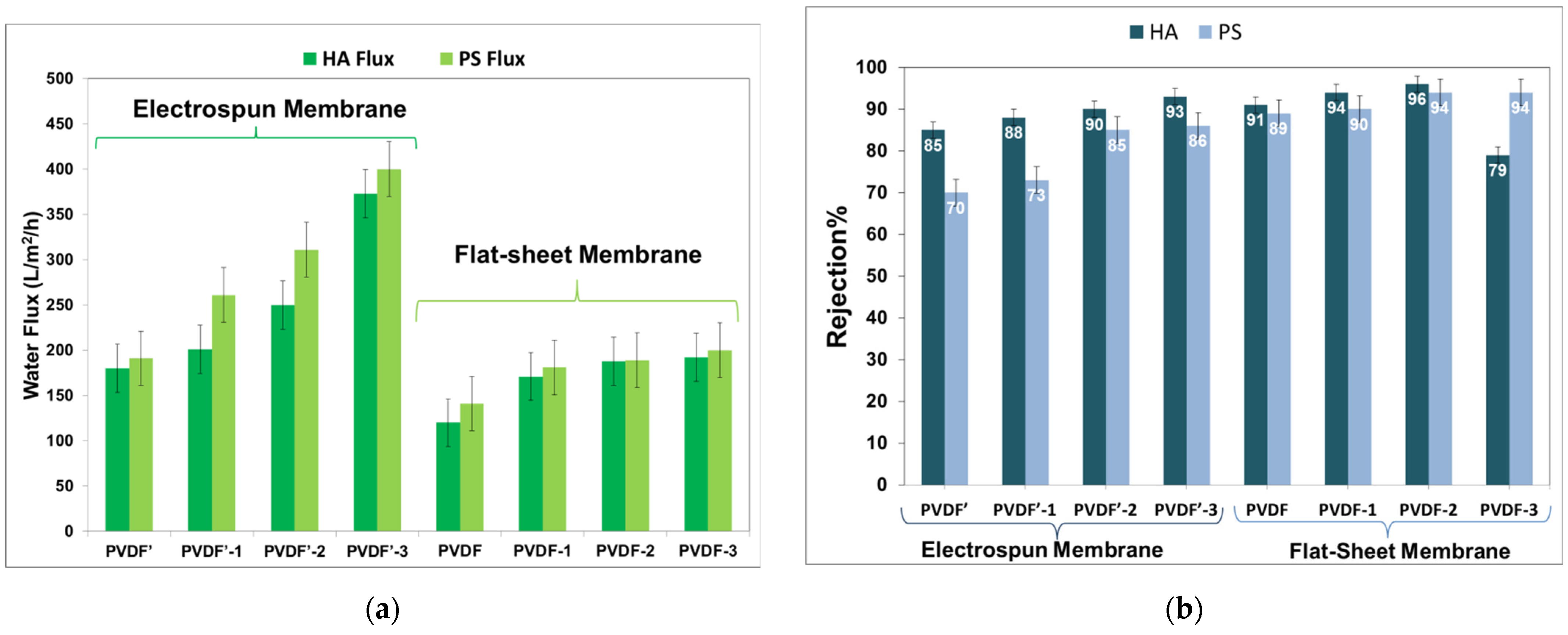
3.4. Membrane Performance

The water flux and rejection data of the prepared PVDF membranes with different PVDF/DMF/Acetone composition ratios of humic acid (HA) and polystyrene (PS) micro-particles, as models of filtration, are depicted in Figure 6a,b. As for the electrospun membrane prepared from pure DMF (sample PVDF’), the water flux was found to be around 180 ± 05 and 191 ± 05 L/m2/h, and R% 85% and 70% for HA and PS, respectively. For sample PVDF’-1 (prepared with 80/20, DMF/acetone), the water flux was found to be around 201 ± 12 and 261 ± 12, 91 ± 05 L/m2/h, and the R% was 88% and 73% for HA and PS, respectively. For sample PVDF’-1 (prepared with 60/40, DMF/acetone), the water flux was 250 ± 01 and 261 ± 121 and 91 ± 05 L/m2/h, and the R% was 88% and 73% for HA and PS, respectively. For sample PVDF’-2 (prepared with 60/40, DMF/acetone), water reflux up 250 ± 01 and 311 ± 01 L/m2/h and R% 90% and 85.5% were achieved for HA and PS, respectively. With increasing acetone content in the solvent mixture to 50% (sample PVDF’-3), the water flux and R% increased to 373 ± 10 and 400 ± 10 L/m2/h and R% to 93 and 86% for HA and PS. For the flat-sheet membrane prepared from pure DMF solvent (sample PVDF), water reflux of approximately180 ± 05 and 141 ± 04 L/m2/h and rejection efficiency (R%) of approximately 85% and 89% for humic acid (HA) solution and for polystyrene (PS) micro-particles, respectively, have been occurred. For the flat-sheet membrane prepared from DMF/acetone (80/20) solvent mixture (sample PVDF-1), the obtained water flux increased to 171 ± 01 and 181 ± 01 L/m2/h, and the R% increased to 94% and 91% for HA and PS, respectively. With increasing the amount of acetone in the solvent mixture to 40% (sample PVDF-2), the water flux increased to 188 ± 02 and 189 ± 02, while R% increased to 96% and 94% for HA and PS, respectively. Further increase of the water flux L/m2/h to 192 ± 05 and 200 ± 05 and R% to 94.5% was found by increasing acetone for HA and PS [26].
These data indicated that the water flux and rejection were improved by increasing the acetone in the solvent mixture, and the efficiency of electrospun membranes was better than the flat-sheet membranes. Increasing the acetone ratio of the solvent mixtures up to 50% might be increased the number of pores and decrease the pore size in the membrane. The increased porosity reflects the membrane’s increased hydrophilicity, resulting in higher flux. Furthermore, as pore size decreases, rejection efficiency increases. The increase in hydrophilicity of electrospun nanofibrous membranes, on the other hand, may be attributed to an increase in fiber homogeneity and a decrease in diameter with an increasing acetone ratio. Therefore, these results suggest that there is a relationship between the co-solvent ratio (Acetone, which has a lower boiling point and solvent/non-solvent diffusivity rate than the base pure DMF solvent) and the hydrophilicity and pore size of the nanofibrous and flat-sheet materials [27,35,38].
The filtration experiment was performed in a lab-scale apparatus whose schematic diagram is shown in Figure 1.

4. Conclusions

Flat-sheet and electrospun fibrous membranes PVDF from different DMF/acetone solvent mixtures were prepared and characterized. The study of surface morphologies of electrospun fibrous membrane indicated that the increase of acetone ratio promotes the formation of smaller fiber diameter and defect-free microstructure fibrous membrane, while in the case of flat-sheet membranes, it promotes the formation of tighter and more evenly distributed pores. FTIR and XRD showed that the α - and β crystalline phases of the electrospun fibrous were distributed compared with raw powder and flat-sheet membrane. The contact angle measurements decreased in both flat and fibrous membranes with increasing the acetone content in the solvent mixtures, indicating a decrease in hydrophobicity. According to the performance evaluation, the electrospun PVDF membrane outperformed that made from the same polymer at the same concentration and co-solvent binary system due to higher porosity as well as higher hydrophilicity.
Based on our preliminary findings, PVDF electrospun membranes have the potential to be used as microfiltration membranes to effectively remove micro-particles while causing no damage to the membrane. Such membranes have numerous potential applications, including water pretreatment. Water pretreatment currently consists of three sequential steps: coagulation, flocculation, and finally sedimentation. PVDF Electrospun membranes can be used instead of the three-step pretreatment process with proper module design. There is also the possibility of using these membranes as pre-filters prior to ultrafiltration or nanofiltration to reduce fouling and contamination from microorganisms or microparticles, as well as to separate cells. Time of writing, work is being done to modify PVDF in order to generate high-efficiency PVDF nanocomposite nanofibrous membranes for lab-scale separation in each of the potential applications listed above. This work opens the door to investigating the use of nanofibers in more mainstream separation technology applications.

Author Contributions

Methodology and writing—original draft preparation, R.A.A.E.-L.; resources, M.E.A.A. and S.H.E.-T.; supervision, G.R.S. and M.T.A.E.-K. All authors have read and agreed to the published version of the manuscript.

Funding

This research received no external funding.

Institutional Review Board Statement

Not applicable.

Informed Consent Statement

Not applicable.

Data Availability Statement

Data available upon request.

Acknowledgments

The authors would like to thank Mohamed Ateia for valuable discussions about membrane performance.

Conflicts of Interest

The authors declare no conflict of interest.

References

  1. Ahmed, F.E.; Lalia, B.S.; Hashaikeh, R. A review on electrospinning for membrane fabrication: Challenges and applications. Desalination 2015, 356, 15–30. [Google Scholar] [CrossRef]
  2. Gholami, A.; Moghadassi, A.; Hosseini, S.; Shabani, S. Preparation and characterization of polyvinyl chloride based nanocomposite nanofiltration-membrane modified by iron oxide nanoparticles for lead removal from water. J. Ind. Eng. Chem. 2014, 20, 1517–1522. [Google Scholar] [CrossRef]
  3. Ge, X.; Wu, S.; Shen, W.; Chen, L.; Zheng, Y.; Ao, F.; Ning, Y.; Mao, Y.; Chen, Z. Preparation of Polyvinylidene Fluoride–Gold Nanoparticles Electrospinning Nanofiber Membranes. Bioengineering 2022, 9, 130. [Google Scholar] [CrossRef]
  4. Bera, B.; Das Sarkar, M. Piezoelectricity in PVDF and PVDF Based Piezoelectric Nanogenerator: A Concept. IOSR J. Appl. Phys. 2017, 9, 95–99. [Google Scholar] [CrossRef]
  5. Costa, L.M.M.; Bretas, R.E.S.; Gregorio, R. Effect of Solution Concentration on the Electrospray/Electrospinning Transition and on the Crystalline Phase of PVDF. Mater. Sci. Appl. 2010, 1, 247–252. [Google Scholar] [CrossRef]
  6. Mohamadi, S. Preparation and Characterization of PVDF/PMMA/Graphene Polymer Blend Nanocomposites by Using ATR-FTIR Technique. In Infrared Spectroscopy—Materials Science, Engineering and Technology; InTech: London, UK, 2012. [Google Scholar] [CrossRef]
  7. Bui, T.T.; Shin, M.K.; Jee, S.Y.; Long, D.X.; Hong, J.; Kim, M.-G. Ferroelectric PVDF nanofiber membrane for high-efficiency PM0.3 air filtration with low air flow resistance. Colloids Surf. A Physicochem. Eng. Asp. 2022, 640, 128418. [Google Scholar] [CrossRef]
  8. He, R.; Li, J.; Chen, M.; Zhang, S.; Cheng, Y.; Ning, X.; Wang, N. Tailoring moisture electroactive Ag/Zn@cotton coupled with electrospun PVDF/PS nanofibers for antimicrobial face masks. J. Hazard. Mater. 2022, 428, 128239. [Google Scholar] [CrossRef]
  9. Wu, S.; Dong, T.; Li, Y.; Sun, M.; Qi, Y.; Liu, J.; Kuss, M.A.; Chen, S.; Duan, B. State-of-the-art review of advanced electrospun nanofiber yarn-based textiles for biomedical applications. Appl. Mater. Today 2022, 27, 101473. [Google Scholar] [CrossRef]
  10. Liao, Y.; Loh, C.-H.; Tian, M.; Wang, R.; Fane, A.G. Progress in electrospun polymeric nanofibrous membranes for water treatment: Fabrication, modification and applications. Prog. Polym. Sci. 2018, 77, 69–94. [Google Scholar] [CrossRef]
  11. Austria, H.F.M.; Subrahmanya, T.M.; Setiawan, O.; Widakdo, J.; Chiao, Y.-H.; Hung, W.-S.; Wang, C.-F.; Hu, C.-C.; Lee, K.-R.; Lai, J.-Y. A review on the recent advancements in graphene-based membranes and their applications as stimuli-responsive separation materials. J. Mater. Chem. A 2021, 9, 21510–21531. [Google Scholar] [CrossRef]
  12. Said, K.A.M.; Ismail, A.F.; Karim, Z.A.; Abdullah, M.S.; Hafeez, A.; Azali, M.A. Magnetic rod induced asymmetric membrane: Effect of iron oxide composition to phenol removal by adsorption. Mater. Chem. Phys. 2020, 258, 123862. [Google Scholar] [CrossRef]
  13. Teoh, G.H.; Ooi, B.S.; Jawad, Z.A.; Low, S.C. Impacts of PVDF polymorphism and surface printing micro-roughness on superhydrophobic membrane to desalinate high saline water. J. Environ. Chem. Eng. 2021, 9, 105418. [Google Scholar] [CrossRef]
  14. Bonyadi, S.; Chung, T.S. Flux enhancement in membrane distillation by fabrication of dual layer hydrophilic–hydrophobic hollow fiber membranes. J. Membr. Sci. 2007, 306, 134–146. [Google Scholar] [CrossRef]
  15. Leung, W.W.-F. Filtration characteristics of nanofiber filter and multilayer nanofiber filter for depth filtration. In Nanofiber Filter Technologies for Filtration of Submicron Aerosols and Nanoaerosols; Elsevier: Amsterdam, The Netherlands, 2022; pp. 145–183. [Google Scholar] [CrossRef]
  16. Huang, Z.-M.; Zhang, Y.-Z.; Kotaki, M.; Ramakrishna, S. A review on polymer nanofibers by electrospinning and their applications in nanocomposites. Compos. Sci. Technol. 2003, 63, 2223–2253. [Google Scholar] [CrossRef]
  17. Saleem, H.; Trabzon, L.; Kilic, A.; Zaidi, S.J. Recent advances in nanofibrous membranes: Production and applications in water treatment and desalination. Desalination 2019, 478, 114178. [Google Scholar] [CrossRef]
  18. Ewaldz, E.; Randrup, J.; Brettmann, B. Solvent Effects on the Elasticity of Electrospinnable Polymer Solutions. ACS Polym. Au. 2021, 2, 108–117. [Google Scholar] [CrossRef]
  19. Prasad, G.; Liang, J.-W.; Zhao, W.; Yao, Y.; Tao, T.; Liang, B.; Lu, S.-G. Enhancement of solvent uptake in porous PVDF nanofibers derived by a water-mediated electrospinning technique. J. Mater. 2020, 7, 244–253. [Google Scholar] [CrossRef]
  20. Zhao, Z.; Li, J.; Yuan, X.; Li, X.; Zhang, Y.; Sheng, J. Preparation and properties of electrospun poly(vinylidene fluoride) membranes. J. Appl. Polym. Sci. 2005, 97, 466–474. [Google Scholar] [CrossRef]
  21. Liao, Y.; Wang, R.; Tian, M.; Qiu, C.; Fane, A.G. Fabrication of polyvinylidene fluoride (PVDF) nanofiber membranes by electro-spinning for direct contact membrane distillation. J. Membr. Sci. 2012, 425-426, 30–39. [Google Scholar] [CrossRef]
  22. Lei, T.; Yu, L.; Wang, L.; Yang, F.; Sun, D. Predicting Polymorphism of Electrospun Polyvinylidene Fluoride Membranes by Their Morphologies. J. Macromol. Sci. Part B 2014, 54, 91–101. [Google Scholar] [CrossRef]
  23. Ribeiro, C.; Sencadas, V.; Ribelles, J.L.G.; Lanceros-Méndez, S. Influence of Processing Conditions on Polymorphism and Nanofiber Morphology of Electroactive Poly(vinylidene fluoride) Electrospun Membranes. Soft Mater. 2010, 8, 274–287. [Google Scholar] [CrossRef]
  24. Yin, J.-Y.; Boaretti, C.; Lorenzetti, A.; Martucci, A.; Roso, M.; Modesti, M. Effects of Solvent and Electrospinning Parameters on the Morphology and Piezoelectric Properties of PVDF Nanofibrous Membrane. Nanomaterials 2022, 12, 962. [Google Scholar] [CrossRef] [PubMed]
  25. Nuamcharoen, P.; Kobayashi, T.; Potiyaraj, P. Influence of volatile solvents and mixing ratios of binary solvent systems on morphology and performance of electrospun poly(vinylidene fluoride) nanofibers. Polym. Int. 2021, 70, 1465–1477. [Google Scholar] [CrossRef]
  26. Asai, H.; Terada, Y.; Nakane, K. Effects of the addition of protic organic solvents and the sample formation processes on the crystal structure of poly(vinylidene fluoride): Detailed mechanism of promoting the formation of the β-phase. Polymer 2022, 244, 124650. [Google Scholar] [CrossRef]
  27. Ruan, L.; Yao, X.; Chang, Y.; Zhou, L.; Qin, G.; Zhang, X. Properties and Applications of the β Phase Poly(vinylidene fluoride). Polymers 2018, 10, 228. [Google Scholar] [CrossRef] [PubMed]
  28. Su, R.; Zhong, G.; Fu, Q.; Zhang, L.; Fong, H.; Zhu, L. Polarity-induced ferroelectric crystalline phase in electrospun fibers of poly(vinylidene fluoride)/polyacrylonitrile blends. J. Mater. Res. 2012, 27, 1389–1398. [Google Scholar] [CrossRef]
  29. Li, Y.; Xu, M.-H.; Xia, Y.-S.; Wu, J.-M.; Sun, X.-K.; Wang, S.; Hu, G.-H.; Xiong, C.-X. Multilayer assembly of electrospun/electrosprayed PVDF-based nanofibers and beads with enhanced piezoelectricity and high sensitivity. Chem. Eng. J. 2020, 388, 124205. [Google Scholar] [CrossRef]
  30. Benedetti, E.; Catanorchi, S.; D’Alessio, A.; Moggi, G.; Vergamini, P.; Pracella, M.; Ciardelli, F. FTIR-Microspectroscopy andDSC Studies of Poly(vinylidene fluoride). Polym. Int. 1996, 41, 35–41. [Google Scholar] [CrossRef]
  31. Sengupta, D.; Kottapalli, A.G.P.; Chen, S.H.; Miao, J.M.; Kwok, C.Y.; Triantafyllou, M.S.; Warkiani, M.E.; Asadnia, M. Characterization of single polyvinylidene fluoride (PVDF) nanofiber for flow sensing applications. AIP Adv. 2017, 7, 105205. [Google Scholar] [CrossRef]
  32. Mun, J.; Park, H.M.; Koh, E.; Lee, Y.T. Enhancement of the crystallinity and surface hydrophilicity of a PVDF hollow fiber membrane on simultaneous stretching and coating method. J. Ind. Eng. Chem. 2018, 65, 112–119. [Google Scholar] [CrossRef]
  33. AVarposhti, A.M.; Yousefzadeh, M.; Kowsari, E.; Latifi, M. Enhancement of β-Phase Crystalline Structure and Piezoelectric Properties of Flexible PVDF/Ionic Liquid Surfactant Composite Nanofibers for Potential Application in Sensing and Self-Powering. Macromol. Mater. Eng. 2020, 305, 1900796. [Google Scholar] [CrossRef]
  34. Castkova, K.; Kastyl, J.; Sobola, D.; Petrus, J.; Stastna, E.; Riha, D.; Tofel, P. Structure–Properties Relationship of Electrospun PVDF Fibers. Nanomaterials 2020, 10, 1221. [Google Scholar] [CrossRef] [PubMed]
  35. Martins, P.; Lopes, A.C.; Lanceros-Mendez, S. Electroactive phases of poly(vinylidene fluoride): Determination, processing and applications. Prog. Polym. Sci. 2014, 39, 683–706. [Google Scholar] [CrossRef]
  36. Bodkhe, S.; Rajesh, P.S.M.; Kamle, S.; Verma, V. Beta-phase enhancement in polyvinylidene fluoride through filler addition: Comparing cellulose with carbon nanotubes and clay. J. Polym. Res. 2014, 21, 434. [Google Scholar] [CrossRef]
  37. Li, Z.; Wang, J.; Wang, X.; Yang, Q.; Zhang, Z. Ferro- and piezo-electric properties of a poly(vinyl fluoride) film with high ferro- to para-electric phase transition temperature. RSC Adv. 2015, 5, 80950–80955. [Google Scholar] [CrossRef]
  38. Gee, S.; Johnson, B.; Smith, A. Optimizing electrospinning parameters for piezoelectric PVDF nanofiber membranes. J. Membr. Sci. 2018, 563, 804–812. [Google Scholar] [CrossRef]
Figure 1. Schematic setup of electrospinning and phase inversion fabrication methods of PVDF Electrospun nanofibrous and flat-sheet membranes.
Jcs 06 00253 g001
Figure 2. SEM micrographs of PVDF electrospun fiber membranes prepared at 30 kV from DMF/acetone solutions with different compositions of solvent mixtures: (a) control membrane DMF/acetone: 100/0, (b) DMF/acetone: 80/20, (c). DMF/acetone: 60/40 and (d) DMF/acetone: 50/50.
Jcs 06 00253 g002
Figure 3. SEM micrographs of PVDF flat-sheet membranes fabricated by the phase inversion method from the DMF/acetone solutions with different compositions of solvent mixtures: (a) Control membrane DMF/acetone: 100/0, (b) DMF/acetone: 80/20, (c). DMF/acetone: 60/40 and (d) DMF/acetone: 50/50.
Jcs 06 00253 g003aJcs 06 00253 g003b
Figure 4. FTIR spectra of (a) electrospun PVDF fibrous membrane prepared in 100/0, 80/20, 60/40, and a 50/50 DMF/acetone solvent mixture. (b) FTIR spectra of PVDF flat-sheet membranes were prepared in 100/0, 80/20, 60/40, and 50/50 DMF/Acetone solvent mixture.
Jcs 06 00253 g004
Figure 5. (a) The XRD diffraction patterns of electrospun PVDF fibrous membranes were prepared in 100/0, 80/20, 60/40, and 50/50 DMF/acetone solvent mixture. (b) The XRD patterns of PVDF flat-sheet membranes were prepared in 100/0, 80/20, 60/40, and 50/50 DMF/acetone solvent mixtures.
Jcs 06 00253 g005
Figure 6. (a) The HA and PS Flux of electrospun fibrous and flat-sheet PVDF membranes corresponding to each membrane sample. (b) The HA and PS rejection efficiency of the electrospun fibrous and flat-sheet PVDF membranes corresponding to each membrane sample.
Jcs 06 00253 g006
Table 1. Summary table of the reported wavenumber values of alpha beta and gamma phases in literature.
α -Phase β -Phase γ -PhaseLiterature
Wavenumber cm−1408510431[16,35,36]
532840512[16,33,36]
6141279776[16,36,37]
766 812[33,36]
795 833[36]
855 840[36,37]
976 1234[16,36,37]
Table 2. Results of static contact angle measurements on PVDF electrospun fibrous membranes compared to the same composition of flat-sheet membranes.
Membrane TypeMembrane CodeContact Angle
Fibrous membranePVDF'60°
PVDF'-155°
PVDF'-243°
PVDF'-340°
Flat-sheet membranePVDF90°
PVDF-175°
PVDF-270°
PVDF-357°
Publisher’s Note: MDPI stays neutral with regard to jurisdictional claims in published maps and institutional affiliations.

