Article

Mechanical Properties of Dragline Silk Fiber Using a Bottom-Up Approach

Institute of General Mechanics, RWTH Aachen University, Eilfschornsteinstraße 18, 52062 Aachen, Germany
*
Author to whom correspondence should be addressed.
J. Compos. Sci. 2022, 6(3), 95; https://doi.org/10.3390/jcs6030095
Submission received: 18 February 2022 / Revised: 9 March 2022 / Accepted: 14 March 2022 / Published: 17 March 2022
(This article belongs to the Special Issue Feature Papers in Journal of Composites Science in 2022)

Abstract

:
We propose a molecular-based three-dimensional (3D) continuum model of dragline silk of Araneus diadematus, which takes into account the plasticity of the β -sheet crystals, the rate-dependent behavior of the amorphous matrix, and the viscous interface friction between them. For the proposed model, we computed the tensile properties, the effects of velocity on the mechanical properties, and hysteresis values, which are in good agreement with available experimental data. The silk fiber model’s yield point, breaking strength, post-yield stiffness, and toughness increased with increasing pulling velocity, while extensibility and the diameter of the silk fiber decreased. Our bottom-up approach has shed light on silk fiber mechanics, which can be used as an essential tool to design artificial composite materials.

1. Introduction

By virtue of its exceptional mechanical properties, spider silk is a protein fiber that has been a curiosity for humans for thousands of years. With up to seven different pairs of silk glands [1], Araneus diadematus, an orb-web spinning spider can produce silk for different purposes, each with its own unique mechanical properties. Dragline silk is observed to be the strongest amongst these, and it also happens to be amongst the toughest materials we know [2]. Dragline silk is secreted through the major ampullate gland, which forms the framework of the spider’s web [3]. In addition to this, the dragline silk is used for making the thread and radii that attach the web to the external structures [4].
The tensile strength of dragline silk fiber is comparable to that of high-carbon steel and higher than those of most polymeric biomaterials. Moreover, because of its much higher extensibility and stiffness, its toughness is unmatched in the world of synthetic and natural fibers [4,5]. Over the years, a wide range of applications of spider silk have been envisioned: tougher bulletproof clothing—as spider dragline can acquire extra toughness as a strain-hardening material by adopting the strategy of inserting certain molecular spindles, such as intramolecular β -sheets in silk fibrils [6]—elastic ligaments, ropes, nets, seat belts and parachutes [7,8]. Recently demonstrated applications, such as humidity alarm switches, smart doors and wound healing devices [9] showcase the diversity offered by spider silks.
Additionally, amongst other spider-related biomaterials, the study conducted by Kono et al. on golden orb-weaving spiders noted the influences of crucial molecular constituents on the mechanical properties of dragline silk. The study revealed a strong influence of SpiCE (spider-silk constituting element) separate from the unique spidroin structure’s influence [10]. Structurally comparable to dragline spider silk are new and artificially produced spidroins, such as the ones from the Araneoidea spider [10,11,12,13,14].
Figure 1 depicts the schematic construction of the dragline spider silk. The hierarchical structure of spider dragline silk can be seen as a semicrystalline material composed with amorphous flexible chains strengthened by sturdy and stiff crystals [15,16,17]. These crystals are made by polyalanine sequences arranged in β -sheets and form 10–25% of the dragline silk [2,18]. The existence of 3 1 helical, β -turn and β -spiral conformations has been suggested for the amorphous [17,18,19] domains; however, no definite atomistic-level structural model has yet been reported. It is predominantly disordered [20,21,22], and its longer peptide sequences are oriented along the fiber’s axis in stretch tests [2,23,24].
The specific secondary structures in the repeating units of the spider silk proteins are responsible for their mechanical properties [16]. A recent study conducted on dragline spider silk composite films showed a tendency to aggregate in the composite films and induce crystallization of the inherent silk β -sheet to afford rigid but brittle films [25]. Experimental investigation through a wide-angle X-ray scattering system has shown that during stretching, the orientation of the crystalline β -sheets aligned, whereas the crystallite size decreased [26].
Termonia’s network model [27] relies on molecular modeling of the crystalline and amorphous phases. This model is based upon a hypothesis of a hydrogen-bonded rubber matrix (amorphous phase) reinforced by a fraction of rigid crystal domains, acting as physical crosslink sites. There are several other hierarchical chain models, where spider silk is assumed to be constituted by bricks arranged in a hierarchical manner with a crystalline unit at the lowermost level [28,29]. Moreover, attempts at multiscale modeling of silk material have been made in recent years. In these approaches, the building-up principle for the macroscopic model was to consider a crystalline unit and an amorphous matrix as the prime constituents [30,31]. In the bottom-up approach, the simulations are carried out from the nanoscale to the macroscale—i.e., no empirical parameters are considered. Therefore, to study spider silk’s mechanical properties and behavior, the bottom-up approach offers good explanations. However, not a single model exists that enables a rigorous understanding of each constituent and the interface between them. Additionally, there has so far been no model available that could link molecular dynamics (MD) simulations to every macro-level finite element method (FEM) simulation of the full silk fiber model of the visco-elastoplastic material’s behavior.
Our previous study on the dragline spider silk showcased that long-range order arising from mechanical work performed on the material was vitally important to understanding of mechanics and properties of silk fibers [32]. In the present study, we have deduced a simple 3D fiber model to understand the unique mechanical properties of Araneus diadematus dragline silk using a bottom-up computational approach. In order to have a more realistic, purely bottom-up, macroscopic fiber model, we incorporated our previous work of nanoscale mechanical response of the crystalline unit [33], the amorphous phase [34] and their interface [35]. The mechanical properties of the spider silk fiber have already been determined with experiments. Our fiber model proved to be an effective fit to study the effect of pulling velocity on mechanical properties. In addition, mechanical hysteresis, the stress–strain curve does not follow the same path upon loading and unloading was investigated. Finally, the mechanical properties obtained from our simulations are compared with experimental values. The proposed molecular-based silk fiber model does not require any empirical parameters and contributes to an improved understanding of silk fiber mechanics during deformation. Hence, it is an efficient model for artificial silk fiber design and applicable to other composite materials. For a more detailed description of modeling and simulations of dragline spider silk, readers are referred to Patil [36].

2. Methods and Materials

Experimental studies using methods such as X-ray diffraction and atomic force microscopy, have established that the secondary structures of the amino acid motifs in the repetitive part of the proteins are responsible for the mechanical properties of the dragline silk [2,16,37]. However, direct links between the composition and the mechanical properties are not yet distinctly established. In our model, the stiff β -sheet crystals were considered as solid blocks, and the remaining matrix was the amorphous phase (Figure 2). To avoid model dependency, we considered four different fiber models with random arrangements of crystalline units. The random points for the center of masses of crystalline units were created using a normal (Gaussian) distribution. We used randomly generated units to avoid biased structural arrangements. Moreover, in this work, the mesh refinement was obtained by h-refinement. We considered mainly 3D linear hexahedrons (brick8) of different mesh sizes to study mesh independence. For this work, we considered an average length of 0.4 nm for brick8 elements. For more details, the reader is referred to our previous work, Patil et al. [33].
From our previous work, we arrived at the conclusion that the crystalline component of the silk fiber displays elastoplastic behavior and undergoes irreversible rupture against applied force [33]. The amorphous phase is softer and exhibits a rate-dependent behavior, i.e., a viscoelastic material [34]. Moreover, the third aspect is the viscous interface friction between the amorphous and crystalline phases [35]. In the literature, Sintya and Alam described the semi-crystalline nature of the contact surfaces [38]. In our previous work, atomistic MD simulations were utilized to obtain the friction forces for the relative sliding between the crystalline units and amorphous phase dragline silk [35]. Moreover, we computed the coefficient of viscosity of this interface to be in the order of 10 2 Ns/m 2 . In this work, the interface surfaces of the amorphous and crystalline units were constructed using two-dimensional (2D) shell elements, and the null material (MAT 009) was assigned to them. These contact surfaces are not an integral part of the main components. However, those are utilized to define areas of contact between the components. Therefore, the contact between the components was a fluid-like behavior. Here, we assigned the dynamic viscosity coefficient as input parameter, which was obtained from our previous work [35]. In this work, a Coulomb friction formulation and the segment-based penalty method were used to define contact [39]. For a detailed investigation of the friction modeling at the interface, we refer the readers to our previous work [35].
In the finite element (FE) modeling of the 3D fiber model, the commercial solver LS-DYNA (version: ls971s R5.1.1) [39] has been used. The key structural components and their mechanical behavior are summarized in Table 1.

3. Results and Discussion

Tensile test simulations were performed to gain a fundamental understanding of the mechanical properties, such as elasticity, strength and toughness. In this work, FE simulations at a macroscopic scale were based on the parameters derived from our previous MD simulations, and no empirical parameters were considered in the modeling. Therefore, the molecular-level changes were responsible for determining the exact stress–strain curve, which defines the macroscopic nature of the material. We carried out computational tensile tests on the 3D fiber model, and the results are presented for the random arrangement model. The model was fixed at one end and pulled at another end (Figure 2) with a pulling velocity of 0.4 m/s. Figure 3 shows the stress–strain curve of the Araneus diadematus dragline silk fiber model. For four different fiber models, the stress–strain curves are jointly analyzed (gray in Figure 3). The stress–strain curve was obtained by stretching a fiber and measuring the stress, σ required to extend the fiber model.
Since a wide variety of factors—pulling velocity, temperature, humidity, fiber defects, etc.—hold significant sway over the performance of the fiber, examining the mechanical properties of the spider dragline silk has been observed to be a complicated process [40,41]. In this work, we studied the influences of the pulling velocity on the mechanical properties of dragline silk. Pulling velocities in the same range as mentioned in previous experiments [40,42] have been considered. In the scope of this study, we took four random crystal arrangements in the 3D fiber model and six distinct pulling speeds (0.004, 0.01, 0.05, 0.1, 0.2, 0.4 m/s) for our FEM simulations. Figure 5 depicts the mechanical properties for dragline silk from the spider Araneus diadematus at different pulling velocities. The pulling velocity affects different mechanical properties differently, with some properties experiencing stronger effects than others.
Figure 4 shows the movement of crystalline units in the fiber model during loading. The stress–strain curve can be divided into three regions. Due to the high stiffness of crystalline units, the amorphous phase is deformed elastically in the linear elastic region. It is a local elastic deformation (reversible structural modifications) that occurs in the amorphous phase. In the yielding region, permanent structural changes are initiated, wherein crystalline units start to move, the fiber model diameter decreases and the amorphous phase starts to deform significantly. In the stiffening region, the crystalline units relocate in such a way that they form a series-like distribution in the fiber model. Here, maximum deformation of the amorphous phase can be observed.
The yield stress and the yield strain were unaffected by the pulling velocity for loading slower than 0.05 m/s. However, the same values increased for the range of 0.05 to 0.4 m/s (Figure 5a). The breaking stress saw a steep rise from 0.12 GPa to 0.65 GPa with the rise in pulling velocities (Figure 5b). On the other hand, the breaking strain value reduced from 50% to 35% as the pulling velocities rose, although this was not seen to be as big an effect as breaking stress. Such an interaction observed between the breaking stress and strain determines the magnitude of energy essential for breaking a fiber. We observed only a little velocity effect on the breaking strain. Hence, we concluded that the breaking stress was the critical factor for the determination of the breaking energy (Figure 5c). The post-stiffness modulus saw a significant rise with a rise in pulling velocities. Contrary to this, the fiber diameter expanded with a fall in pulling speed lower than 0.1 m/s and remained unchanged for all values greater than 0.1 m/s (Figure 5d).
With the rise in load on the silk fiber model, the amorphous chains are extended and align themselves in the fiber axis direction along with the aligned crystalline units, i.e., increase in elastic limit at the macroscale (see Figure 5a). The strain that gets removed when unloading is in progress can be termed as an elastic strain, whereas the plastic strain is the one that remains even after the unloading is completed. Naturally, total strain is the sum of these two elastic and plastic strains. Considering this for the crystalline units of the 3D fiber model, one can be certain that plastic strains are experienced by the crystalline units. When subject to fast pulling, plastic deformation with a high slope starts for the crystalline units. This, in turn, is responsible for higher stiffness, and by definition, lower fiber extensibility.
The mechanical properties are primarily influenced by pulling velocity as time is given to the polypeptide chains of the amorphous phase for an alignment with the direction of loading, i.e., increase in strength of the fiber model (see Figure 5c). At the amorphous-crystalline interface, a viscous relaxation happens within the amorphous matrix along with the fiber. This is nothing but the alignment of amorphous chains along the loading direction. We encoded the relaxation time scale as the coefficient of viscosity in the FE simulations, which do not particularly provide details about coiling and the polypeptide chain arrangement. Lower pulling velocities allow the amorphous chains to have enough time to relax. This is why as the amorphous chains align along the fiber axis, a significant elongation or a considerable strain is observed with a substantial drop in fiber diameter (see Figure 6a). Higher pulling velocities limit the deformation, as they do not allow amorphous chains to align with the fiber axis because of the short time. As a result of this, there is a steep decrease in breaking strain, and the breaking stress rises with a rise in pulling velocity (see Figure 5c,d). Due to all these factors, we see higher toughness for faster pulling velocities (see Figure 6b).
While modeling the silk fibers, one can construct two kinds of models for random packaging of crystalline units—with slip and no-slip conditions. In the case of the no-slip condition, there are no surfaces present because of the node-to-node connectivity. The elements have node-to-node connectivity, and therefore possess higher stiffness. This higher stiffness, in turn, is responsible for a lowered toughness (due to low ductility). With the slip condition, the surfaces of the crystalline and the amorphous (green and yellow) are present, as shown in Figure 1. Therefore, during pulling of the fiber model, crystalline units can rearrange themselves. In our previous work, we noted that the fiber models’ toughness for randomly ordered and distributed crystalline units with the slip condition is about 119 MJ/mm 3 , whereas for the no-slip condition, it is about 91 MJ/mm 3 . For more details, refer to our previous work [36].
From the observations in our simulations on the effects of pulling velocity on several mechanical property parameters, such as yield stress, yield strain, breaking stress, breaking strain and fiber diameter, we see good agreement with the previous experimental works by Vollrath et al. [43]. Other parameters, such as the post-yield stiffness and toughness were found to be in agreement with the work of Du et al. [37].
Visco-elasticity as well non-reversible deformation are responsible for hysteresis, which is nothing but deformation that is history-dependent. After completing one loading-unloading cycle, the energy dissipated in the material is measured by the area under the curve, i.e., the surface area enclosed by the loop of hysteresis. A time-dependent hysteresis is observed for the 3D fiber model due to its visco-elastoplastic behavior. To examine the hysteresis of the silk model, we considered that the fiber was subject to load value smaller than the rupture stress and then unloaded.
Figure 7a depicts typical hysteresis plots of individual loading-unloading cycles with 0.4 m/s pulling velocities of the dragline silk fiber. Five individual hysteresis plots denote the elongation of the silk fiber from 8% to 30% of the original length and then unloading it. Figure 7b shows load cycle 4 with an elongation up to 21% of the original length followed by unloading. Hysteresis is the ratio of dissipated energy to the absorbed energy. Deformation of silk fiber resulted in 72 ± 2% loss of energy. These values of hysteresis are in close agreement with previous values from loading-unloading experiments of 67.6 ± 2.6% [2,4,44].
Internal molecular friction is believed to be the cause of high levels of hysteresis seen in dragline silks. Particularly, beyond the yield point, the polypeptide bonds break, and the polypeptide chains are seen to slide and reorient themselves relative to each other [2,45]. Later, once a new and stable conformation is achieved, the polypeptide chains relax and develop new bonds. This is why, when unloaded, the new conformation leads to irreversible deformation that is responsible for stopping the full recovery at relaxation. FE calculations cannot infer this micro-level interpretation of events, as viscosity and plasticity incorporate these effects implicitly.

4. Conclusions

To conclude, our 3D fiber model included not only the amorphous phase to represent the viscoelastic behavior and the crystalline units for the elastoplastic material behavior, but also the relative sliding (friction) behavior between them. With the help of the fiber model, we have increased our understanding of the essential mechanical parameters. The values of parameters such as strength, extensibility, initial stiffness, post-stiffness, toughness and hysteresis obtained from the finite element simulations are in remarkable agreement with the currently accessible experimental data (Table 2).
The rate-dependent behavior of the amorphous phase is mainly responsible for the influence of the pulling velocity on the mechanical properties of the silk fiber. We demonstrated that silk fiber’s yield point, breaking strength, post-yield stiffness and toughness increased with increasing pulling velocity, while extensibility and the diameter of the silk fiber decreased. We found that the initial stiffness of the fiber is due to the initial random arrangement of crystals. At the same time, in the post-yield region, the combination of high extensibility and high strength results in the high toughness of the fiber.
Our model has some limitations, and so far, we have not successfully reproduced the noticeably higher nonlinear behavior observed in the post-yield region. This limitation of our model might be due to the amorphous phase, a fully continuously modeled matrix with a basic viscoelastic material model. We believe that improvements in the current model can be made by assuming a worm-like chain behavior and modeling it into the user-defined material subroutine (UMAT) for FE analysis, which might better capture this region.
Our bottom-up approach elucidated how the atomistic structure influences the material properties at the macroscale. Therefore, it is, in our opinion, a helpful tool for designing artificial composite materials. Structurally similar biomaterials can be modeled using the presented approach.

Author Contributions

Conceptualization, S.P.P. and B.M.; methodology, S.P.P. and B.M.; software, S.P.P.; validation, S.P.P.; formal analysis, S.P.P. and B.M.; investigation, S.P.P. and B.M.; data curation, S.P.P. and A.K.; writing–original draft preparation, S.P.P. and A.K.; visualization, S.P.P.; supervision, S.P.P. and B.M. All authors have read and agreed to the published version of the manuscript.

Funding

This research received no external funding.

Institutional Review Board Statement

Not applicable.

Informed Consent Statement

Not applicable.

Data Availability Statement

Data can be made available on request.

Acknowledgments

The authors gratefully acknowledge the computing time granted by the JARA Vergabegremium and provided on the JARA Partition of the supercomputer CLAIX at RWTH Aachen University.

Conflicts of Interest

The authors declare no conflict of interest.

References

  1. Candelas, G.C.; Cintron, J. A spider fibroin and its synthesis. J. Exp. Zool. 1981, 216, 1–6. [Google Scholar] [CrossRef]
  2. Gosline, J.M.; Guerette, P.A.; Ortlepp, C.S.; Savage, K.N. The mechanical design of spider silks: From fibroin sequence to mechanical function. J. Exp. Biol. 1999, 202, 3295–3303. [Google Scholar] [CrossRef]
  3. Vollrath, F.; Knight, D.P. Liquid crystalline spinning of spider silk. Nature 2001, 410, 541–548. [Google Scholar] [CrossRef]
  4. Denny, M.W. The physical properties of spider’s silk and their role in the design of orb-webs. J. Exp. Biol. 1976, 65, 483–506. [Google Scholar] [CrossRef]
  5. Gosline, J.M.; DeMont, M.E.; Denny, M.W. The Structure and Properties ofSpider Silk. Endeavour 1986, 10, 37–43. [Google Scholar] [CrossRef]
  6. Du, N.; Yang, Z.; Liu, X.Y.; Li, Y.; Xu, H.Y. Structural origin of the strain-hardening of spider silk. Adv. Funct. Mater. 2011, 21, 772–778. [Google Scholar] [CrossRef]
  7. Kaplan, D.L. Fibrous proteins-silk as a model system. Polym. Degrad. Stab. 1998, 59, 25–32. [Google Scholar] [CrossRef]
  8. Altman, G.H.; Diaz, F.; Jakuba, C.; Calabro, T.; Horan, R.L.; Chen, J.; Lu, H.; Richmond, J.; Kaplan, D.L. Silk-based biomaterials. Biomaterials 2003, 24, 401–416. [Google Scholar] [CrossRef] [Green Version]
  9. Dong, L.; Qiao, J.; Wu, Y.; Ren, M.; Wang, Y.; Shen, X.; Wei, X.; Wang, X.; Di, J.; Li, Q. Programmable Contractile Actuations of Twisted Spider Dragline Silk Yarns. ACS Biomater. Sci. Eng. 2021, 7, 482–490. [Google Scholar] [CrossRef]
  10. Kono, N.; Nakamura, H.; Ohtoshi, R.; Moran, D.A.P.; Shinohara, A.; Yoshida, Y.; Fujiwara, M.; Mori, M.; Tomita, M.; Arakawa, K. Orb-weaving spider Araneus ventricosus genome elucidates the spidroin gene catalogue. Sci. Rep. 2019, 9, 8380. [Google Scholar] [CrossRef]
  11. Kono, N.; Ohtoshi, R.; Malay, A.D.; Mori, M.; Masunaga, H.; Yoshida, Y.; Nakamura, H.; Numata, K.; Arakawa, K. Darwin’s bark spider shares a spidroin repertoire with Caerostris extrusa but achieves extraordinary silk toughness through gene expression. Open Biol. 2021, 11, 210242. [Google Scholar] [CrossRef]
  12. Kono, N.; Nakamura, H.; Mori, M.; Yoshida, Y.; Ohtoshi, R.; Malay, A.D.; Moran, D.A.P.; Tomita, M.; Numata, K.; Arakawa, K. Multicomponent nature underlies the extraordinary mechanical properties of spider dragline silk. Proc. Natl. Acad. Sci. USA 2021, 118, e2107065118. [Google Scholar] [CrossRef]
  13. Sheffer, M.M.; Hoppe, A.; Krehenwinkel, H.; Uhl, G.; Kuss, A.W.; Jensen, L.; Jensen, C.; Gillespie, R.G.; Hoff, K.J.; Prost, S. Chromosome-level reference genome of the European wasp spider Argiope bruennichi: A resource for studies on range expansion and evolutionary adaptation. Gigascience 2021, 10, giaa148. [Google Scholar] [CrossRef]
  14. Miller, J.; Vienneau-Hathaway, J.; Dendev, E.; Lan, M.; Ayoub, N.A. The common house spider, Parasteatoda tepidariorum, maintains silk gene expression on sub-optimal diet. PLoS ONE 2020, 15, e0237286. [Google Scholar] [CrossRef]
  15. Glišovic, A.; Vehoff, T.; Davies, R.J.; Salditt, T. Strain dependent structural changes of spider dragline silk. Macromolecules 2008, 41, 390–398. [Google Scholar] [CrossRef]
  16. Hayashi, C.Y.; Shipley, N.H.; Lewis, R.V. Hypotheses that correlate the sequence, structure, and mechanical properties of spider silk proteins. Int. J. Biol. Macromol. 1999, 24, 271–275. [Google Scholar] [CrossRef]
  17. van Beek, J.D.; Hess, S.; Vollrath, F.; Meier, B.H. The molecular structure of spider dragline silk: Folding and orientation of the protein backbone. Proc. Natl. Acad. Sci. USA 2002, 99, 10266–10271. [Google Scholar] [CrossRef] [Green Version]
  18. Lefèvre, T.; Rousseau, M.; Pézolet, M. Protein secondary structure and orientation in silk as revealed by Raman spectromicroscopy. Biophys. J. 2007, 92, 2885–2895. [Google Scholar] [CrossRef] [Green Version]
  19. Cunniff, P.M.; Fossey, S.A.; Auerbach, M.A.; Song, J.W.; Kaplan, D.L.; Adams, W.W.; Eby, R.K.; Mahoney, D.; Vezie, D.L. Mechanical and thermal properties of dragline silk from the spider Nephila clavipes. Polym. Adv. Technol. 1994, 5, 401–410. [Google Scholar] [CrossRef]
  20. Simmons, A.; Ray, E.; Jelinski, L.W. Solid-state 13C NMR of Nephila clavipes dragline silk establishes structure and identity of crystalline regions. Macromolecules 1994, 27, 5235–5237. [Google Scholar] [CrossRef]
  21. Oroudjev, E.; Soares, J.; Arcidiacono, S.; Thompson, J.B.; Fossey, S.A.; Hansma, H.G. Segmented nanofibers of spider dragline silk: Atomic force microscopy and single-molecule force spectroscopy. Proc. Natl. Acad. Sci. USA 2002, 99, 6460–6465. [Google Scholar] [CrossRef] [Green Version]
  22. Hinman, M.B.; Lewis, R.V. Isolation of a clone encoding a second dragline silk fibroin. Nephila clavipes dragline silk is a two-protein fiber. J. Biol. Chem. 1992, 267, 19320–19324. [Google Scholar] [CrossRef]
  23. Porter, D.; Vollrath, F.; Shao, Z. Predicting the mechanical properties of spider silk as a model nanostructured polymer. Eur. Phys. J. E 2005, 16, 199–206. [Google Scholar] [CrossRef]
  24. Brookes, V.L.; Young, R.J.; Vollrath, F. Deformation micromechanics of spider silk. J. Mater. Sci. 2008, 43, 3728–3732. [Google Scholar] [CrossRef]
  25. Tsuchiya, K.; Ishii, T.; Masunaga, H.; Numata, K. Spider dragline silk composite films doped with linear and telechelic polyalanine: Effect of polyalanine on the structure and mechanical properties. Sci. Rep. 2018, 8, 3564. [Google Scholar] [CrossRef] [Green Version]
  26. Yazawa, K.; Malay, A.D.; Masunaga, H.; Norma-Rashid, Y.; Numata, K. Simultaneous effect of strain rate and humidity on the structure and mechanical behavior of spider silk. Commun. Mater. 2020, 1, 10. [Google Scholar]
  27. Termonia, Y. Molecular Modeling of Spider Silk Elasticity. Macromolecules 1994, 27, 7378–7381. [Google Scholar] [CrossRef]
  28. Becker, N.; Oroudjev, E.; Mutz, S.; Cleveland, J.P.; Hansma, P.K.; Hayashi, C.Y.; Makarov, D.E.; Hansma, H.G. Molecular nanosprings in spider capture-silk threads. Nat. Mater. 2003, 2, 278–283. [Google Scholar] [CrossRef]
  29. Zhou, H.; Zhang, Y. Hierarchical chain model of spider capture silk elasticity. Phys. Rev. Lett. 2005, 94, 028104. [Google Scholar] [CrossRef] [Green Version]
  30. Nova, A.; Keten, S.; Pugno, N.M.; Redaelli, A.; Buehler, M.J. Molecular and Nanostructural Mechanisms of Deformation, Strength and Toughness of Spider Silk Fibrils. Nano Lett. 2010, 10, 2626–2634. [Google Scholar] [CrossRef] [Green Version]
  31. Cetinkaya, M.; Xiao, S.; Markert, B.; Stacklies, W.; Gräter, F. Silk fiber mechanics from multiscale force distribution analysis. Biophys. J. 2011, 100, 1298–1305. [Google Scholar] [CrossRef] [Green Version]
  32. Wagner, J.A.; Patil, S.P.; Greving, I.; Lämmel, M.; Gkagkas, K.; Seydel, T.; Müller, M.; Markert, B.; Gräter, F. Stress-induced long-range ordering in spider silk. Sci. Rep. 2017, 7, 15273. [Google Scholar] [CrossRef] [Green Version]
  33. Patil, S.P.; Markert, B.; Gräter, F. Refining a Bottom-up Computational Approach for Spider Silk Fibre Mechanics. In Proceedings of the 3rd GAMM Seminar on Continuums Biomechanics, Essen, Germany, 20–21 January 2012; Volume II-21, pp. 75–87. [Google Scholar]
  34. Patil, S.P.; Markert, B.; Gräter, F. Rate-Dependent Behavior of the Amorphous Phase of Spider Dragline Silk. Biophys. J. 2014, 106, 2511–2518. [Google Scholar] [CrossRef] [Green Version]
  35. Patil, S.P.; Xiao, S.; Gkagkas, K.; Markert, B.; Gräter, F. Viscous friction between crystalline and amorphous phase of dragline silk. PLoS ONE 2014, 9, e104832. [Google Scholar] [CrossRef] [Green Version]
  36. Patil, S.P. Multiscale Modeling of Spider Dragline Silk. Ph.D. Thesis, Universitäetsbibliothek der RWTH Aachen University, Aachen, Germany, 2015. [Google Scholar]
  37. Du, N.; Liu, X.Y.; Narayanan, J.; Li, L.; Lim, M.L.M.; Li, D. Design of superior spider silk: From nanostructure to mechanical properties. Biophys. J. 2006, 91, 4528–4535. [Google Scholar] [CrossRef] [Green Version]
  38. Sintya, E.; Alam, P. Localised semicrystalline phases of MaSp1 proteins show high sensitivity to overshearing in β-sheet nanocrystals. Int. J. Biol. Macromol. 2016, 92, 1006–1011. [Google Scholar] [CrossRef]
  39. LS-DYNA Keyword User’s Manual; Livermore Software Technology Corporation: Livermore, CA, USA, 2010.
  40. Madsen, B.; Shao, Z.Z.; Vollrath, F. Variability in the mechanical properties of spider silks on three levels: Interspecific, intraspecific and intraindividual. Int. J. Biol. Macromol. 1999, 24, 301–306. [Google Scholar] [CrossRef]
  41. Madsen, B.; Vollrath, F. Mechanics and morphology of silk drawn from anesthetized spiders. Naturwissenschaften 2000, 87, 148–153. [Google Scholar] [CrossRef]
  42. Garrido, M.A.; Elices, M.; Viney, C.; Pérez-Rigueiro, J. The variability and interdependence of spider drag line tensile properties. Polymer 2002, 43, 4495–4502. [Google Scholar] [CrossRef]
  43. Vollrath, F.; Madsen, B.; Shao, Z.Z. The effect of spinning conditions on the mechanics of a spider’s dragline silk. Proc. R. Soc. Lond. B Biol. Sci. 2001, 268, 2339–2346. [Google Scholar] [CrossRef] [Green Version]
  44. Vehoff, T.; Glišović, A.; Schollmeyer, H.; Zippelius, A.; Salditt, T. Mechanical properties of spider dragline silk: Humidity, hysteresis, and relaxation. Biophys. J. 2007, 93, 4425–4432. [Google Scholar] [CrossRef] [Green Version]
  45. Denny, M.W. Silks–their properties and functions. Symp. Soc. Exp. Biol. 1980, 34, 247–272. [Google Scholar] [PubMed]
  46. Köhler, T.; Vollrath, F. Thread biomechanics in the two orb-weaving spiders Araneus diadematus (Araneae, Araneidae) and Uloborus walckenaerius (Araneae, Uloboridae). J. Exp. Zool. 1995, 271, 1–17. [Google Scholar] [CrossRef]
  47. Work, R.W. The force-elongation behavior of web fibers and silks forcibly obtained from orb-web-spinning spiders. Text. Res. J. 1976, 46, 485–492. [Google Scholar] [CrossRef]
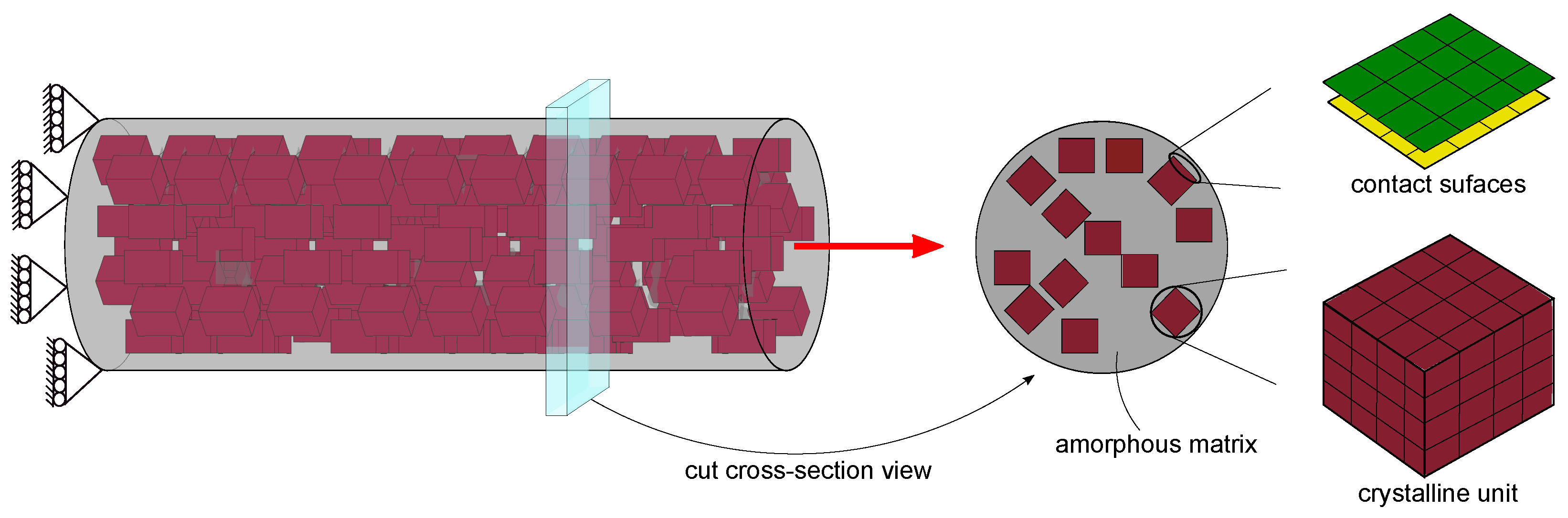
Figure 1. Illustrative representation of the spider dragline silk fiber architecture, highlighting the catching spiral silk (dotted black line), and the much dragline silk. Dragline silk fibers are mainly constituted of alanine-rich stiff and strong nano-crystals of β -sheets in the glycine-rich randomly disordered peptide chains.
Jcs 06 00095 g001
Figure 2. Finite element 3D model of dragline silk fiber (with fixed boundary conditions at one end and pulled condition at another end) on the left, and a cross-sectional view on the right. It is a cylindrical model with solid crystal blocks (red) randomly distributed in the amorphous phase (gray). The crystalline units are connected to the amorphous component along the fiber axis’s direction; however, in the lateral direction (perpendicular to the fiber axis) are surfaces of the crystals (yellow) in contact with surfaces of the amorphous phase (green).
Jcs 06 00095 g002
Figure 3. Tensile stress–strain curve for the FE dragline silk models from the spider Araneus diadematus for 0.4 m/s pulling velocity. The black line is the average of the stress–strain curves of the different 3D fiber models (differing in their random arrangement of the crystal units). The gray shaded area indicates the variation. The stress ( σ ) is defined as the resistance force per unit cross-sectional area of the silk fiber model. The strain ( ϵ ) is the ratio of change in silk fiber length to its initial length. The fiber model reached the highest point, which is defined as a breaking point, and the associated stress and strain values are the strength ( σ m a x ) and extensibility ( ϵ m a x ), respectively. The stress–strain curve’s initial slope (the elastic limit) can be used to measure Young’s modulus (E i n i t ). After yield point, the slope of the stress–strain curve is assigned as post-yield stiffness (E p o s t ). The material’s toughness can be defined as the area under the stress–strain curve.
Jcs 06 00095 g003
Figure 4. Schematic representation of the movement of crystalline units in the fiber model during loading.
Jcs 06 00095 g004
Figure 5. Influences of pulling speed on the mechanical properties of the dragline fiber model. Depicted here are variations in the properties, such as yield stress (a), yield strain (b), breaking stress (c) and breaking strain (d) with respect to velocity. Refer to the caption of Figure 3 for the definitions of the parameters mentioned above. Each data point stands for the average with standard errors taken from four different silk fiber random arrangement models.
Jcs 06 00095 g005
Figure 6. Depicted here are the variations in post-stiffness modulus and fiber diameter (a), and breaking energy (b), with respect to velocity. Each data point stands for an average with standard error taken from four different silk fiber random arrangement models.
Jcs 06 00095 g006
Figure 7. Hysteresis plots for the dragline fiber model of Araneus diadematus. (a) Individual loading-unloading cycles (the model was loaded to different levels of strain and unloaded) were performed to obtain hysteresis plots with loading speed of 0.4 m/s. (b) Cycle 4: An elongation along the axial direction of the fiber model of 21% of the original length. The energy dissipation in the fiber model is defined as the area between loading and unloading (yellow). Moreover, the area below the unloading curve (shaded area) represents the elastically stored energy.
Jcs 06 00095 g007
Table 1. Key structural components of Araneus diadematus dragline silk and their mechanical behavior from all-atom simulations to FEM simulations.
Structural ComponentMechanical Behavior aDescription b
crystalline unitirreversible deformationcrystal cubes are randomly
(plastic kinematic material)distributed with 25% vol.
amorphous phaserate-dependent deformationfilled the remaining space
(viscoelastic material)in the model
crystalline-amorphousviscous frictionlubricated film of 2D shell
interface(surface to surface contact)elements of the null material
a The mechanical behaviors of the crystalline unit [33], the amorphous phase [34] and the crystalline - amorphous interface [35] are from our previous work. b See also Figure 2 for the finite element modeling of components in 3D fiber model.
Table 2. Comparison of mechanical properties observed through 3D fiber model simulations and experimental data.
Mechanical Properties3D Fiber ModelExperimental Data a
ultimate Strength, σ m a x  (GPa)0.50–0.670.65–1.61
extensibility, ϵ m a x 0.32–0.360.23–0.45
initial stiffness, E i n i t  (GPa)6.5–8.13.8–10.0
post-yield stiffness, E p o s t  (GPa)1.1–1.71.5–5.1
toughness (MJ/m 3 )101–135120–225
hysteresis (%)70–7465–70.2
a The experimental data for Araneus diadematus dragline silk from [2,4,44,46,47].
Publisher’s Note: MDPI stays neutral with regard to jurisdictional claims in published maps and institutional affiliations.

