Article

Micromechanical Approach to Predict Mechanical Properties of Particulate-Dispersed Composites with Dissimilar Interfacial Phases

1
Department of Mechanical Engineering, Shizuoka University, Hamamatsu 432-8561, Japan
2
Graduate School of Engineering, Shizuoka University, Hamamatsu 432-8561, Japan
*
Author to whom correspondence should be addressed.
J. Compos. Sci. 2022, 6(12), 356; https://doi.org/10.3390/jcs6120356
Submission received: 29 September 2022 / Revised: 22 October 2022 / Accepted: 18 November 2022 / Published: 22 November 2022
(This article belongs to the Special Issue Characterization and Modelling of Composites, Volume III)

Abstract

:
The mechanical properties of composites are affected by their constituents. For the development of high-performance composites, it is expected that a technique will be developed which can predict the mechanical properties of composites based on the mechanical properties of their constituents. This study developed a technique based on a micromechanical approach to predict the mechanical properties of composites with interfacial phases between reinforcements and matrix. A double-inclusion model (Hori and Nemat-Nasser, 1993) is effective for the solution of such problems, of which the validity remains unclear. Problems with a particle surrounded by an interfacial phase embedded in an infinite body were calculated via the model and finite element analysis to verify the model. It was found that the macroscopic average stress of the double inclusion could be accurately solved by the model, although the microscopic stress of each phase could not be calculated with high accuracy. Therefore, a micromechanical approach based on the model was formulated and applied to particulate-dispersed composites consisting of zirconia and titanium, and fabricated by spark plasma sintering, in which Ti oxides were created along the interface between zirconia and titanium. As a result, the elastic-plastic stress–strain curves of the composites could be predicted. The approach can investigate the mechanical properties of composites with various shapes of reinforcement surrounded by dissimilar materials in a matrix. It can be concluded that the approach is promising for the development of composites with an excellent mechanical performance.

1. Introduction

To achieve mechanical performance superior to that possible with monolithic materials, composites and functionally graded materials (FGMs) have been developed. The matrices and reinforcements of these materials can be made of metals, ceramics, and plastics, depending on the application. Composites consisting of ceramics and metals are of interest because they may be anticipated to possess conflicting characteristics. Recently, biocompatible composites and FGMs have been explored for applications in implants, because they need to withstand severe loading in vivo. A wide range of properties are necessary for implant materials: high strength, high toughness, high hardness, high wear-resistance, and low stiffness, for mechanical properties, and bioinertness or bioactivity and non-toxicity, for chemical properties. To achieve these characteristics, titanium (Ti) and its alloys, stainless steels, and other biocompatible metals have been used, while among non-metals, partially stabilized zirconia (PSZ), alumina, hydroxyapatite (HA), and other biocompatible ceramics have been used [1,2,3,4,5]. To achieve the desired characteristics for implants, the development of composites consisting of biocompatible metals and ceramics has been pursued [6,7,8]. As the atomic bonding in ceramics is very different from that of metals, ceramic-metal composites have been fabricated by bonding melted metals with solid ceramics or by solid-state bonding of metals with ceramics. In particular, powder metallurgy (PM) has been often used to give more freedom in the choice of the materials, shapes, and arrangement of reinforcement materials. Several candidates for implant materials have been fabricated via PM [9,10,11,12,13]. We also fabricated biocompatible composites and FGMs using the biocompatible metals titanium and zirconium and biocompatible ceramics HA, alumina, and PSZ via hot pressing (HP) and spark plasma sintering (SPS) [14,15,16,17,18,19]. Among these material combinations, the combination of PSZ and Ti exhibited better mechanical properties compared with the others. However, interphase compounds such as Ti oxides were created during sintering because Zr and O atoms in the PSZ phase would diffuse into the Ti phase [20,21,22], as shown in Figure 1, resulting in the fabrication of three-phase particulate-dispersed composites. Figure 2 shows the mechanical performance of the composites, and indicates that all the composites exhibited brittleness and that their elastic properties could not be predicted by the rule of mixture. Their mechanical performance tended to be lower than expected, due to the presence of reaction phases, and we concluded that such phases were bound to be formed when the composites were made by the sintering of PSZ and Ti powders. Fernandez-Garcia et al. [23,24] also demonstrated the same results. Hence, it is necessary to evaluate the mechanical performance of multi-phase composites, and a micromechanical approach is useful for the evaluation. Hori and Nemat-Nasser [25] proposed a method to predict the stress state of a double inclusion in an infinite medium, based on the Mori-Tanaka mean-field concept [26] and Eshelby’s equivalent inclusion method [27] (the so-called double-inclusion model, DIM). Furthermore, they extended DIM to the prediction of the mechanical properties of multi-phase composites. DIM has successfully predicted the mechanical properties of several composites [28,29,30]. However, the accuracy of DIM remains unclear. If DIM can accurately calculate the stress state of a composite, it can be used to predict mechanical properties and to propose appropriate composites with superior mechanical properties.
This study aimed to investigate a micromechanical approach based on DIM, to predict the mechanical properties of three-phase composites. As an example, the model was applied to PSZ-Ti composites in which a Ti oxide surrounded the PSZ phase dispersed in the Ti matrix. A finite element analysis (FEA) of a model in which one PSZ particle is surrounded with Ti oxide in a Ti matrix was also performed. The microscopic stress of each phase calculated via FEA was compared with that determined via DIM, to examine its validity. Following this, the Young’s moduli of the PSZ-Ti composites with various volume fractions of Ti were solved via DIM, and compared with experimental results. The compositions of composites consisting of Ti, Ti oxide, and PSZ were estimated from a mechanical viewpoint. The stress–strain relations of the composites were also investigated.

2. Double-Inclusion Model and Its Accuracy

As a first step to develop a micromechanical approach able to predict the mechanical properties of particulate-dispersed composites with a reaction phase as shown in Figure 3, the accuracy of DIM was evaluated. Note that the reaction phase was actually identified as Ti oxide (Ti2O) or a mixed oxide (Ti2ZrO), etc. [14,15,16]. The reaction phase was assumed to be Ti oxide of Ti2O for the sake of simplicity in this study. Although DIM has been re-formulated in other equation forms by several researchers [31,32], the original DIM proposed by Hori and Nemat-Nasser [25] was used to characterize the mechanical properties of the composites in this study. In this section, the original DIM is firstly explained, and then the results solved via DIM are compared with those calculated via FEA.

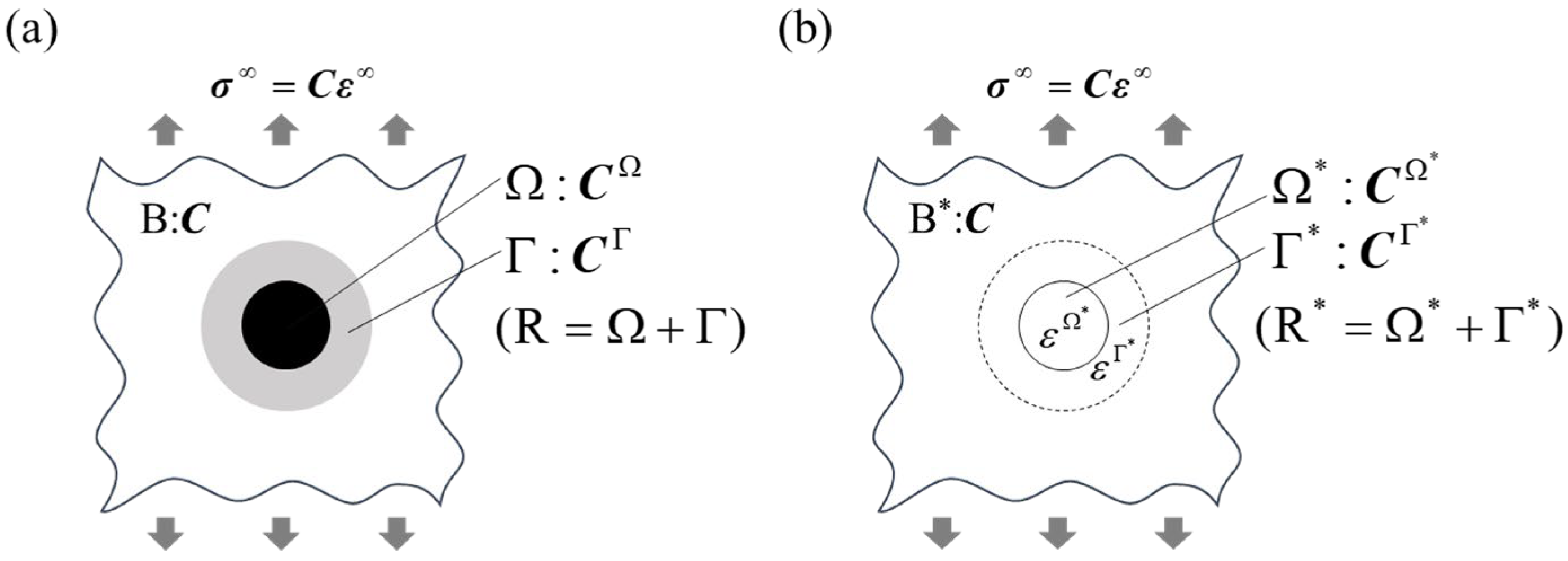
2.1. Double-Inclusion Model

Figure 4a shows a schematic of a double inclusion in an infinite medium subjected to tensile remote-stress σ in the vertical direction. An Ω phase is surrounded by a Γ phase, and they are embedded in an infinite medium, B phase. Additionally, an R phase denotes the sum of Ω and Γ phases: R = Ω + Γ. The stiffness of the B phase is simply denoted by C, and the stiffnesses of the Ω and G phases are denoted CΩ and CΓ, respectively. The stress and strain of each phase are denoted by σ and ε with the superscript corresponding to the phase, similar to the notation for stiffness. Note that the Ti2O phase would be formed due to oxygen diffusion from the PSZ phase into the Ti phase [20,21,22], and the Ω, Γ, and B phases are considered to be a PSZ particle, Ti2O around the particle, and the Ti matrix. When remote stress is applied, DIM is useful for solving the stress of each phase. In DIM, the Ω and Γ phases with stiffnesses CΩ and CΓ are replaced by the Ω* and Γ* phases with stiffness C, which is that of the matrix with eigenstrains of ε Ω * and ε Γ * , respectively: Figure 4b shows the equivalent problem to Figure 4a. According to this formulation, the stresses and strains of the Ω and Γ phases are calculated via DIM.
The microscopic average stresses of the Ω and Γ phases, which are denoted as σ Ω and σ Γ , respectively, are given by
σ Ω = C [ I + Δ S Φ Γ + ( S Ω I ) Φ Ω ] ε ,
σ Γ = C [ I + ( S R I f 1 f Δ S ) Φ Γ + f 1 f Δ S Φ Ω ] ε ,
where I is the identity matrix. The tensors SΩ, SΓ, and SR are the Eshelby tensors of the Ω, Γ, and R phases, respectively. The tensor ΔS is defined as SRSΓ. The volume fraction f is given by the volume of the Ω phase divided by the volume of the R phase: f = Ω / R. The relationship between remote stress and strain is given by
σ = C ε .
The tensors Φ Γ and Φ Ω are given by the following equations,
Φ Ω = [ ( S Ω + E 1 ) + Δ S ( S Ω f 1 f Δ S + E 2 ) 1 ( S Ω f 1 f Δ S + E 1 ) ] 1 ,  
Φ Γ = [ Δ S + ( S + E 1 ) + ( S Ω f 1 f Δ S + E 1 ) 1 ( S Ω f 1 f Δ S + E 2 ) ] 1 ,  
where E 1 = ( C Ω C ) 1 C and E 2 = ( C Γ C ) 1 C . In the materials targeted in this study, the reaction phase is assumed to be formed around a particle, and the Ω and Γ phases are concentric spheres, as shown in the figure. Therefore, the tensors SΩ and SΓ coincide, and the tensor ΔS becomes null. Hence, Equations (1) and (2) are given by
σ Ω = C [ I ( S Ω I ) { S Ω + ( C Ω C ) 1 C } 1 ] ε ,
σ Γ = C [ I ( S Ω I ) { S Ω + ( C Γ C ) 1 C } 1 ] ε .  
According to these equations, the average stress in each phase is constant, irrespective of the volume fraction, f. The average stress of the R phase is given by the volume average of the stresses in the Ω and Γ phases, and is given by the rule of mixture,
σ R = σ Ω f + σ Γ ( 1 f )   .

2.2. Validation of Double-Inclusion Model

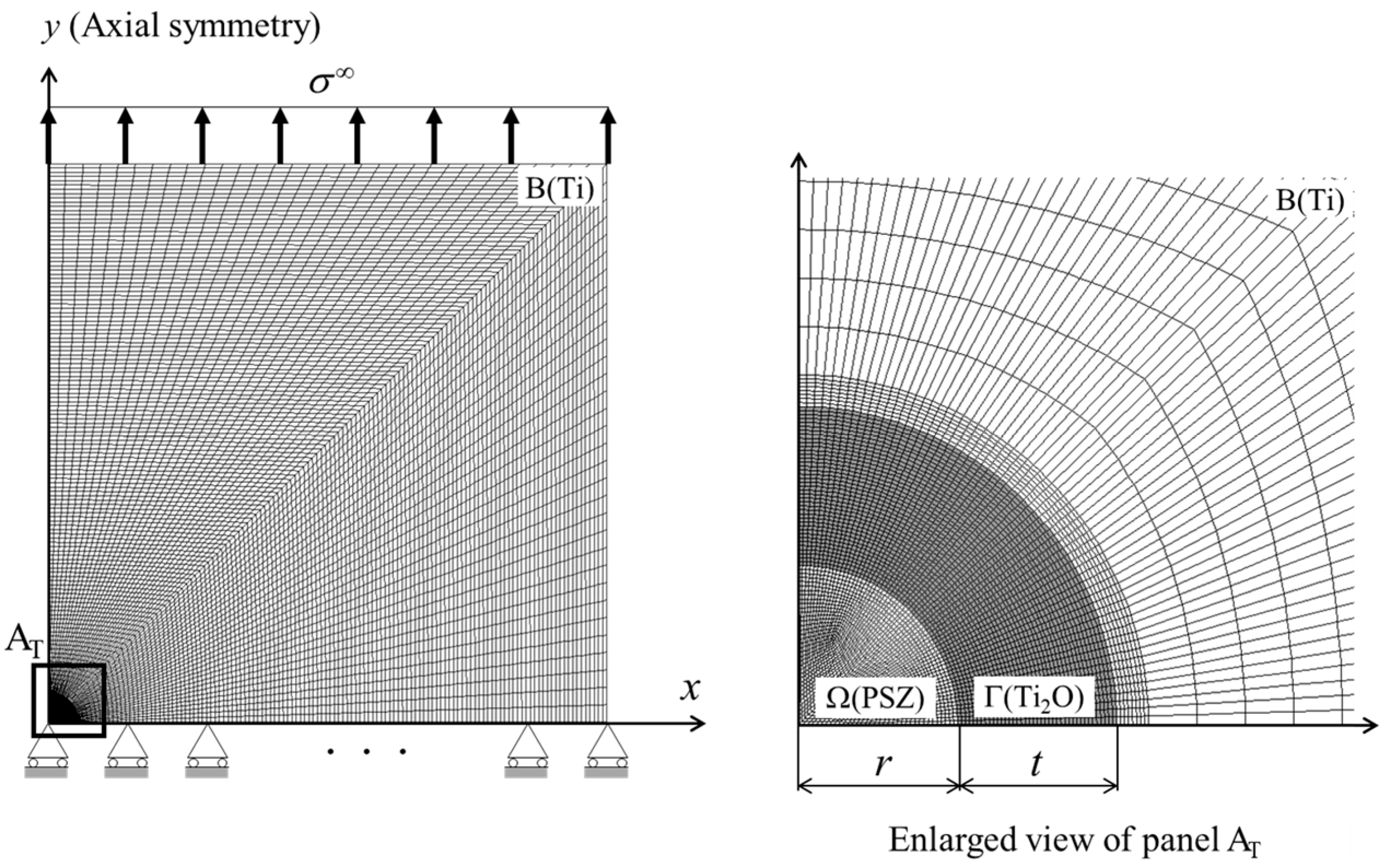
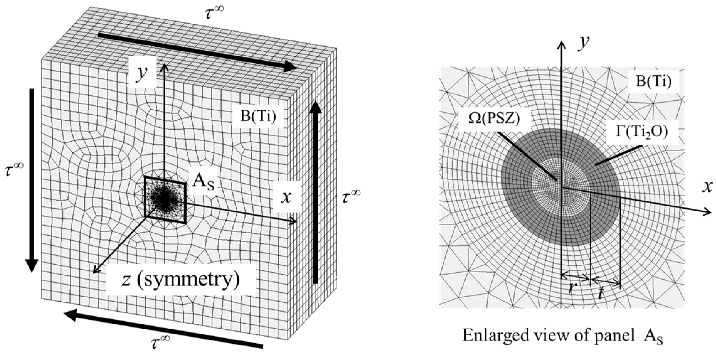
2.2.1. Finite Element Analysis

Although DIM can analytically calculate the microscopic average stress of each phase of double inclusions, as mentioned above, its accuracy remains unclear. FEA was performed on a single double-inclusion, with the Ω and Γ phases embedded in the B phase subjected to remote stress σ in the vertical direction, as shown in Figure 5. Axial symmetry was applied to the y axis, and a one-quarter model was calculated to deal with a concentric spherical double-inclusion. Note that meshes cannot be infinitely generated, and this study performed calculations for a double inclusion embedded in a cylindrical body that was sufficiently large compared to the double inclusion. In this case, the radius of the Ω phase was set at 10 µm, while the length of one side of the model was set at 400 µm. Comparing this to Figure 3, the Ω, Γ, and B phases are considered to be the PSZ, Ti2O, and Ti phases, respectively, and their elastic properties are tabulated in Table 1. The elastic moduli of Ti and PSZ were determined based on bend testing [15], and those of Ti oxide were determined from [33,34]. Note that these values were rounded from the experimental results for simplicity in this section, while the actual values were used in Section 3 to compare the analytical results with the experimental results. The average stresses of the Ω, Γ, and R phases with various thicknesses of Ti oxide t/r were calculated via FEA and DIM, and these stresses were compared. These analyses were conducted using the general-purpose software ANSYS.

2.2.2. Results and Discussion for Assessing Validity of Double-Inclusion Model

Figure 6 shows the distribution of normalized stress σ y / σ near a double inclusion with thickness t/r of 1.0. The stress in the Ω phase is uniform, while the stress distributes non-uniformly in the Γ phase; in particular, the stress concentrates in the Γ phase near the interface of the Ω phase at the x axis. In contrast, the stress in the B phase becomes lower near the interface of the Γ phase at the x axis.
Figure 7 shows the microscopic average stresses of the Ω and Γ phases with various thicknesses of the Γ phase. The average stress via FEM was calculated as the volume average of the stresses of all elements in each phase. In FEA, the case of only the Ω (Γ) phase embedded in the B phase was also analyzed, and their stresses were also plotted. The average stress σ y of each phase was normalized by the remote stress, σ . The stress of each phase decreases with increasing thickness, and the stress of the Γ phase is higher than that of the Ω phase, irrespective of thickness. As mentioned in Section 2.1, the average stresses of the Ω and Γ phases are constant, irrespective of the volume fraction, f. As for the Γ phase, the stress obtained via FEA is higher than that via DIM, but as the thickness decreases, the stress via FEA asymptotically approaches that obtained via DIM. Moreover, the stresses obtained via FEA and DIM are almost the same when only the Γ phase is embedded in the B phase. The opposite trend is observed for the Ω phase: the stresses obtained via FEA and DIM are almost the same when only the Ω phase is embedded in the B phase. In this case, the stress via FEA decreases with increasing thickness, and converges to a certain value.
Figure 8 shows the results of the average normal stresses of the R (=Ω + Γ) phase with various thicknesses of the Γ phase calculated via FEA and DIM. When the thickness, t/r, is less than approximately 2, the stress calculated via FEM increases with increasing thickness, t/r. Then, the stress approaches a certain value. These results are the same for the DIM calculation.
The case in which a spherical double-inclusion in an infinite body is subjected to shear is demonstrated in Appendix A. The trends of the stress of each phase calculated via FEA and DIM for tension are almost the same for shear. Hence, it is concluded that the accuracy of the microscopic average stresses of the Ω and Γ phases calculated via DIM depends on the thickness of the Γ phase. This would be because the interaction between the Ω phase and the Γ phase is not evaluated correctly. On the other hand, DIM accurately calculates the macroscopic average stress of the R (=Ω + Γ) phase, irrespective of the thickness of the Γ phase. Considering the actual PSZ-Ti composites, DIM can calculate the average stress of reinforcement by a PSZ particle including the Ti2O phase, irrespective of the amount of Ti2O phase created during sintering; the DIM calculation is accurate enough to predict the macroscopic behavior of PSZ-Ti composites, irrespective of the loading condition.

3. Mechanical Evaluation of Three-Phase Composites

3.1. Modeling of Three-Phase Composite Based on Double-Inclusion Model

The previous section discussed the case of a single double-inclusion in an infinite body, and this section describes a composite in which many double inclusions are dispersed in an infinite matrix. Elastic-plastic deformation of the composites is considered to predict the experimental results [15]. Figure 9 shows a schematic of a composite consisting of double inclusions of the Ω phase (PSZ) and the Γ phase (Ti2O) in the B phase (Ti). Hori and Nemat-Nasser [25] demonstrated that the problem for the composites shown in Figure 9a is equivalent to the problem of a triple inclusion of Ω, Γ, and Γ2 phases in an infinite B phase, in which the stiffness of the Γ2 phase is the same as that of the B phase shown in Figure 9b. Furthermore, the problem shown in Figure 9b is equivalent to the problem shown in Figure 9c, which is the same technique mentioned in the previous section: the Ω, Γ, and Γ2 phases with stiffnesses of CΩ, CΓ, and C Γ 2 (= C) are replaced by the Ω, Γ, and Γ2 phases with stiffness C with eigenstrain of ε Ω * , ε Γ * , and ε Γ 2 * , respectively. The phase with combined Ω, Γ, and Γ2 also denotes an R phase, and the phase with combined ε Ω * , ε Γ * , and ε Γ 2 * denotes an R* phase. For simplicity, the triple inclusion is also assumed to be a concentric sphere in this study, which is reasonable because the target is still particulate-dispersed composites consisting of PSZ and Ti.
The increment of average stress of each phase is given by
d σ Ω = C [ I + ( S Ω I ) Ψ Ω ] d ε ,  
d σ Γ = C [ I + ( S Ω I ) Ψ Γ ] d ε ,  
d σ Γ 2 = C [ I + ( S Ω I ) Ψ Γ 2 ] d ε = C d ε ,  
where the tensors Ψ Ω , Ψ Γ , and Ψ Γ 2 are the following:
Ψ Ω = [ ( C Ω C ) S + C ] 1 ( C Ω C ) ,  
Ψ Γ = [ ( C Γ C ) S + C ] 1 ( C Γ C ) ,
Ψ Γ 2 = [ ( C C ) S + C ] 1 ( C C ) = 0 .
In addition, the average strain increment of each phase is obtained by the following:
d ε Ω = ( I + S Ψ Ω ) d ε = C Ω 1 d σ Ω ,
d ε Γ = ( I + S Ψ Γ ) d ε = C Γ 1 d σ Γ ,
d ε Γ 2 = C 1 d σ Γ 2 = C 1 C d ε = d ε .
The increments of average stress and strain for the Ω, Γ, and Γ2 phases in the triple inclusion correspond to the increments of average stress and strain for the Ω, Γ, and B (matrix) phases in the three-phase composite. Therefore, the increments of average stress and strain in the matrix are as follows:
d σ m = d σ Γ 2 = C d ε ,
d ε m = d ε Γ 2 = d ε .
The remote-strain increment of the triple inclusion problem is related to the strain increment of the composite by the following:
d ε = ( I + S Φ R ) 1   d ε .  
Finally, the stress–strain relationship for the composite is given by
d σ = C [ I + ( S Ω I ) Φ R ] ( I + S Φ R ) 1 d ε ,  
where Φ R is defined as f Ω Ψ Ω + f Γ Ψ Γ , and the values of fΩ and fΓ are the volume fractions of the Ω and Γ phases, respectively. In this formulation, Ti and PSZ are considered to be the matrix and reinforcement, respectively, corresponding to a Ti-rich composite; in the formulation of PSZ-rich composites, Ti and PSZ are simply interchanged.
To analyze the elastic-plastic deformation of composites, the Ω and Γ phases are assumed to be isotropic elastic, while the B phase (matrix) is isotropic elastic-plastic. This means that the Ω, Γ, and B phases are considered to be PSZ, Ti2O, and Ti, respectively. The equivalent stress-equivalent strain relationship of the matrix is set to be expressed by the Ramberg–Osgood equation [35]
ε 0 e = σ 0 e E 0 + λ σ 0 0 E 0 ( σ 0 e σ 0 0 ) 1 / n ,  
where σ 0 e , ε 0 e , E0, σ 0 0 , n, and λ are equivalent stress, equivalent strain, Young’s modulus, yield stress, strain-hardening coefficient, and material constant, respectively. The analysis of elastic-plastic deformation of the composite requires the equivalent stress in the matrix of the composite. However, the microscopic stress of the matrix is non-uniformly distributed, due to the load-bearing of reinforcing particles, as shown in Figure 6. In this study, the Tohgo–Weng energy approach [36] was used to calculate the average stresses in the matrix, taking into account the non-uniform deformation in the composite. The initial equivalent stress of the composite under elastic deformation is given by
( σ 0 e ) 2 = 3 μ 0 1 f Ω f Γ ( 2 U f Ω σ Ω ε Ω f Γ σ Γ ε Γ ) 3 μ 0 κ 0 ( σ 0 m ) 2 ,
where σ 0 m is the average hydrostatic stress of the matrix, μ 0 and κ 0 are the shear modulus and bulk modulus of the matrix, respectively, and U is the energy of composite per unit volume and given by
U = 1 2   σ   ε .  
The equivalent stress before incremental deformation is described as σ 0 e , and the equivalent stress after incremental deformation is described as σ 0 e   + d σ 0 e . The equivalent stress increment, d σ 0 e , is given by the following:
d σ 0 e = 3 μ 0 σ 0 e ( 1 f Ω f Γ ) ( d U f Ω σ Ω d ε Ω f Γ σ Γ d ε Γ ) 3 μ 0 σ 0 e κ 0 σ 0 m d σ 0 m ,  
where d U is the incremental energy of composite per unit volume,
d U = σ   d ε  
In the incremental analysis, the equivalent stress, σ 0 e , of the matrix before incremental deformation is known, and the equivalent stress after incremental deformation can be determined using the above equation.

3.2. Application of Double-Inclusion Model for PSZ-Ti Composites

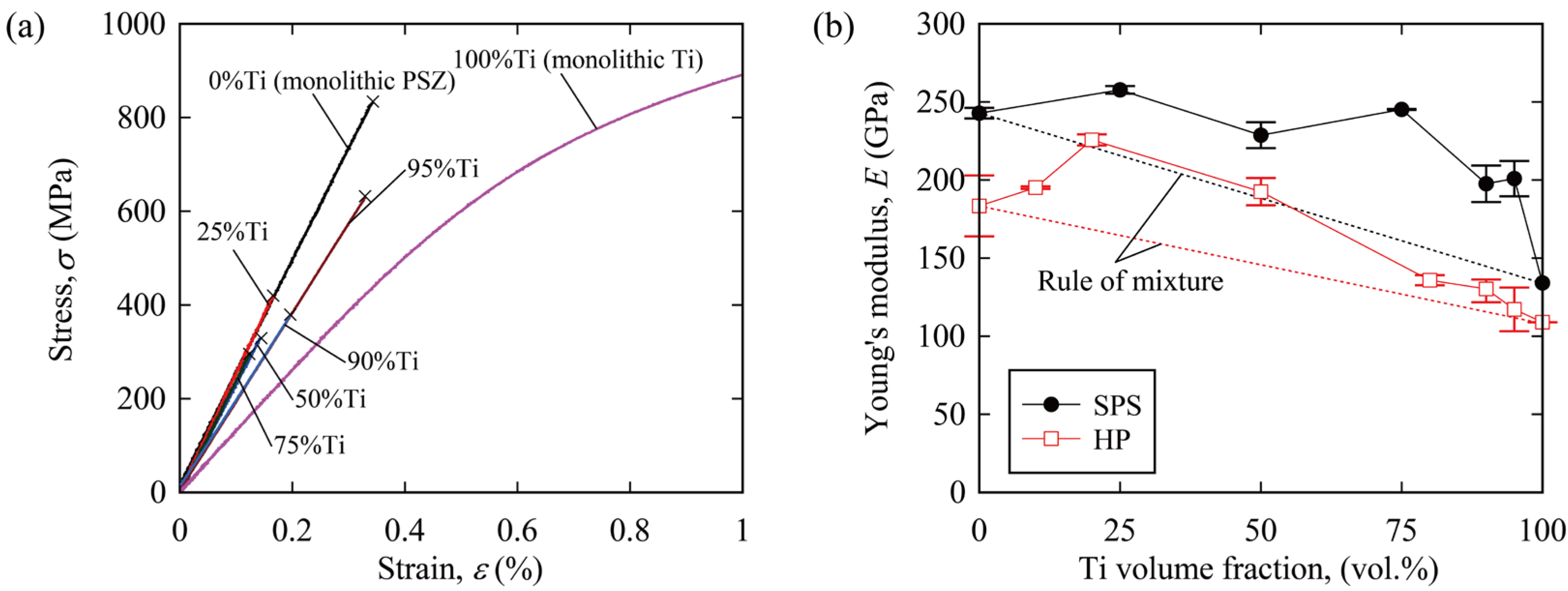
3.2.1. Elastic Properties of PSZ-Ti Composites

The Young’s moduli of the PSZ-Ti composites were calculated by varying their phase compositions, and then the phase compositions of the composites fabricated via SPS [15] were estimated, based on the relationship between the Young’s modulus and phase composition. In this calculation, the elastic properties of Ti, Ti2O, and PSZ are also used in Table 2. Figure 10 shows the Young’s modulus as a function of the volume fraction of Ti added. Note that part of the added Ti was oxidized to Ti2O, etc., during sintering, and the horizontal axis indicates the volume fraction of Ti + Ti2O. The Young’s modulus in the vertical axis was normalized by that of the Ti phase, Em. The Young’s modulus of the composites increases with an increase in the volume fraction of Ti2O. In this figure, the experimental results of the Young’s modulus as a function of the Ti volume fraction of the PSZ-Ti composites fabricated via SPS are also plotted, which are the same as in Figure 2. By comparing the Young’s moduli of the composites fabricated via SPS with those calculated via DIM, the volume fraction of Ti2O created during sintering was estimated. Figure 11 shows the estimated constituents of the composites Ti, Ti2O, and PSZ. While single phases of Ti and PSZ are present in monolithic Ti and PSZ, respectively, the three phases Ti, Ti2O, and PSZ are present in the composites. If the volume fraction of Ti + Ti2O is less than 80%, the fraction of Ti2O is larger than that of Ti, indicating that most of the added Ti is oxidized to Ti2O. If the volume fraction of Ti + Ti2O is more than 80%, the fraction of the Ti phase drastically increases. This means that the metallic Ti phase would remain after sintering. As for the PSZ-Ti composites fabricated via HP [14], the trend of Ti oxide formation is almost the same as for the composites fabricated via SPS.

3.2.2. Elastic-Plastic Properties of PSZ-Ti Composites

Based on the incremental elastic-plastic constitutive model using DIM formulated in Section 3.1, the stress–strain relations of the PSZ-Ti composites fabricated via SPS are discussed. The elastic properties of Ti, Ti2O, and PSZ in Table 2 were used, and the elastic-plastic properties of Ti were set at σ 0 0 = 268.2   MPa , n = 0.183, and λ = 0.00241. Note that these values were obtained from the stress–strain curve of monolithic Ti, which is shown in Figure 1. Analyses were performed for various volume fractions of the Ti + Ti2O phase: 75 vol.%, 50 vol.%, 25 vol.%, 10 vol.%, and 5 vol.%. Figure 12 shows the predicted stress–strain curves of Ti-rich and PSZ-rich composites with various volume fractions of Ti/(Ti+Ti2O). If Ti/(Ti+Ti2O) is null, the added Ti is fully oxidized, and no metallic Ti phase is present in the composite. On the other hand, if Ti/(Ti+Ti2O) is 100%, no oxidation occurs during sintering, and the added metallic Ti remains as it is. In addition, the experimental results from the bending stress–strain curves shown in Figure 2a are added in this figure. In a PSZ-rich composite (25%Ti), even if Ti/(Ti+Ti2O) is varied, the volume fraction of the Ti-related phase is small, so the influence of Ti oxides on the deformation characteristics is also small. The stress–strain curve obtained via the experiment and that obtained by DIM for a volume fraction Ti/(Ti+Ti2O) of 0% via DIM coincide. Hence, in PSZ-rich composites, no metallic Ti phase was present, and the composite deformed in a brittle manner, not a ductile manner. In contrast, in the Ti-rich composite, the volume fraction of Ti oxidation strongly affects the elastic-plastic deformation characteristics. If the fraction of Ti2O is large, the composites exhibit greater stiffness, because the stiffness of Ti2O is higher than that of metallic Ti. Moreover, the nonlinearity of the stress–strain curve becomes larger as the fraction of Ti2O increases. Comparing the result obtained by DIM with the experimental result, non-linearity due to plastic deformation should appear in the stress–strain curve, but the composite fractured at a much lower stress before plastic deformation occurred. This would be because an unstable fracture occurred from a small defect in the brittle phases of the PSZ phase and/or the Ti oxide phase created during sintering.
For the sake of simplicity in this study, the Ti and PSZ phases are assumed to be the matrix and reinforcement, respectively, irrespective of the volume fraction of Ti/PSZ. This assumption is correct for the Ti-rich composites. However, this may be not suitable for the PSZ-rich composites, because Ti-related phases such as metallic Ti and Ti oxide would be dispersed in a PSZ matrix. As mentioned in Section 3.1, calculations can be performed simply by interchanging the properties of PSZ and Ti for the PSZ-rich composites. Although it must be possible to perform calculations with the PSZ and Ti phases interchanged, this study did not deal exactly with the Ti phase, due to the accuracy of the DIM calculations; thus, the microscopic average stress of each phase could not be calculated accurately, as shown in Figure 7 and in A4. If DIM can be improved so that the microscopic average stress of each phase can be accurately analyzed, the PSZ-rich composites will be further studied in detail. In addition, from the viewpoint of calculation accuracy, the elastic properties of Ti oxide should be clarified. As mentioned in Section 2.1, the Ti phase is chemically reacted with the constituent elements of PSZ to form Ti2O, Ti2ZrO, etc., and the Ti2O was described in this paper as a representative of those phases. At this moment, the mechanical properties of such phases remain unknown, and those of Ti2O obtained from [33,34] are used in this study. It is expected that clarification of the mechanical properties of each phase and the improvement of DIM to accurately calculate the microscopic average stress and strain of each phase will enable more detailed evaluation of the mechanical properties of the composites.
Sintering is commonly used to fabricate metal matrix composites and ceramic matrix composites. Densification progresses with atomic diffusion during sintering, and a diffusion layer is formed along the interface between the reinforcement and matrix. The mechanical properties of the composites have conventionally been evaluated based on the mechanical properties of the reinforcement and matrix only. However, the diffusion layer must affect the mechanical properties of the sintered composites. Note that the geometry and properties of the diffusion layer would depend on the sintering conditions. Hence, the micromechanical approach developed in this study can evaluate the mechanical properties of such composites by considering not only the matrix and reinforcement, but also the diffusion layer. In this study, the approach was applied to the particulate-dispersed composites consisting of PSZ and Ti as an example, and its effectiveness was verified. In recent years, composites using reinforcements coated with functional materials have also been developed [37], and their mechanical properties would be predicted by the approach. It should be noted that the approach is versatile, because it can be applied to various composite materials, for example, long-fiber reinforced composites, by changing the Eshelby tensors. The approach was found to be useful in the development of high-performance composites because of its ability to predict the mechanical properties of three-phase composites, with high accuracy.

4. Conclusions

To predict the mechanical properties of composites with dissimilar interfacial phases between the reinforcements and the matrix, a micromechanical approach was developed, based on the double-inclusion model. The results obtained in this study are summarized as follows:
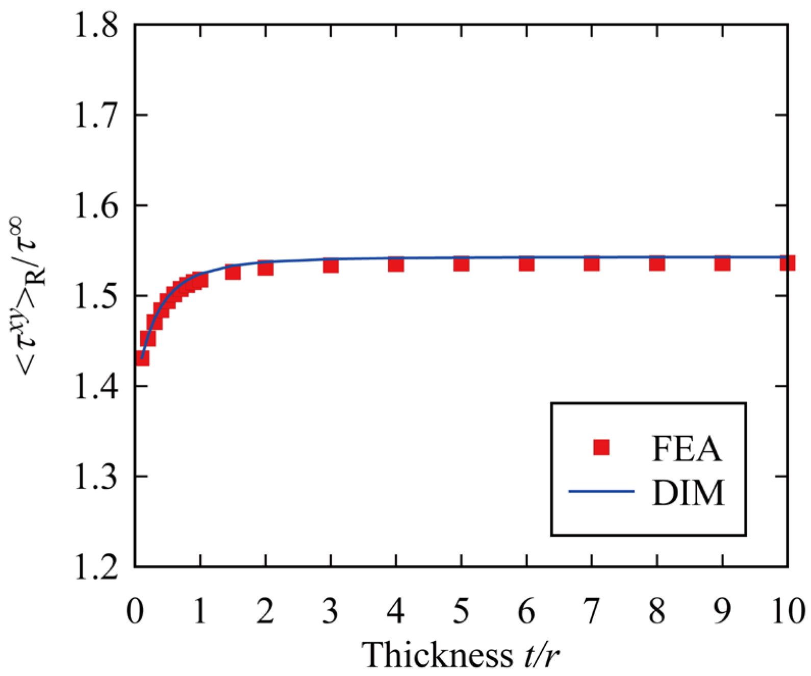
  • The double-inclusion model can accurately predict the macroscopic stress state in the composites. However, it is not possible for the double-inclusion model to accurately calculate the microscopic stress of each phase simultaneously.
  • The micromechanical approach was formulated. The approach can predict the elastic-plastic behavior of a composite in which reinforcements surrounded by dissimilar materials are placed in a matrix.
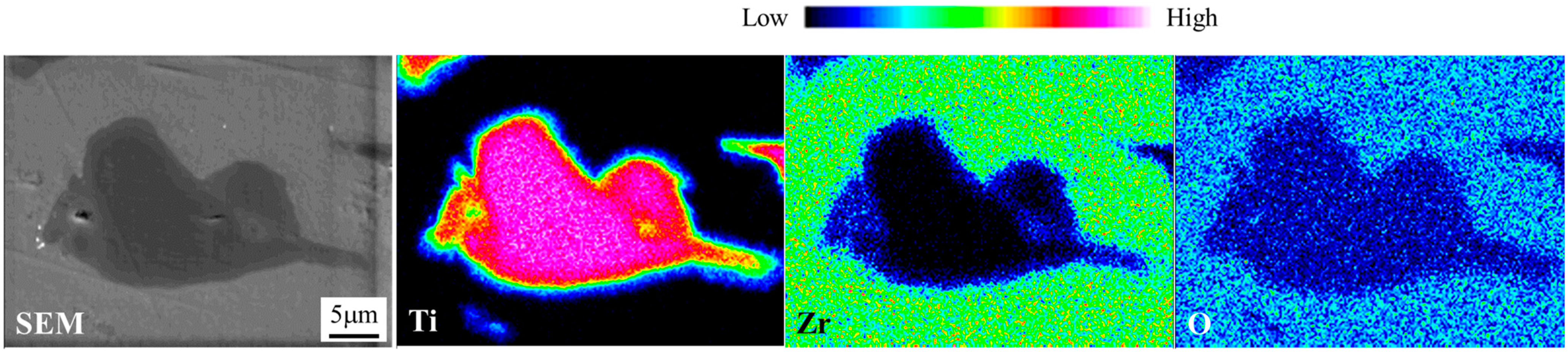
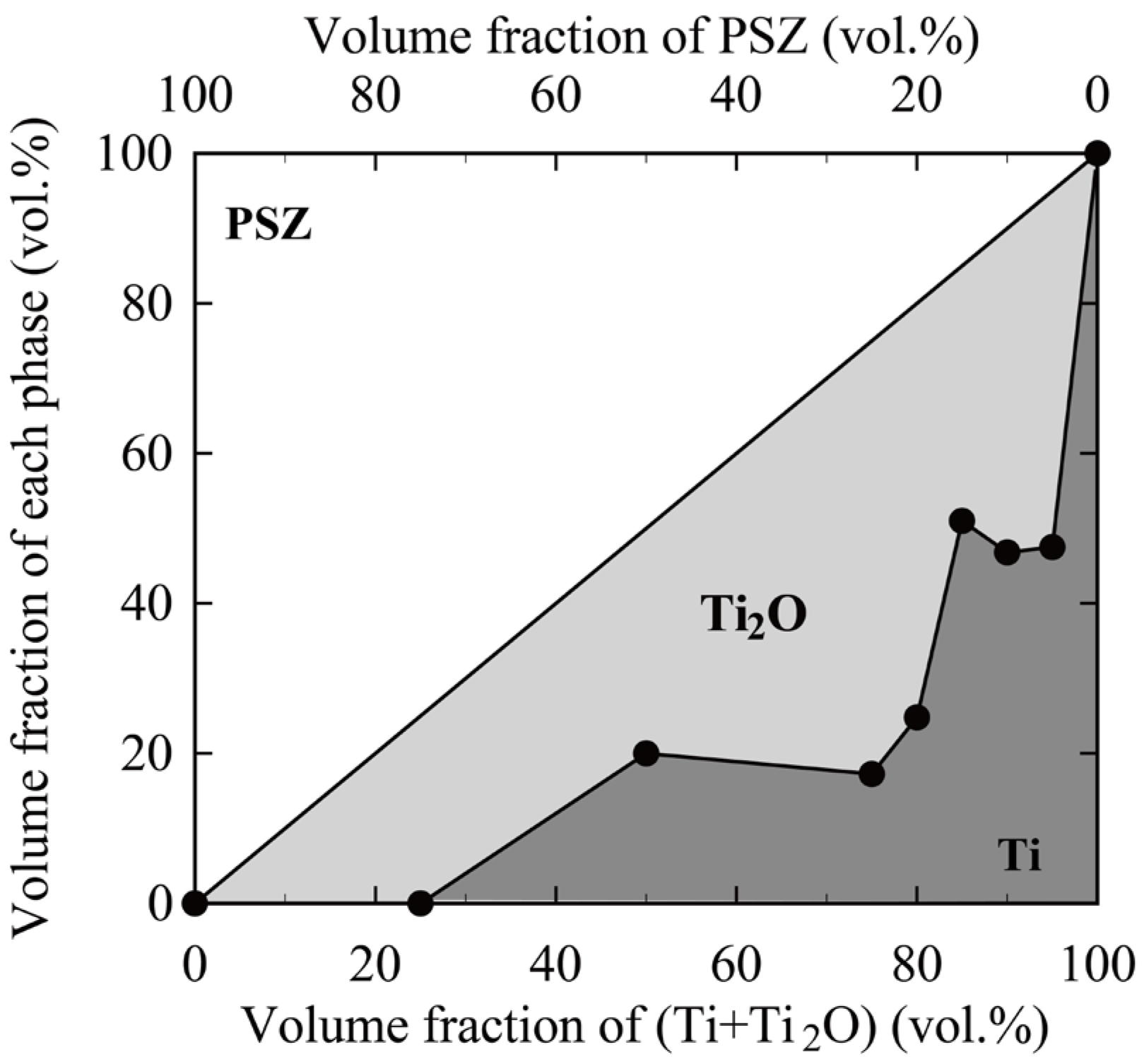
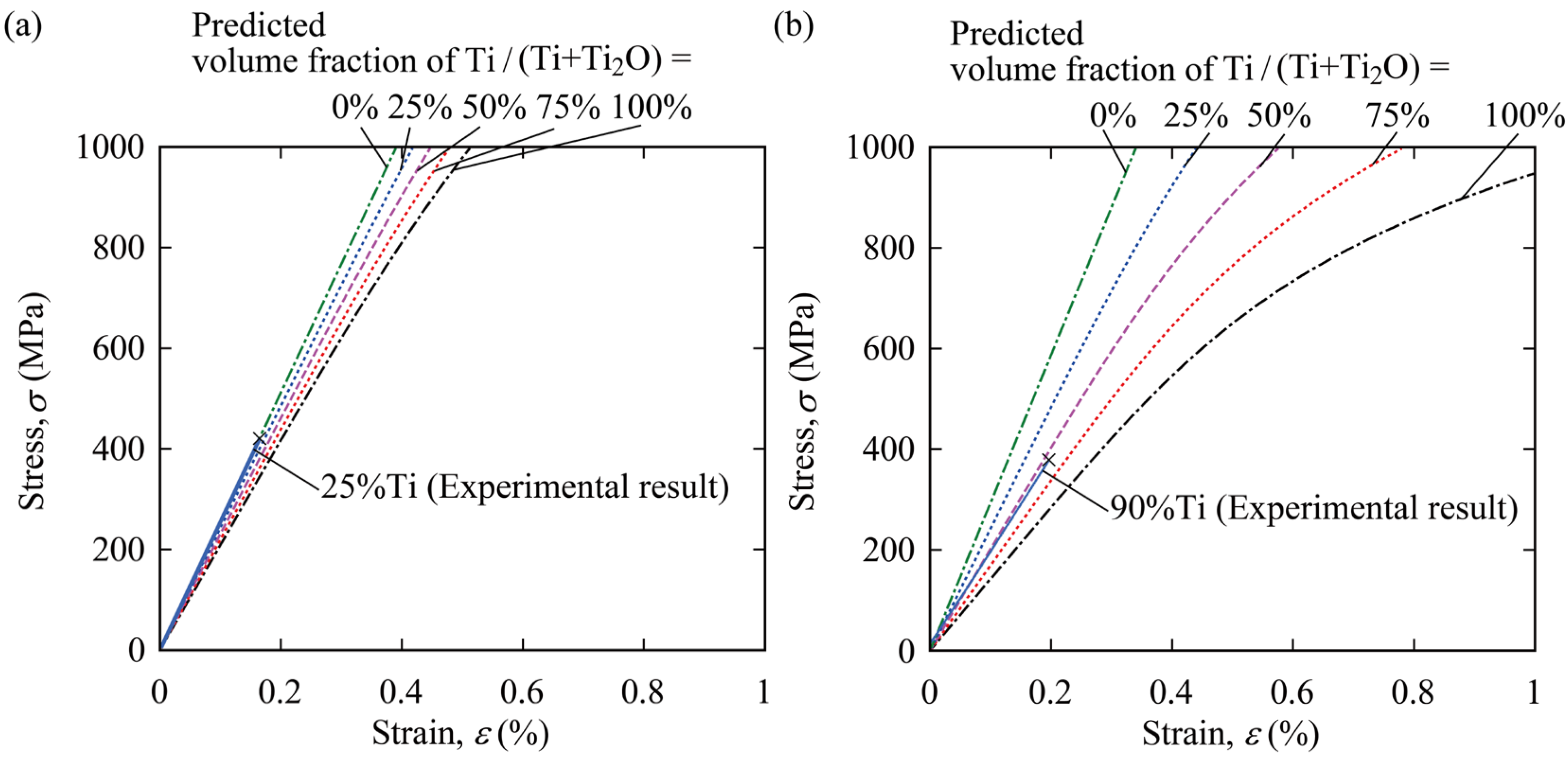
  • The micromechanical approach was applied to the PSZ-Ti composites fabricated via spark plasma sintering, in which Ti oxides were created between the Ti and PSZ phases. The volume fraction of the Ti oxides was mechanically estimated, and the elastic-plastic stress–strain relations of the composites could be predicted. The approach is found to be effective for accurately predicting the mechanical properties of sintered composites.

Author Contributions

Conceptualization, K.T.; methodology, T.F. and T.O.; validation, T.F., K.T., T.O. and Y.S.; formal analysis, T.F. and T.O.; investigation, K.T. and T.F.; resources, K.T.; data curation, T.F.; writing—original draft preparation, T.F.; writing—review and editing, T.F.; visualization, T.F.; project administration, K.T.; funding acquisition, K.T. All authors have read and agreed to the published version of the manuscript.

Funding

This work was supported by JSPS KAKENHI Grant Number (B)15H03891.

Institutional Review Board Statement

Not applicable.

Informed Consent Statement

Not applicable.

Data Availability Statement

The data presented in this study are available on request from the corresponding author.

Conflicts of Interest

The authors declare no conflict of interest.

Appendix A. Double Inclusion Subjected to Shear

To discuss the calculation accuracy of DIM, a double inclusion in an infinite body subjected to shear was analyzed. The stress distribution and microscopic average stress of each phase was calculated via DIM and FEA, similar to Section 2.2.
Figure A1 shows the calculation model for a concentric spherical double-inclusion in a cubic body which is sufficiently large, compared with the inclusion. The radius of the Ω phase was set at 10 µm, and the length of one side of the body was set at 800 µm. The Ω phase surrounded with the Γ phase was embedded in the B phase, and the remote shear-stress, τ , was applied to all four sides of the body. Due to symmetry, a half-model of this double-inclusion problem was solved with various thicknesses of the Γ phase t/r. It should be noted that the Ω, Γ, and B phases also correspond to PSZ, Ti2O, and the Ti matrix, respectively.
Figure A1. Finite element analysis of double inclusion subjected to shear loading.
Jcs 06 00356 g0a1
Figure A2 shows an example of the FEA result: the distribution of shear stress, τ xy , near a double inclusion with thickness t/r of 1.0, which is normalized by the τ . The stress distribution is uniform in the Ω phase, while the stress is distributed non-uniformly in the Γ and B phases, and the stress concentrates in some regions.
Figure A2. Distribution of shear stress τ xy in the vicinity of a double inclusion.
Jcs 06 00356 g0a2
Figure A3 shows the average shear stresses of the Ω and Γ phases as functions of the thickness t/r. The influence of thickness on average stress and the relationship between FEA and DIM are almost the same as in the case of the double inclusion in the infinite body subjected to remote normal stress; as for the DIM calculation, the average stress of each phase is constant, irrespective of the thickness. As for the FEA calculation, the stress of each phase decreased with increasing thickness, t/r. Comparing DIM to FEA, although the stress of the Γ phase obtained from FEA was higher than that from FEA when the Γ phase was thin, the stress from FEA asymptotically approached the stress from DIM with increasing thickness, t/r. In contrast, the stresses of the Ω phase obtained from FEA and DIM were almost the same when the Γ phase was very thin, whereas the difference between the stresses obtained by DIM and FEA became large with increasing thickness, t/r. Figure A4 shows the results of the average shear stresses of the R (=Ω + Γ) phase with various thicknesses, t/r, calculated via FEA and DIM. The trends of the relationship between the stress and the thickness obtained via DIM and FEA are almost the same: The stresses calculated increased with increasing thickness, t/r, and the stresses approached a certain value. These results related to the double inclusion subjected to shear must be the same as those subjected to tension, which was mentioned in Section 2.2.
Figure A3. Microscopic shear stresses of Ω and Γ phases with various thicknesses of the Γ phase. The microscopic average stress τ x y of each phase is normalized by the remote stress τ .
Jcs 06 00356 g0a3
Figure A4. Average shear stress of R phase (=Ω + Γ) with various thicknesses of the Γ phase. The microscopic average stress τ x y R is normalized by the remote stress τ .
Jcs 06 00356 g0a4
Hence, it was concluded that DIM can accurately calculate the macroscopic behavior of a composite with double inclusions, irrespective of loading condition, although the microscopic stresses cannot be accurately calculated, as they depend on the geometries of double inclusions.

References

  1. Niinomi, M. Mechanical properties of biomedical titanium alloys. Mater. Sci. Eng. A 1998, 243, 231–236. [Google Scholar] [CrossRef]
  2. Xiao, M.; Chen, Y.M.; Biao, M.N.; Zhang, X.D.; Yang, B.C. Bio-functionalization of biomedical metals. Mater. Sci. Eng. C 2017, 70, 1057–1070. [Google Scholar] [CrossRef]
  3. Javanbakht, M.; Salahinejad, E.; Hadianfard, M.J. The effect of sintering temperature on the structure and mechanical properties of medical-grade powder metallurgy stainless steels. Powder Technol. 2016, 289, 37–43. [Google Scholar] [CrossRef]
  4. Denry, I.; Kelly, J.R. State of the art of zirconia for dental applications. Dent. Mater. 2008, 24, 299–307. [Google Scholar] [CrossRef]
  5. Heimann, R.B. Silicon Nitride, a Close to Ideal Ceramic Material for Medical Application. Ceramics 2021, 4, 208–223. [Google Scholar] [CrossRef]
  6. Cook, W.E.; Manning, C.R., Jr.; Hurt, J.C.; Taylor, D.F. Ceramic metal composites for surgical implants. J. Biomed. Mater. Res. 1972, 6, 443–466. [Google Scholar] [CrossRef]
  7. Travitzky, N. Processing of ceramic-metal composites. Adv. Appl. Ceram. 2012, 111, 286–300. [Google Scholar] [CrossRef]
  8. Travitzky, N.; Fu, Z.; Knyazeva, A.; Janssen, R.; Nekludov, D.; Yin, X.; Greil, P. Reactive Synthesis of Ceramic-Metal Composites. Adv. Eng. Mater. 2018, 20, 1800324. [Google Scholar] [CrossRef]
  9. Rahmani, R.; Molan, K.; Brojan, M.; Prashanth, K.G.; Stopar, D. High virucidal potential of novel ceramic-metal composites fabricated via hybrid selective laser melting and spark plasma sintering routes. Int. J. Adv. Manuf. Technol. 2022, 120, 975–988. [Google Scholar] [CrossRef]
  10. Arifin, A.; Sulong, A.B.; Muhamad, N.; Syarif, J.; Ramli, M.I. Material processing of hydroxyapatite and titanium alloy (HA/Ti) composite as implant materials using powder metallurgy: A review. Mater. Des. 2014, 55, 165–175. [Google Scholar] [CrossRef]
  11. Rahmani, R.; Kamboj, N.; Brojan, M.; Antonov, M.; Prashanth, K.G. Hybrid metal-ceramic biomaterials fabricated through powder bed fusion and powder metallurgy for improved impact resistance of craniofacial implants. Materialia 2022, 24, 101465. [Google Scholar] [CrossRef]
  12. Mokhtari, S.; Eftekhari Yekta, B.; Marghussian, V.; Ahmadi, P.T. Synthesis and characterization of biodegradable AZ31/calcium phosphate glass composites for orthopedic applications. Adv. Compos. Hybrid Mater. 2022, 3, 390–401. [Google Scholar] [CrossRef]
  13. Ahmet, Y.; Ayhan, E.; Günnur, P. Characterization of egg shell powder-doped ceramic–metal composites. Open Chem. 2022, 20, 716–724. [Google Scholar]
  14. Fujii, T.; Tohgo, K.; Araki, H.; Wakazono, K.; Ishikura, M.; Shimamura, Y. Fabrication and strength evaluation of biocompatible ceramic-metal composite materials. J. Solid Mech. Mater. Eng. 2010, 4, 1699–1710. [Google Scholar] [CrossRef] [Green Version]
  15. Tohgo, K.; Fujii, T.; Harada, M.; Isono, H.; Shimamura, Y. Fabrication of PSZ-Ti composites by spark plasma sintering and their mechanical properties. Mater. Sci. Eng. A 2015, 621, 166–172. [Google Scholar] [CrossRef]
  16. Fujii, T.; Suzuki, M.; Tohgo, K.; Shimamura, Y. Spark plasma sintering of PSZ-Ti composites using ceramic-coated Ti powder to suppress sintering reaction. Metall. Mater. Trans. A 2021, 52, 1443–1452. [Google Scholar] [CrossRef]
  17. Fujii, T.; Tohgo, K.; Isono, H.; Shimamura, Y. Fabrication of a PSZ-Ti functionally graded material by spark plasma sintering and its fracture toughness. Mater. Sci. Eng. A 2017, 682, 656–663. [Google Scholar] [CrossRef]
  18. Fujii, T.; Tohgo, K.; Iwao, M.; Shimamura, Y. Fracture toughness distribution of alumina-titanium functionally graded materials fabricated by spark plasma sintering. J. Alloys Compd. 2018, 766, 1–11. [Google Scholar] [CrossRef]
  19. Fujii, T.; Tohgo, K.; Iwao, M.; Shimamura, Y. Fabrication of alumina-titanium composites by spark plasma sintering and their mechanical properties. J. Alloys Compd. 2018, 744, 759–768. [Google Scholar] [CrossRef]
  20. Fukui, Y.; Fujii, T.; Tohgo, K.; Shimamura, Y. Multi-physics simulation of oxygen diffusion in PSZ-Ti composites during spark plasma sintering process. Comput. Mater. Sci. 2014, 95, 24–34. [Google Scholar] [CrossRef]
  21. Shinohara, T.; Fujii, T.; Tohgo, K.; Shimamura, Y. Densification process in fabrication of PSZ-Ti composites by spark plasma sintering technique. Mater. Charact. 2017, 132, 230–238. [Google Scholar] [CrossRef]
  22. Fujii, T.; Togho, K.; Goto, K.; Shimamura, Y. Interfacial properties of bonded dissimilar materials fabricated via spark plasma sintering. Mater. Trans. 2021, 62, 1102–1108. [Google Scholar] [CrossRef]
  23. Fernandez-Garcia, E.; Gutierrez-Gonzalez, C.F.; Fernandez, A.; Torrecillas, R.; Lopez-Esteban, S. Processing and spark plasma sintering of zirconia/titanium cermets. Ceram. Int. 2013, 39, 6931–6936. [Google Scholar] [CrossRef]
  24. Fernandez-Garcia, E.; Gutierrez-Gonzalez, C.F.; Peretyagin, P.; Solis, W.; Lopez-Esteban, S.; Torrecillas, R.; Fernandez, A. Effect of yttria-titanium shell-core structured powder on strength and ageing of zirconia/titanium composites. Mat. Sci. Eng. A-Struct. 2015, 646, 96–100. [Google Scholar] [CrossRef]
  25. Hori, M.; Nemat-Nasser, S. Double-inclusion model and overall moduli of multi-phase composites. Mech. Mater. 1993, 14, 189–206. [Google Scholar] [CrossRef]
  26. Mori, T.; Tanaka, K. Average stress in matrix and average elastic energy of materials with misfitting inclusions. Acta Metall. 1973, 21, 571–574. [Google Scholar] [CrossRef]
  27. Eshelby, J.D. The determination of the elastic field of an ellipsoidal inclusion and related problems. Proc. Roy. Soc. Lond. A 1957, 241, 376–396. [Google Scholar]
  28. Jiang, Y.; Guo, W.; Yang, H. Numerical studies on the effective shear modulus of particle reinforced composites with an inhomogeneous inter-phase. Comput. Mater. Sci. 2008, 43, 724–731. [Google Scholar] [CrossRef]
  29. Vinyas, M.; Sunny, K.K.; Harursampath, D.; Nguyen-Thoi, T.; Loja, M.A.R. Influence of interphase on the multi-physics coupled frequency of three-phase smart magneto-electro-elastic composite plates. Compos. Struct. 2019, 226, 111254. [Google Scholar] [CrossRef]
  30. Araki, S.; Ono, H.; Saito, K. Approximate Analysis of Stress Fields in and around a Thin-Coated Fiber by Means of Double Inclusion Method. Theor. Appl. Mec. Jpn. 2002, 51, 75–90. [Google Scholar]
  31. Aboutajeddine, A.; Neale, K.W. The double-inclusion model: A new formulation and new estimates. Mech. Mater. 2005, 37, 331–341. [Google Scholar] [CrossRef]
  32. Jarali, C.S.; Madhusudan, M.; Vidyashankar, S.; Raja, S. A new micromechanics approach to the application of Eshelby’s equivalent inclusion method in three phase composites with shape memory polymer matrix. Compos. B Eng. 2018, 152, 17–30. [Google Scholar] [CrossRef]
  33. Barsoum, M. Fundamentals of Ceramics; McGraw-Hill: Singapore, 1997. [Google Scholar]
  34. Bahr, D.; Woodcock, C.; Pang, M.; Weaver, K.D.; Moody, N.R. Indentation induced film fracture in hard film—Soft substrate systems. Int. J. Fract. 2003, 119, 339–349. [Google Scholar] [CrossRef]
  35. Ramberg, W.; Osgood, W.R. Description of Stress-Strain Curves by Three Parameters; Technical Note No. 902; National Advisory Committee for Aeronautics: Washington, DC, USA, 1943. [Google Scholar]
  36. Tohgo, K.; Weng, G.J. A progressive damage mechanics in particle-reinforced metal-matrix composites under high triaxial tension. J. Eng. Mater. Technol. 1994, 116, 414–420. [Google Scholar] [CrossRef]
  37. Fuseini, M.; Zaghloul, M.M.Y. Investigation of electrophoretic deposition of PANI nano fibers as a manufacturing technology for corrosion protection. Prog. Org. Coat. 2022, 171, 107015. [Google Scholar] [CrossRef]
Figure 1. Element distributions of Zr, Ti, and O in PSZ-Ti composite fabricated via SPS.
Jcs 06 00356 g001
Figure 2. Mechanical properties of PSZ-Ti composites fabricated via powder metallurgy technique [15]. (a) Bending stress–strain curves of composites with various volume fractions of Ti fabricated via SPS; (b) Young’s modulus as a function of volume fraction of Ti for composites obtained via HP and SPS.
Jcs 06 00356 g002
Figure 3. Schematic of PSZ-Ti composite fabricated via powder metallurgy technique [14,15].
Jcs 06 00356 g003
Figure 4. Modeling of PSZ and Ti oxide in an infinite medium of Ti matrix for DIM. (a) A double inclusion in an infinite medium; (b) problem equivalent to (a).
Jcs 06 00356 g004
Figure 5. Finite element meshes and boundary conditions of the model for evaluating the accuracy of DIM.
Jcs 06 00356 g005
Figure 6. Normal stress distribution in the vicinity of a double inclusion.
Jcs 06 00356 g006
Figure 7. Microscopic average stresses of Ω and Γ phases as functions of thicknesses of Γ phase.
Jcs 06 00356 g007
Figure 8. Macroscopic average normal stress of R phase with various thicknesses of the Γ phase. The stress σ y R is normalized by the remote stress σ .
Jcs 06 00356 g008
Figure 9. Modeling of a particulate-dispersed composite with double inclusions. (a) Original problem of a composite with double inclusions dispersed in infinite matrix; (b) a problem equivalent to (a); (c) a problem equivalent to (b).
Jcs 06 00356 g009
Figure 10. Young’s modulus as a function of volume fraction of Ti and Ti oxide (Ti2O). The cross marks denote the experimental results for the PSZ-Ti composites fabricated via SPS.
Jcs 06 00356 g010
Figure 11. Estimation of volume fractions of phases in PSZ-Ti composites fabricated via SPS.
Jcs 06 00356 g011
Figure 12. Comparison of estimated stress–strain curves of the PSZ-Ti composites with the experimental results. (a) Volume fraction of Ti and Ti2O of 25%; (b) volume fraction of Ti and Ti2O of 90%. The experimental data are the same data shown in Figure 1a.
Jcs 06 00356 g012
Table 1. Elastic properties of Ti, Ti oxide, and PSZ used in this section.
MaterialYoung’s Modulus, E (GPa)Poisson’s Ratio, ν
Ti1000.3
Ti oxide (Ti2O)3000.28
PSZ2000.2
Table 2. Elastic properties of Ti, Ti oxide, and PSZ used for comparing the experimental results with results obtained by DIM.
MaterialYoung’s Modulus, E (GPa)Poisson’s Ratio, ν
Ti131.40.3
Ti oxide (Ti2O)3000.28
PSZ242.80.2
Publisher’s Note: MDPI stays neutral with regard to jurisdictional claims in published maps and institutional affiliations.

