
Powder Epoxy for One-Shot Cure, Out-of-Autoclave Applications: Lap Shear Strength and Z-Pinning Study

 , ,
, ,  ,
,  ,
,  and
and 
Abstract
:1. Introduction
2. Materials and Methods
2.1. Materials
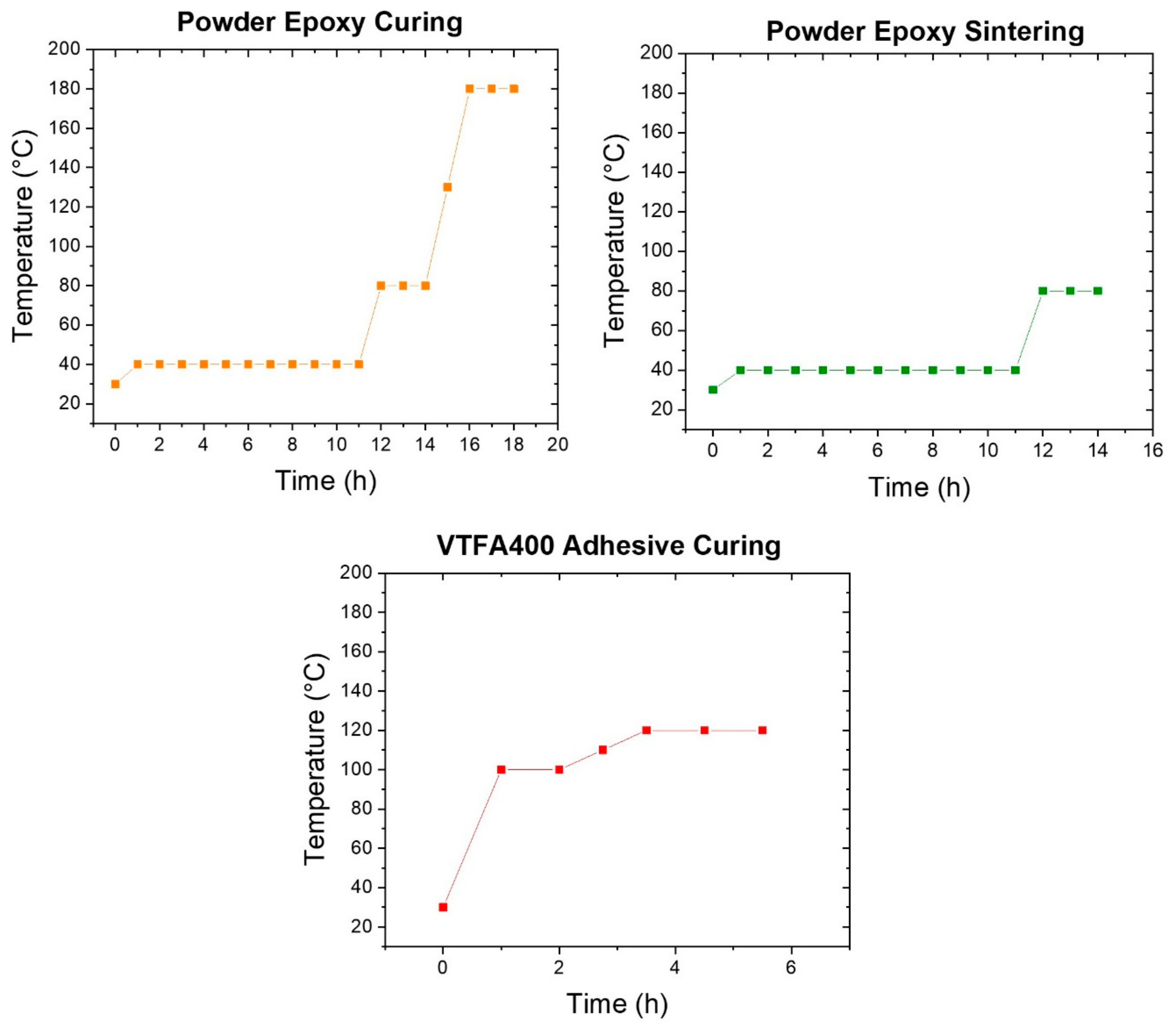
2.1.1. Powder Epoxy
2.1.2. Glass Fibers
2.1.3. Adhesive Prepreg
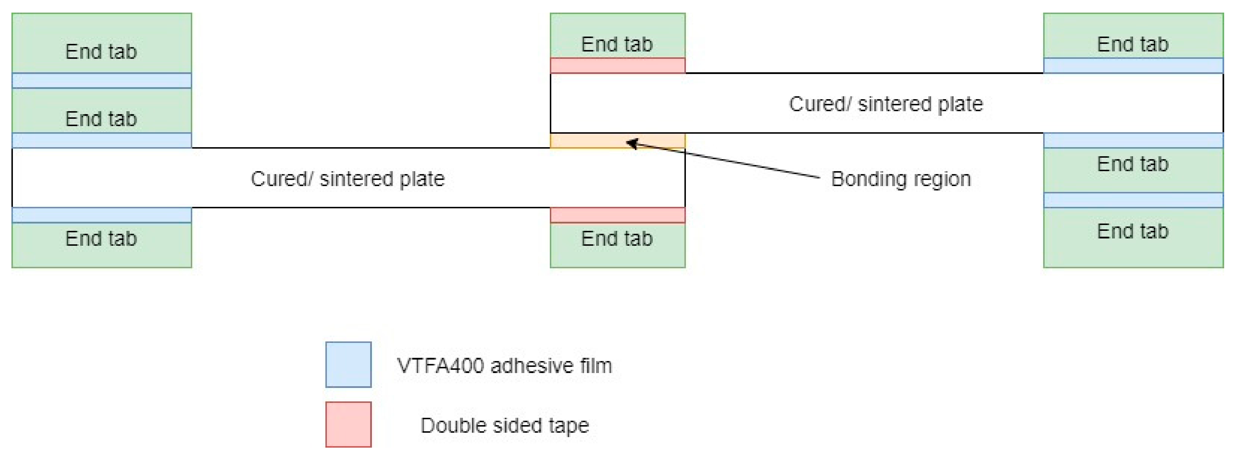
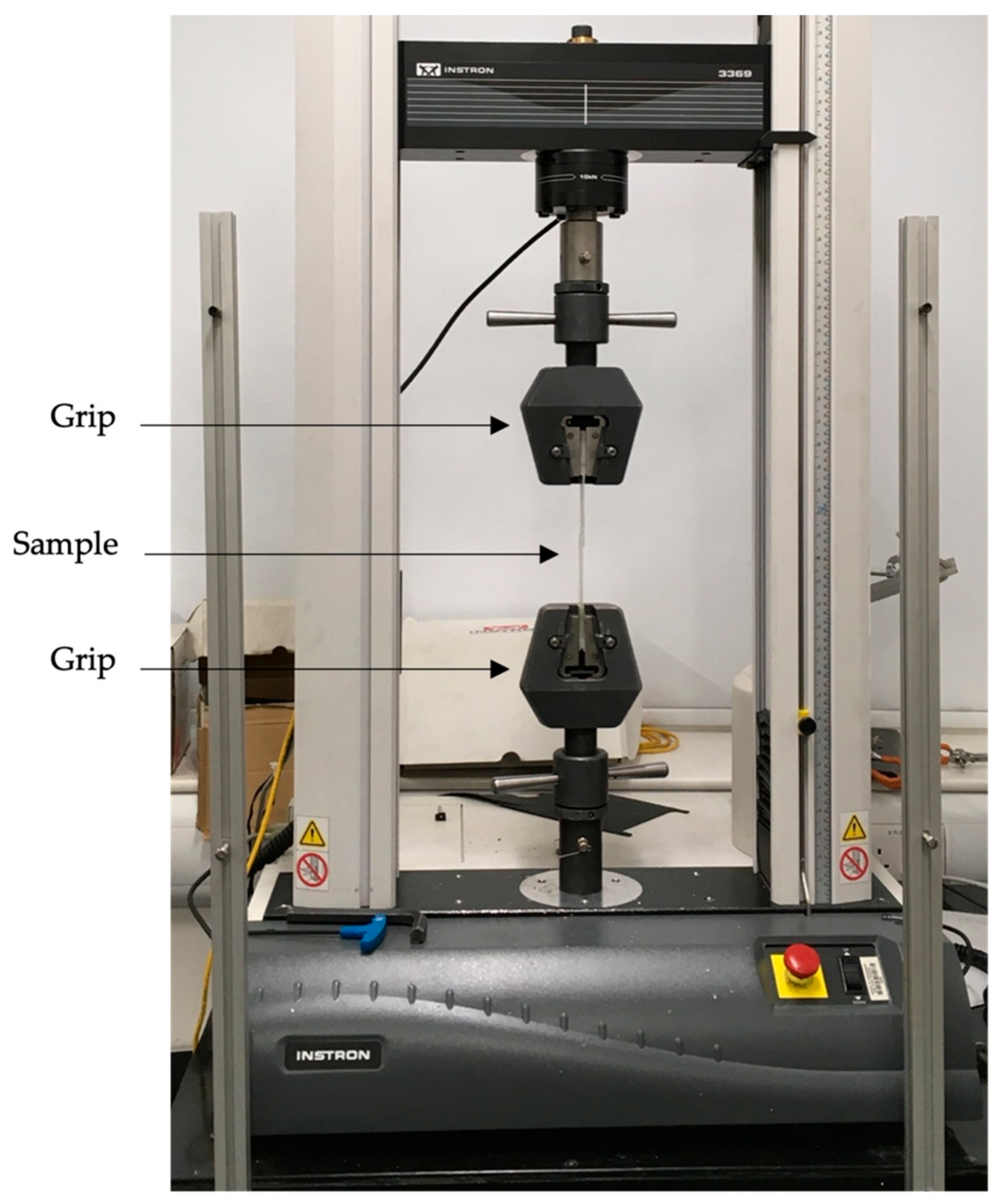
2.2. Lap Shear Samples Manufacturing and Testing
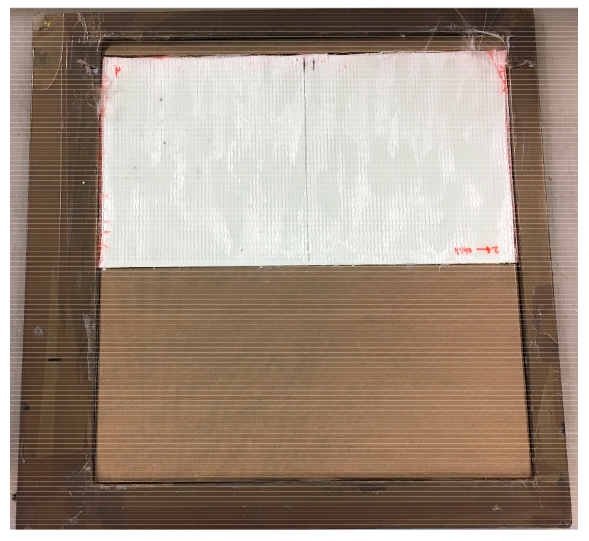
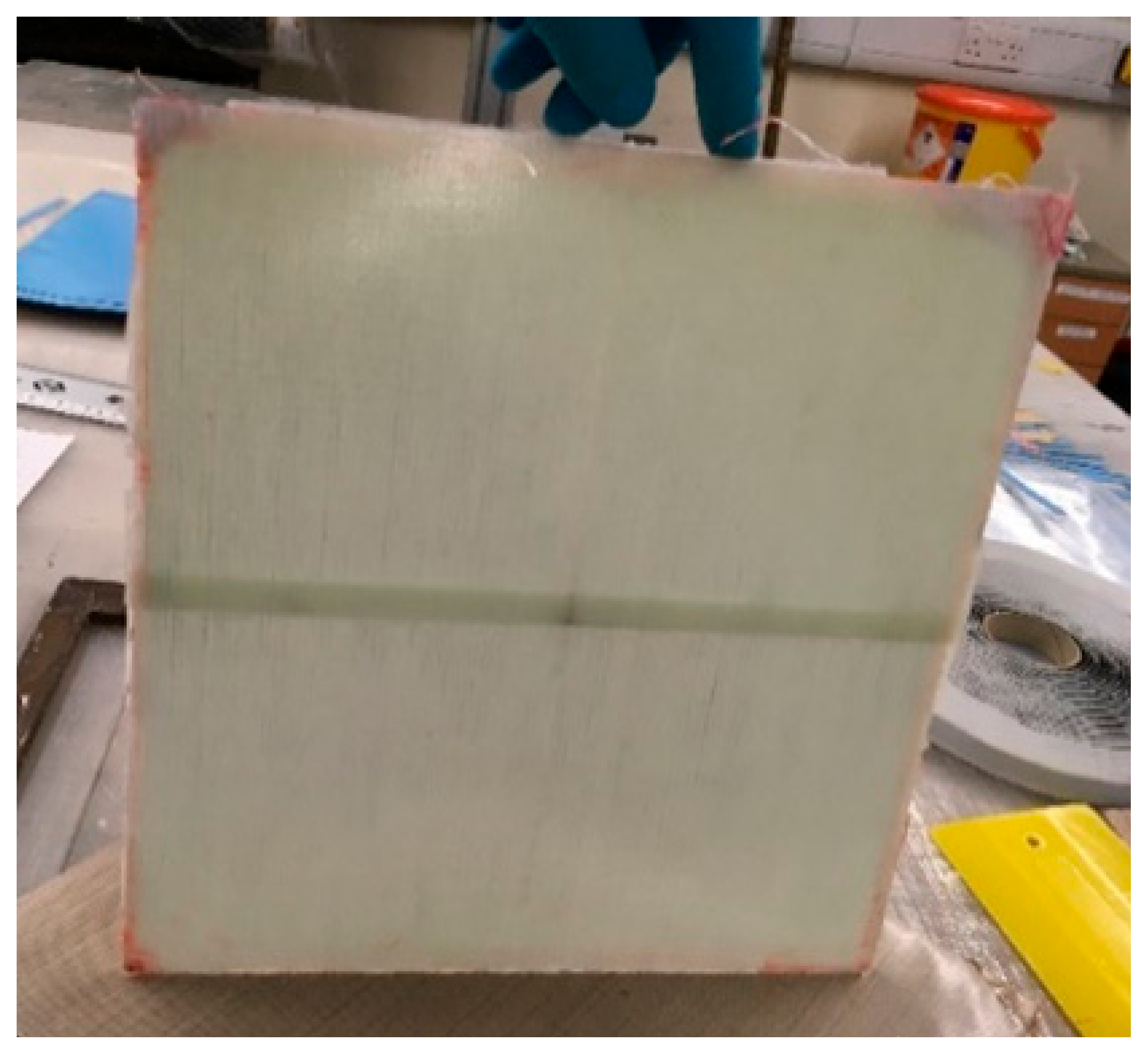
2.2.1. Manufacturing and Testing Overview
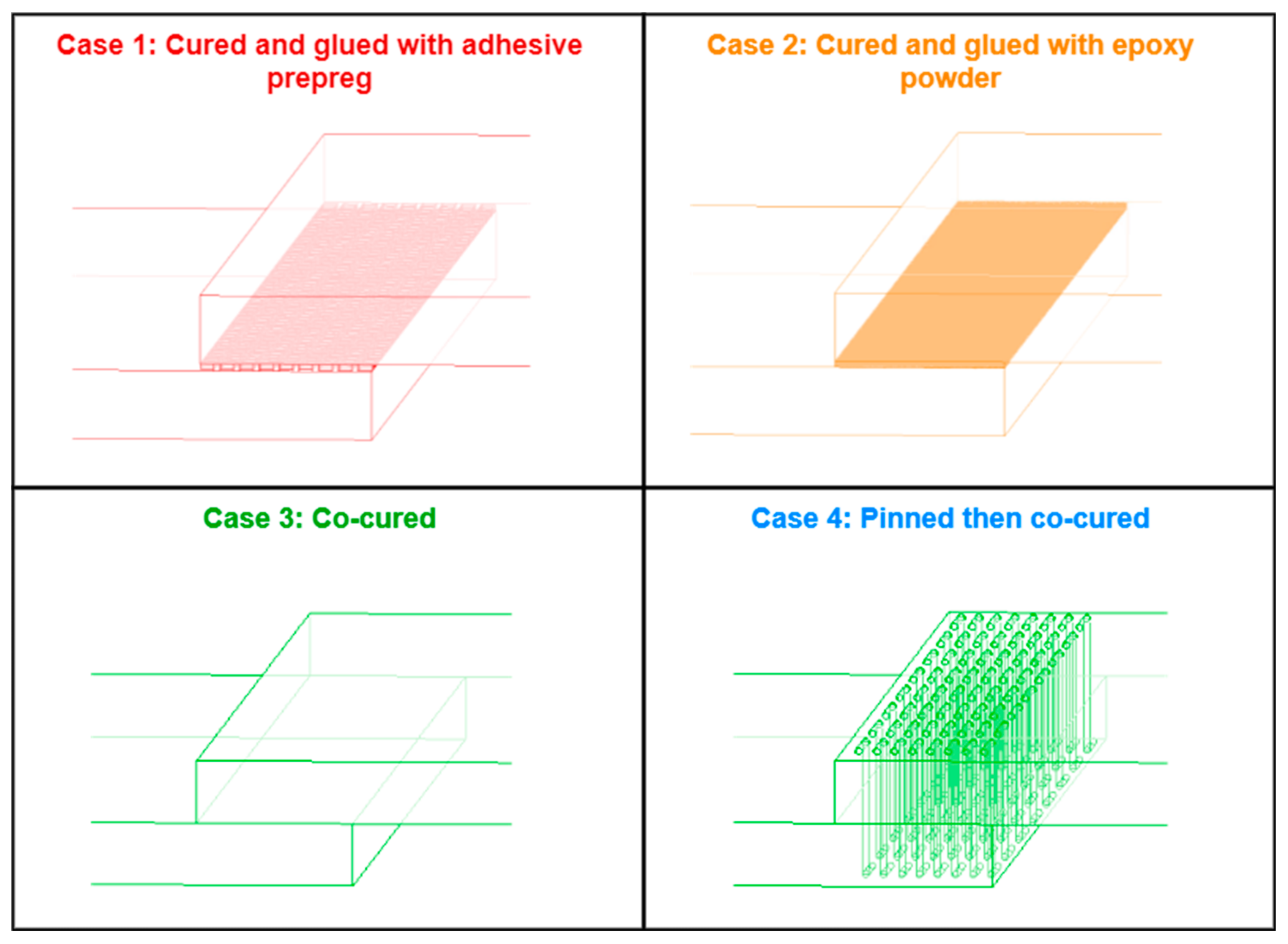
2.2.2. Sample Set Description
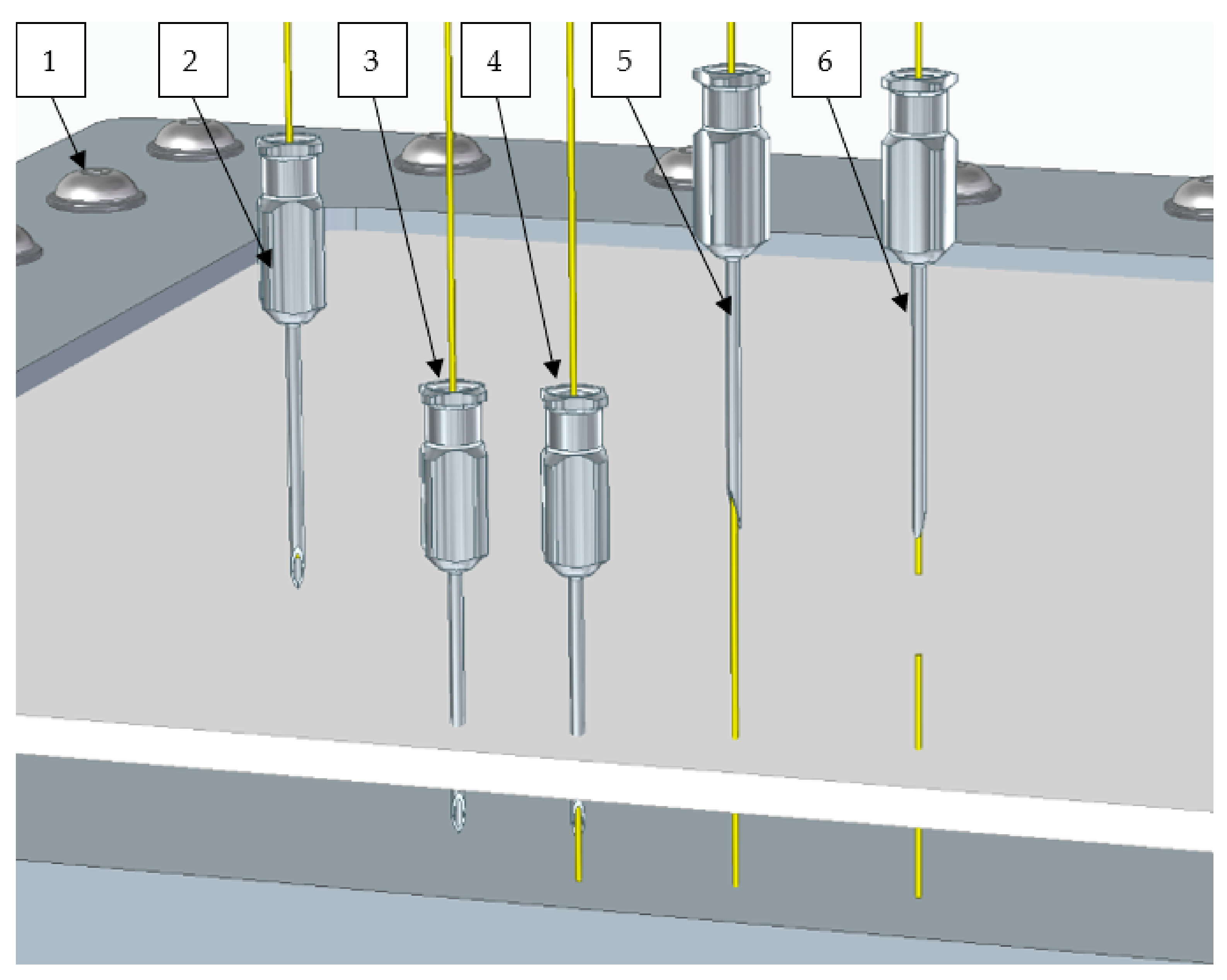
2.2.3. Pinning
- The fiber lay-up to be pinned was placed into a clamping frame which provides a fixed back-stop distance which can be adjusted by the addition of plates under the parts.
- The filament was threaded through an 18 Birmingham Gauge veterinary needle that was mounted in a 3D printed handle for operator convenience.
- The needle was pressed through the fiber in the desired locations.
- The filament was then gently threaded through the needle until it hits the backstop, this provides a consistent excess length on the underside of the part.
- The needle was then withdrawn whilst holding the filament in place. The closing of the fibers around the needle provides a light frictional force holding the filament in place.
- The filament was then cut above the part to match the backstop distance.
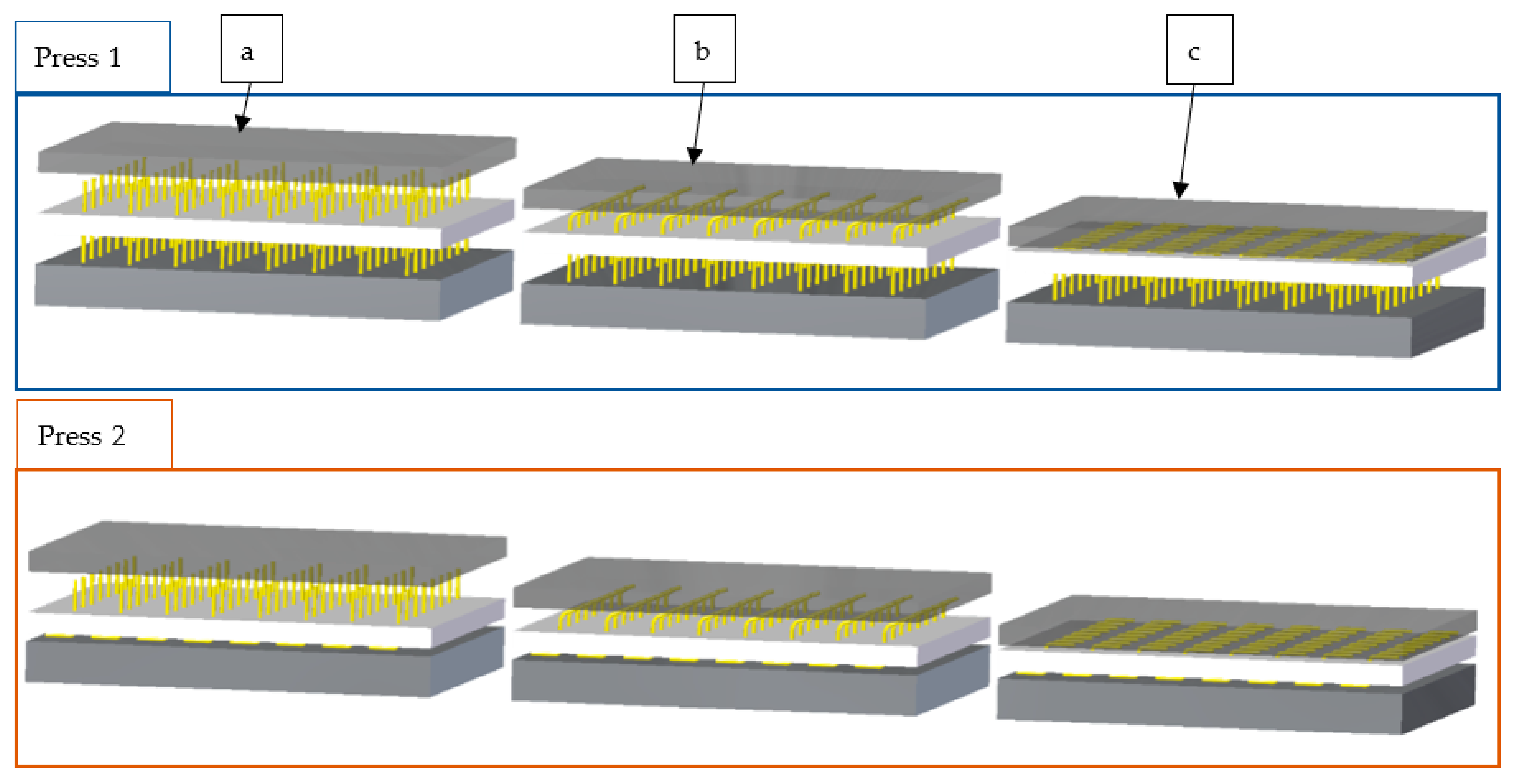
- In Press 1, a support plate is placed underneath the part (a). This prevents push-through of the pins.
- A press-plate is heated in an oven to 150 °C, placed on the upper surface of the part, and left to cool to ambient temperature overnight (b & c). The mass of this plate provides the necessary pressure to deform and flatten the pin ends. The flattening of the pins is illustrated as steps a, b & c in Figure 10.
- Once the first side has cooled, the fixture is inverted with the support plate now placed against the flattened pins.
- The process described for Press 1 is repeated for the underside of the part (Press 2: a–c).
2.2.4. Pinning Review
3. Results/Discussion—Mechanical Properties
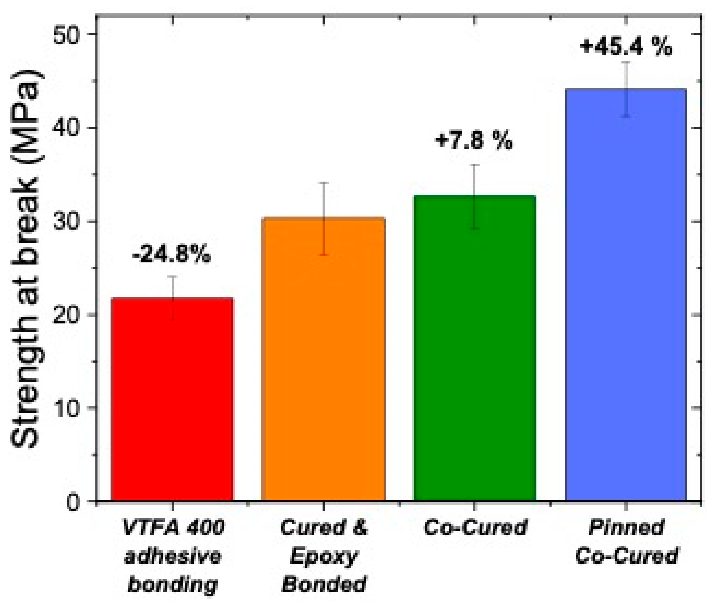
3.1. Lap Shear Tensile Testing
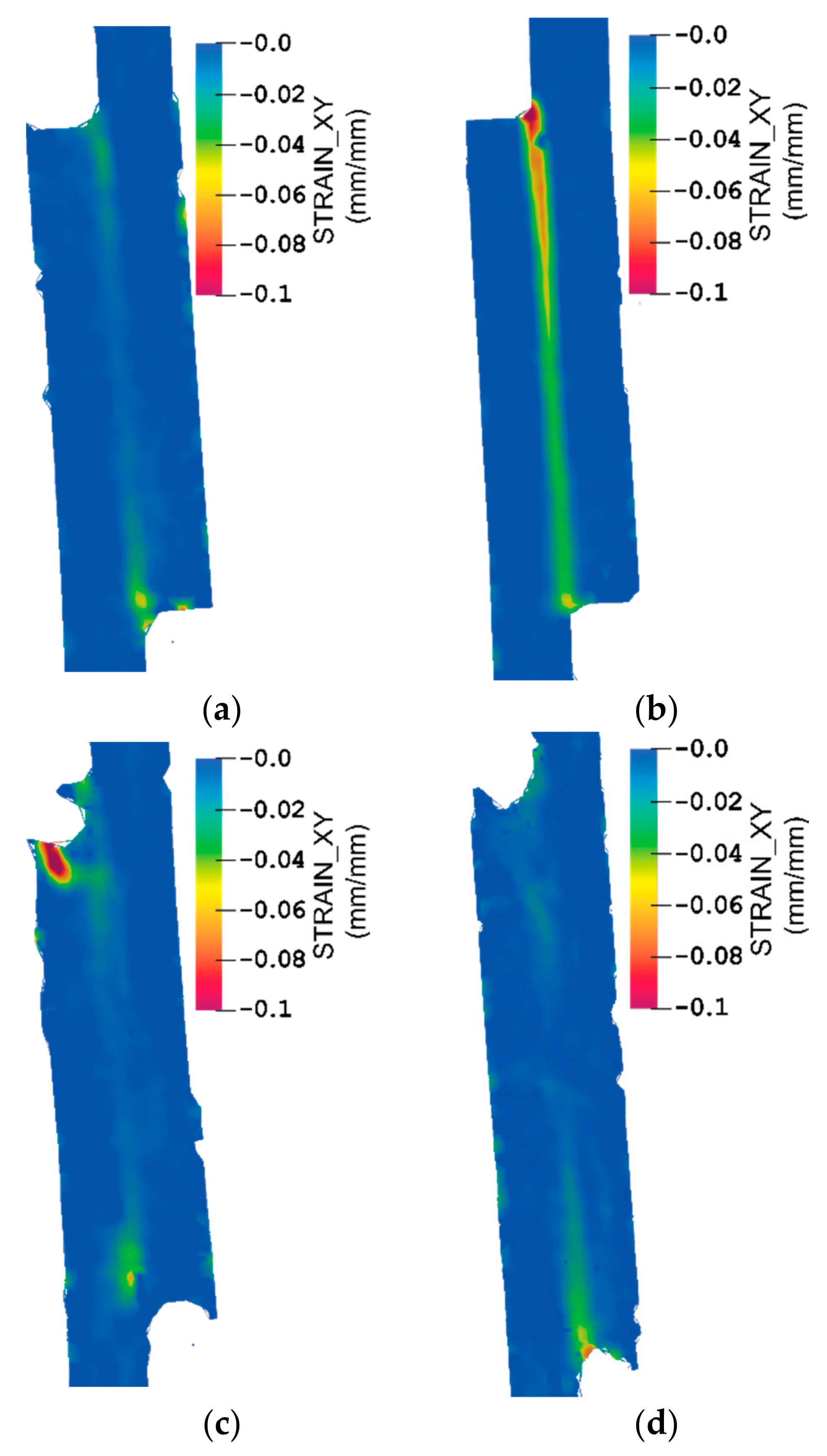
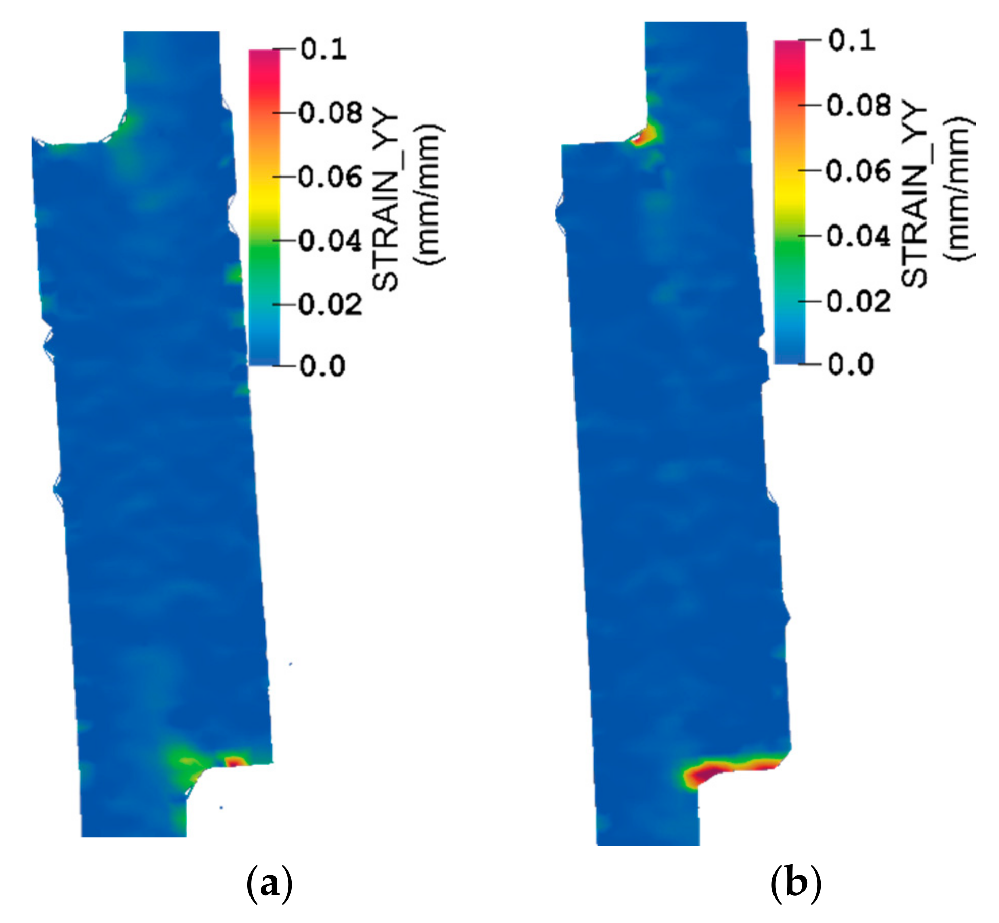
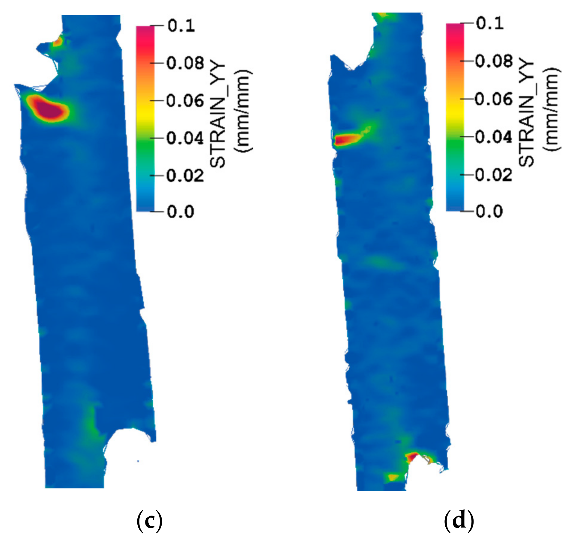
3.2. Digital Image Correlation (DIC)
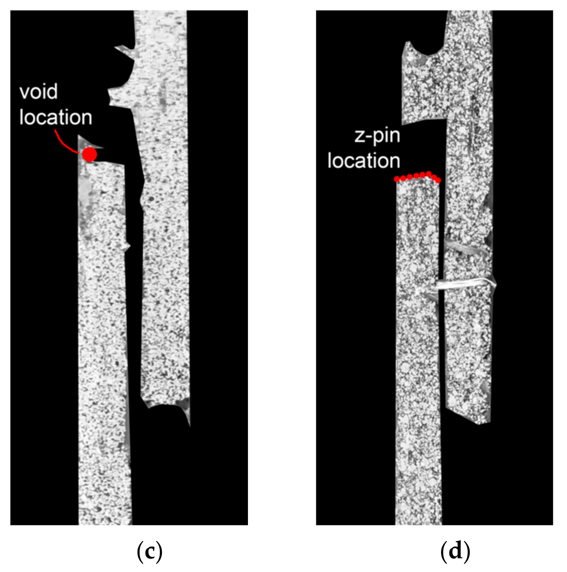
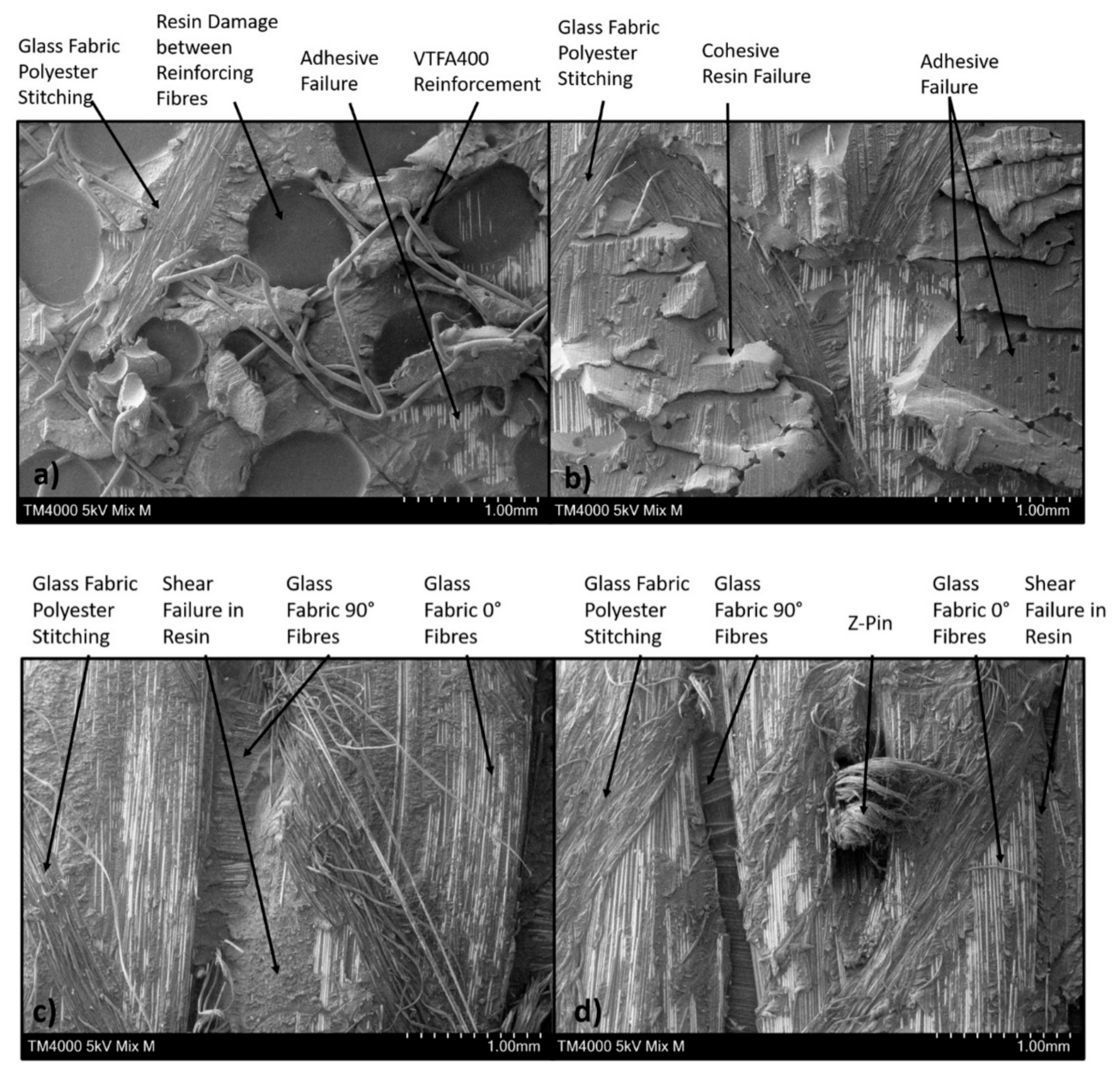
3.3. Fracture Behaviour
4. Conclusions
Author Contributions
Funding
Institutional Review Board Statement
Informed Consent Statement
Data Availability Statement
Acknowledgments
Conflicts of Interest
References
- Harshe, R. A review on advanced out-of-autoclave composites processing. J. Indian Inst. Sci. 2015, 95, 207–220. [Google Scholar]
- Centea, T.; Grunenfelder, L.K.; Nutt, S.R. A review of out-of-autoclave prepregs—Material properties, process phenomena, and manufacturing considerations. Compos. Part A 2015, 70, 132–134. [Google Scholar] [CrossRef]
- Armanios, E.; Bucinell, R.; Wilson, D.; Hart-Smith, L. Adhesive bonding of composite structures—Progress to date and some remaining challenges. J. Compos. Technol. Res. 2002, 24, 133. [Google Scholar] [CrossRef]
- Budhe, S.; Banea, M.D.; de Barros, S.; da Silva, L. An updated review of adhesively bonded joints in composite materials. Int. J. Adhes. Adhes. 2017, 72, 30–42. [Google Scholar] [CrossRef]
- SAE International on behalf of CMH-17. Design and analysis of bonded joints. In Composite Materials Handbook-17 (CMH-17); SAE International on behalf of CMH-17, A Division of Wichita State University: Warrendale, PA, USA, 2012; Volume 3, pp. 10-1–10-3. [Google Scholar]
- Dillingham, R.G. Composite bond inspection. In Structural Integrity and Durability of Advanced Composites; Beaumont, P.W.R., Soutis, C., Hodzic, A., Eds.; Woodhead Publishing: Cambridge, UK, 2015; pp. 695–706. [Google Scholar]
- Fuertes, T.A.S.; Kruse, T.; Körwien, T.; Geistbeck, M. Bonding of CFRP primary aerospace structures—Discussion of the certification boundary conditions and related technology fields addressing the needs for development. Compos. Interfaces 2015, 22, 795–808. [Google Scholar] [CrossRef]
- Hasan, Z.; Rader, J.; Olson, A.; Turpin, D.; Onge, R.S.; Amback, J. Design, analysis and fabrication of thick co-cured wing structures. Compos. Part B Eng. 2019, 177, 107335. [Google Scholar] [CrossRef]
- Huang, C. Study on co-cured composite panels with blade-shaped stiffeners. Compos. Part A Appl. Sci. Manuf. 2003, 34, 403–410. [Google Scholar] [CrossRef]
- Riley, B.L. AV-SB/GR Mk 5 airframe composite applications. Proceedings of the institution of mechanical engineers, part D: Transport engineering. SAGE J. 1986, 200, 167–183. [Google Scholar]
- National Aeronautics and Space Administration. Composite Chronicles: A study of the Lessons Learned in the Development, Production, and Service of Composite Structures; NASA Contractor Report 4620; NASA: Washington, DC, USA, 1994. [Google Scholar]
- Kageyama, M.; Yoshida, S. Development of XF-2 fighter composite structures (co-cured composite wings). In Proceedings of the 41st AIAA Structures, Structural Dynamics, and Materials Conference and Exhibit, Atlanta, GA, USA, 3–6 April 2000. [Google Scholar]
- Patterson, J.B. One-shot Manufacturing Techniques Developed for Carbon Fiber Prepreg Components. Ph.D. Thesis, Lehigh University, Bethlehem, PA, USA, 2018. [Google Scholar]
- Maguire, J.M.; Nayak, K.; Ó Brádaigh, C.M. Characterisation of epoxy powders for processing thick-section composite structures. Mater. Des. 2018, 139, 112–121. [Google Scholar] [CrossRef] [Green Version]
- Maguire, J.M.; Roy, A.S.; Doyle, D.; Logan, M.; Ó Brádaigh, C.M. Resin characterisation for numerical modelling of through-thickness resin flow during out of autoclave processing of thick-section wind or tidal turbine blades. In Proceedings of the 20th International Conference on Composite Materials, Copenhagen, Denmark, 19–24 July 2015; ICCM 20. Thomsen, O.T., Berggreen, C., Sørensen, B.F., Eds.; Aalborg University: Aalborg, Denmark, 2015. [Google Scholar]
- Robert, C.; Pecur, T.; Maguire, J.M.; Lafferty, A.D.; McCarthy, E.D.; Ó Brádaigh, C.M. A novel powder-epoxy towpregging line for wind and tidal turbine blades. Compos. Part B Eng. 2020, 203, 108443. [Google Scholar] [CrossRef]
- Robert, C.; Mamalis, D.; Alam, P.; Lafferty, A.D.; Cadhain, C.Ó.; Breathnach, G.; McCarthy, E.D.; Ó Brádaigh, C.M. Powder Epoxy Based UD-CFRP Manufacturing Routes for Turbine Blade Application; SAMPE: Southampton, UK, 2018. [Google Scholar]
- Glennon, C.; Flanagan, T.; Doyle, A.; Kelly, G.; Ó Brádaigh, C.M.; Finnegan, W. Development of Novel Manufacturing Techniques for Composite Tidal Turbine Blades; SAMPE: Southampton, UK, 2018. [Google Scholar]
- Floreani, C.; Robert, C.; Alam, P.; Davies, P.; Ó Brádaigh, C.M. Mixed-mode interlaminar fracture toughness of glass and carbon fibre powder epoxy composites—For design of wind and tidal turbine blades. Materials 2021, 14, 2103. [Google Scholar] [CrossRef] [PubMed]
- Bump, M.M.B. The Effect of Chemistry and Network Structure on Morphological and Mechanical Properties of Diepoxide Precursors and Poly(Hydroxyethers). Ph.D. Thesis, Faculty of the Virginia Polytechnic Institute, Virginia Polytechnic Institute and State University, Blacksburg, VA, USA, 2001. [Google Scholar]
- Floreani, C.; Cuthill, F.; Steynor, J.; Maguire, J.; McCarthy, E.D.; Niessink, M.J.; Di Noi, S.; Wittevrongel, L.; Flanagan, T.; Ó Brádaigh, C.M. Testing of a 6m hybrid glass/carbon fibre powder epoxy composite wind blade demonstrator. SAMPE J. 2021, 6, 6–14. [Google Scholar]
- SAERTEX®. U-E-591g/m2-1200mm Technical Datasheet; SAP No. 30001209; SAERTEX: Saerbeck, Germany, 2021. [Google Scholar]
- Reddy, S.S.P.; Suresh, R.; Hanamantraygouda, M.B.; Shivakumar, B. Use of composite materials and hybrid composites in wind turbine blades. Mater. Today Proc. 2021, 46, 2827–2830. [Google Scholar] [CrossRef]
- Structural Adhesives, Part II: Aerospace. Available online: https://www.compositesworld.com/articles/structural-adhesives-part-ii-aerospace (accessed on 17 June 2021).
- Archer, E.; McIlhagger, A.; Dixon, D.; Ralph, C.; Dooher, T.; Mosses, W. Controlled Micro Integration of Through Thickness Polymeric Yarns. 2019. Available online: https://cimcomp.ac.uk/wp-content/uploads/2019/08/Final-report-on-micro-extrusion_3.pdf (accessed on 23 June 2021).
- Turner, D.; Crozier, P.; Reu, P. Digital Image Correlation Engine v.3.0. Digit. Image Correl. Engine (DICE) Ref. Man. 2015. [Google Scholar] [CrossRef]
- Buck, N.V. Implementation of an Open-Source Digital Image Correlation Software for Structural Testing. Master’s Thesis, California Polytechnic State University, San Luis Obispo, CA, USA, 2020. [Google Scholar]
- Chang, P.; Mouritz, A.; Cox, B. Tensile Strength and Fatigue Properties of Z-Pinned Composite Lap Joints; Woodhead Publishing: Cambridge, UK, 2004; pp. 615–620. [Google Scholar] [CrossRef]
- Bonhomme, J.; Argüelles, A.; Viña, J.; Viña, I. Fractography and failure mechanisms in static mode I and mode II delamina-tion testing of unidirectional carbon reinforced composites. Polym. Test. 2009, 28, 612–617. [Google Scholar] [CrossRef]
- Stukhlyak, P.D.; Buketov, A.V.; Panin, S.V.; Maruschak, P.O.; Moroz, K.M.; Poltaranin, M.A.; Vukherer, T.; Kornienko, L.A.; Lyukshin, B.A. Structural fracture scales in shock-loaded epoxy composites. Phys. Mesomech. 2015, 18, 58–74. [Google Scholar] [CrossRef]
- Hassan, E.; Zekos, I.; Jansson, P.; Pecur, T.; Floreani, C.; Robert, C.; Ó Brádaigh, C.M.; Stack, M. Erosion mapping of through-thickness toughened powder epoxy gradient Glass-Fiber-Reinforced Polymer (GFRP) plates for tidal turbine blades. Lubricants 2021, 9, 22. [Google Scholar] [CrossRef]


Publisher’s Note: MDPI stays neutral with regard to jurisdictional claims in published maps and institutional affiliations. |
© 2021 by the authors. Licensee MDPI, Basel, Switzerland. This article is an open access article distributed under the terms and conditions of the Creative Commons Attribution (CC BY) license (https://creativecommons.org/licenses/by/4.0/).
Share and Cite
Noble, T.; Davidson, J.R.; Floreani, C.; Bajpai, A.; Moses, W.; Dooher, T.; McIlhagger, A.; Archer, E.; Ó Brádaigh, C.M.; Robert, C. Powder Epoxy for One-Shot Cure, Out-of-Autoclave Applications: Lap Shear Strength and Z-Pinning Study. J. Compos. Sci. 2021, 5, 225. https://doi.org/10.3390/jcs5090225
Noble T, Davidson JR, Floreani C, Bajpai A, Moses W, Dooher T, McIlhagger A, Archer E, Ó Brádaigh CM, Robert C. Powder Epoxy for One-Shot Cure, Out-of-Autoclave Applications: Lap Shear Strength and Z-Pinning Study. Journal of Composites Science. 2021; 5(9):225. https://doi.org/10.3390/jcs5090225
Chicago/Turabian StyleNoble, Thomas, James R. Davidson, Christophe Floreani, Ankur Bajpai, William Moses, Thomas Dooher, Alistair McIlhagger, Edward Archer, Conchúr M. Ó Brádaigh, and Colin Robert. 2021. "Powder Epoxy for One-Shot Cure, Out-of-Autoclave Applications: Lap Shear Strength and Z-Pinning Study" Journal of Composites Science 5, no. 9: 225. https://doi.org/10.3390/jcs5090225
APA StyleNoble, T., Davidson, J. R., Floreani, C., Bajpai, A., Moses, W., Dooher, T., McIlhagger, A., Archer, E., Ó Brádaigh, C. M., & Robert, C. (2021). Powder Epoxy for One-Shot Cure, Out-of-Autoclave Applications: Lap Shear Strength and Z-Pinning Study. Journal of Composites Science, 5(9), 225. https://doi.org/10.3390/jcs5090225