1. Introduction
The transition into the digital, connected world necessitates the need for efficient and increased transportation of cargo around the world. Global freight demands are expected to triple by 2050, with an annual increase of 3.1% until 2030 [
1]. Increasing global demands on the rail freight industry dictate that performance, reliability and safety are key priorities. Therefore, innovation is required to optimise rolling stock design. The UK’s Rail Technical Strategy [
2] outlines the desire for lighter and more efficient rail vehicles in the pursuit of increased capacity and performance.
The aerospace, marine and automotive industries have prioritised lightweighting as a means of increasing efficiency and reducing environmental impact [
3]. Polymer composites have been used extensively for this purpose, due to their exceptional strength-to-weight ratio and durability. However, the uptake of composite materials in the rail industry has been slow. This is especially prominent in the freight division. Steel is still the predominant material used for rail freight vehicles due to its good strength, formability and weldability at a low cost per kilogram. Only in recent years have polymer composites been considered a viable option for use on mainline rolling stock.
The main barrier to the implementation of composite materials for rail freight vehicles is the high first cost compared to metals. This in addition to other factors such as stringent fire, smoke and toxicity (FST) regulations, as well as inferior impact resistance, has hindered their use. These are key challenges that need to be addressed holistically to increase the adoption of composites in the rail freight industry.
The structural integrity, and therefore resistance to damage, is imperative for the continued safe operation of rail freight vehicles. During their design and construction, impact resistance must be considered in order to mitigate potential issues arising from projectile impact. This involves the damage prediction of vehicle structures to ensure they can withstand impacts during daily operation.
It is difficult to accurately predict the impact performance of a composite laminate due to its anisotropic configuration. From this stems the numerous factors that influence the damage tolerance of a composite structure [
4]. Such factors include the composite layup properties, component geometry and external loading applied to the structure. The highly stressed condition of rail vehicle body panels has the potential to influence the impact performance of the final composite structure. This is especially prudent for pressurised composite structures that are subjected to a high degree of in-plane loading.
This study investigates the impact resistance of the composite vessel as part of a rail freight tank wagon. The consequential nature of preloading on the impact performance of the final vessel structure is the primary focus of this research. Tank wagon vessels are of particular interest due to the intricate loading conditions they are subjected to during normal operation. Previous literature regarding preloaded composite structures under impact loading mainly considers quasi-isotropic composite layups with simple load cases. They are therefore not applicable to the complex characteristics of a tank wagon vessel.
A novel aspect of this work is the understanding of how the preload direction in relation to the principal fibre directions can influence the laminate impact performance. This is contrary to previous studies that only consider the magnitude of preloading. Understanding the effect of structural preload will inform future studies of composite freight tank wagon design.
The implications of this study will be applicable to other large pressurised composite structures. This includes the implementation of high-pressure hydrogen storage technologies for rail and primary aerostructures such as pressurised fuselages [
5,
6]. This is especially true if these structures exhibit a nonstandard layup.
2. Composite Freight Tank Wagons
Rail freight haulage is a key mode of freight transport in the UK, with 75.4 million tonnes of freight transported in 2018, equating to 5% of total freight moved (including road, rail and shipping) [
7]. Of this, 6% of the freight transported by commodity was oil and petroleum. This was transported in freight tank wagons. In addition to oil and petroleum, they are used to carry numerous other fluids such as liquid fertilisers, chemicals, food-grade oils, ethanol and liquified gas. These fluids can be carried in a pressurised or unpressurised state in the wagon.
Freight tank wagons are closed-top, cylindrical bodied freight wagons consisting of the wheelsets, underframe and vessel (see
Figure 1). The vessel is the primary structural member of the wagon. Because of this, the vessel is highly stressed, making its structural integrity of paramount importance. Freight tank wagons, unlike the majority of other freight wagons, do not use the underframe for load transfer through the structure. The purpose of the underframe is to support equipment and transfer loads to and from the vessel.
A composite freight tank wagon has the potential for increased operational efficiency and reduced energy consumption [
8]. This is similar to the benefits for passenger train weight reduction. However, the additional benefit provided by a lightweight composite design for a freight wagon is the opportunity for an increased payload [
9]. The two key benefits for a freight vehicle with increased payload are as follows:
Increased profits due to larger deliveries, less constrained by freight train length and weight;
A reduction in the total number of train movements required as more cargo is transported at a time, reducing operational costs, life cycle costs and energy consumption.
The literature suggests that the viability of using fibre reinforced composite materials for the vessel of a freight tank wagon has not been studied. This could be for several reasons, centred around the cost sensitivity of the rail freight industry. The long lifespan of a typical rail freight vehicle means that high manufacturing costs can often be offset by lower operational costs, therefore providing a case for the implementation of composite materials.
There are three types of composite pressure vessels: metal-lined composite tanks (Type III), polymer-lined composite tanks (Type IV) and all-composite tanks (Type V). Type IV vessels are highly desirable for composite applications due to the added fibre protection provided by the liner, which does not significantly increase the mass of the vessel [
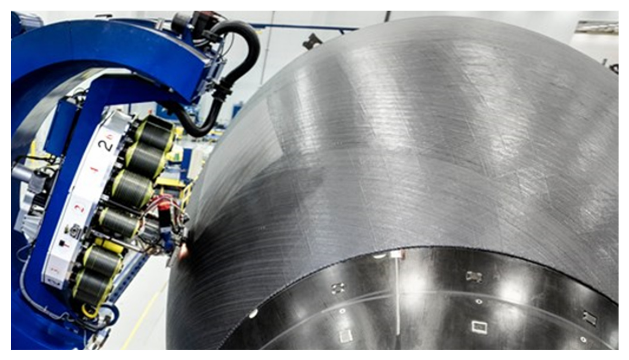
5]. The primary polymer composite manufacturing process to produce hollow, circular components such as pressure vessels is filament winding. In this process, fibre tows are wound under tension, at prescribed angles, onto a convex rotating mandrel. For Type III and Type IV vessels, the mandrel can simultaneously be used as the liner. This manufacturing process is widely used to produce large structures, most notably for the Boeing 787 “Dreamliner” fuselage (see
Figure 2).
The mechanical performance of the composite vessel is dependent on the material properties and the filament winding parameters [
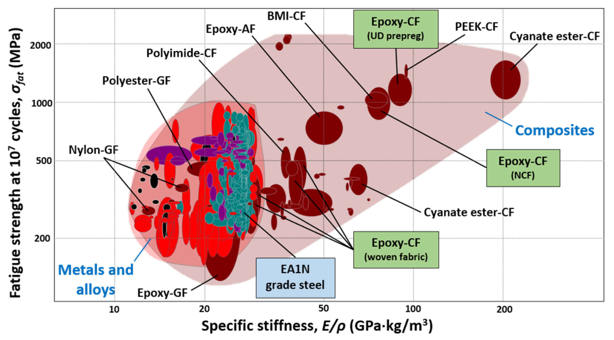
10]. High specific stiffness and fatigue strength are properties required for all rolling stock, to warrant high levels of durability.
Figure 3 illustrates a Cambridge Engineering Selection (CES) material selection chart for specific stiffness and fatigue strength. This figure illustrates that carbon fibre reinforced polymer (CFRP) composites exhibit superior properties over metallics and other reinforced polymer composite materials. Epoxy resins are generally superior to other thermosets due to elevated mechanical properties, high levels of fibre–matrix adhesion and resistance to environmental degradation [
11].
CFRP is superior to steel in terms of its inherent strength-to-weight ratio, fatigue resistance and corrosion resistance. However, one of the most serious limitations of CFRP laminates is their response to localised impact loading. The ductility of steel means that high levels of impact energy can be absorbed in the structure (via plastic deformation before failure). Composites, on the other hand, are brittle. This reduces the quantity of energy absorbed before laminate failure. Because of this, it is of paramount importance that the impact resistance of retrofitted composite vessels is assessed in comparison with the original steel architecture. The necessity of this stems from the highly stressed nature of a freight tank wagon vessel, of which structural failure must be avoided.
3. Impact Performance of Composites
The impact study of composite structures can be broken down into two categories: high-velocity, ≅50 m/s (small mass), and low-velocity, ≅10 m/s (large mass), impacts [
12]. The categories of impact loading are important as the energy transfer, energy dissipation and damage propagation are all dependent on impact velocity [
13]. Low-velocity impacts are the most common impacts to occur on tank wagons during manufacture, general operation and maintenance. These impacts are a cause for concern as they are not always easy to detect via visual examination.
The severity of low-velocity impact damage on CFRP laminates depends on many parameters including projectile/impactor properties, impact energy, geometry, layup properties and preloading. This results in the impact behaviour being difficult to predict. Moreover, the complex damage modes that occur such as matrix cracking, delamination and fibre fracture add to the complexity of damage prediction within composites [
14]. To address this, a large array of literature is available in the form of analytical modelling [
15,
16,
17,
18,
19], numerical simulation using a range of constitutive models [
20,
21,
22,
23,
24] and experimental impact tests [
25,
26,
27,
28,
29].
Preloading is a key parameter that can affect composite impact performance. The extent of preloading can be highly variable, depending on the operating conditions of the structure. It is therefore important that the effect of preload on impact resistance is well understood.
Research into the analysis of the effect of preloading on CFRP laminates has been published. Chiu et al. [
30] and Sun and Chen [
31] have assessed the effects of both tensile and compressive preloading on the impact resistance of composite laminates. The authors determined that tensile preloading increased the peak impact force and subsequently the damage area for a given impact energy. This is due to the preloaded specimens having a higher flexural stiffness. Recent studies have illustrated that tensile preload results in increased laminate energy absorption and therefore impact damage [
32,
33,
34,
35,
36,
37]. Whittingham et al. [
38] illustrated that the overall effect of preloading on the peak load, absorbed energy and penetration depth is exacerbated with higher levels of impact energy. These studies indicate that preloading has the potential to influence the impact performance of a composite laminate.
With regards to a freight tank wagon vessel, a range of numerical and experimental studies have been conducted to analyse the low-velocity impact resistance of a CFRP filament-wound pressure vessel. These include analysis of the impact response [
39,
40,
41,
42], damage prediction [
43,
44] and residual burst strength after impact [
45,
46,
47,
48]. Moreover, the effect of pressure-induced hoop and axial preload has also been studied [
49,
50]. This research mainly focuses on small composite vessels as opposed to large composite structures.
More generally, advancements in impact performance have been achieved using hybridisation techniques where commercial fibres such as Kevlar, Zylon and Dyneema are combined with standard reinforcing fibres [
51,
52]. Further studies have been conducted on fibre metal laminates (FMLs), GLARE and ARALL, which use a ductile outer surfacing material to protect the fibre reinforcement. The ductility in the metallic helps mitigate impact damage [
53].
The literature is limited concerning the experimental impact performance of large composite pressure vessels, specifically how the preloading can influence the damage tolerance. This is due to the costly nature of producing large filament-wound structures and testing their impact response. Fortunately, although the damage response of shells is more severe than that of plates [
54], the effect is negligible when the curvature becomes small. Krishnamurthy et al. [
55] illustrated numerically that the maximum contact force under impact increases only marginally when the curvature is small. Zhao and Cho [
56] concluded that damage size does increase for small shell curvatures compared to flat plates; however, a radius (
)/thickness (
) value of 41 was seen to only increase the damage size by
2%. The vessel of a freight tank wagon, with an
value of 215, therefore exhibits a curvature that does not influence the laminate damage response. Hence, it is more appropriate to consider flat laminates than heavily curved shells for large composite pressure vessels.
Laminate dimensions, as opposed to curvature, need to be accounted for in this experimental program. Decrements in both lateral displacement and contact time are common with increasing laminate thickness, along with penetration depth and damage area [
57,
58,
59]. However, appropriate dimensional scaling can be implemented when analysing impact damage, meaning it is not necessary to produce large, expensive composite laminates for impact testing [
60]. These scaling rules are generally only valid for highly elastic impacts.
Although the addition of a liner material can increase the impact performance of a composite vessel, as is the case for Type III and Type IV composite tanks, the liner is neglected in this study as it is not a load-bearing component. It, therefore, does not influence the effect of structural preloading, which is the primary focus of this study.
4. Methodology
To determine the impact properties of the freight tank wagon composite vessel, flat preloaded composite plates were to be impacted using a conventional low-velocity drop tower. The preloading incident on the flat laminates would provide a worst-case scenario in operation: simulating the effect of vehicle loading () and internal pressure () that acts on the composite vessel in the axial and hoop directions. The specimen preloading was applied using a custom biaxial rig. Uniaxial loading simulated the vehicle-loading-induced stress and the axial constituent of the pressure stress . The biaxial loading also simulated the hoop constituent of the pressure stress . This loading pattern enables the understanding of the influence of preload direction on the laminate impact performance. The effects of the nonstructural underframe are neglected, meaning all loading is transferred through the vessel body.
Figure 4 illustrates the region where a composite specimen was extracted from the body of a freight tank wagon vessel and the forces acting on this specimen. This specimen was extracted from the centreline of the vessel, on the underside. This location was chosen due to the high occurrence of impact loading expected here coupled with the low levels of bending-induced in-plane shear stresses that cannot be applied with the biaxial rig. The through-thickness shear stresses were assumed to be negligible in this study.
4.1. Preparation of Test Specimens
The CFRP test specimens were produced from XC130 300 g Unidirectional Prepreg Carbon Fibre [
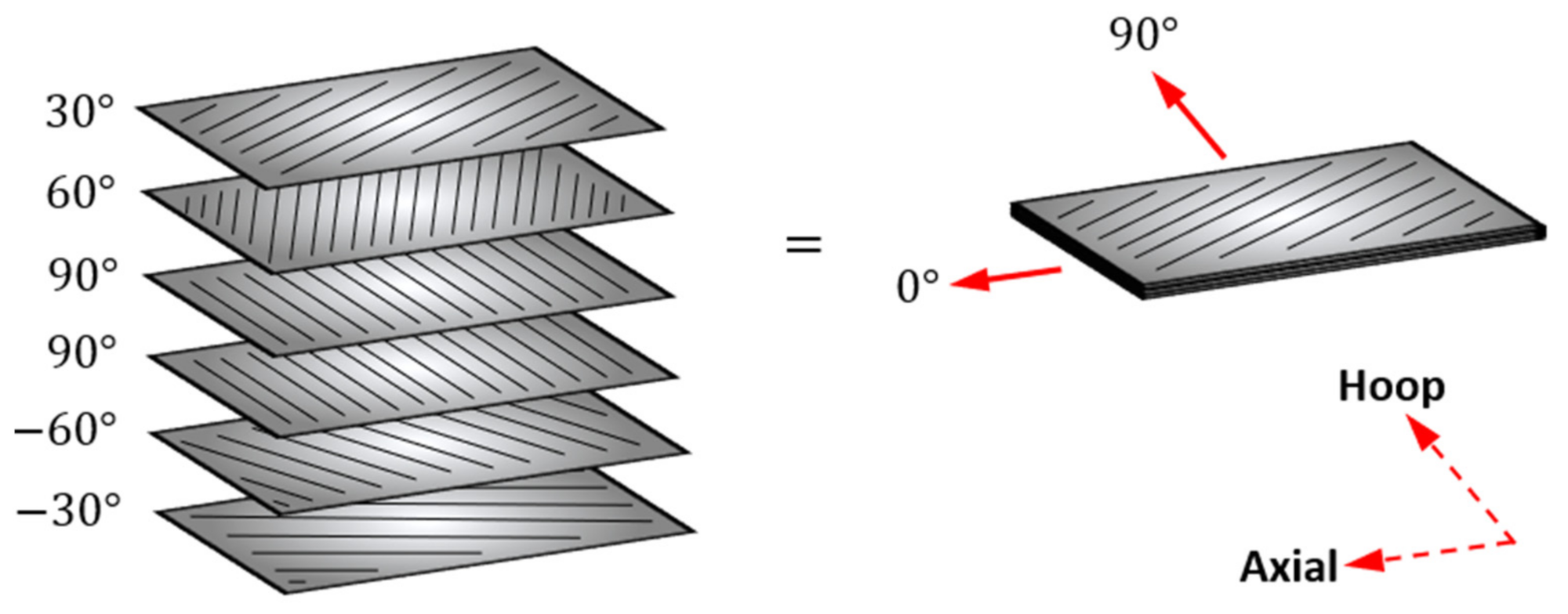
61]. A total of 25 specimens were prepared by hand layup with
plies. This represents a feasible layup for a CFRP pressure vessel under the prescribed loading. Plies in the 90° direction ensure good strength in the pressure-induced hoop stress direction. The inclusion of
60° plies is due to this being the approximate optimal angle for the maximum burst performance of a composite vessel [
62]. Axial strength is achieved with
30° plies. It is difficult to achieve small fibre angles when filament winding large structures due to supports required at each end. In addition, the double curvature geometry of the end-caps required for a pressure vessel adds additional complexity.
Figure 5 illustrates the layup orientations used for the composite specimens.
The specimens produced were 150 mm × 100 mm in size in order to fit the impactor rig. They had a consolidated thickness of 1.85 ± 0.06 mm. Although this is thinner than the 6.5 mm wall thickness of a steel wagon, the true thickness of a CFRP vessel is unknown and would require optimisation during the design/validation process. Dimensional scaling rules outlined by Qian and Swanson [
60] can be applied for elastic impacts. The specimens were autoclave cured at 120 °C (1 h) and post-cured at 130 °C (2 h), as recommended by XPREG.
4.2. Preloading
The preload conditions incident on the specimens were determined by analysing the maximum operating conditions that would be exerted on a composite tank wagon vessel during service. British Standard BS EN 12633–2 [
63] details the structural requirements for railway vehicle bodies. From this standard, a maximum tensile force of 1500 kN is used as the axial load case,
. This was used as a critical loading case since the literature suggests that tensile forces are the most detrimental to the impact performance of a composite laminate [
30].
The tensile stress can thus be determined.
where
is the axial stress induced by the vehicle loading,
. Moreover,
is the vessel external radius and
is the wall thickness. The pressure stress for the vessel can be deduced from standard thin-wall vessel stressing equations [
64].
where
is the hoop stress,
is the axial stress induced by pressure loading,
is the radial stress and
is the internal pressure. The radial stress can be assumed negligible for a large, thin-walled pressure vessel. Finally, the force applied to each individual specimen as a result of these stresses can be calculated.
where
is the specimen axial force,
is the specimen hoop force,
is the specimen long side cross-sectional area (CSA) and
is the specimen short side CSA.
Table 1 defines the parameters that were used for the force calculation. The final preload values are defined in
Table 2, with their values calculated using Equations (1)–(6). The preload cases are split into unloaded, uniaxial (axial) and biaxial (axial and hoop) in order to understand how the different loading scenarios influence the damage resistance of a large filament-wound composite structure. The calculated forces result in identical stresses induced in the 1.8 mm composite laminates as compared to the stresses in the original 6.5 mm thick vessel structure.
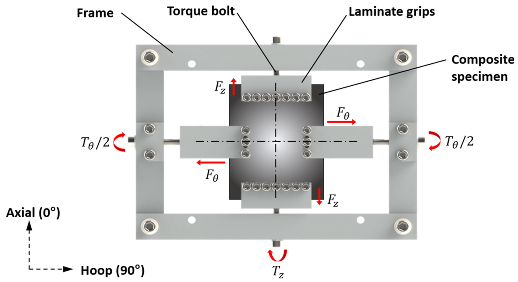
In order to apply these loads to the specimen, a biaxial rig was manufactured that can be mounted to the bed of the drop tower (see
Figure 6). The rig consists of four individual clamps that secure the specimen in place. The force is transferred to the specimen through the torque which is applied to the bolts located on the edge of the rig. The torque required to produce the desired forces was calculated as follows:
where
is the bolt tightening torque,
is the bolt friction coefficient,
is the bolt major diameter and
is the bolt force. The bolt friction value,
, was calculated to be 0.45. The torque values are illustrated in
Table 2.
To validate the use of the rig for simulating laminate stresses, finite element analysis (FEA) was conducted using ANSYS [
65]. Both the magnitude and distribution of stresses within the composite specimens were analysed. The mesh-independent response was analysed in a mesh convergence study which determined that a 3 mm mesh is sufficient for the purposes of this exercise. The FEA model, therefore, consisted of 1951 elements; 1683 SHELL181 elements for the plate and 268 SURF154 elements for the boundary condition contact interfaces, as selected by the solver.
A fixed-displacement boundary condition was used at the rear of the plate. This was because the rear bolt on the rig was not easily accessible since it was located inside the tower chamber. Forces were applied perpendicular to the clamped edges as specified in
Table 2.
Figure 7 illustrates the stresses in both the axial and the hoop directions, with the clamped edges removed from the plots to aid clarity. In both cases, the central nodes were taken as the impact centre, and the stresses were inspected at these points. A pinball radius of 30 mm was used around the impact centre to characterise the distribution of stresses in the laminate.
The axial stress distribution was numerically derived to be ±3% within the pinball radius and ±8% for the hoop stress distribution. These values were deemed to be acceptable, indicating a low level of stress distribution around the impact centre when preloaded. The FEA was validated by comparing the axial and hoop stress at the impact centre with the values tabulated in
Table 2. The axial stress at the impact centre was found to be approximately 7% lower than the analytically derived value, and hoop stress was found to be approximately 5% greater than the analytically derived value.
4.3. Impact Testing
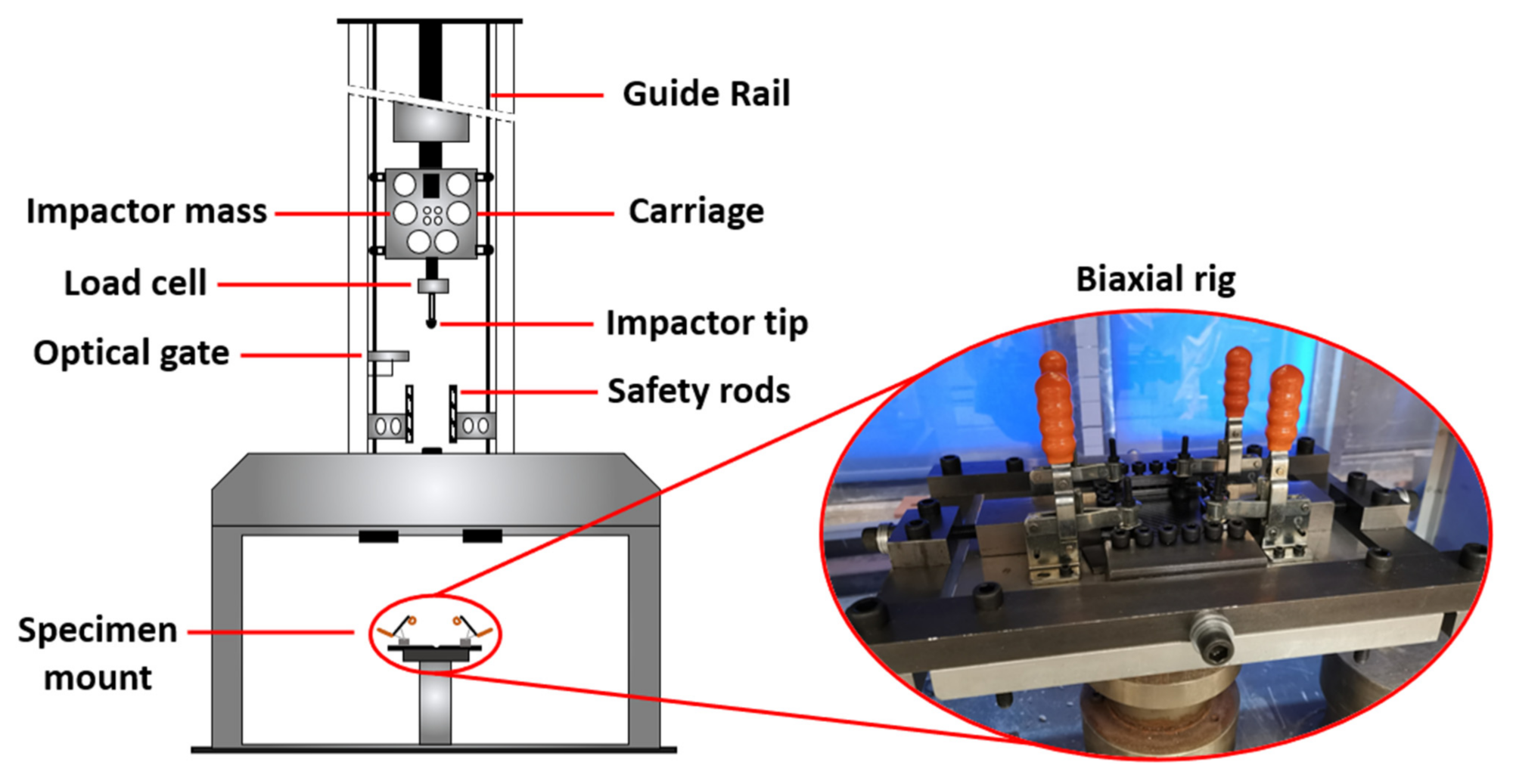
Dynamic impact tests were performed using a Rosand type 5 instrumented drop-weight impact tester (shown in
Figure 8) equipped with a 50 kN load cell. The drop tower (3 m height) was equipped with an impactor of mass 8.8 kg with spherical diameter of 12 mm for the drop tests. A range of drop heights (0.1, 0.15, 0.175 and 0.2 m) were chosen in order to evaluate the impact resistance of a composite laminate over the entire damage range: from BVID (barely visible impact damage) to complete laminate penetration. All testing was undertaken in accordance with the relevant standard, ASTM D7136–12 [
66].
From the initial potential energy, the impact energy (
) for each respective drop height can be calculated (accounting for friction in the hammer guide).
where
is the impactor mass,
is acceleration due to gravity and
is the drop height. From the chosen drop heights, the resulting impact energies were as follows: 7.85, 11.78, 13.75 and 15.71 J.
The peak force and force time history were measured using an integrated load cell within the drop tower. An optical gate measured the incident velocity of the impact head immediately before and after impact. To prevent multiple strikes of the impactor, a solenoid-controlled pneumatic ram brake located on the base of the drop tower was armed, catching the hammer after the initial strike.
Two impacts of each specimen were conducted for each preload case and impact energy. The readings from the integrated load cell were highly repeatable between the two impacted specimens, negating the requirement for further impact testing to be conducted.
Therefore, a total of 24 impacts were undertaken (3 preload cases and 4 impact energies). The biaxial rig torque was checked before every impact to ensure it was correct (within the ±0.1 Nm tolerance of the torque wrench). Damaged samples were then analysed visually, and the impact centres were measured with an analogue displacement gauge.
5. Results
This section details the key experimental results. The damaged samples were inspected visually for flaws and the maximum resistive force provided by the laminate under impact was recorded via the load cell. The absorbed energy was determined using the difference in kinetic energy of the impactor before and after the strike. Furthermore, the penetration depth was correlated with the absorbed energy to illustrate the effect of impact damage.
The resistive force history, absorbed energy and penetration depth allow for the impact properties of each laminate to be thoroughly examined. Sjoblom [
67] found proof of a contact force threshold, above which delaminations begin to occur in a laminate. Davies and Zhang [
68] also concluded that such a relationship exists. This highlights the need to evaluate the force response of a laminate under impact as it is directly related to specimen delamination. Similarly, comparing the laminate absorbed energy to the impact energy is a measure of the degree of inelasticity of the response. An increased proportion of absorbed energy in a laminate is a direct result of increased damage in the form of delaminations, matrix cracking, fibre breakage or fibre–matrix debonding, respectively [
69]. Monitoring this variable, therefore, aids the characterisation of the impact response. Finally, physically observing the specimen damage by measuring the penetration depth can be used to validate conclusions regarding the laminate absorbed energy ratio.
The results specifically focus on the differing levels of impact energy imparted on each specimen, along with the differing levels of preload. The aim of this is to analyse the extent that preload changes the damage characteristics of a composite vessel. The full set of data from the testing is tabulated in the
Appendix A.
The impact event commenced once the tip of the impactor contacted the top of the composite laminate. This is the point at which the integrated load cell began to record force readings, continuing until the impactor was stationary. A circular indentation was visible on each composite specimen as a consequence of the impactor contacting the plate. For the differing levels of impact energy, different modes of failure were observed in the composite specimens. The main failure modes identified were matrix cracking, delamination, fibre breakage and back-face splitting. These failure modes were visually categorised on a scale. Levels of delamination for each specimen were estimated by tapping a coin on the surface of the laminate and listening to the pitch compared to an unimpacted specimen. Increased delamination results in an audible lower pitch sound. Although this is not an accurate method of measurement, it is suitable for the representative delaminations observed in the specimens.
5.1. Damage Modes
At lower impact energies, the failure modes were dominated by interply matrix failure (delamination) and intraply matrix failure (matrix cracking) propagating from the indentation point. For an impact energy of 7.85 J, only minor matrix cracking and extremely limited delamination was observed in the composite laminate. The cracks observed in the laminate appeared to run parallel to the fibre direction on the upper surface, believed to be caused by laminate in-plane shear. For minor impact events, these “shear cracks” are the only visible damage present. They are generally a superficial form of failure for a composite laminate, not significantly reducing its mechanical performance [
70].
Increasing the laminate energy further to 11.78 J exacerbated these shear cracks and contributed to initial cracking on the lower surface of the laminate. The cracks on the lower surface appeared to propagate normally from the impact centre, indicating that they are “tensile cracks” induced by the flexural deflection of the laminate. The formation of these cracks was outlined by Choi and Chang [
71] and is shown schematically in
Figure 9 [
72]. The extension of these shear cracks through the laminate thickness is also thought to have contributed to the initial delaminations at 11.78 J, which do contribute to detriments in the mechanical performance of the laminate.
Further increasing the impact energy beyond 11.78 J resulted in the failure mode becoming more dominated by fibre failure through fibre rupture and full back-face splitting. This can be seen clearly in
Figure 10. When complete failure occurs, as is the case for many of the laminates impacted with 15.75 J of energy, the extent of matrix cracking is small due to an apparent reduction in laminate flexural deflection upon complete tip penetration. Similar results were reported by Ehrich [
73]. The observable impact damage is summarised in
Figure 11.
The addition of pre-tension tended to increase levels of matrix cracking and delamination.
Figure 9 illustrates how pre-tension acts on the laminate, clearly indicating that tensional cracks (due to bending) are the most susceptible to the applied loading condition. The increased magnitude of delaminations is a cause for concern and shows that preload does contribute to increased laminate damage. The degrees of fibre rupture and back-face splitting were not changed noticeably with the applied preload.
5.2. Peak Force
All specimens exhibit a force oscillation during impact, which is a characteristic property of high-stiffness materials. These high-frequency oscillations are a consequence of the impactor exciting the first natural frequencies of the composite specimen. A typical force–time response is illustrated in
Figure 12. This shows the case for an unloaded specimen with an impact energy of 7.85 J (0.1 m drop height). The damage threshold load (DTL) is the point at which the first major damage takes place (initial delamination), indicated on the trace by the first major oscillatory drop in force. The force reached a maximum (
) when the specimen exerted the maximum resistive force against the impactor. For an elastic collision, this is the point at which the impactor is at maximum displacement.
A five-point moving average was utilised across adjacent load readings in order to aid readability. This removed the oscillations from the curve but did not conceal any of the large peaks in the data.
Overall, as the impact energy increased, the mean peak load value increased, which supports the literature. This is shown clearly in
Figure 13 which illustrates the force–time results for just the unloaded specimens, at different levels of impact energy. The impact at 15.71 J is an anomalous result due to the high levels of failure observed in the specimen under impact.
The impact duration also increased at higher levels of impact energy. This is deduced from the time at which the load cell stops recording data, when the probe loses contact with the specimen. The DTL was approximately unchanged when increasing the impact energy, although once again the result from 15.71 J was deemed to be anomalous. The peak force and DTL appear higher on the graph than the trendline due to the five-point moving average.
The full set of force–time graphs for different loading conditions and impact energies (with interference removed) is shown in
Figure 14. To aid clarity, only the curves associated with the highest mean force values between the two specimens are displayed.
The peak load and duration were seen to be dependent on the preloading applied, by means of either uniaxial or biaxial loading. Pre-tension was seen to marginally increase the mean peak load, although this was only prominent for higher impact energies. These results are illustrated in
Figure 15, where the peak load is taken from the unsmoothed force–time curves.
The additional preload resulted in a decreased impact duration. Moreover, the mean DTL appeared to decrease for laminates that were preloaded. This is thought to be due to the increased laminate stiffness influencing the plate resonant frequencies. Laminates impacted with 15.71 J of energy suffered severe damage during the testing (complete fibre breakage and back-face splitting, see
Figure 10). In three out of four of these cases, the specimens were fully penetrated by the impact strike. This resulted in a sharp drop-off in force prematurely before the theoretical maximum, as can be seen in
Figure 14 (for impact energy of 15.71 J). This is because the specimen could no longer exert a normal resistive force on the impactor. The data were determined to be highly variable between the four tested specimens, as depicted by the large error bars shown in
Figure 15.
5.3. Absorbed Energy
The impactor tip velocity was measured by the drop tower immediately before impact. The difference between the impact and rebound velocities was used to measure the energy absorbed at impact using the laws of energy conservation. Increasing the impact energy exerted on the specimen increased both the total amount and percentage of energy absorbed in each case. The absorbed energy contributes to the failure mechanisms outlined above. These results are illustrated in
Figure 16 showing that the greater the absorbed energy, the more damage the specimen experiences.
At lower impact energies, the level of preload was observed to have minimal effect on the total energy absorbed, varying by 5% for different loading scenarios. Increasing levels of impact energy, however, increased the effect of differing states of preload, with a maximum of 22% difference between the energy absorbed for an unloaded specimen and a uniaxially loaded specimen at 15.71 J. In contrast to the peak force, there was a negligible difference between the uniaxial and biaxially loaded specimens regarding energy absorbed. This highlights that peak force is not proportional to energy absorbed. Three out of four of the loaded specimens at 15.71 J of impact energy absorbed 100% of the incident energy, and therefore there was 0 m/s rebound velocity. In other words, the impactor fully penetrated the specimen and did not rebound.
5.4. Penetration Depth
The penetration depth results were recorded using a displacement gauge and are shown graphically in
Figure 17. This illustrates how the penetration depth from the impactor is dependent on the mean absorbed energy. Increasing levels of absorbed energy result in increased penetrations, although these results are also highly nonlinear due to the number of factors that influence composite penetration. Furthermore, the variation in results was also large, further increased with applied preload. Penetration levels are illustrated as a percentage of the laminate through-thickness (1.85 mm).
Since the mean absorbed energy is generally increased when the specimens are preloaded, it can be concluded that preloading has a significant effect on the penetration threshold of a composite specimen.
6. Discussion
The experimental testing indicates that the impact performance of a composite pressure vessel is dependent on the level of preloading applied. Preloading can be seen to increase the flexural stiffness of a composite laminate, which increases the maximum resistive force under impact and reduces the impact duration. This agrees with previous literature [
30,
31].
From the results, it can be seen that the extent of this is governed not only by the impact energy, but also by the direction in which the preloading is applied. The biaxial loading increased the peak force marginally over both the uniaxial and unloaded loading conditions. This could be due to the hoop constituent of the biaxial loading being applied along the 90° fibre direction. This loading, maintaining the fibres in tension, significantly increases the laminate flexural stiffness. In contrast, the uniaxial loading that was applied at 0° did not act along a principal fibre direction and did not increase the flexural stiffness of the laminate by such a great extent.
Both uniaxial and biaxial loading increased the levels of energy absorbed in the composite specimen, therefore increasing the penetration depth. Previous works analysing the impact resistance of preloaded structures under impact obtained similar results [
32,
33,
34,
35,
36,
37,
38]. This can be attributed to the increased extent of matrix cracking and delaminations with the applied preload. The uniaxial loading specifically contributed to a large increase in absorbed energy, especially at higher impact energies. However, the biaxial loading did not cause a significant detrimental effect on the laminates’ impact performance. This indicates that for this ply orientation, the axial loading is the dominant preload case for the composite vessel, therefore being the main factor that influences the penetration threshold. The reason behind this is that when the laminate is loaded off-axis (i.e., not along the fibres), as for the axial (uniaxial) loading, the matrix is more heavily loaded and therefore more susceptible to cracking upon impact. On the contrary, when loading down the fibre direction as for the hoop (biaxial) loading, the fibres appear to better withstand the effects of preloading. This analogy explains why cracking and delamination (matrix failure) were the two failure modes heavily influenced by preload.
For a freight tank wagon, these results indicate that the impact resistance will be dependent upon the running conditions during normal operation including internal pressure and external vehicle loading. These operating conditions must be considered during the design and manufacture of the vessel structure. The non-quasi-isotropic nature of the winding angles assumed in this study means the effect of preload is dependent upon its direction. This is important and indicates there may be potential benefits in using a quasi-isotropic layup during vessel manufacture. This, however, would require the inclusion of a 0° ply, which is not practical to achieve when filament winding large continuous structures.
The results obtained for the flat panel are an assumption that the small curvature of a large composite cylinder does not hinder its impact performance significantly. Future studies should consider the validity of this assumption. Furthermore, numerical studies are required to optimise the wall thickness of a composite wagon so that it is equivalent to the mechanical performance of a steel wagon. The absolute impact resistance of a composite pressure vessel cannot be deduced until the optimal thickness is determined. During the design of the composite vessel, consideration of an impact resistance layer may be required to reduce the risk of impact damage. Finally, the scaling rules for laminate thickness are also highly approximate and require validation.
The results from this study apply to not only petrochemical wagons but also other large pressurised composite structures, including hydrogen storage tanks, aircraft fuselages and space capsules, as well as submarine bodies. The commonality between these composite structures is the relatively small panel curvature due to their size and the cyclic pressure loading. The stresses induced by the pressurisation are detrimental to the overall impact resistance, as this study has shown. Fibre orientation with consideration of pressure loading should be considered at the design stage to mitigate the effects of impact conditions in service. Aligning fibres with the principal loading directions of a structure is key in reducing matrix damage and therefore increasing penetration resistance.
7. Conclusions
This study evaluates the impact performance of large preloaded composite pressure vessels. Freight tank wagons are used as a case study structure due to the large cylindrical vessel being prone to low-velocity (≅10 m/s) projectile impact. Moreover, the vessel structure of a freight tank wagon can be heavily preloaded during normal operation with pressure stresses and vehicle stresses acting upon it. These stresses influence the damage response of the vessel when under impact loading. Therefore, the importance of the analysis of impact on large preloaded composite structures cannot be understated.
Flat laminates, 150 mm × 100 mm wide and approximately 1.85 mm thick, were produced to resemble the properties of a filament-wound freight tank wagon vessel as accurately as possible. The non-quasi-isotropic nature of the laminates allowed for the influence of preload direction to be studied alongside preload magnitude. The specimens were initially preloaded using a custom biaxial rig to three different loading scenarios: unloaded, uniaxial loading (58.6 MPa in the axial direction) and biaxial loading (58.6 MPa in the axial direction, 64.6 MPa in the hoop direction). Once the loading condition was applied, the specimens were impacted by a Rosand drop-weight tower equipped with an 8.8 kg, 12 mm diameter spherical impactor. Four different impact energy values ranging from 7.85 to 15.71 J were chosen to evaluate the impact response at different levels of damage. Finally, the data output from the drop tower was used to correlate the overall specimen damage and the level of preloading applied, for different levels of impact energy.
Preloading is detrimental to the impact resistance of a large composite cylinder. The extent of this is dependent on many factors, including the impact characteristics and layup properties. From the experimental data, 7.85 J of impact energy was only enough to cause moderate levels of matrix cracking. There was only a 5% difference in mean absorbed energy between an unloaded panel and the worst-case preloaded panel in this instance. At 15.71 J of impact energy, however, there was a 22% increase in mean absorbed energy for a loaded panel (uniaxial) over an unloaded panel. Furthermore, the damage response was more heavily characterised by delaminations and fibre rupture in this case. These data show that preloading influences the impact response of highly stressed composite structures, specifically when the magnitude of impact energy is large.
There was a negligible difference in impact response between uniaxially and biaxially loaded specimens. The penetration depth was on average only 4% different between the two loading conditions. This indicates that the axial loading was the dominant preload direction that influenced the impact response. This is due to the axial loading not acting in the principal fibre direction, therefore inducing high levels of stress in the polymer matrix. The highly stressed matrix exacerbated impact damage, reducing the penetration threshold of the composite specimen.
A novel outcome from this study was to understand how not only the magnitude but also the direction of the preload can influence the impact properties of the final composite structure. This is especially prudent for composite structures with a non-quasi-isotropic layup. The authors conclude that pre-tension that does not act along a principal fibre direction is more detrimental to the impact resistance than pre-tension that does act parallel to a principal fibre direction. This emphasises the requirement to carefully consider the composite layup when designing and manufacturing highly stressed composite structures, especially those prone to impact damage.
The purpose of this study is aimed at informing the design of freight tank wagons and, more broadly, large composite pressure vessels. Specific focus is placed on minimising the effect of structural preload on the inherent impact characteristics. Novel design considerations are as follows:
The layup for a composite vessel should be chosen so that the fibres lie parallel to the principal loading directions. This reduces the effect of preloading on the impact performance of the final structure. If plies are required, alternatives to filament winding may need to be explored.
The effect of preloading is only apparent when a composite laminate undergoes high-intensity impacts, initiating fibre rupture and internal delaminations. Therefore, the consideration of preload is only required if the structure will be subjected to large, sustained impact events (such as ballast impact for a freight wagon).
The addition of preload only appears to be detrimental to matrix cracking and fibre rupture, two failures that are highly driven by initial energy absorption. Therefore, impact-resistant layers to protect the composite should be considered for composite structures that are subjected to a large degree of impact loading.


