Article

Study of the Physical Behavior of a New Composite Material Based on Fly Ash from the Combustion of Coal in an Ultra-Supercritical Thermal Power Plant

by
Mustapha El Kanzaoui
1,*,
Chouaib Ennawaoui
2,
Saleh Eladaoui
1,
Abdelowahed Hajjaji
2,
Abdellah Guenbour
1 and
Ratiba Boussen
1
1
Faculty of Sciences, University Mohamed V Rabat, Rabat B.P:8007, Morocco
2
Laboratory of Engineering Sciences for Energy, National School of Applied Sciences El Jadida, UCD, El Jadida 24000, Morocco
*
Author to whom correspondence should be addressed.
J. Compos. Sci. 2021, 5(6), 151; https://doi.org/10.3390/jcs5060151
Submission received: 27 April 2021 / Revised: 30 May 2021 / Accepted: 31 May 2021 / Published: 3 June 2021

Abstract

:
Given the amount of industrial waste produced and collected in the world today, a recycling and recovery process is needed. The study carried out on this subject focuses on the valorization of one of these industrial wastes, namely the fly ash produced by an ultra-supercritical coal power plant. This paper describes the use and recovery of fly ash as a high percentage reinforcement for the development of a new high-performance composite material for use in various fields. The raw material, fly ash, comes from the staged combustion of coal, which occurs in the furnace of an ultra-supercritical boiler of a coal-fired power plant. Mechanical compression, thermal conductivity, and erosion tests are used to study the mechanical, thermal, and erosion behavior of this new composite material. The mineralogical and textural analyses of samples were characterized using Scanning Electron Microscopy (SEM). SEM confirmed the formation of a new composite by a polymerization reaction. The results obtained are very remarkable, with a high Young’s modulus and a criterion of insulation, which approves the presence of a potential to be exploited in the different fields of materials. In conclusion, the composite material presented in this study has great potential for building material and could represent interesting candidates for the smart city.

1. Introduction

Fly ash is a thermal process residue; more precisely, it is the product of coal combustion in thermal power plants. As a rule, they are obtained by electrostatic separation or mechanical precipitation of combustion fumes. It is now widely realized that fly ash should be considered a useful mineral resource, and the development of technologies for high utilization of fly ash is important [1,2]. Understanding the characteristics of ash particles and the transformation of coal minerals during combustion are essential to the development of ash utilization technologies. The transformation of coal minerals to ash during combustion inside boilers is very complicated. About 80% of the coal minerals are transformed into fly ash particles during combustion. The composition of coal ash is complicated, containing amorphous materials and crystallites such as silica, mullite, iron oxide, calcium oxide, etc. Some of the ash particles have high iron and are known as magnetic microspheres. Some porous carbonaceous particles may also exist in the fly ash [1,2,3,4,5]. During coal combustion at high temperatures, some hollow ash particles are formed, known as cenospheres, and their formation has been researched in the literature [2,5,6,7,8].
Coal fly ash (CVC) consists mainly of SiO2 silica, Al2O3 alumina, and Fe2O3 iron oxide. The chemical composition of fly ash (CV) highly depends on the type of coal used. Fly ash from the combustion of sub-bituminous coal contains more calcium and less iron than fly ash from bituminous coal [9]. Calcium ash, which is sulfur-calcium (lignite) or silico-calcic ash (coal), comes from thermal power plants with so-called Circulating Fluid Bed (CFL) boilers but can also come from thermal power plants with a flame boiler [10]. These ashes have hydraulic and/or pozzolanic properties. They are mainly composed of calcium oxide (CaO, some of which in the form of quicklime), silica (SiO2), and aluminum oxide (Al2O3). The proportion of CaO must be at least equal to 10% according to standard NF EN 197-1 (2001) [11] so that the ash is considered calcium.
Dry fly ash is a fine powder containing many spherical particles, soft to the touch, similar to a cement powder. Wet fly ash looks like very fine sand. The ash grain size generally varies between 0.5 and about 300 micrometers, and it should be noted that the largest particles are agglomerated or unburned particles [12,13,14].
Specific Blaine surface area is usually between 2200 and 4500 cm2/g, and it is similar to that of cement. Studies have shown variations in real volumic mass and Blaine-specific surface area depending on the type of coal used [15,16,17,18,19].
Fly ash is primarily composed of silica, alumina, and small amounts of alkali and alkaline earth oxide, including lime in a combined state. Their chemical composition varies depending on the origin of the charcoal. Combustion is never very complete; there are still small grains of charcoal washed away with the ashes.
The unburnt ash content can vary from 1 to 6%; in exceptional cases (runback, reduced operation at low load following technical problems with the vital equipment of the coal-fired power station), and in the presence of low-volatile coal, this content can reach 10%.
Table 1 below shows the chemical composition of coal fly ash.
Depending on the combustion process and the type of fuel, ash can be siliceous, silico-calcic, or sulfo-calcic, in some cases with pozzolanic and hydraulic properties.
Its chemical and mineralogical nature gives it interesting properties that can be used in many industrial sectors and especially in civil engineering. Several organizations are studying the precautions to be taken to recover this type of waste. These are mainly ECOBA (European Association of Coal Ash Producers) and IEA Coal research (International Energy Association) [21].
The manufacture of cement and concrete accounts for more than half of how coal boiler ash is recovered. However, even in countries that incinerate or recycle waste, ash burial is still inevitable if there is no alternative recovery.
In recent years, the composite materials industries have enjoyed rapid and steady growth, supported in particular by the diversity of applications [22,23,24,25].
The composite materials are heterogeneous and anisotropic solid materials, consisting of the assembly of at least two immiscible materials and different natures, complementing each other and making it possible to obtain a material whose combination confers on all the properties, with none of the components taken separately [26]. They consist of one or more phases that are more discontinuously distributed in a continuous phase. The continuous phase is called matrix, and the discontinuous phase, which usually has mechanical properties (rigidities and resistances) greater than that of the matrix, is called reinforcement. Composite materials offer excellent mass/stiffness/strength ratios compared to metallic materials.
They perfectly meet the mechanical, thermal, acoustic, transparency, fire resistance, and fatigue requirements [27,28,29,30].
The objective of this work is to target other areas of innovative research, such as the development of new materials with a sustainable approach and the recovery of industrial waste. A methodology is implemented to better understand the mechanical behavior and durability of new composite materials.

2. Materials and Methods
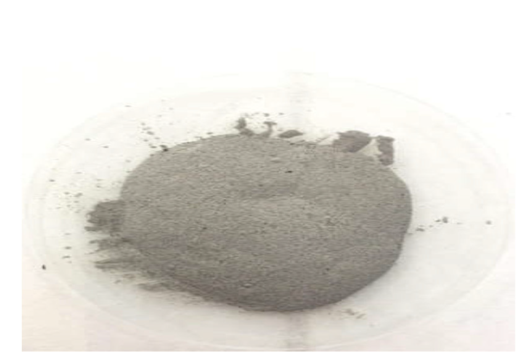
2.1. Raw Material

The main constituents are
  • Unsaturated polyester resin (UP) thermosetting.
It is a colorless viscous liquid, “unsaturated polyester” containing styrene or its strong smell of gas. The hardening is obtained by three-dimensional polymerization under the action of a catalytic system composed of two products:
-
The accelerator (cobalt octoate) gives the resin a pinkish hue, which partly disappears with the setting.
-
The catalyst: methyl ethyl ketone peroxide.
Contact, projection, injection, and filament winding can do its implementation.
The main characteristics of this resin are as follows:
·
Density at 20 °C …… 1.11 g/cm3
·
Viscosities at 25 °C ………………. 5–6 dPa.s approximately.
·
Dry shrinkage ………………………. 64%.
The properties of the hardened, unreinforced resin are as follows:
  • Mechanical properties
  • ISO 527 traction.
  • Stress at break............................. 55 MPa
  • Elongation at break......................... 2.2%
  • Bending ISO 178 40
  • Stress at break............................. 117 MPa
  • Modulus of elasticity................................... 3800 GPa
  • Physical properties at 20 °C
  • Freezing time: .............................................. 18 min
  • Freezing time at exothermic peak: ............ 15 min
  • Exothermic peak: ......................................... 138 °C
  • Industrial waste treated:
The fly ash (powder) ultra-supercritical power plant SAFIEC is the first coal-fired power plant in Africa to use ultra-supercritical technology (region Safi).

Preparing Waste Fly Ash (Powder)

Fly ash is the non-combustible particles entrained by smoke from the combustion of pulverized coal in thermal power plant boilers. To reduce air pollution, the stacks of these power plants are equipped with an Electrostatic precipitator (ESP), which captures the ash to prevent it from being dispersed in the atmosphere. The finesse Fly ash between 0, 5, to 300 µ, is shown in Figure 1.

2.2. Development of New Composite Material

The composite materials were made with coal fly ash, with a fineness of about 300 µm.
Predefined weighing of the fly ash (reinforcing filler) and the thermosetting resin (matrix), according to the specific volume of each mold used.
Knead the mixture with a paddle mixer.
Speed between 400 and 800 rpm, for 5 min.
Add 10 mL of the gas pedal using a 50 mL burette graduated at 0.1 mL, then mix for 1 min.
The mixture obtained is poured into a cylindrical mold whose dimensions are (D = 20 mm L = 23 cm) then left to harden in a thermostatic oven at 60 °C for 5 min.
The same operation is conducted for the paved mold whose dimensions are (25 × 25 × 1 (cm)).
A decisive step was to optimize the formulation of these composite materials in order to ensure good compactness, an adequate viscosity, and a satisfactory morphological aspect.
The two formulations selected for the study vary in their mass percentage of reinforcement, which is 50% and 60% coal fly ash.
After extracting the material, in Figure 2 and Figure 3 of several samples of the material, tests were carried out.

3. Characterization of Materials

The present work focuses on industrial waste, namely Fly ash (powder). We used Thermal Analysis (thermal conductivity) to characterize the Composite Material Fly ash and behavior to erosion, and Young’s module Compression test.

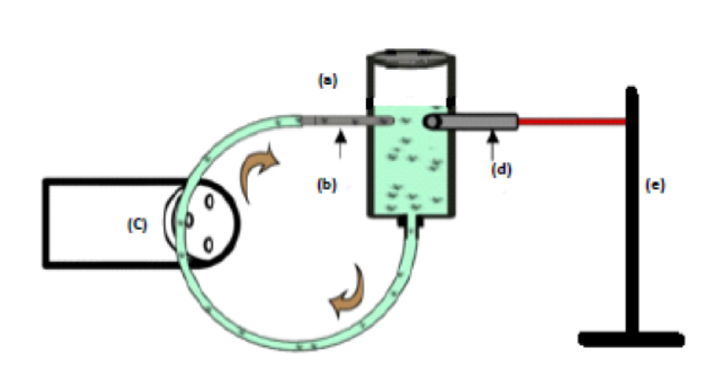
3.1. Thermal Analysis (Thermal Conductivity)

An experimental study was carried out to determine the thermal conductivity of the composite material. The principle of measuring the thermal conductivity of a large or small material is based on the permanent realization of a unidirectional heat flow through a sample placed in the isothermal box [31], between the isothermal box (A) and the constant flow heat source Q = U2/R whose energy emission is regulated by a rheostat (R). The heat emission is regulated in such a way that the temperature inside the housing of the isothermal box is slightly higher than the ambient temperature.
Once the steady-state is established, the temperature gradient at the center of the sample and the heating voltage are taken, and the formula below is used to deduce the value of the thermal conductivity λexp of the whole sample size:
λ exp = e S ( T c T f ) [ Q C ( T B T a ) ]
Equation (1) takes into account the following flows:
The thermal flow produced by the Joule effect through the heating resistance: Q = U2/R
Heat flow lost through the isothermal box: C(TB − TA); with C being the heat loss coefficient of the isothermal box.
Thermal flow transferred by conduction through the sample:
λ exp S ( T C T F ) e

3.2. Behavior to Erosion

The erosion-wear behavior study of the new composite material used a specific test bath dedicated to this type of test in order to stimulate and increase the aggressiveness of the application environment.
Erosion-wear problems occur in various industrial facilities, especially in factories using chemical substances; however, the origin of the raw material and the manufacturing techniques play a role in determining the behavior of the environment.
This process generates serious problems of surface condition, material damage caused by the presence of impurities such as chlorides, fluorides, and sulfides, and erosion phenomena [32,33]. Aggressive phosphoric and sulfuric media were chosen as test media to validate the potential industrial use of the material in pipelines and etching reactors. The abrasion study is illustrated in Figure 4.
The experimental set-up is inspired by the electrochemical set-up [34] and is formed by a cell (a) with a lateral opening for the introduction of a nozzle (b) and a working armature (d), which represents the composite material. In addition, a variable speed peristaltic pump (c) controlled the injection rate of the abrasive electrolyte containing SiC particles (Figure 5).
Before immersion in the cell (a), the composite material was treated by wet polishing with a series of SiC paper, decreasing particle size (180–1500), then rinsed with distilled water and dried in a stream- air.

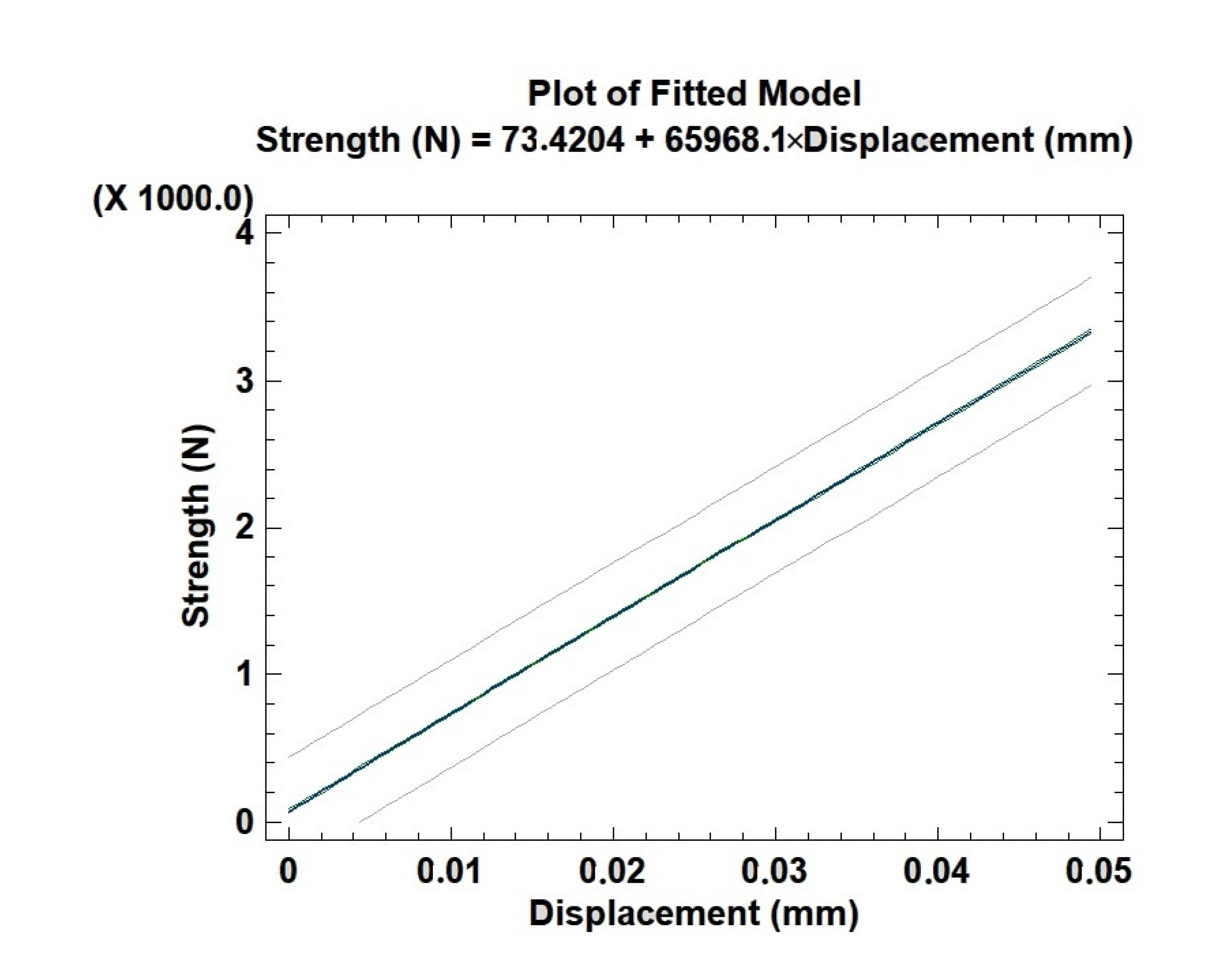
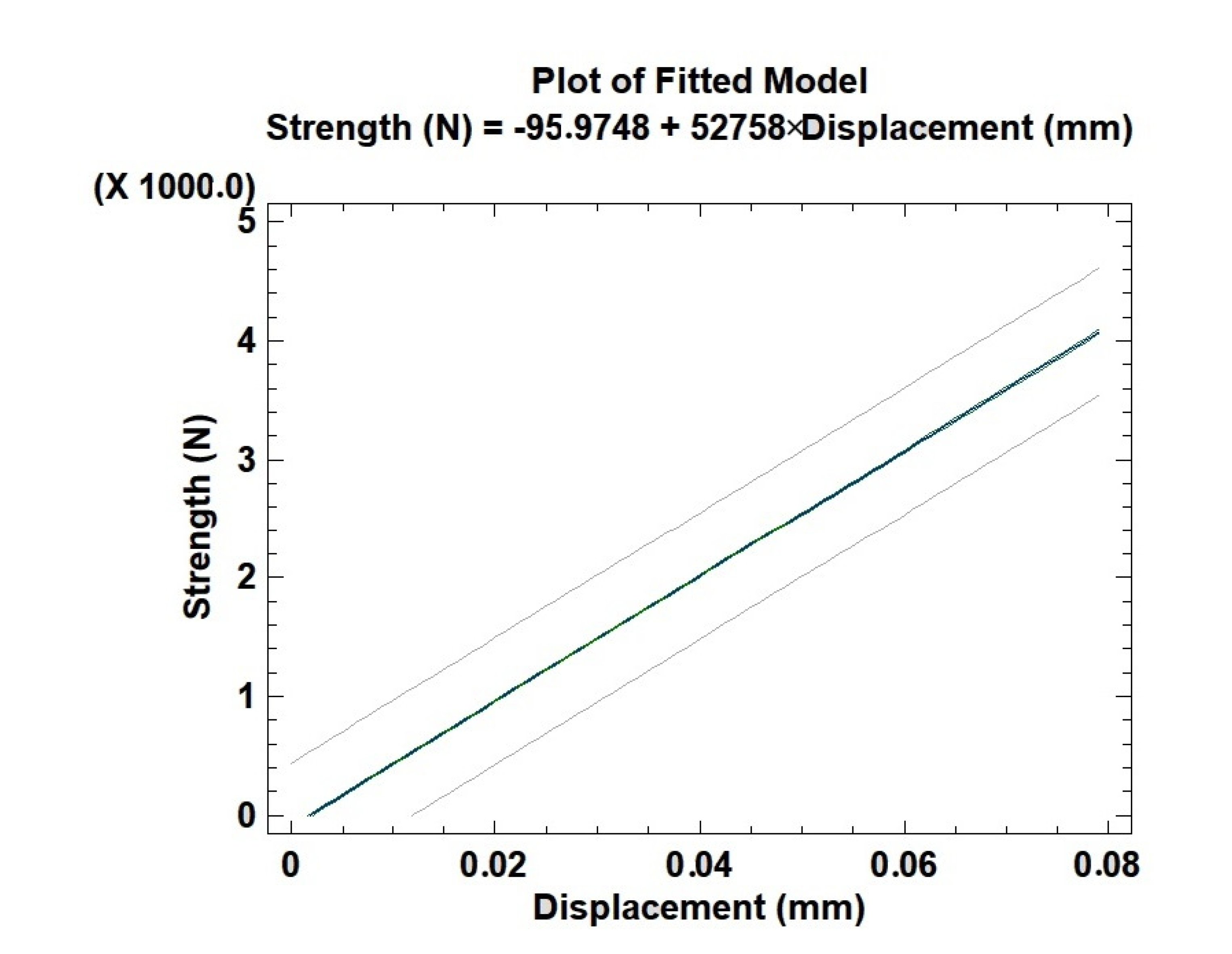
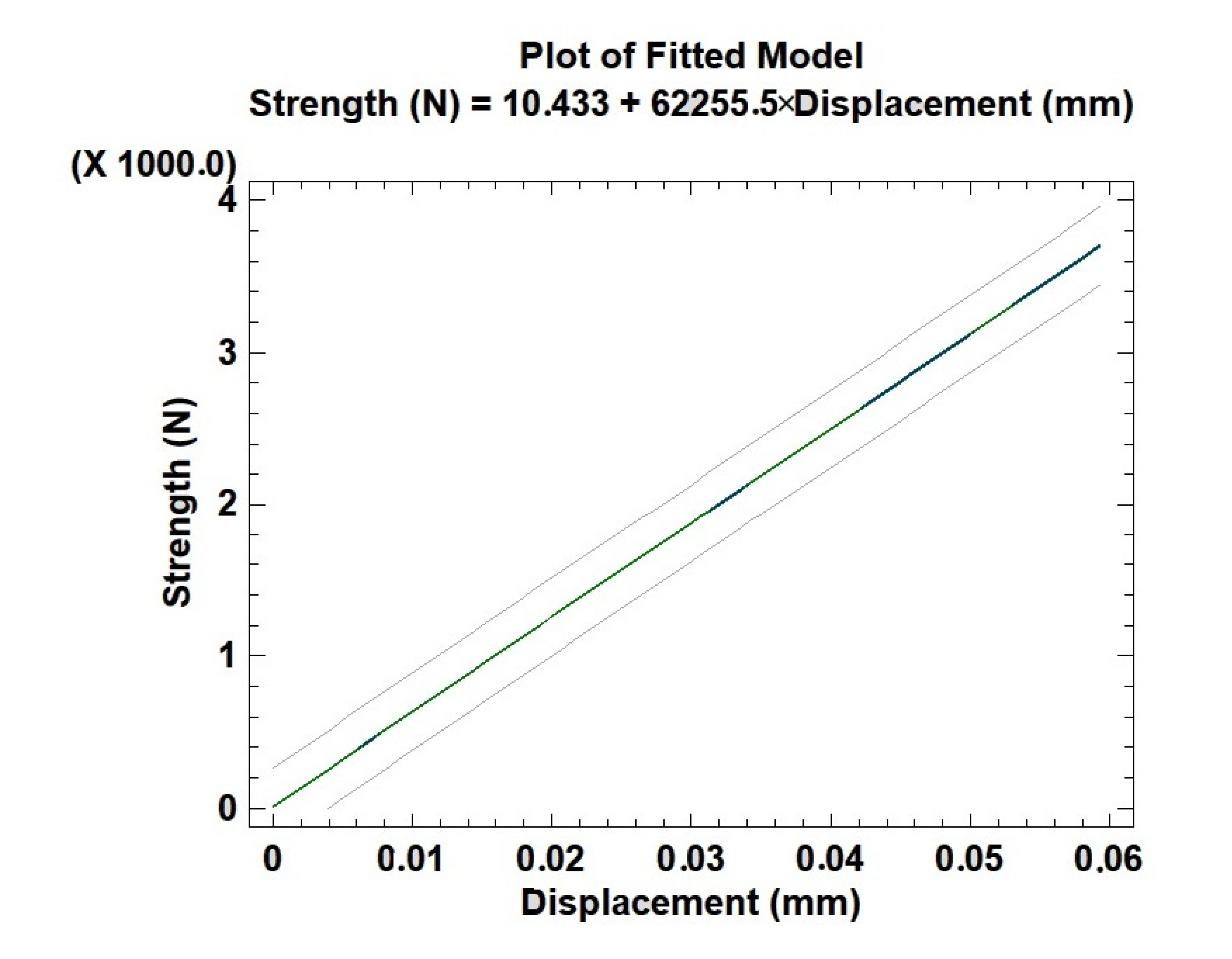
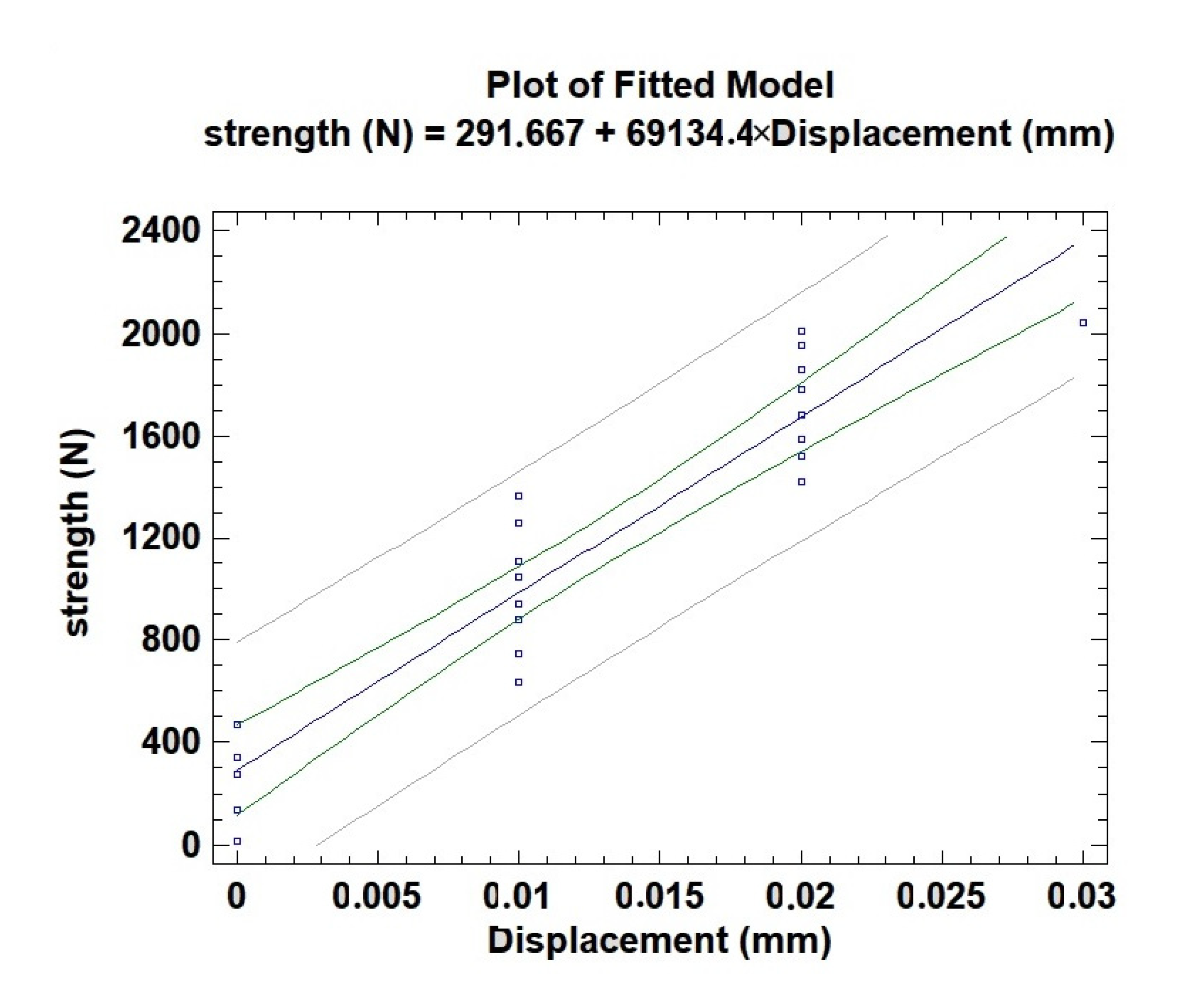
3.3. Young’s Module Compression Test

The mechanical test was used to study the positive or negative effects of “Fly ash (powder)” filler on the properties of the composite material. The composite materials were developed with different contents, 50%, and 60% white fracture, and each cylindrical composite material was cut separately into three sample thicknesses (70 mm).
To evaluate Young’s modulus, three samples were tested, and the average value was declared. The experiment was carried out under a quasi-static compression load for all the samples, using a standard computer-controlled mechanical testing machine EM00-EMR [35], equipped with the software LM Acq2V version 1.05.
The compression properties, such as Young’s modulus, are obtained from the linear regression compression curves using the Stat graphics software. These tests determined Young’s modulus E. Given by the following formula:
E = ( F e S 0 ) ( Δ L / L 0 ) = ( F e Δ L ) ( L 0 S 0 )
Fe: applied force. S0: initial section. L0: initial thickness. ΔL: lengthening.

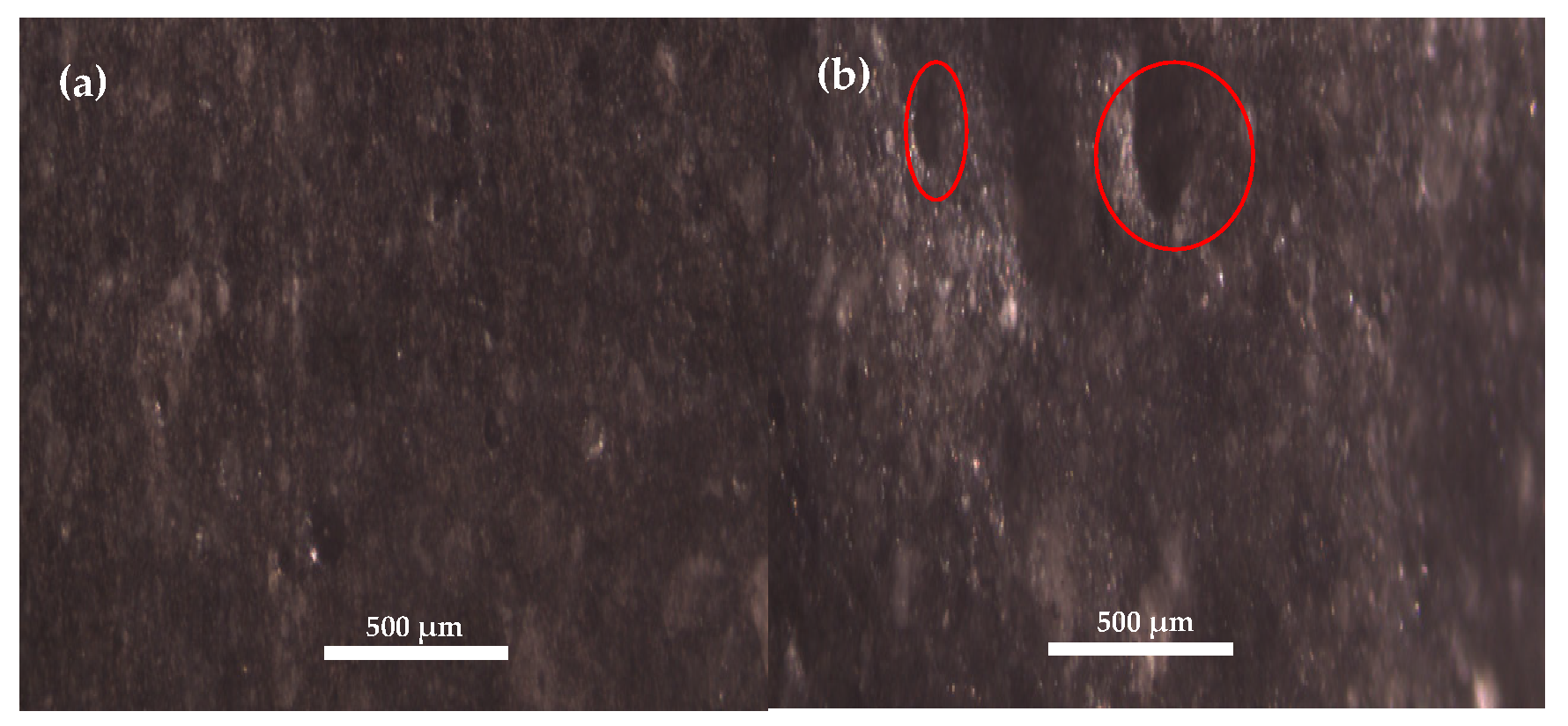
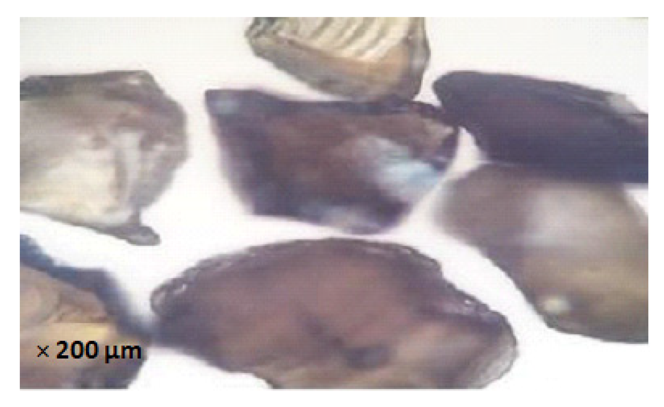
3.4. Scanning Electron Microscopy (SEM)

The observation of the sample is made using Scanning Electron Microscopy (SEM), which makes it possible to observe the texture and morphology of the fly ash and characterize the mineralogical assemblages.

3.5. Ray Diffraction X (DRX):

The Lab X-ray powder diffractometer, XRD-6100 Shimadzu apparatus, was used at a voltage of 40 KV and a current of 30 mA with a copper anti-cathode.
With a scanning speed of 0.02° s−1 in the angular range from 10 to 60° 2θ.
This diffractometer is equipped with:
-
Bragg-Brentano θ–2θ configuration goniometer
-
Scintillation detector; NaI type
-
Room temperature controller up to 1200 °C
-
Acquisition speed 0.05–25°/min (θ)
-
Measurement repeatability: 0.001° (2θ)

4. Results and Discussions

4.1. Thermal Analysis (Thermal Conductivity)

Thermal Analysis:
The applied flux equals 100 W. The two sides of the material (exterior and interior), placed in the isothermal chamber, are connected by thermometers. A heat flux equal to 100 W is applied for almost 40 min until the temperature stabilizes and the two temperatures of the Tint and Text sides are noted. The thermal conductivity is calculated based on the law of conduction heat transfer (Fourier’s law).
Table 2 below summarizes the results obtained during the experimental campaigns.
Experimental measurements of the thermal conductivity of composite materials based on the results presented in Table 3 have proven that this material has an insulating potential. As well as better thermal resistance to heat transmission (R), the latter is directly proportional to the thickness of the material and inversely proportional to the conductivity: R = d/λ.
The thermal resistance, R, shows a certain thickness of the respective material in order to not lose heat.
The results indicate that the thermal conductivity of the new composite material is low.
Materials frequently used for building insulation are chosen for their low conductivity and their ability to block heat flow.
Indeed, for mass ratios higher than 50%, the resulting material is competitive in terms of thermal conductivity, thermal resistance to heat transmission and has the advantage of being a cheaper product.
Table 4 shows the results obtained in a study of the thermal and mechanical properties of insulating concrete [36].
The analysis and comparison of the thermal conductivity results, grouped in Table 3 and Table 4, shows that the new fly ash composite material with the studied reinforcement percentages represents a potential gain in the insulation criteria; the thickness of the composite material is much smaller (1 cm) compared to the thickness of other materials. (The range is 10 cm to 18 cm).

4.2. Behavior to Erosion

The material sample was tested in a polluted 40-wt.% phosphoric acid solution with an addition of 4 wt.% of H2SO4 and 0.42 wt.% KCl with and without abrasive.
The surface of the material exposed to the medium was 0.5 cm2.
In all tests, the angle of incidence was 90°, and the concentration of abrasive particles was 24 g/L.
Figure 6b shows the surface of the composite material after the erosion test. This surface shows a slight degradation compared to the surface of the material in Figure 6a before the test.
This interpretation was confirmed by the results obtained from microscopic analysis and calculation of the weight before and after the test.
Mass loss is calculated by weighing the material before and after the erosion test. That is to say, a loss of mass of 0.98%.
The erosion behavior with the environmental aggressiveness factor, new composite material represents a high resistance and a significant potential.

4.3. SEM and DEX Methods

Scanning Electron Microscopy (SEM), Micrographs of the material or a material sample before erosion test.
Figure 7 shows the surface area of the composite material before erosion. The average EDX of the material surface indicates the presence of C, O, Al, and Si in a large percentage.
Scanning Electron Microscopy (SEM), Micrographs of the material or a material sample after erosion test.
Figure 8 shows the surface of the composite material after the erosion test; following the results obtained, the composite material presents a remarkable resistance and performance, this has been confirmed by the EDX average of the surface showing the presence of C, O, Al, and Si groups in a large percentage.

4.4. Young’s Module Compression Test

For all the samples, Young’s modulus comes from linear regression compression curves using the Stat graphics software. The two composite materials of compositions, 50%, 60% based on fly ash, are mentioned in the work.
Three samples for each proportion with the following dimensions: D = 20 mm, L = 70 mm, and the results of Young’s modulus (E) are together in Table 4.
As well as the graphics results, Figure 9, Figure 10, Figure 11, Figure 12, Figure 13 and Figure 14 are obtained after the treatment of the mechanical compression test data to deduce Young’s modulus.
For all samples, Young’s modulus is obtained from compression curves [37] with linear regression using Statgraphics software.
Here cited are the example of composite material samples at 50% and 60% fly ash reinforcement filler. The results of Young’s modulus are collated in Table 5.
From these graphs, reinforcement with ultra-supercritical power plant fly ash (powder) has a direct and positive effect on the mechanical properties of the new composite material. These results in a high Young’s modulus lead to improved stiffness. Similarly, for each composite material, a variation in Young’s modulus is observed as a function of the thickness of the sample. This is in full agreement with the results of the work on topological optimization methodology for maximizing the stiffness of composites [38].

5. Conclusions

The use of composite materials in industrial applications has tended to increase in recent years.
Hence, the interest in this new research work exploits and valorizes industrial waste (fly ash from staged combustion from an ultra-supercritical coal power plant) for the development of new composite materials for use in various fields and, more particularly, civil engineering.
A UP thermoset polymer was chosen as the binder for these reinforcements.
Optimization of the formulation became essential, and the modules developed were then subjected to physicochemical tests. Thermal conductivity, abrasion tests, and compression tests revealed good toughness and high resistance to moisture, environmental stresses, and mechanical strain.
The experimental techniques used highlighted the properties of this new composite material. This new composite material represents a sustainable and environmental solution through the recovery of construction waste. The results of the present study have highlighted the performance and stiffness of the new composite material, which has evolved through the evolution of Young’s modulus. These vary progressively with the filler content.
The observed performance of these materials has prompted their development in the formulation of other products under evaluation.

Author Contributions

Conceptualization, M.E.K. and R.B.; methodology, M.E.K. and R.B.; software, M.E.K., A.H., C.E. and R.B.; validation, M.E.K., A.H., C.E. and R.B.; formal analysis, M.E.K., S.E. and C.E.; investigation, M.E.K. and R.B.; resources, M.E.K., R.B., C.E., S.E., A.H. and A.G.; data curation, M.E.K., S.E. and C.E.; writing—original draft preparation, M.E.K.; writing—review and editing, M.E.K., R.B., S.E. and C.E.; visualization, M.E.K., R.B., S.E. and C.E.; supervision, M.E.K. and R.B., A.H. and A.G.; project administration, M.E.K. and R.B.; no funding acquisition. All authors have read and agreed to the published version of the manuscript.

Funding

This research received no external funding.

Data Availability Statement

Some or all data, models, or code generated or used during the study are available from the corresponding author by request. 1. Analysis and chemical composition of this new material. 2. The statistical data of the different linear regression of Young’s modulus of the new composite material.

Conflicts of Interest

The authors declare no conflict of interest.

References

  1. Ahmaruzzaman, M. A review on the utilization of fly ash. Prog. Energy Combust. Sci. 2010, 36, 327–363. [Google Scholar] [CrossRef]
  2. Shen, Z.; Li, L.; Wang, Z.; Cai, C.; Yu, X. Cenospheres from Coal Ash and Their Application; National Defense Press: Beijing, China, 2008; p. 254. [Google Scholar]
  3. Lighty, J.S.; Veranth, J.M.; Sarofim, A.F. Combustion Aerosols: Factors Governing Their Size and Composition and Implications to Human Health. J. Air Waste Manag. Assoc. 2000, 50, 1565–1618. [Google Scholar] [CrossRef]
  4. Bian, X.; Xie, Q.; Zhao, C. Technology to Transfer Coal-Based Solid Wastes to Resources; Chemical Industry Press: Beijing, China, 2005; p. 294. [Google Scholar]
  5. Li, W.; Zhai, J.; Xu, Y.; Tu, J.; Lin, Y. Study on the characteristics and genetic mechanism of microspheriods in cpfa. Environ. Eng. 1997, 15, 51–56. [Google Scholar]
  6. Lauf, R.J. Cenospheres in fly ash and conditions favouring their formation. Fuel 1981, 60, 1177–1179. [Google Scholar] [CrossRef]
  7. Ngu, L.-N.; Wu, H.; Zhang, D.-K. Characterization of Ash Cenospheres in Fly Ash from Australian Power Stations. Energy Fuels 2007, 21, 3437–3445. [Google Scholar] [CrossRef]
  8. Hong, X.U.; Xiao-min, C.H.E.N.; Guang-ping, X.U. Study on the Characteristics and Genetic Mechanism of Microspheroids in CPFA from Huaneng Nanjing Electric Power Plant. Geol. J. China Univ. 2000, 1, 80–86. [Google Scholar]
  9. Vassilev, S.V.; Vassileva, C.G. A new approach for the classification of coal fly ashes based on their origin, composition, properties, and behavior. Fuel 2007, 86, 1490–1512. [Google Scholar] [CrossRef]
  10. Ramme, B.W.; Tharaniyil, M.P. Coal Combustion Products Utilization Handbook, 3rd ed.; Wisconsin Electric Power Company: Milwaukee, WI, USA, 2004. [Google Scholar]
  11. NF EN 197-1. French and European standards for products or uses with coal fly ash: Cement-Part 1: Composition, specifications and conformity criteria for current cements. 2001. Available online: https://standards.iteh.ai/catalog/standards/sist/00e7c857-98b1-4132-b9ec-9cf156a8dfc3/sist-en-197-1-2001-opra2-2006 (accessed on 3 June 2021).
  12. Tikalsky, P.J.; Carrasquillo, R.L. The Effect of Fly Ash on the Sulfate Resistance of Concrete; Research Report 481-5; Center for Transportation Research: Austin, TX, USA, 1989; pp. 106–118. [Google Scholar]
  13. Harris, B.; Dorey, S.E.; Cooke, R.G. Strength and Toughness of Fibre Composites. Compos. Sci. Technol. 1988, 31, 121–142. [Google Scholar] [CrossRef]
  14. Sow, M. Realization of Eco-Cements by the Recovery of Unconventional Coal Fly Ash from Spreader Stoker Thermal Power Plants. Ph.D. Thesis, University of Toulouse, Toulouse, France, 2016; pp. 25–26. [Google Scholar]
  15. Alheyen, S. Synthesis, Characterization, Microstructure and Durability of Fly Ash-based Geopolymers. Doctoral Dissertation, Mohammed University 5, Rabat, Morocco, 2017; pp. 53–55. [Google Scholar]
  16. Zhou, L.; Xu, G.; Zhao, S.; Xu, C.; Yang, Y. Parametric analysis and process optimization of steam cycle in double reheat ultra-supercritical power plants. Appl. Therm. Eng. 2016, 99, 652–660. [Google Scholar] [CrossRef]
  17. Sow, M. Realization of Eco-Cements by the Valorization of Non-Conventional Coal Fly Ash from Spreader Stoker Thermal Power Plants. Ph.D. Thesis, University of Toulouse, Toulouse, France, 2016; pp. 25–26. [Google Scholar]
  18. Kashif, M.; Awan, M.B.; Nawaz, S.; Amjad, M.; Talib, B.; Farooq, M.; Rehan, M. Untapped renewable energy potential of crop residues in Pakistan: Challenges and future directions. J. Environ. Manag. 2020, 256, 109924. [Google Scholar] [CrossRef]
  19. Osborne, D.G.; Sharples, M.; Lien, L.; Schumacher, G.; Babich, A.; Harris, D.; Carras, J. Future directions toward more efficient and cleaner use of coal. In The Coal Handbook: Towards Cleaner Production; Elsevier: Amsterdam, The Netherlands, 2013; pp. 497–528. [Google Scholar]
  20. Afechkar, M.; Nahhass, M. Valorisation des cendres volantes dans le domaine routier (terrassements et couches de chaussées); Laboratoire du CNER; 2004; p. 4. Available online: http://www.ampcr.ma/actes/7eme_congres_national_de_la_route/CONGRE/TH4/TH4_4.pdf (accessed on 3 June 2021).
  21. 21. Ayrinhac. Recovery of Fly Ash from a Fluidized Bed Boiler Circulating in the Civil Engineering Sector. Doctoral Dissertation, National Institute of Applied Sciences of Toulouse, Toulouse, France, 2005; p. 11.
  22. El Alouani, M.; Alehyen, S.; El Achouri, M.; Taibi, M. Comparative study of the adsorption of micropollutant contained in aqueous phase using coal fly ash and activated coal fly ash: Kinetic and isotherm studies. Chem. Data Collect. 2019, 23, 100265. [Google Scholar] [CrossRef]
  23. Mohanty, S.; Chugh, Y. Development of fly ash-based automotive brake lining. Tribol. Int. 2007, 40, 1217–1224. [Google Scholar] [CrossRef]
  24. Zhuang, X.Y.; Chen, L.; Komarneni, S.; Zhou, C.H.; Tong, D.S.; Yang, H.M.; Yu, W.H.; Wang, H. Fly ash-based geopolymer: Clean production, properties and applications. J. Clean. Prod. 2016, 125, 253–267. [Google Scholar] [CrossRef]
  25. Viswanathan, R.; Coleman, K.; Rao, U. Materials for ultra-supercritical coal-fired power plant boilers. Int. J. Press. Vessel. Pip. 2006, 83, 778–783. [Google Scholar] [CrossRef]
  26. Stein-Brzozowska, G.; Flórez, D.M.; Maier, J.; Scheffknecht, G. Nickel-base superalloys for ultra-supercritical coal-fired power plants: Fireside corrosion. Laboratory studies and power plant exposures. Fuel 2013, 108, 521–533. [Google Scholar] [CrossRef]
  27. Fan, H.; Zhang, Z.; Dong, J.; Xu, W. China’s R&D of advanced ultra-supercritical coal-fired power generation for addressing climate change. Therm. Sci. Eng. Prog. 2018, 5, 364–371. [Google Scholar]
  28. Rocha, D.H.; Silva, R.J. Exergoenvironmental analysis of a ultra-supercritical coal-fired power plant. J. Clean. Prod. 2019, 231, 671–682. [Google Scholar] [CrossRef]
  29. Zhu, B.T.; Zhao, Y. Development of ultra-supercritical power generation technology in China. Huadian Technol. 2008, 30, 1–5. [Google Scholar]
  30. Castello, P.; Guttmann, V.; Farr, N.; Smith, G. Laboratory-simulated fuel-ash corrosion of superheater tubes in coal-fired ultra-supercritical-boilers. Mater. Corros. 2000, 51, 786–790. [Google Scholar] [CrossRef]
  31. Boulaoued, I.; Amara, I.; Mhimid, A. Experimental determination of thermal conductivity and diffusivity of new building insulating materials. Int. J. Heat Technol. 2016, 34, 325–331. [Google Scholar] [CrossRef]
  32. Hajji, M.A. Corrosion et Corrosion-Abrasion d’alliage. Fac. Sci. Rabat 1996, 35–37. [Google Scholar]
  33. Guenbour, A.; Faucheu, J.; Bachir, A.B. On the mechanism for improved passivation by addition of molybdenum to austenitic stainless steels in O-phosphoric acid. Corrosion 1998, 44, 214–221. [Google Scholar] [CrossRef]
  34. Skal, S.; Kerroum, Y.; Guenbour, A.; Bellaouchou, A.; Tabyaoui, H.; Idrissi, H.; Zarrouk, A.; García-Antón, J. Effect of abrasive particles on electrochemical behaviour of passive film formed on Alloy 59 in contaminated phosphoric acid. JMES 2017, 8, 3234–3246. [Google Scholar]
  35. Ennawaoui, C.; Lifi, H.; Hajjaji, A.; Samuel, C.; Rguiti, M.; Touhtouh, S.; Courtois, C. Dielectric and mechanical optimization properties of porous poly (ethylene-co-vinyl acetate) copolymer films for pseudo-piezoelectric effect. Polym. Eng. Sci. 2019, 59, 1455–1461. [Google Scholar] [CrossRef]
  36. Mohaine, S. Etude des Propriétés Thermiques et Mécaniques des Bétons Isolants Structurels Incorporant des Cénosphères. Doctoral Dissertation, Génie civil. École centrale de Nantes, Nantes, France, 2018; p. 33. (In French). [Google Scholar]
  37. Kanzaoui, M.E.L.; Boussen, R.; Hajjaji, A.; Guenbour, A. Development and study of mechanical behaviour reinforcing composites by waste BTP. In Proceedings of the MATEC Web of Conferences on Development and Study of Mechanical Behaviour Reinforcing Compo-sites by Waste BTP, Rabat, Morocco, 22–25 November 2018. [Google Scholar]
  38. Long, K.; Du, X.; Xu, S.; Xie, Y.M. Composite Structures, Maximizing the effective Young’s modulus of a composite material by exploiting the Poisson effect. Compos. Struct. 2016, 153, 593–600. [Google Scholar] [CrossRef]
Figure 1. Fly ash (powder) ultra-supercritical power plant SAFIEC.
Jcs 05 00151 g001
Figure 2. Paving Composite Material Fly ash.
Jcs 05 00151 g002
Figure 3. Armature Composite Material Fly ash.
Jcs 05 00151 g003
Figure 4. Abrasion-corrosion test: (a) Cell, (b) nozzle, (c) peristaltic pump. (d) The Composite Material Fly ash, (e) support.
Jcs 05 00151 g004
Figure 5. Morphology of SiC particles using corrosion-abrasion.
Jcs 05 00151 g005
Figure 6. Micrographs of sample before test (a) and after test in the polluted phosphoric acid with particles abrasives SiC (b).
Jcs 05 00151 g006
Figure 7. Representative SEM images and EDX elemental analysis surface of composite material before erosion test.
Jcs 05 00151 g007
Figure 8. Representative SEM image and EDX elemental analysis surface of composite material after erosion test.
Jcs 05 00151 g008
Figure 9. Graph of the adjusted model Test 1. Composite material 50% fly ash (D: 20 mm/E: 70 mm).
Jcs 05 00151 g009
Figure 10. Graph of the adjusted model Test 2. Composite material 50% fly ash (D: 20 mm/E: 70 mm).
Jcs 05 00151 g010
Figure 11. Graph of the adjusted model Test 3. Composite material 50% fly ash (D: 20 mm/E: 70 mm).
Jcs 05 00151 g011
Figure 12. Graph of the adjusted model Test 1. Composite material 60% fly ash (D: 20 mm/E: 70 mm).
Jcs 05 00151 g012
Figure 13. Graph of the adjusted model Test 2. Composite material 60% fly ash (D: 20 mm/E: 70 mm).
Jcs 05 00151 g013
Figure 14. Graph of the adjusted model Test 3. Composite material 60% fly ash (D: 20 mm/E: 70 mm).
Jcs 05 00151 g014
Table 1. Chemical composition of Coal fly ash [20].
ElementMass Percent (%)
SiO243–54%
Al2O322–32%
Fe2O3 + TiO24–15%
CaO1–8%
MgO1–3%
K2O2−5%
Na2O0.5–1%
SO30.2−2%
Table 2. The results of thermal analysis.
1st Material2nd Material
● Paving: 50% Fly Ash Dimensions:
25 × 25 × 1 (cm)
● Paving: 60% Fly Ash Dimensions:
25 × 25 × 1 (cm)
Test number123123
Thickness (cm)11
Tint (°K)320.65320.75320.95315.43316.46315.25
Text (°K)301.46299.75301.35300.35300.25301.00
Thermal
Conductivity (W/m.°K)
0.8340.7620.8161.0610.9871.123
Table 3. The results of thermal analysis.
1st Material2nd Material
• Paving: 50% Fly Ash Dimensions: (cm)• Paving: 60% Fly Ash Dimensions: (cm)
25 × 25 × 125 × 25 × 1
Thickness (cm)11
Average
Thermal Conductivity (W/m. °K)
0.8041.057
Standard deviation (σ)0.0300.055
Table 4. Properties of the materials used for the model adopted from the facade/intermediate floor connection.
DesignationMaterialConductivity Thermal (W/m.K)Thickness (cm)
FloorSolid concrete218
Facade veilconcrete or BISVariable (0.4 or 0.8)15
InsulatingGlass wool0.03810
Table 5. Synthesis of compression mechanical test results.
Young’s Modulus in (GPa)
MaterialTest 1Test 2Test 3
Composite
50% Fly ash14.8513.2414.7
60% Fly ash19.8214.1313.87
Publisher’s Note: MDPI stays neutral with regard to jurisdictional claims in published maps and institutional affiliations.

