1. Introduction
Fibre reinforced polymer (FRP) composites have significantly increased in usage amongst structures in automotive, aerospace and wind energy industries. FRP composites have even shown advantageous when utilised as reinforcement in rubberised concrete sleepers in railway applications [
1]. The main advantages of FRP composite materials for structural applications is their excellent stiffness and strength to weight ratio as well as corrosion and fatigue resistance [
2] benefits over metallic counterparts. Despite their superior properties in the direction of the fibre reinforcement, laminated composites are weak in the out-of-plane-strength. That makes them susceptible to failure under transverse static and dynamic loading which are the major concerns in FRP composite laminated structures design [
3]. Due to their high speed of service, such structures are occasionally subjected to high velocity foreign object impacts. This can include debris from the runway hitting an aircraft during landing or take-off or floating parts in the track during an automotive race striking the vehicle. Structural integrity justification has to take into consideration all such effects before setting a product in service. However, the experimental route is rather costly and hardly an easily reproducible way of testing and characterising the behaviour of various materials and design solutions. Industry has turned its focus into partially employing numerical simulations for product certification.
Various simulation methods have been developed for impact on FRP composites, most of them in the micro and mesoscale level. To achieve a correct impact response of an FRP composite plate, the simulation procedure must be capable to capture different failure mechanisms arising from an impact event; intra-ply failure like fibre fracture and matrix cracking as well as inter-ply failure-like delamination. To achieve this, researchers often simulate a full composite laminate using a ply-by-ply approach where individual or bulk layers of a laminate stack are modelled using 3D continuum or shell elements. To capture progressive failure of the plies, continuum damage model (CDM) methods are adopted which degrade elements of a ply layer based on a suitable failure criterion model and the interface between each layer is simulated using cohesive zone modelling (CZM) methods. Numerous examples of this particular approach has been shown to simulate impact events [
4,
5,
6,
7,
8]. Woven composites, which have proven to be more competitive than uni-directional (UD) laminates in impact resistance [
9], are more challenging in the field of simulation modelling due to their complex woven fibre geometry. To achieve models that differentiate the warp and weft fibres, resin rich zones and the interfaces in-between is impractical. Even so, researchers often treat woven layers as a single bulk material with effective stiffness and strength properties similar to UD laminate layers. Due to the high level of detail in these modelling schemes, the computational cost of the simulations is extremely high and impractical when it comes to simulating larger structures subjected to impact events.
The main objective of the work presented herein is to investigate a macroscale modelling approach to simulate the damage formed on woven composites under high speed projectile impact also called ballistic impact. This will be achieved by treating the stacked woven composite laminate material as a single bulk material, with a single failure criterion with CDM used for simulating the total accumulated damage. The merit of this low-fidelity (LF) procedure will be compared to a standard high-fidelity (HF) ply-by-ply progressive failure with CZM to capture delamination. The key novelty of this work is the comparison of the two schemes in terms of computational speeds and accuracy in damage prediction. This type of comparison is not available in literature under a single investigation, since most research employ a single detailed modelling procedure often with bespoke user materials specifically written for it. To avoid this and make this work universal for both academic and industrial readers, commercial FE software package in LS-DYNA will be used in conjunction with built-in composite material model cards.
To aid with this study, experimental impacts were performed on woven composite plates to be used as benchmark cases for the numerical simulations. The experimental setup consisted of a gas gun able to project steel balls onto composite plate targets at various velocities prior and after the ballistic limit where full plate perforation was achieved.
2. Experimental Methods
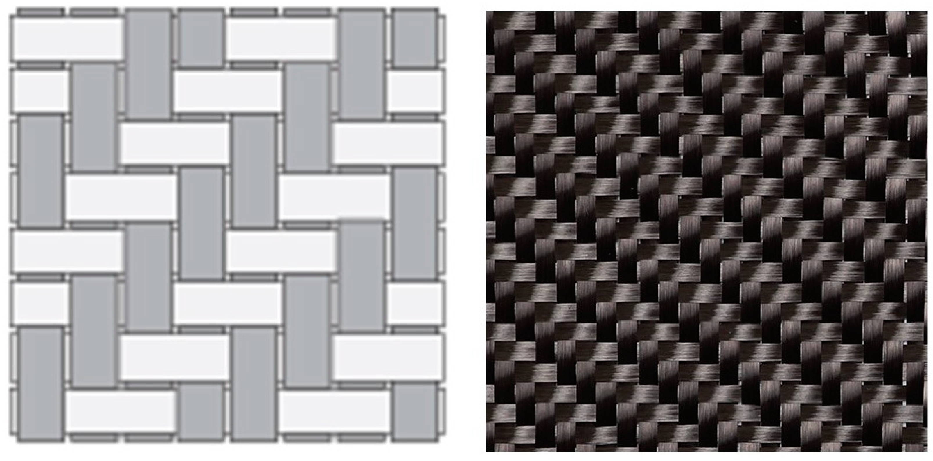
The carbon fibre reinforced plastic (CFRP) composite material used for the ballistic impact experiments, was sourced from SHD Composites materials producer, denominated as MTC510-C380T-T700-12K-38%RW. This is a toughened epoxy resin (MTC510) pre-impregnated fibre-matrix material system, reinforced by high strength carbon fibres (T700/12K). The fibres were twilled in a 2 × 2 weave style, shown in
Figure 1, resulting in a fabric of 380 g/m
2 areal weight. The mechanical properties of the CFRP composite lamina are provided by the manufacturer, presented in
Table 1. Plates of two different lay-ups were studied for the impact testing. The first configuration was orthotropic, having a lay-up arrangement of [(0/90)
4]
s denominated as [(0/90)] onwards for simplicity, while the second was quasi-isotropic with a layup arrangement of [(±45),(0/90),(±45),(0/90)]
s, denominated as [(±45)] onwards. Both configurations consisted of eight layers in total, providing specimens of nominal thickness of 3.6 mm. In terms of the manufacturing procedure followed, the woven pre-impregnated layers were hand laid to create two 300 mm square laminate stacks. A de-bulking procedure under vacuum took place for every four plies, to consolidate the lay-up and remove all air trapped in the resin matrix. The laminates were cured in an autoclave according to the manufacturer specifications. Out of the two original 300 mm cured plates, four 150 mm square panels were machined, resulting to eight test specimens in total, four for each configuration.
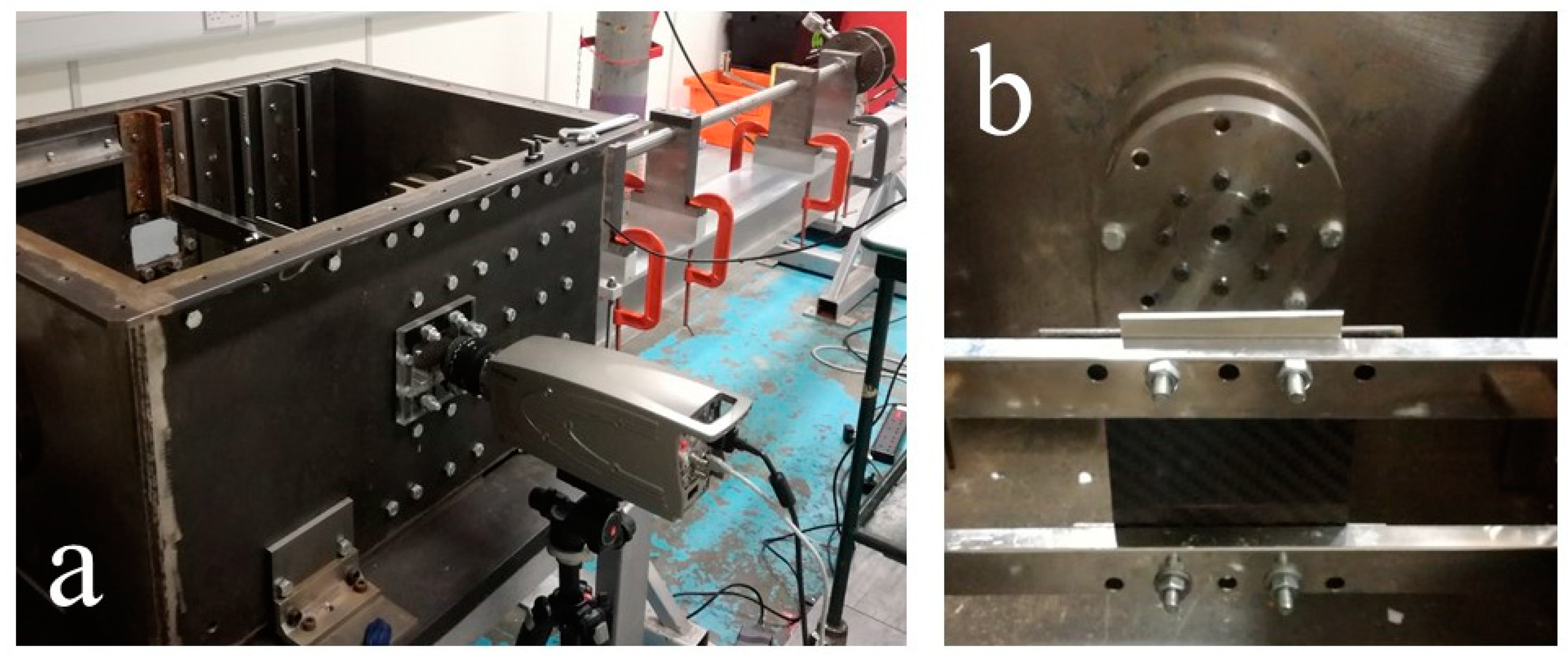
The ballistic impact experiments were conducted using a pressurised gas-gun set up as shown on
Figure 2a. The aim of this experimental tests is to collect empirical data to assist with the low and high-fidelity modelling procedures. To maintain simplicity in the test procedure, spherical steel projectile were used instead of more complicated projectiles defined in available test standards. The impactors were stainless-steel balls with diameter of 12 mm and mass of 7 g. The balls were loaded into the gun with the help of a 50 g polycarbonate sabot, placed at the end of the gun barrel. During the firing stage, the sabot was separated from the steel balls upon entry into the impact chamber from the exit nozzle. This effectively allowed only the steel ball to impact the FRP panels. The total mass of the sabot and steel ball (57 g) was used to calculate the gas pressure in the gun to achieve the desired nominal impact velocity. The 150 mm square panels were mounted inside the impact chamber by clamping in the top and the bottom side, as shown in
Figure 2b. The velocity of the impact was measured by a laser gate and the whole incident was captured with a high-speed camera. Limitations in number of samples only allowed for four different impact velocities per plate type. To generate useful trend, the impact velocities for the experiment were selected under, close to, and over the ballistic limit signified by plate perforation, to investigate the capability of the numerical model to predict the damage in each case. The ballistic limit was identified to be in the vicinity of 100 m/s. The velocity of the impactor was easily manipulated by the pressure of the gas in the gas-gun. The final parameters selected for the experiments are given on
Table 2. There were small deviations between the predicted and actual velocity impacting the targets. The actual velocities measured by the laser gate along with the associated energies of each impact are summarised in the results section of this work.
3. Numerical Methods
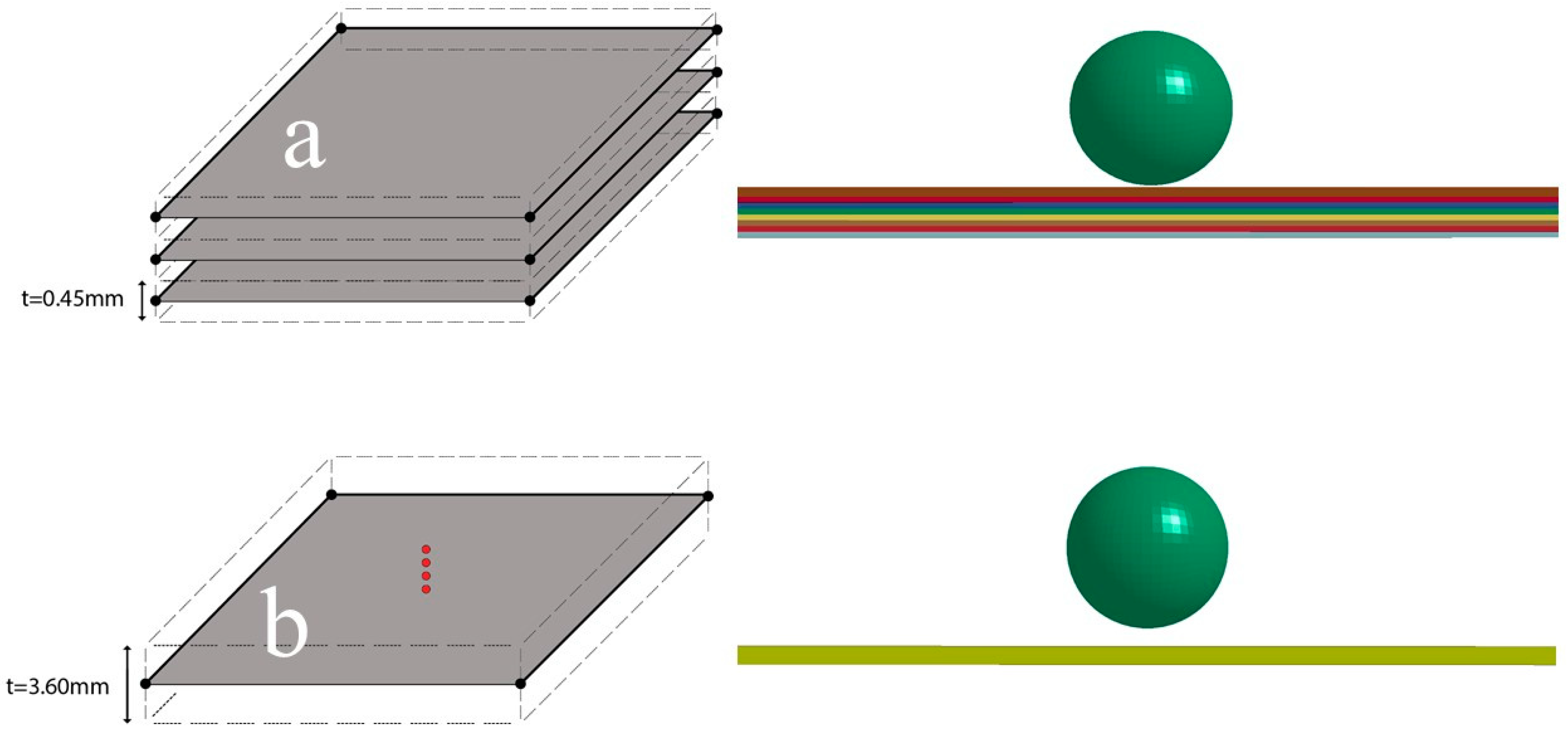
Numerical simulations have been carried out using the commercial software LS-DYNA©. A high fidelity (HF) model version of the composite panels was created, where each ply was represented as an individual layer of shell elements with two integration points along the thickness direction for each element layer, shown in
Figure 3a. Each layer was modelled with 0.5 mm size square solid shell elements, fully integrated formulation and a shell thickness of 0.45 mm per layer. The layers were bonded with each other with the TIEBREAK contact definition with CZM applied. The modelling approach was computational costly, but it allowed for the study of delamination between individual plies of the panel. For the lower fidelity (LF) model, a single shell elements layer was created with eight integration points through the thickness, each representing a single lamina ply, shown in
Figure 3b. Similarly, to the HF model, fully integrated 0.5 mm square solid shell elements were defined.
Progressive damage modelling was implemented through in-plane continuum damage modelling on the woven fabric and discrete damage modelling for the inter laminar regions. Material card MAT_54 was used for modelling the woven fabric, contained progressive failure modelling to simulate orthotropic composite laminates. The material model MAT_54 was originally created for simulating unidirectional composite laminates but can be also applied on fabric composites following some assumptions. The woven lamina was considered an orthotropic material in which the fibres are dominating the strength in both longitudinal and transverse direction. In the case of the 2 × 2 twill weave, the properties of the material were considered the same in both directions. In the elastic behaviour regime prior to damage initiation, the model used the stress–strain equations developed by Chang and Chang [
10]. The Chang-Chang failure criterion used in this material model can be calibrated to describe the shape of the post initiation failure response, similar to plasticity in metals, hence the nonlinearity of the post-failure of a ply can be captured [
11]. The failure criterion is similar to Hashin failure criterion [
12] which includes four failure modes for the longitudinal and transverse direction for both tensile and compressive loads. LS-DYNA uses four history variables to express this criterion as failure flags which express tension and compression failure for fibre and matrix direction respectively. MAT_54 model in LS-DYNA has both stress and strain dependent post failure response allowing the user to define the shape of the progressive failure response of a continuum element. The user can then define whether the stiffness of the continuum element degrades to zero in a linear form or it assumes a stepwise form, akin to metal plasticity, where the stiffness is kept constant for increasing strain, until it reaches the final failure strain, where the element stiffness is degraded completely. In the transverse direction, the model allows the user to define only one strain failure parameter for both tension and compression and two different strength values which were the major drawbacks in the use of the MAT_54 model in describing the behaviour of fabric composite materials. Due to the limitation of being able to use only one parameter for the transverse failure behaviour of the material it was decided to input the largest of the two strain to failure values. Another drawback is that the model allows for input of a single modulus of elasticity for tension and compression. The material under investigation exhibits a small difference in the moduli of about 12% between the two directions. In our numerical study, the larger value of the two was used, hence providing a slightly less compliant behaviour for the layers under compression. The strength and strain input values of the model are shown on
Table 3.
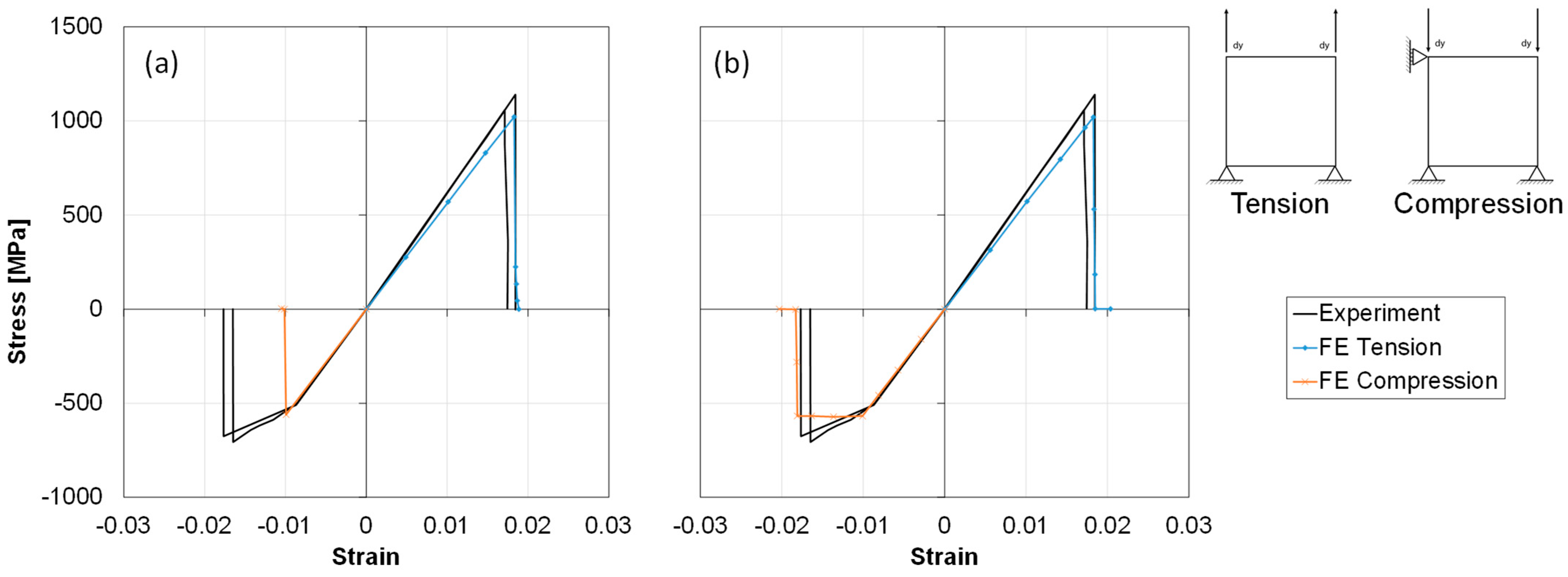
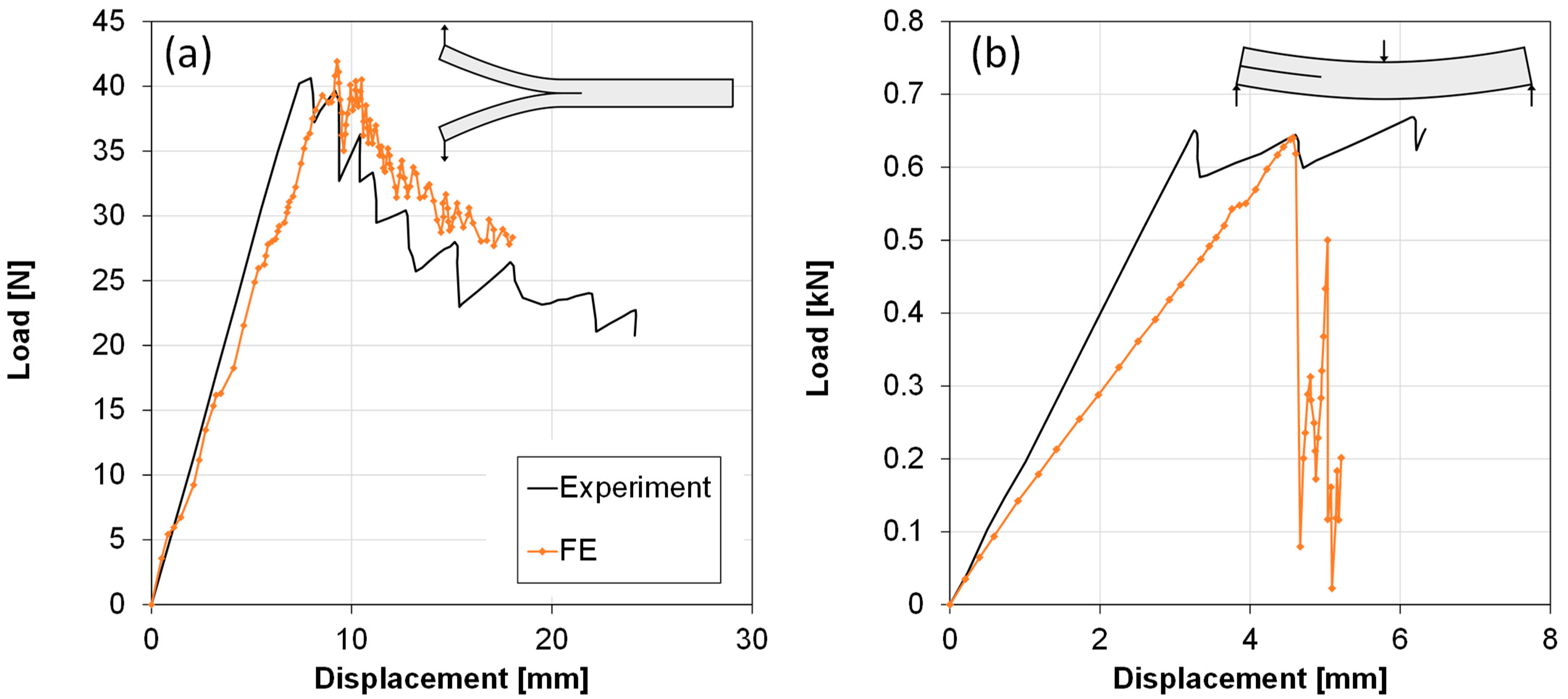
To characterise and calibrate the behaviour of the material model, single element simulations have been conducted using the fully integrated shell element ELFORM 16. The results were put in comparison with experimental data from literature [
13] to test the accuracy of the model at the element level where good agreement between experimental and simulation results was achieved as shown in
Figure 4. Despite the drawback of only one strain to failure parameter in the transverse direction, the plastic behaviour of the material model until failure did not notably deviate from the experimental one. Adjusting the strain to failure parameters (DFAILT, DFAILC and DFAILM) effectively changes the fall of the slope post failure initiation (peak stress). The woven lamina can be considered as an orthotropic material in which the fibres are dominating the strength in both longitudinal and transverse direction, resulting in equal properties in these directions. This can be controlled by the DFAILM parameter, which originally describes the matrix behaviour of the UD material, only because UD composites tend to be matrix dominated in the transverse direction. In the case of the 2 × 2 twill weave, the properties of the material were considered the same in both directions. The limitation of having only one value (DFAILM) for the transverse failure behaviour of the material was overcame by inputting the biggest of the two strain to failure values (i.e., E22 compression strain to failure
Figure 4b.)
For the inter laminar bond at ply interface, the HF models, automatic one-way surface-to-surface TIEBREAK contact type was defined. The TIEBREAK contact allowed the connections to transfer both compressive and tensile forces [
14]. The loads during contact were transferred from the slave nodes to the master segments through simple linear spring equations. CZM in the TIEBREAK contacts are described by a bilinear traction separation law, including a strength-based mixed mode failure initiation criterion between the surfaces and a quadratic mixed mode delamination criterion. For the damage initiation strength and failure propagation fracture toughness values, experimentally derived values from Kuwata and Hogg [
15,
16] were used, where the woven FRP laminates are similar to those used in this study. The calibrated models are shown in
Figure 5 which highlight the well matching response for double cantilever beam (DCB) tests and slight deviation with the end notch flexure (ENF) test in stiffness but close delamination initiation load. The CZM properties were calibrated with the experimental DCB and ENF tests results from the above-mentioned papers shown in
Table 4.
5. Discussion
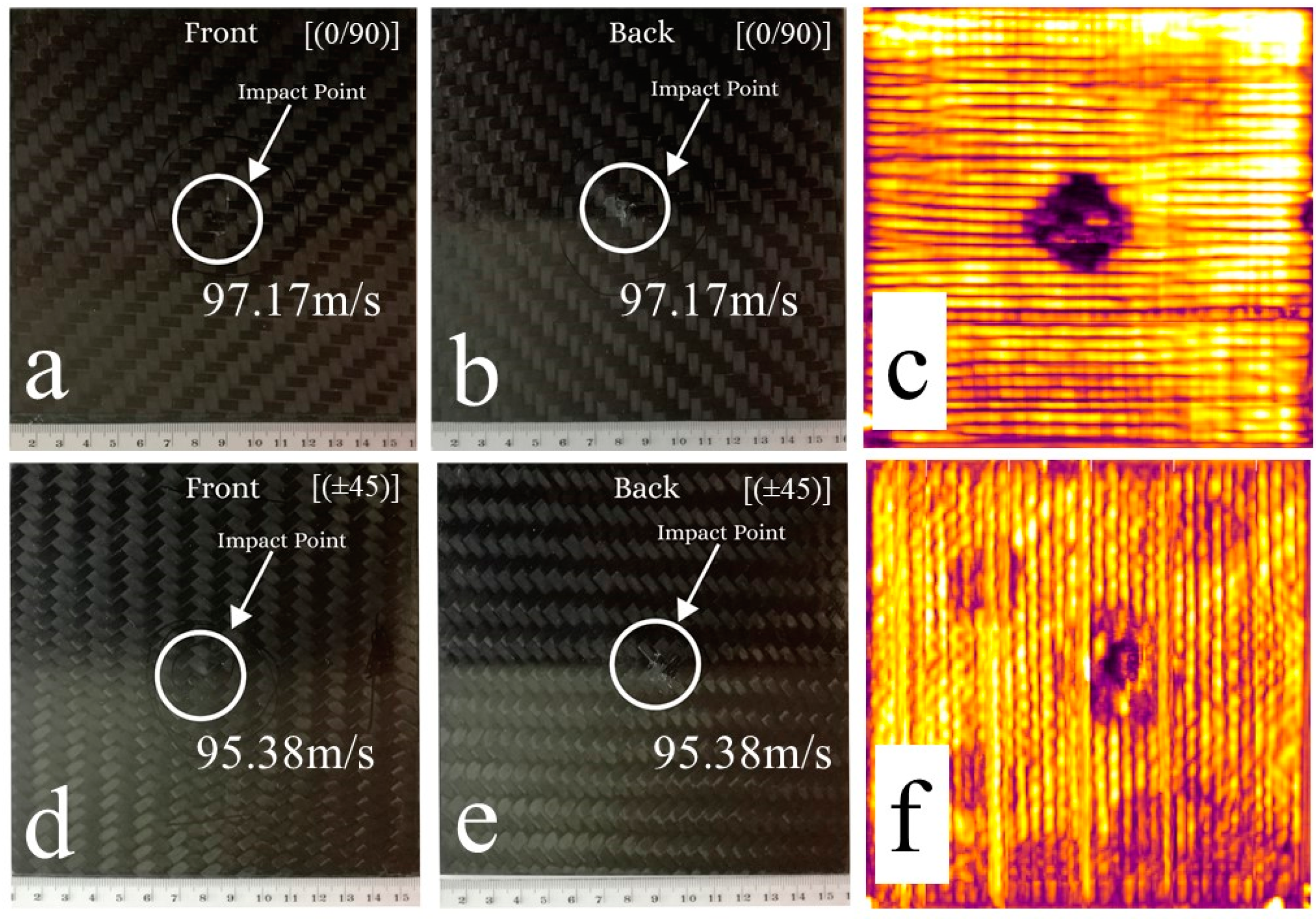
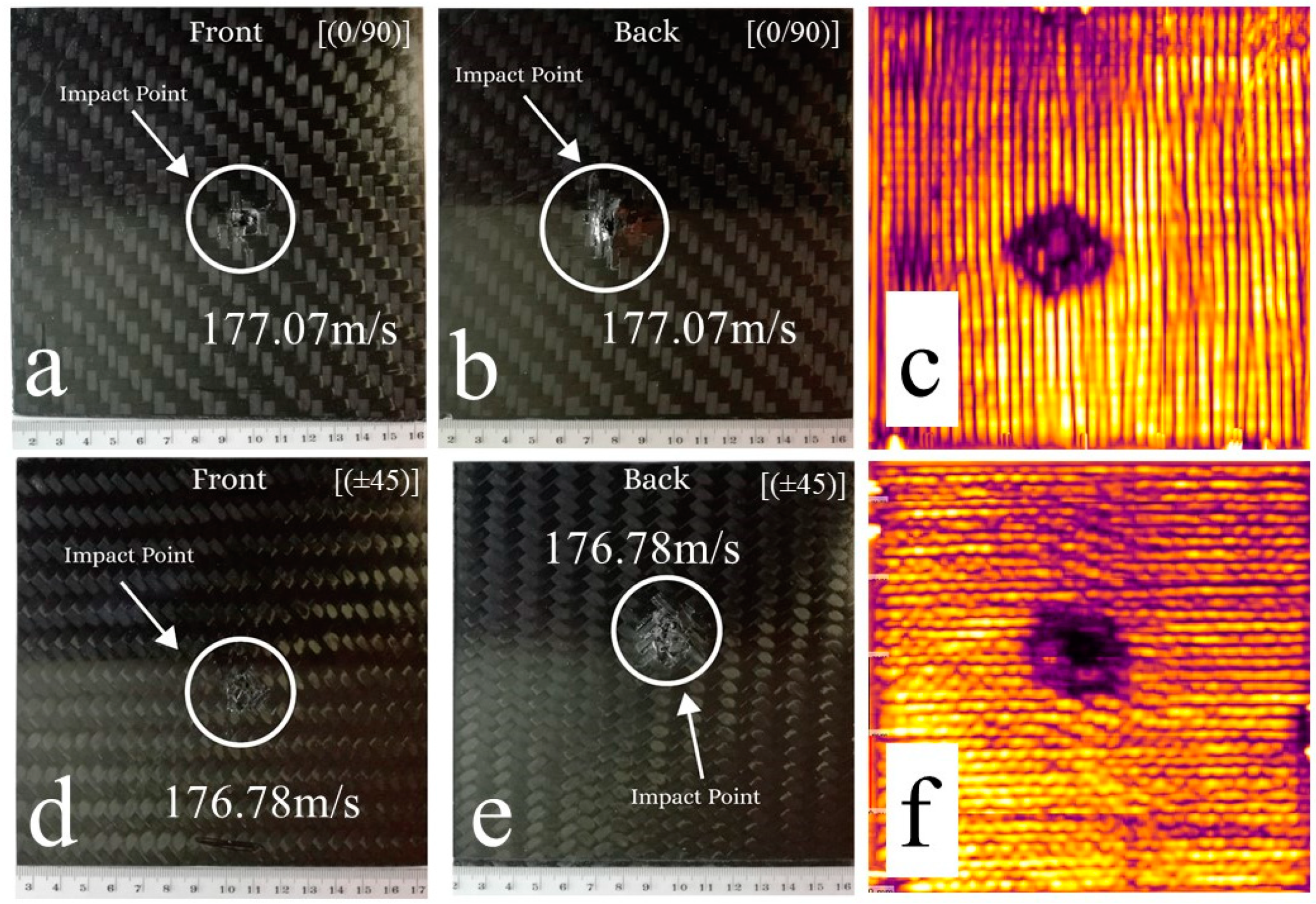
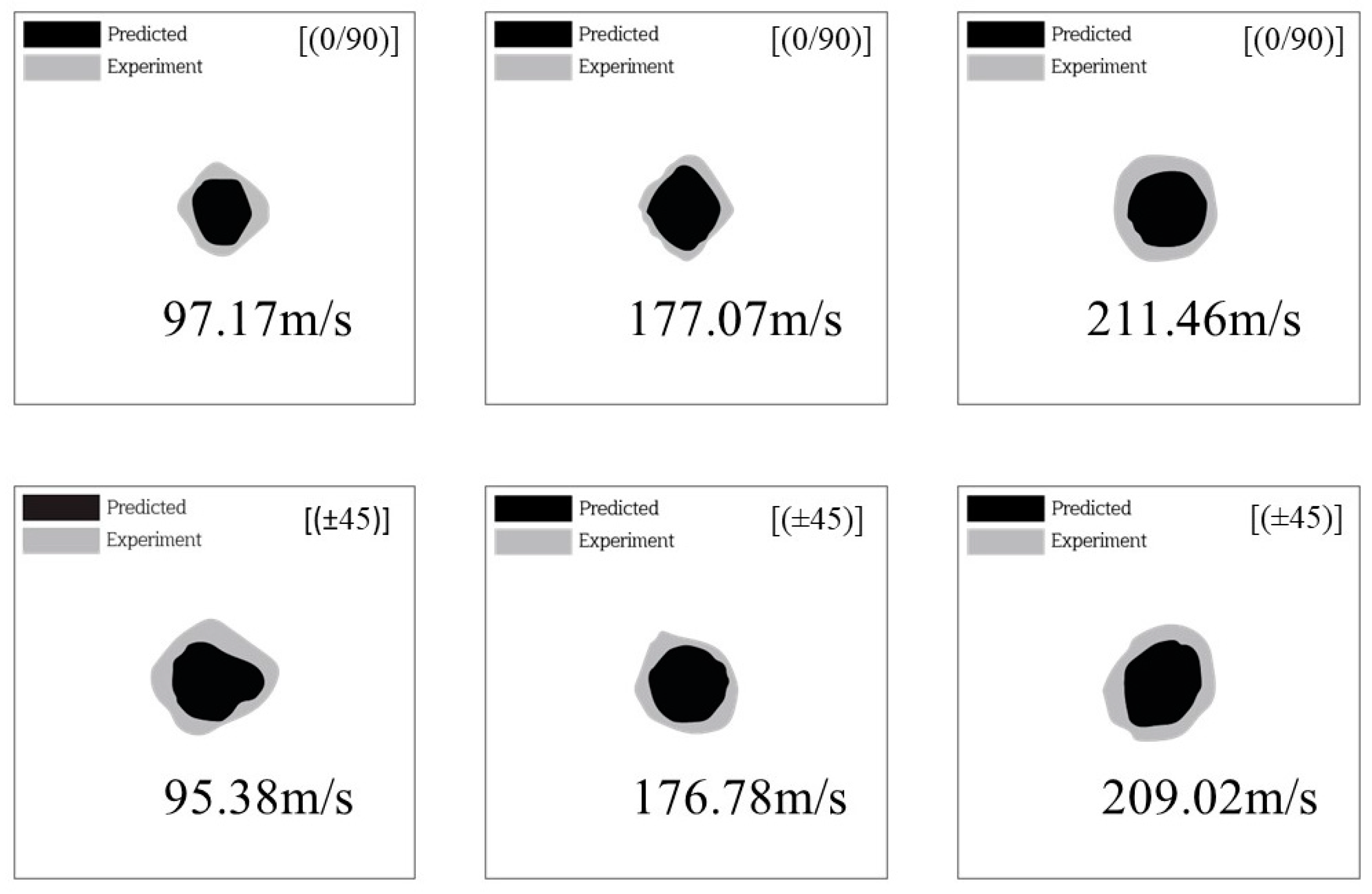
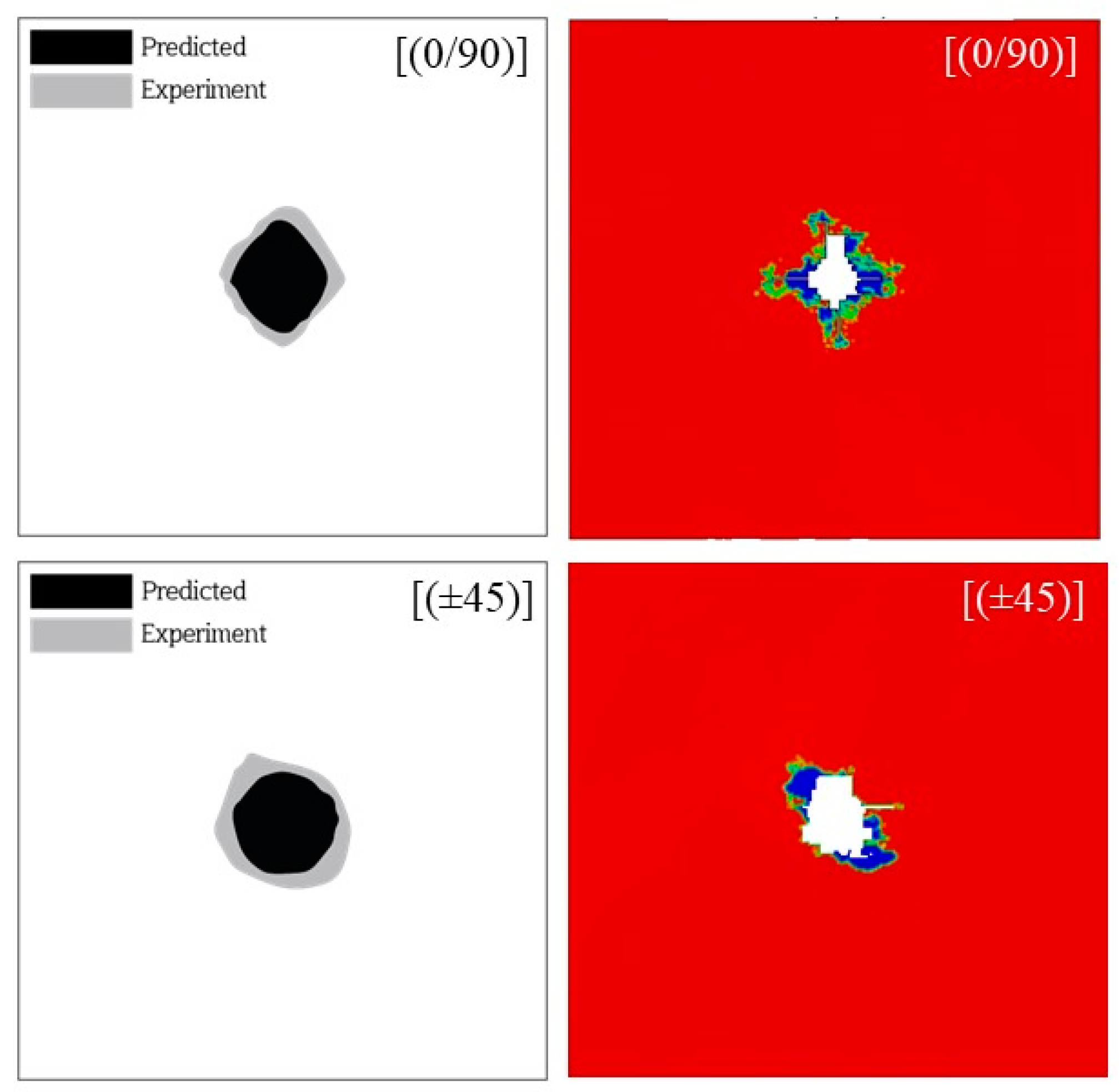
In this work, we evaluated the damage prediction capability of two numerical modelling strategies, for ballistic impact of foreign objects onto composite woven CFRP targets. Initially, a number of experiments were performed that would later serve as benchmark studies for the numerical model results.
In terms of the experimental boundary conditions used in the study, the plates were attached onto an upper and a lower beam inside the impact chamber as shown in
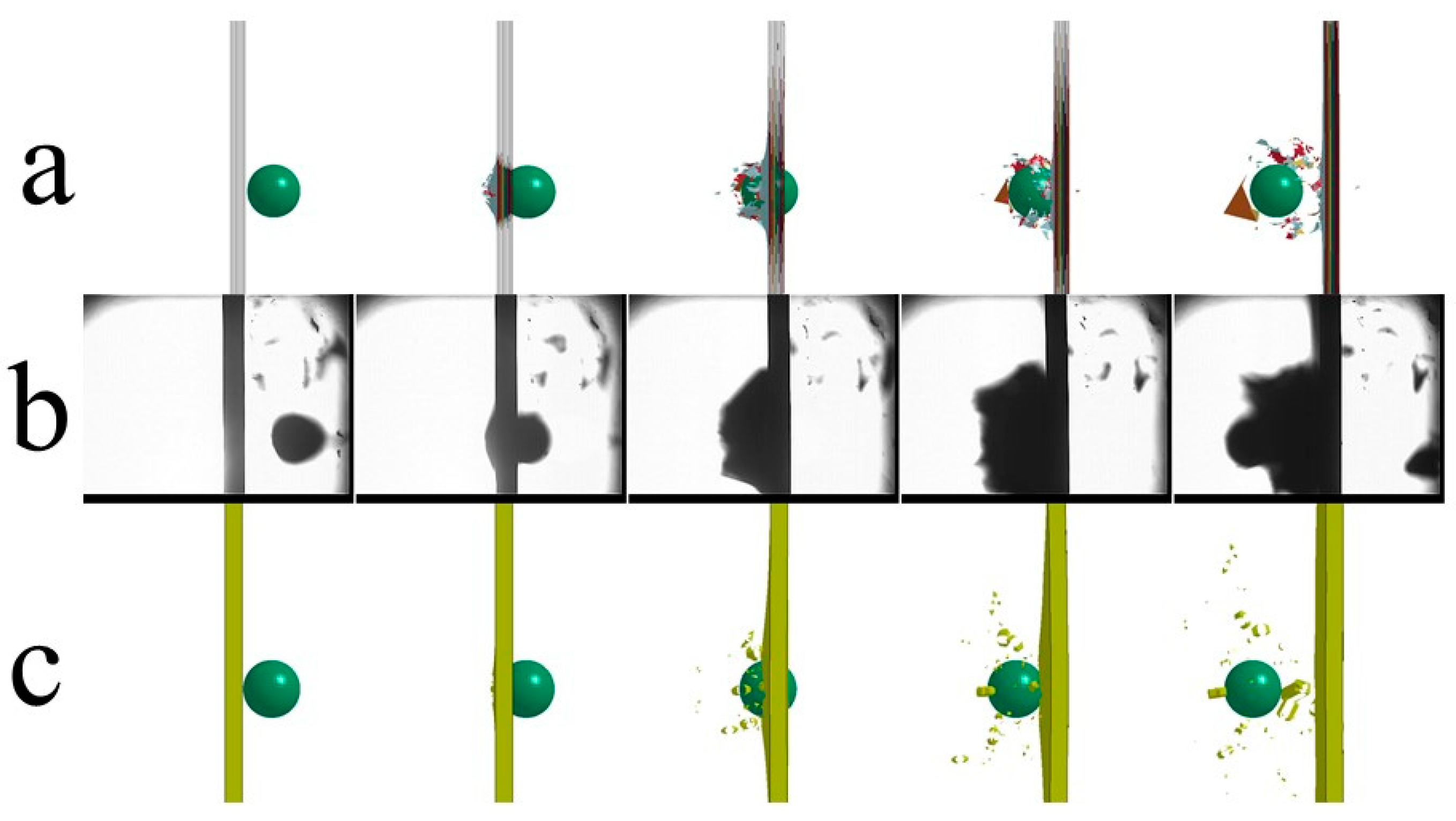
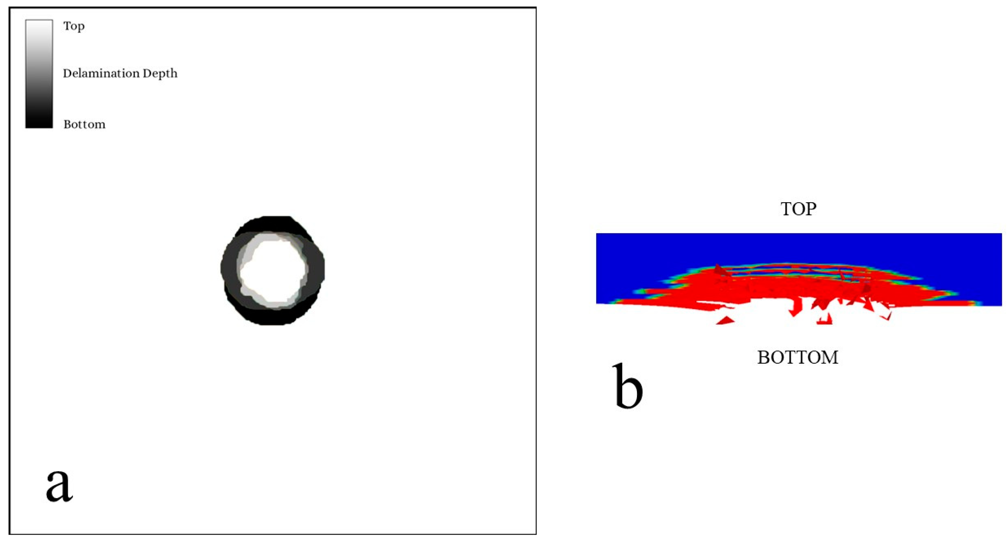
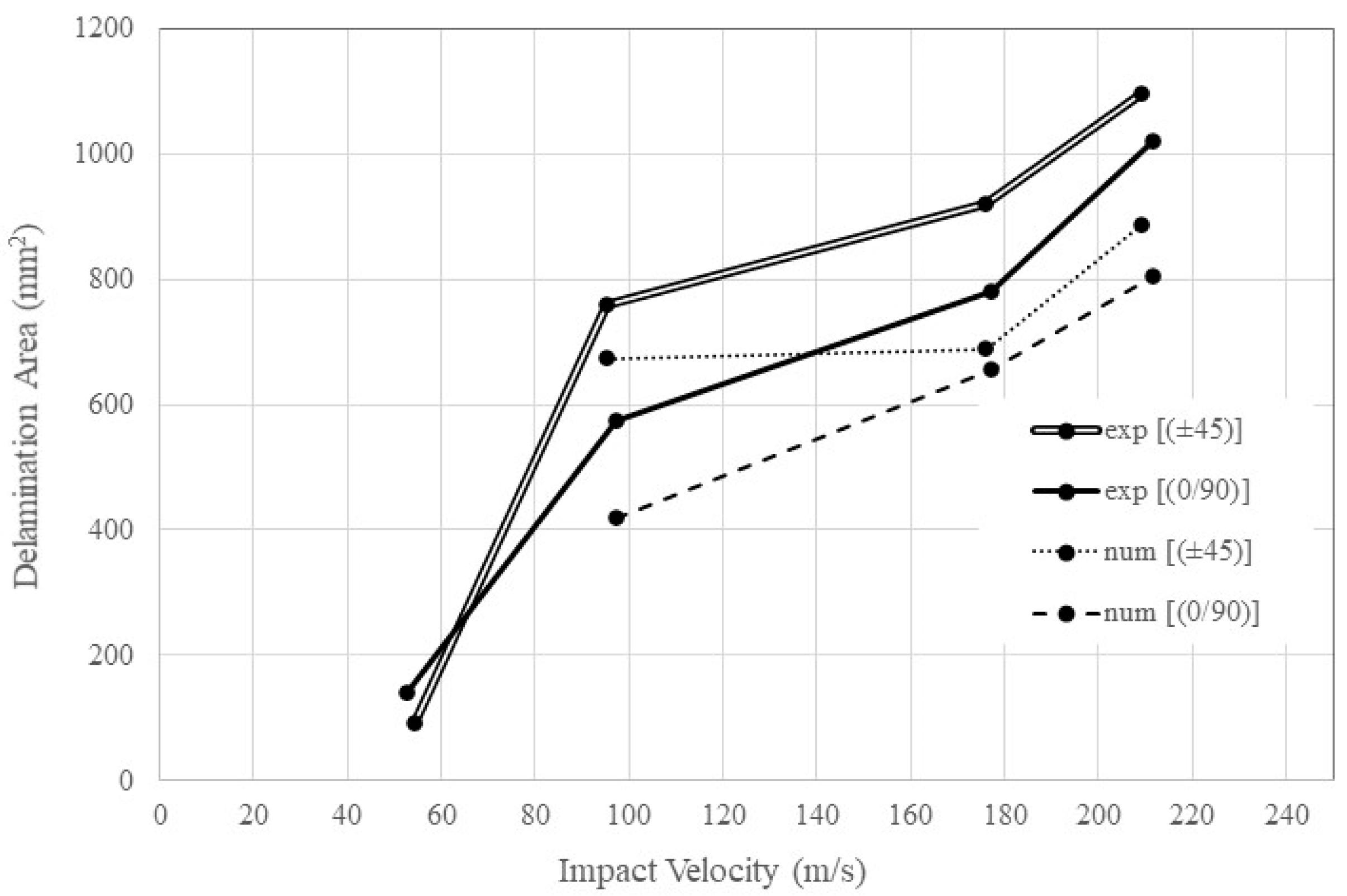
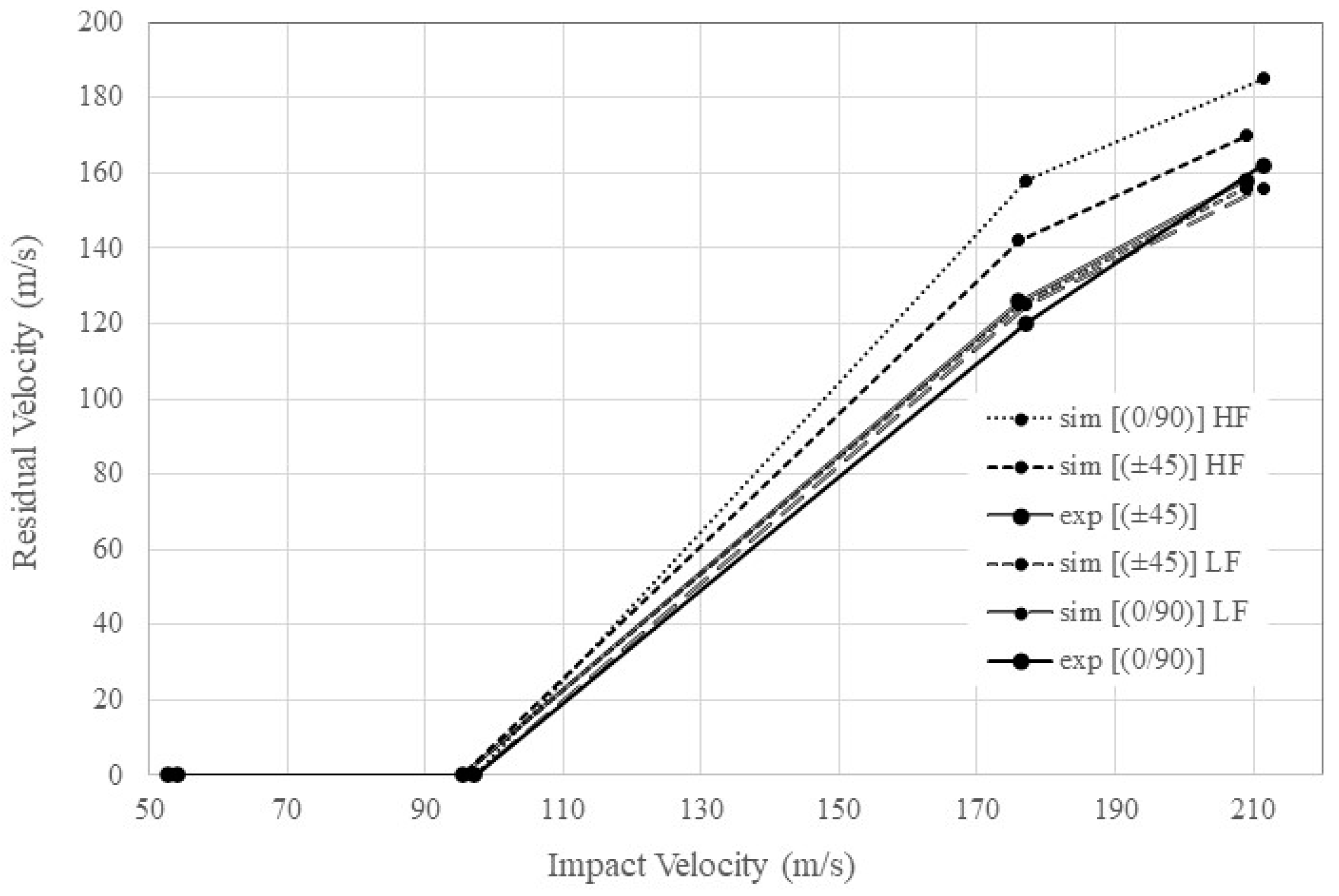
Figure 2b. Such boundary conditions were not of the ordinary square frame type most often used. This attachment is expected to have affected the damage extend results and the overall laminate behaviour, since in the [(0/90)] for example, more layers were attached along the fibre direction onto the boundaries rather than in the case of the [(±45)] having inclined layers. For high-speed impacts though, the impact response is largely governed by the material behaviour close to the impact location. It is expected for the two laminate configurations to perform slightly differently in terms of the damage extends size if using different boundary conditions, as in the case of a square frame attachment for example. It is even expected for the [(±45)] to exhibit a better overall performance against damage accumulation. Although the [(0/90)] configuration performed better in this study, the focus was to evaluate the behaviour of the numerical models. The HF models completed on average in 4.2 h on regular desktop PC whereas LF models completed on average in 0.8 h. In terms of the numerical simulations, the HF model was able to capture inter as well as intra laminar damage at the expense of about 80% higher computational cost with respect to the LF one. The LF model was able to capture just the intra laminar damage, whilst it predicted the residual exit velocity of the projectile more precisely than the HF model. The HF model was numerically simulated and delaminations were found to be smaller from the experimentally measured ones. This deviation may be attributed to the fracture toughness values used and shown in
Table 4, and was derived for similar fabrics but not the exact same one used herein. Although simulations took place to match the reported values with benchmark virtual tests, it is highly likely for the fracture toughness values of the specimens used in this study to be different. For ballistic type of impacts with significant higher energies than those in low velocity impacts, the major energy dissipation mechanisms can be attributed to fibre failure. The HF modelled inter-laminar delamination are not considered one of the major energy absorption mechanisms so the deviation in inter-laminar fracture toughness is not expected to have significant effect on the overall process. It is expected that the higher the energies involved during the impact, the lower the significance in the deviation of the inter-laminar fracture toughness in terms of damage energy absorption. This was evidenced during the HF and LF simulations, the LF model captured the overall energy absorption through the residual velocity in a much better way than the HF model. Of course, delamination modelling can be important if the damage extents need to be quantified for evaluating the plate residual strength, but it was evident that it did not contribute much to the overall impact energy absorption. An alternative model could be suggested as one that would contain a fewer number of inter laminar boundaries modelled, preferably close to the bottom of the plate, for capturing the damage extends. That would increase the damage detail extracted from a LF model, keeping in the same time the computational cost at a reasonable rate.


