
Influence of a Dynamic Consolidation Force on In Situ Consolidation Quality of Thermoplastic Composite Laminate


Abstract
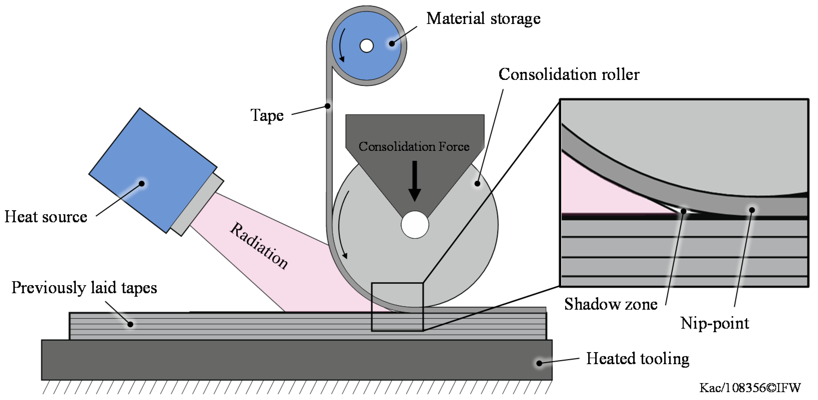
1. Introduction
2. Materials and Methods
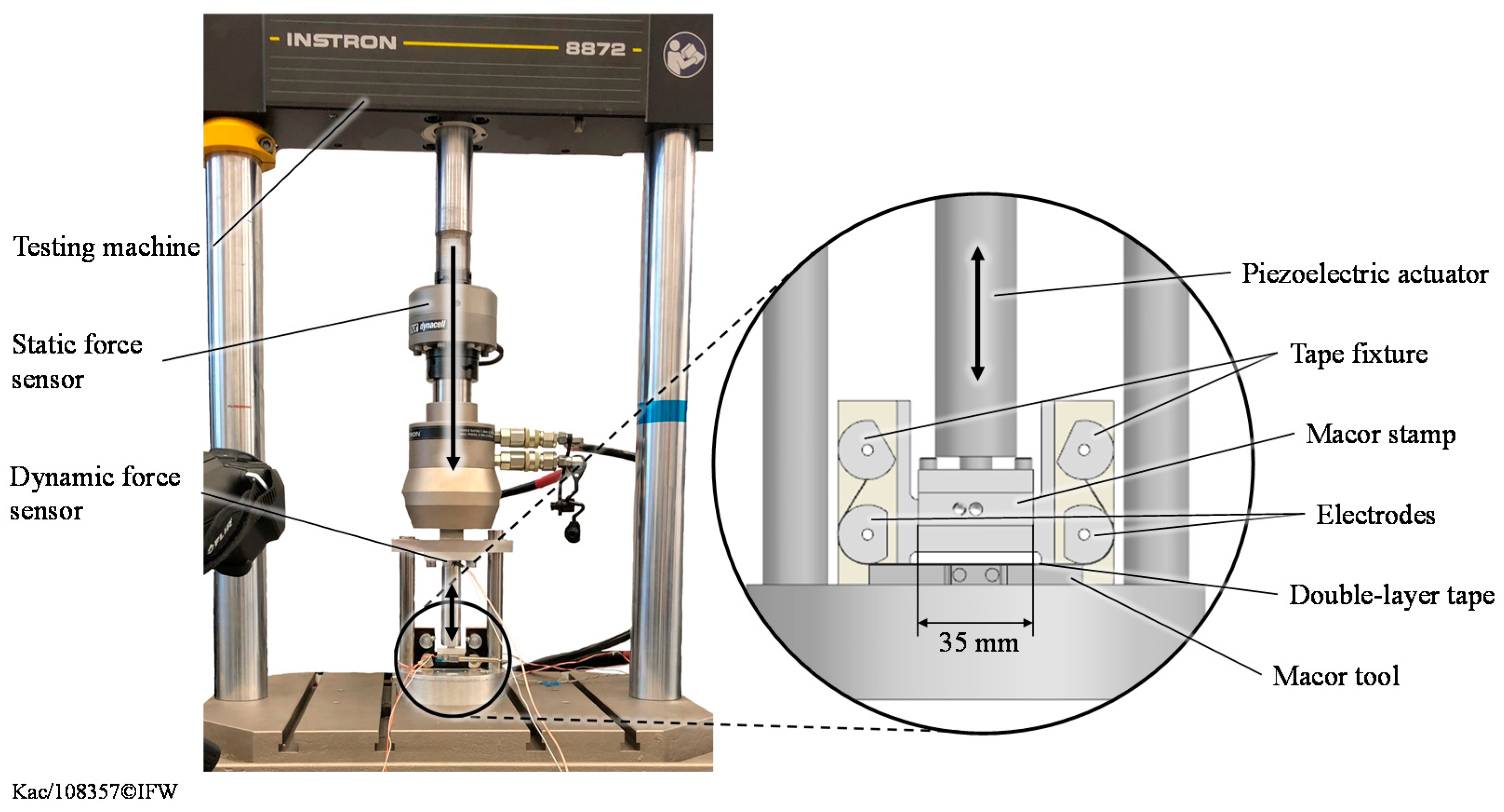
2.1. Experimental Setup
2.2. Material
2.3. Specimen Manufacturing
2.4. Consolidation Quality Evaluation
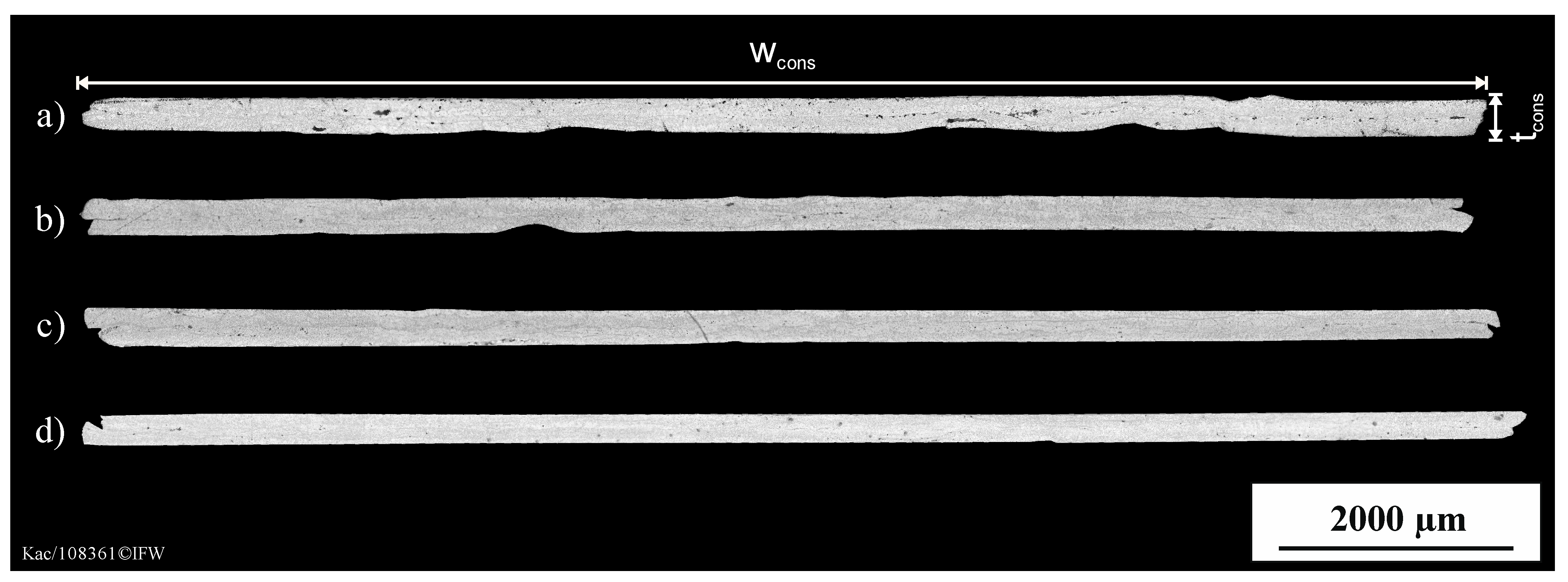
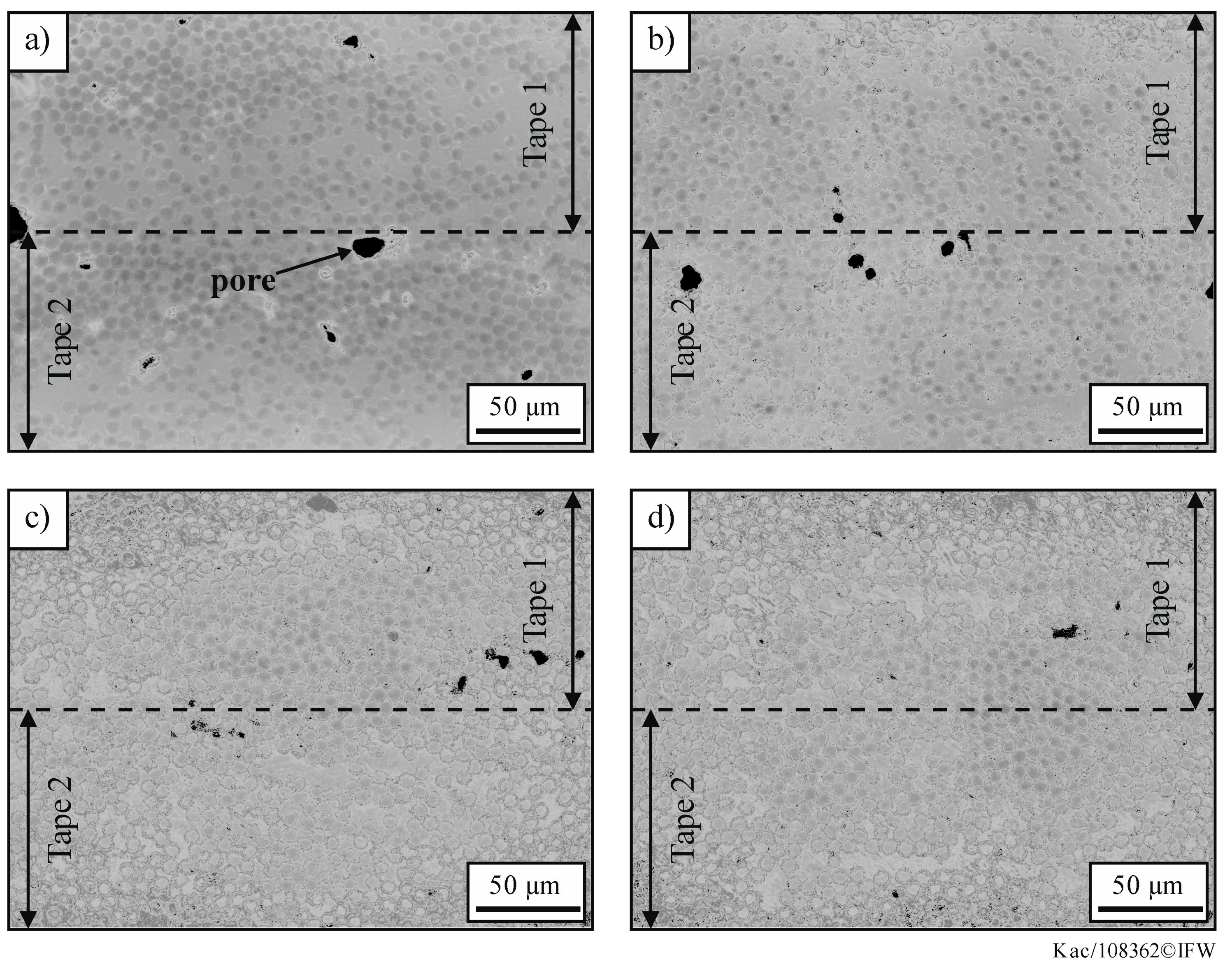
2.4.1. Laser Scanning Microscopy
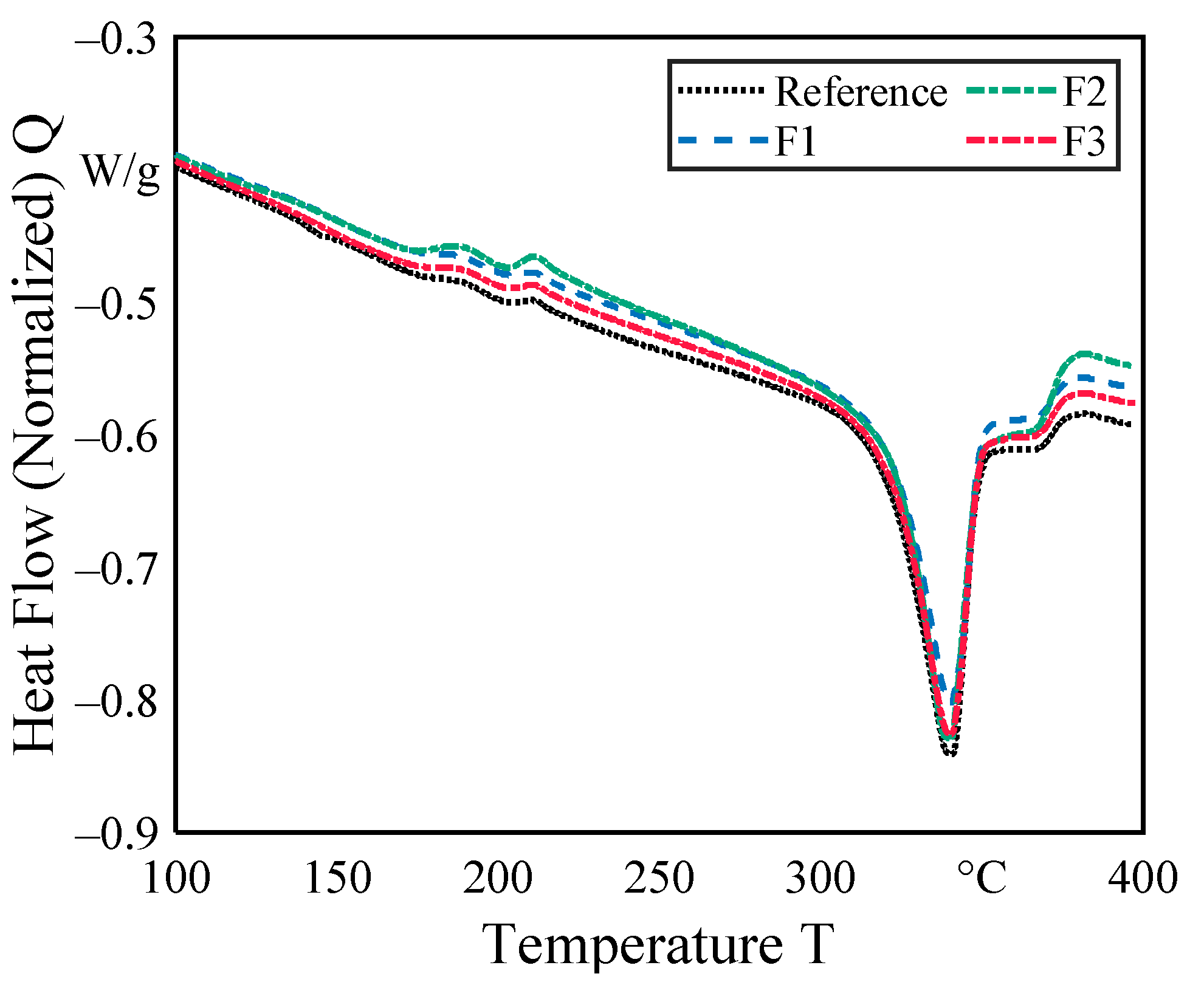
2.4.2. Differential Scanning Calorimetry (DSC)
3. Results
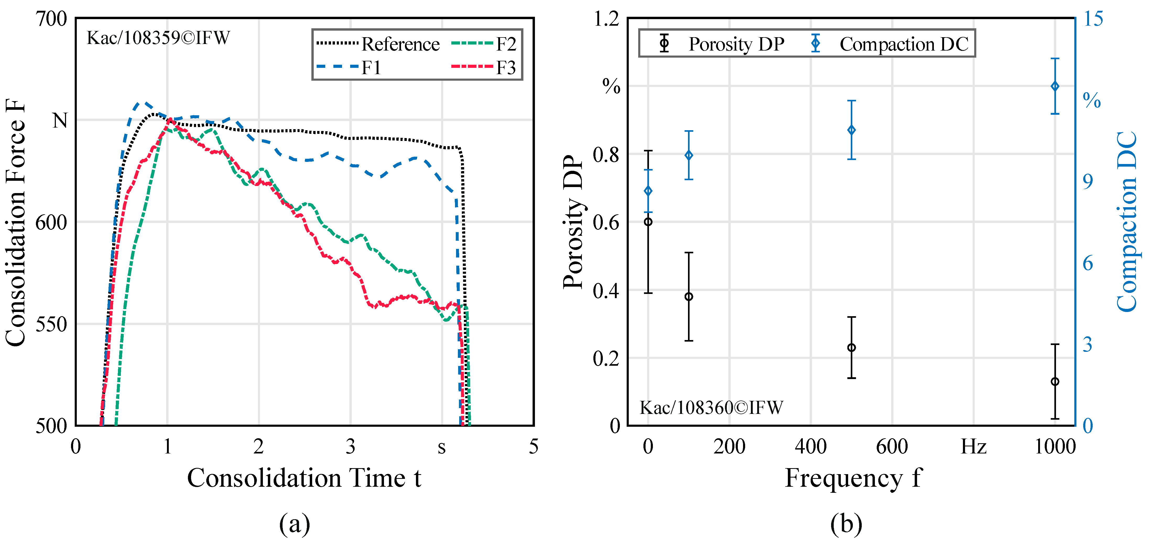
3.1. Consolidation Force
3.2. Interlaminar Porosity and Compaction
3.3. Degree of Crystallization
4. Discussion and Conclusions
- The static consolidation force has a higher decreasing rate for higher frequencies which leads to the conclusion that the relaxation capacity of the viscoelastic PEEK material increases. This is due to a decrease in viscosity, which is beneficial for the development of intimate contact. However, for use in AFP systems a fast pressure control system has to be implemented to control the reduced pressure according to the lay-up velocity.
- Considering the consolidation force results, it was found that the interlaminar pore content can be reduced in the consolidation of PEEK/CF tapes by applying high frequencies (>500 Hz) during the consolidation process. A positive consequence is a higher degree of intimate contact. Due to the high consolidation time the absolute values of porosity are very low and thus not representative for TAFP processes.
- The degree of compaction increases with increasing frequency. An increase in width and a decrease in thickness can be seen here.
Author Contributions
Funding
Data Availability Statement
Conflicts of Interest
References
- Schledjewski, R. Thermoplastic tape placement process—In situ consolidation is reachable. Plast. Rubber Compos. 2009, 38, 379–386. [Google Scholar] [CrossRef]
- Stokes-Griffin, C.M.; Matuszyk, T.I.; Compston, P.; Cardew-Hall, M.J. Modelling the Automated Tape Placement of Thermoplastic Composites with In-Situ Consolidation. In Sustainable Automotive Technologies, Proceedings of the 4th International Conference, Melbourne, Australia; Subic, Wellnitz, Leary, Koopmans; Springer: Heidelberg, Germany, 2012. [Google Scholar] [CrossRef]
- Dara, P.H.; Loos, A.C. Thermoplastic Matrix Composite Processing Model; Virginia Polytecnic Institut: Blacksburg, VA, USA, 1985. [Google Scholar]
- Stokes-Griffin, C.M.; Compston, P.; Matuszyk, T.I.; Cardew-Hall, M.J. Thermal modelling of the laser-assisted thermoplastic tape placement process. J. Thermoplast. Compos. Mater. 2015, 28, 1445–1462. [Google Scholar] [CrossRef]
- Sarrazin, H.; Springer, G.S. Thermochemical and mechanical aspects of composite tape laying. J. Compos. Mater. 1995, 29, 1908–1943. [Google Scholar] [CrossRef]
- Maurer, D.; Mitschang, P. Laser-powered tape placement process-simulation and optimization. Adv. Manuf. Polym. Compos. Sci. 2015, 1, 129–137. [Google Scholar] [CrossRef]
- Comer, A.J.; Ray, D.; Obande, W.O.; Jones, D.; Lyons, J.; Rosca, I.; O’Higgins, R.M.; McCarthy, M.A. Mechanical characterization of carbon fibre-PEEK manufactured by laser-assisted automated-tape-placement and autoclave. Compos. Part A Appl. Sci. Manuf. 2015, 69, 10–20. [Google Scholar] [CrossRef]
- Grouve, W.J.B.; Warnet, L.L.; Rietmann, B.; Akkerman, R. On the weld strength of in situ tape placed reinforcements on weave reinforced structures. Compos. Part A Appl. Sci. Manuf. 2012, 43, 1530–1536. [Google Scholar] [CrossRef]
- Lee, W.I.; Springer, G.S. A Model of the Manufacturing Process of Thermoplastic Matrix Composites. J. Compos. Mater. 1987, 21, 1017–1055. [Google Scholar] [CrossRef]
- Pitchumani, R.; Ranganathan, S.; Don, R.C.; Gillespie, J.W.; Lamontia, M.A. Analysis of transport phenomena governing interfacial bonding and void dynamics during thermoplastic tow-placement. Int. J. Heat Mass. Transf. 1996, 39, 1883–1897. [Google Scholar] [CrossRef]
- Pitchumani, R.; Gillespie, J.W.; Lamontia, M.A. Design and Optimization of a Thermoplastic Tow-Placement Process with in-situ Consolidation. J. Compos. Mater. 1997, 31, 244–275. [Google Scholar] [CrossRef]
- Yang, F.; Pitchumani, R. A fractal Cantor set based description of interlaminar contact evolution during thermoplastic composites processing. J. Mater. Sci. 2001, 36, 4461–4671. [Google Scholar] [CrossRef]
- Yang, F.; Pitchumani, R. Nonisothermal Healing and Interlaminar Bond Strength Evolution During Thermoplastic Matrix Composites Processing. Polym. Compos. 2003, 24, 263–278. [Google Scholar] [CrossRef]
- Khan, M.A.; Mitschang, P.; Schledjewski, R. Identification of some optimal parameters to achieve higher laminate quality through tape placement process. Adv. Polym. Technol. 2010, 29, 98–111. [Google Scholar] [CrossRef]
- Celik, O.; Peeters, D.; Dransfeld, C.; Teuwen, J. Intimate contact development during laser assisted fiber placement: Microstructure and effect of process parameters. Compos. Part A Appl. Sci. Manuf. 2020, 134. [Google Scholar] [CrossRef]
- Oromiehie, E.; Garbe, U.; Prusty, B.G. Porosity analysis of carbon fibre-reinforced polymer laminates manufactured using automated fibre placement. J. Compos. Mater. 2020, 54, 1217–1231. [Google Scholar] [CrossRef]
- Leon, A.; Argerich, C.; Barasinski, A.; Soccard, E.; Chinesta, F. Effects of material and process parameters on in-situ consolidation. Int. J. Mater. Form. 2019, 12, 491–503. [Google Scholar] [CrossRef]
- Stokes-Griffin, C.M.; Compston, P. Investigation of sub-melt temperature bonding of carbon-fibre/PEEK in an automated laser tape placement process. Compos. Part A Appl. Sci. Manuf. 2016, 84, 17–25. [Google Scholar] [CrossRef]
- Stokes-Griffin, C.M.; Compston, P. An inverse model for optimization of laser heat flux distributions in an automated laser tape placement process for carbon-fibre/PEEK. Compos. Part A Appl. Sci. Manuf. 2016, 88, 190–197. [Google Scholar] [CrossRef]
- Schaefer, P.M.; Guglhoer, T.; Sause, M.G.R.; Drechsler, K. Development of intimate contact during processing of carbon fiber reinforced Polyamide-6 tapes. J. Reinf. Plast. Compos. 2017, 36, 593–607. [Google Scholar] [CrossRef]
- Celik, O.; Teuwen, J. Effects of Process Parameters on Intimate Contact Development in Laser Assisted Fiber Placement. In Proceedings of the 4th Automated Composites Manufacturing (ACM4), Montreal, QC, Canada, 25–26 April 2019. [Google Scholar]
- Levy, A.; Heider, D.; Tierney, J.; Gillespie, J.W. Inter-layer thermal contact resistance evolution with the degree of intimate contact in the processing of thermoplastic composite laminates. J. Compos. Mater. 2014, 48, 491–503. [Google Scholar] [CrossRef]
- Stokes-Griffin, C.M.; Compston, P.; Stokes-Griffin, C.M.; Compston, P. A combined optical-thermal model for near-infrared laser heating of thermoplastic composites in an automated tape placement process. Compos. Part A Appl. Sci. Manuf. 2015, 75, 104–115. [Google Scholar] [CrossRef]
- Stokes-Griffin, C.M.; Compston, P. The effect of processing temperature and placement rate on the short beam strength of carbon fibre–PEEK manufactured using a laser tape placement process. Compos. Part A Appl. Sci. Manuf. 2015, 78, 274–283. [Google Scholar] [CrossRef]
- Barasinski, A.; Leygue, A.; Soccard, E.; Poitou, A. In situ consolidation for thermoplastic tape placement process is not obvious. AIP Conf. Proc. 2011, 1353, 948. [Google Scholar] [CrossRef]
- Kok, T.; Grouve, W.J.B.; Warnet, L.L.; Akkerman, R. Intimate contact development in laser assisted fiber placement. In Proceedings of the ECCM17—17th European Conference on Composite Materials, Munich, Germany, 26–30 June 2016; Drechsler. ESCM European Society for Composite Materials: Munich, Germany, 2016. [Google Scholar]
- Sonmez, F.O.; Akbulut, M. Process optimization of tape placement for thermoplastic composites. Compos. Part A Appl. Sci. Manuf. 2007, 38, 2013–2023. [Google Scholar] [CrossRef]
- Kollmansberger, A. Heating Characteristics of Fixed Focus Laser Assisted Thermoplastic-Automated Fiber Placement of 2D and 3D Parts. Ph.D. Thesis, Technical University Munich, Munich, Germany, 2019. [Google Scholar]
- Brzeski, M. Experimental and Analytical Investigation of Deconsolidation for Fiber Reinforced Thermoplastic Composites. Ph.D. Thesis, Technical University Kaiserslautern, Kaiserslautern, Germany, 2014. [Google Scholar]
- Lionetto, F.; Dell’Anna, R.; Montagna, F.; Maffezzoli, A. Modeling of continuous ultrasonic impregnation and consolidation of thermoplastic matrix composites. Compos. Part A Appl. Sci. Manuf. 2016, 82, 119–129. [Google Scholar] [CrossRef]
- Rizzolo, R.H.; Walczyk, D.F. Ultrasonic consolidation of thermoplastic composite prepreg for automated fiber placement. J. Thermoplast. Compos. Mater. 2016, 29, 1480–1497. [Google Scholar] [CrossRef]
- Chu, Q.; Li, Y.; Xiao, J.; Huan, D.; Zhang, X.; Chen, X. Processing and characterization of the thermoplastic composites manufactured by ultrasonic vibration-assisted automated fiber placement. J. Thermoplast. Compos. Mater. 2018, 31, 339–358. [Google Scholar] [CrossRef]
- Tolunay, M.N.; Dawson, P.R. Heating and Bonding Mechanisms in Ultrasonic Welding of Thermoplastics. Polym. Eng. Sci. 1983, 23, 726–733. [Google Scholar] [CrossRef]
- Benatar, A.; Gutowski, T.G. Ultrasonic Welding of PEEK Graphite APC-2 Composites. Polym. Eng. Sci. 1989, 29, 1705–1721. [Google Scholar] [CrossRef]
- Levy, A.; Le Corre, S.; Villegas, I.F. Modeling of the heating phenomena in ultrasonic welding of thermoplastic composites with flat energy directors. J. Mater. Process. Technol. 2014, 214, 1361–1371. [Google Scholar] [CrossRef]
- Jeng, C.; Chen, M. Flexural failure mechanisms in injection-moulded carbon fibre/PEEK composites. Compos. Sci. Technol. 2000, 60, 1863–1872. [Google Scholar] [CrossRef]
- Mantell, S.C.; Springer, G.S. Manufacturing Process Models for Thermoplastic Composites. J. Compos. Mater. 1992, 29, 2348–2377. [Google Scholar] [CrossRef]
- Khan, M.A.; Mitschang, P.; Schledjewski, R. Parametric study on processing parameters and resulting part quality through thermoplastic tape placement process. J. Compos. Mater. 2013, 47, 485–499. [Google Scholar] [CrossRef]
- Di Francesco, M.; Giddings, P.F.; Scott, M.; Goodman, E.; Dell’Anno, G. Influence of laser power density on the meso-structure of thermoplastic composite preforms manufactured by automated fibre placement. In International SAMPE Technical Conference, Proceedings of the SAMPE Long Beach 2016 Conference and Exhibition, Long Beach, CA, USA, 23–26 May 2016; Society for the Advancement of Material and Process Engineering: Diamond Bar, CA, USA, 2016. [Google Scholar]
- Saenz-Castillo, D.; Martin, M.I.; Garcia-Martinez, V.; Ramesh, A.; Battley, M.; Güemes, A. A comparison of mechanical properties and X-ray tomography analysis of different out-of-autoclave manufactured thermoplastic composites. J. Reinf. Plast. Compos. 2020, 39, 703–720. [Google Scholar] [CrossRef]


| Specimen | Temperature °C | Static Force N | Amplitude µm | Frequency Hz | Time s |
|---|---|---|---|---|---|
| Reference | 380 | 650 | 10 | 0 | 3 |
| F1 | 380 | 650 | 10 | 100 | 3 |
| F2 | 380 | 650 | 10 | 500 | 3 |
| F3 | 380 | 650 | 10 | 1000 | 3 |
| Specimen | Thickness µm | Width µm | CSA µm2 | Compaction % | Porosity % |
|---|---|---|---|---|---|
| Reference | 286 ± 1.91 | 11,754 ± 130 | 3,362,090 ± 28,536 | 8.64 ± 0.78 | 0.60 ± 0.21 |
| F1 | 284 ± 2.96 | 11,655 ± 60 | 3,314,010 ± 32,631 | 9.95 ± 0.89 | 0.38 ± 0.13 |
| F2 | 276 ± 4.13 | 11,785 ± 113 | 3,279,507 ± 39,776 | 10.88 ± 1.08 | 0.23 ± 0.09 |
| F3 | 268 ± 4.28 | 12,007 ± 117 | 3,220,322 ± 37,621 | 12.49 ± 1.02 | 0.13 ± 0.11 |
Publisher’s Note: MDPI stays neutral with regard to jurisdictional claims in published maps and institutional affiliations. |
© 2021 by the authors. Licensee MDPI, Basel, Switzerland. This article is an open access article distributed under the terms and conditions of the Creative Commons Attribution (CC BY) license (http://creativecommons.org/licenses/by/4.0/).
Share and Cite
Denkena, B.; Schmidt, C.; Kaczemirzk, M.; Schwinn, M. Influence of a Dynamic Consolidation Force on In Situ Consolidation Quality of Thermoplastic Composite Laminate. J. Compos. Sci. 2021, 5, 88. https://doi.org/10.3390/jcs5030088
Denkena B, Schmidt C, Kaczemirzk M, Schwinn M. Influence of a Dynamic Consolidation Force on In Situ Consolidation Quality of Thermoplastic Composite Laminate. Journal of Composites Science. 2021; 5(3):88. https://doi.org/10.3390/jcs5030088
Chicago/Turabian StyleDenkena, Berend, Carsten Schmidt, Maximilian Kaczemirzk, and Max Schwinn. 2021. "Influence of a Dynamic Consolidation Force on In Situ Consolidation Quality of Thermoplastic Composite Laminate" Journal of Composites Science 5, no. 3: 88. https://doi.org/10.3390/jcs5030088
APA StyleDenkena, B., Schmidt, C., Kaczemirzk, M., & Schwinn, M. (2021). Influence of a Dynamic Consolidation Force on In Situ Consolidation Quality of Thermoplastic Composite Laminate. Journal of Composites Science, 5(3), 88. https://doi.org/10.3390/jcs5030088