Designing Hierarchical Honeycombs to Mimic the Mechanical Behaviour of Composites


Abstract
1. Introduction
2. Materials and Methods
3. Results
3.1. Tensile Properties of TRPC, SHRPC and CFRP
3.2. Comparison of TRPC and SHRPC Mechanical Properties
4. Discussion
5. Conclusions
Author Contributions
Funding
Institutional Review Board Statement
Informed Consent Statement
Data Availability Statement
Conflicts of Interest
References
- Bertoldi, K.; Vitelli, V.; Christensen, J.; van Hecke, M. Flexible mechanical metamaterials. Nat. Rev. 2017, 2, 1–11. [Google Scholar]
- Yu, X.; Zhou, J.; Liang, H.; Jiang, A.; Wu, L. Mechanical metamaterials associated with stiffness, rigidity and compressibility: A brief review. Prog. Mater. Sci. 2018, 94, 114–173. [Google Scholar] [CrossRef]
- Zheludev, N.I. The road ahead for metamaterials. Science 2010, 328, 582–583. [Google Scholar] [CrossRef] [PubMed]
- Christensen, J.; Kadic, M.; Kraft, O.; Wegener, M. Vibrant times for mechanical meta-materials. MRS Commun. 2015, 5, 453–462. [Google Scholar] [CrossRef]
- Evans, K.E.; Alderson, A. Auxetic materials: Functional materials and structures from lateral thinking. Adv. Mater. 2000, 12, 617–628. [Google Scholar] [CrossRef]
- Gatt, R.; Grima, J.N. Negative compressibility. Physica Status Solidi (RRL) 2008, 2, 236–238. [Google Scholar] [CrossRef]
- Nicolaou, Z.G.; Motter, A.E. Mechanical metamaterials with negative compressibility transitions. Nat. Mater. 2012, 11, 608–613. [Google Scholar] [CrossRef]
- Kadic, M.; Buckmann, T.; Stenger, N.; Thiel, M.; Wegener, M. On the practicability of pentamode mechanical metamaterials. Appl. Phys. Lett. 2012, 100, 191901. [Google Scholar] [CrossRef]
- Wyart, M.; Liang, H.; Kabla, A.; Mahadevan, L. Elasticity of floppy and stiff random networks. Phys. Rev. Lett. 2008, 101, 215501. [Google Scholar] [CrossRef]
- Paulose, J.; Chen, B.G.; Vitelli, V. Topological modes bound to dislocations in mechanical metamaterials. Nat. Phys. 2015, 11, 153–156. [Google Scholar] [CrossRef]
- Davami, K.; Zhao, L.; Lu, E.; Cortes, J.; Lin, C.; Lilley, D.E.; Purohit, P.K.; Bargatin, I. Ultralight shape-recovering plate mechanical metamaterials. Nat. Commun. 2015, 6, 1–7. [Google Scholar] [CrossRef] [PubMed]
- Malek, S.; Raney, J.R.; Lewis, J.A.; Gibson, L.J. Lightweight 3D cellular composites inspired by balsa. Bioinsp. Biomim. 2017, 12, 026014. [Google Scholar] [CrossRef] [PubMed]
- Avalle, M.; Belingardi, G.; Ibba, A. Mechanical models of cellular solids: Parameters identification from experimental tests. Int. J. Impact Eng. 2007, 34, 3–27. [Google Scholar] [CrossRef]
- Taylor, C.M.; Smith, C.W.; Miller, W.; Evans, K. The effects of hierarchy on the in-plane elastic properties of honeycombs. Int. J. Solid Struct. 2011, 48, 1330–1339. [Google Scholar] [CrossRef]
- Gibson, L.J.; Ashby, M.F.; Schajer, G.; Robertson, C. The mechanics of two-dimensional cellular materials. Proc. Royal. Soc. Lond. A 1982, 382, 25–42. [Google Scholar]
- Gibson, L.; Ashby, M.; Zhang, J.; Triantafillou, T. Failure surfaces for cellular materials under multiaxial loads modelling. Int. J. Mech. Sci. 1989, 31, 635–663. [Google Scholar] [CrossRef]
- Wilson, S. A new face of aerospace honeycomb. Mater. Des. 1990, 11, 323–326. [Google Scholar] [CrossRef]
- Zhang, Q.; Yang, X.; Li, P.; Huang, G.; Feng, S.; Shen, C.; Han, B.; Zhang, X.; Jin, F.; Xu, F. Bioinspired engineering of honeycomb structure using nature to inspire human innovation. Prog. Mater. Sci. 2015, 74, 332–400. [Google Scholar] [CrossRef]
- Ajdari, A.; Jahromi, B.H.; Papadopoulos, J.; Nayeb-Hashemi, H.; Vaziri, A. Hierarchical honeycombs with tailorable properties. Int. J. Solid Struct. 2012, 49, 1413–1419. [Google Scholar] [CrossRef]
- Wegst, U.G.; Bai, H.; Saiz, E.; Tomsia, A.P.; Ritchie, R.O. Bioinspired structural materials. Nat. Mater. 2015, 14, 23–36. [Google Scholar] [CrossRef]
- Zhang, D.; Fei, Q.; Liu, J.; Jiang, D.; Li, Y. Crushing of vertex-based hierarchical honeycombs with triangular substructures. Thin-Walled Struct. 2020, 146, 106436. [Google Scholar] [CrossRef]
- He, Q.; Feng, J.; Honggen, Z. A numerical study on the in-plane dynamic crushing of self-similar hierarchical honeycombs. Mech. Mater. 2019, 138, 103151. [Google Scholar] [CrossRef]
- Li, S.; Liu, Z.; Shim, V.P.W.; Guo, Y.; Sun, Z.; Li, X.; Wang, Z. In-plane compression of 3D-printed self-similar hierarchical honeycombs—Static and dynamic analysis. Thin-Walled Struct. 2020, 157, 106990. [Google Scholar] [CrossRef]
- Tao, Y.; Li, W.; Wai, K.; Duan, S.; Wen, W.; Chen, L.; Pei, Y.; Fang, D. Mechanical properties and energy absorption of 3D printed square hierarchical honeycombs under in-plane axial compression. Compos. Part B 2019, 176, 107219. [Google Scholar] [CrossRef]
- Wang, B.; Ding, Q.; Sun, Y.; Yu, S.; Ren, F.; Cao, X.; Du, Y. Enhanced tunable fracture properties of the high stiffness hierarchical honeycombs with stochastic Voronoi substructures. Results Phys. 2020, 12, 1190–1196. [Google Scholar] [CrossRef]
- Ilankeeran, P.K.; Mohite, P.M.; Kamle, S. Axial tensile testing of single fibres. Mod. Mech. Eng. 2012, 2, 151–156. [Google Scholar] [CrossRef]
- Wang, Z.; Liang, Z.; Wang, B.; Zhang, C.; Kramer, L. Processing and property investigation of single-walled carbon nanotube (SWNT) buckypaper/epoxy resin matrix nanocomposites. Compos. Part A 2004, 35, 1225–1232. [Google Scholar] [CrossRef]
- Chung, D.D.L. Carbon Fiber Composites, 1st ed.; Elsevier (Imprint: Butterworth-Heinemann): Oxford, UK, 2012. [Google Scholar]
- Shirasu, K.; Nakamura, A.; Yamamoto, G.; Ogasawara, T.; Shimamura, Y.; Inoue, Y.; Hashida, T. Potential use of CNTS for production of zero thermal expansion coefficient composite materials: An experimental evaluation of axial thermal expansion coefficient of CNTS using a combination of thermal expansion and uniaxial tensile tests. Compos. Part A 2017, 95, 152–160. [Google Scholar] [CrossRef]
- Mouritz, P. Introduction to Aerospace Materials; Elsevier (Imprint: Woodhead Publishing): Cambridge, UK, 2012. [Google Scholar]
- Injeti, S.S.; Daraio, C.; Bhattachrya, K. Metamaterials with engineered failure load and stiffness. Proc. Natl. Acad. Sci. USA 2019, 116, 23960–23965. [Google Scholar] [CrossRef]
- Almadan, Y.; Dirikgil, T. Experimental investigation of the flexural strengthening of fixed-supported RC beams. Int. J. Civil. Eng. 2020, 18, 1229–1246. [Google Scholar] [CrossRef]


| Property | PLA (in TRPC) | PLA (in SHRPC) | Carbon Fibre (in CFRP) | Epoxy Resin (in CFRP) |
|---|---|---|---|---|
| Young’s modulus (GPa) | 3.5 | 3.5 | 246.7 | 2.4 |
| Yield strength (MPa) | 49.5 | 49.5 | 5000 | 35 |
| Poisson’s ratio | 0.33 | 0.33 | 0.26 | 0.35 |
| Density (g/cm3) | 1.24 | 1.24 | 1.8 | 1.3 |
| Young’s Modulus, E, (GPa) | Maximum Strain (%) | Density, ρ, (kg/m3) | E/ρ (MNm/kg) | |
|---|---|---|---|---|
| Pseudo-matrix | 0.052 | 13.9 | 301 | 0.17 |
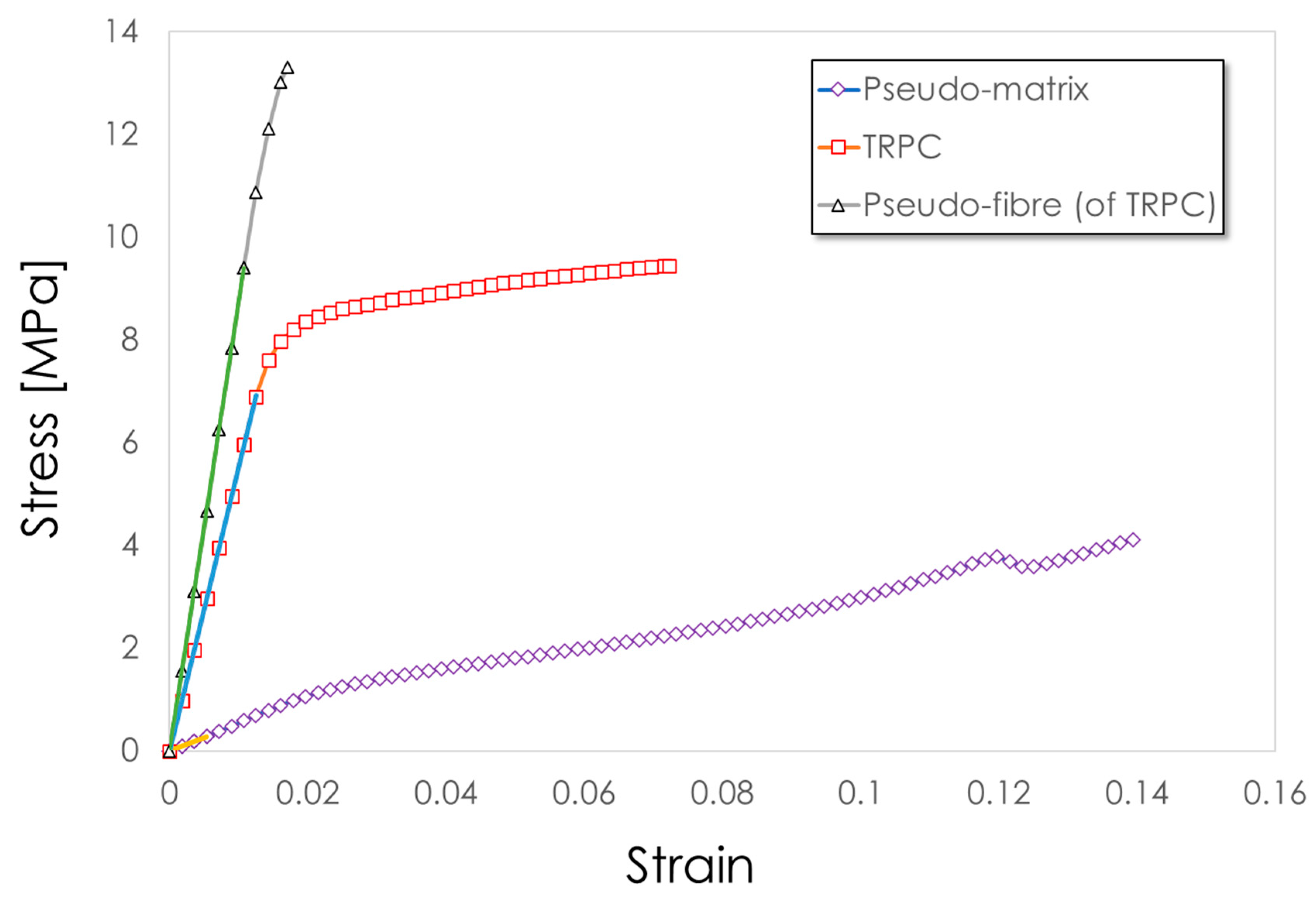
| TRPC | 0.55 | 7.2 | 491 | 1.13 |
| Pseudo-fibre (of TRPC) | 0.87 | 1.7 | 1240 | 0.71 |
| Pseudo-matrix | 0.052 | 13.9 | 301 | 0.17 |
| SHRPC | 0.38 | 10.4 | 491 | 0.77 |
| Pseudo-fibre (of SHRPC) | 0.62 | 5.1 | 1240 | 0.50 |
| Epoxy matrix | 2.9 | 3.6 | 1300 | 2.23 |
| CFRP | 157 | 3.5 | 1029 | 153 |
| Carbon fibre | 276 | 2.4 | 1800 | 153 |
| RoM Predicted Ec (GPa) | Simulated Ec (GPa) | % Difference | |
|---|---|---|---|
| TRPC | 0.522 | 0.554 | 6.2 |
| SHRPC | 0.378 | 0.379 | 0.2 |
| CFRP | 159 | 157 | 1.0 |
| Young’s Modulus, E, (GPa) | Maximum Strain (%) | ||
|---|---|---|---|
| Tension (TRPC) | Pseudo-matrix | 0.052 | 13.9 |
| Pseudo-composite | 0.55 | 7.2 | |
| Pseudo-fibre | 0.87 | 1.7 | |
| Compression (TRPC) | Pseudo-matrix | 0.050 | 3.8 |
| Pseudo-composite | 0.57 | 2.2 | |
| Pseudo-fibre | 0.84 | 6.2 | |
| Tension (SHRPC) | Pseudo-matrix | 0.052 | 13.9 |
| Pseudo-composite | 0.38 | 10.4 | |
| Pseudo-fibre | 0.62 | 5.1 | |
| Compression (SHRPC) | Pseudo-matrix | 0.050 | 3.8 |
| Pseudo-composite | 0.38 | 7.0 | |
| Pseudo-fibre | 0.61 | 8.2 |
Publisher’s Note: MDPI stays neutral with regard to jurisdictional claims in published maps and institutional affiliations. |
© 2021 by the authors. Licensee MDPI, Basel, Switzerland. This article is an open access article distributed under the terms and conditions of the Creative Commons Attribution (CC BY) license (http://creativecommons.org/licenses/by/4.0/).
Share and Cite
Yang, Z.; Alam, P. Designing Hierarchical Honeycombs to Mimic the Mechanical Behaviour of Composites. J. Compos. Sci. 2021, 5, 17. https://doi.org/10.3390/jcs5010017
Yang Z, Alam P. Designing Hierarchical Honeycombs to Mimic the Mechanical Behaviour of Composites. Journal of Composites Science. 2021; 5(1):17. https://doi.org/10.3390/jcs5010017
Chicago/Turabian StyleYang, Ziyue, and Parvez Alam. 2021. "Designing Hierarchical Honeycombs to Mimic the Mechanical Behaviour of Composites" Journal of Composites Science 5, no. 1: 17. https://doi.org/10.3390/jcs5010017
APA StyleYang, Z., & Alam, P. (2021). Designing Hierarchical Honeycombs to Mimic the Mechanical Behaviour of Composites. Journal of Composites Science, 5(1), 17. https://doi.org/10.3390/jcs5010017