Article

Miniaturised Rod-Shaped Polymer Structures with Wire or Fibre Reinforcement—Manufacturing and Testing

Institute of Lightweight Engineering and Polymer Technology (ILK), Technische Universität Dresden, Holbeinstraße 3, 01307 Dresden, Germany
*
Author to whom correspondence should be addressed.
J. Compos. Sci. 2020, 4(3), 84; https://doi.org/10.3390/jcs4030084
Submission received: 29 May 2020 / Revised: 17 June 2020 / Accepted: 26 June 2020 / Published: 27 June 2020
(This article belongs to the Special Issue Polymer Composites and Fibers)

Abstract

:
Rod-shaped polymer-based composite structures are applied to a wide range of applications in the process engineering, automotive, aviation, aerospace and marine industries. Therefore, the adequate knowledge of manufacturing methods is essential, covering the fabrication of small amounts of specimens as well as the low-cost manufacturing of high quantities of solid rods using continuous manufacturing processes. To assess the different manufacturing methods and compare the resulting quality of the semi-finished products, the cross-sectional and bending properties of rod-shaped structures obtained from a thermoplastic micro-pultrusion process, conventional fibre reinforced epoxy resin-based solid rods and fibre reinforced thermoplastic polymers manufactured by means of an implemented shrink tube consolidation process, were statistically analysed. Using the statistical method one-way analysis of variance (ANOVA), the differences between groups were calculated. The statistical results show that the flexural moduli of carbon fibre reinforced polymers were statistically significantly higher than the modulus of all other investigated specimens (probability value P < 0.001). The discontinuous shrink tube consolidation process resulted in specimens with a smooth outer contour and a high level of roundness. However, this process was recommended for the manufacturing of small amounts of specimens. In contrast, the pultrusion process allowed the manufacturing of high amounts of semi-finished products; however, it requires a more extensive process controlling and manufacturing equipment.

1. Introduction

Rod-shaped semi-finished products made of anisotropic materials, such as composites, are used in a wide range of applications. As tension or compression rods, they are used in process engineering, automotive, aviation, aerospace and marine industry. Due to their adaptable stiffness and strength combined with a low weight, these materials have the potential to substitute well-established homogeneous materials such as steel and aluminium. The usage of composite tubes with optimized fibre architecture and variable cross-section enabled a tailored performance for further applications [1,2,3]. Starting with pre-impregnated rovings (tapes), the profiles were processed in a tape braiding process to near-net shape tape preforms, which were consolidated in a specially developed moulding process. For the 3D printing of fibre reinforced polymer matrix composites, rod-shaped miniaturised profiles, so called 3D printing fibre filaments, are used as a basic material. These semi-finished rods can be provided as short fibre-infused thermoplastic polymer [4,5] or continuous fibre-reinforced thermoplastic polymer [6,7].
In medical technology, the application of anisotropic materials, such as in plate osteosynthesis [8], active wheelchairs with improved lifting kinematics using compliant elements made of carbon reinforced plastic [9] or function-integrative sleeves for medical applications [10], has increased in the last few years. As an example of rod-shaped semi-finished products, Brecher et al. [11] developed a new guide wire made of fibre reinforced epoxy resin using a continuous micro-pullwinding process. This approach enabled the adjustment of tensile, bending, and torsional stiffness and allowed variation of the stiffness along the length of the guide wire. In particular, the combination of a fibre reinforcement and biocompatible thermoplastic polymers, as investigated in references [12,13], enable the application within human organisms and/or the chemical resistance to medical agents. Brack et al. developed a continuous and automated micro-pultrusion technology for the production of unidirectional fibre reinforced polyamide (PA) and polyether ether ketone (PEEK) for components in artefact-free aneurysm clips [14].
Pultrusion, as described by Hufenbach et al. [3], Brack et al. [14], Garthaus et al. [2] and Tao et al. [15], is a cost-efficient and automated approach for the fabrication of anisotropic profiles. Pultrusion is the forming and compression of continuous profiles by continuously pulling through a die. Pultrusion processes require a high amount manufacturing equipment as well as process control and thus a high manufacturing effort. Furthermore, the minimum dimensions of the profile were restricted by the maximum pulling stress due to viscous shear forces between the polymer and fibre as well as the required thread tension. To overcome these drawbacks and for the manufacturing of different material configurations, a discontinuous manufacturing method for the shaping and fibre impregnation by compression was developed. It was realised by means of a heat-shrinkable insulation tube made of polytetrafluoroethylene (PTFE), in the following denoted as shrink tube consolidation. Paužuolis [16] carried out similar tests for the manufacturing of shaped rods using carbon fibres and epoxy resin compressed and consolidated in a heat-shrinkable tube.
The aim of the present study was to implement and compare the different methods for the manufacturing of miniaturised rod-shaped polymer structures with wire or fibre reinforcement. Therefore, solid composite rods with round cross-section were manufactured by means of (1) a newly introduced discontinuous impregnation process, called shrink tube consolidation and (2) a modified continuous thermoplastic pultrusion process. These rods were compared to (3) conventionally available thermoset pultruded rods. All specimen were analysed concerning the fibre volume content, cross-sectional roundness and the flexural modulus of the semi-finished products. The flexural moduli were determined by means of a two-point flexural test and were statistically analysed using one-way analysis of variance (ANOVA). For the implemented prototypical manufacturing processes, the effects of the selected manufacturing parameters on the resulting semi-finished products were analysed. For the first time, an intensive comparison of the established manufacturing methods—thermoplastic pultrusion, thermoset pultrusion and the newly introduced shrink tube consolidation process—was carried out in the current study.

2. Materials and Methods

2.1. Manufacturing Methods

The established manufacturing method, thermoplastic pultrusion (TPP), and the newly introduced manufacturing method, called shrink tube consolidation (STC), were prototypically implemented and used to fabricate different polymer-based composites (Figure 1). Furthermore, conventionally available composite rods manufactured by means of thermoset pultrusion (TSP), such as those described in reference [17], were analysed. All composites were continuously reinforced. The investigated manufacturing methods and the obtained semi-finished products are summarised and classified in the following diagram:

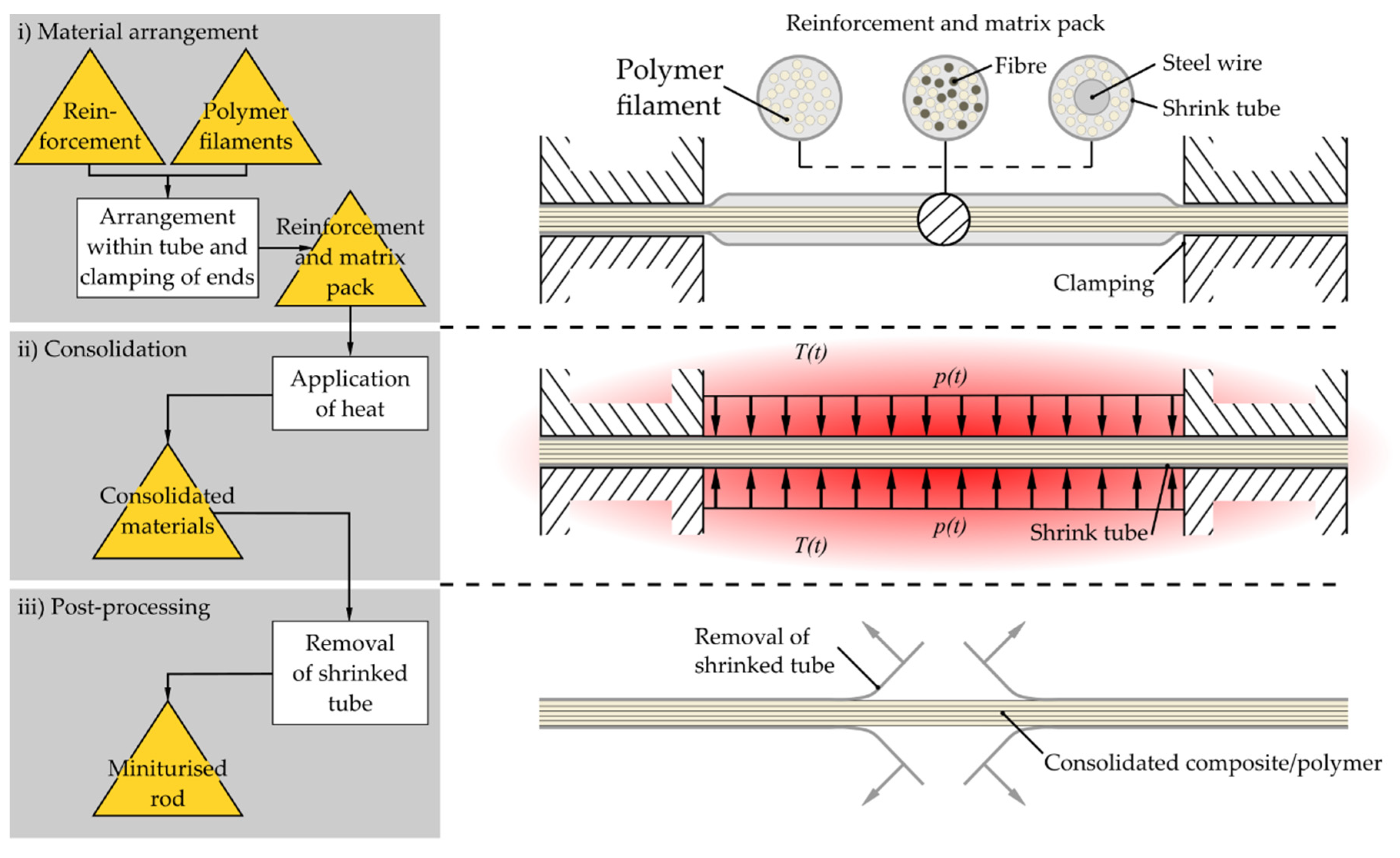
2.1.1. Shaping by Compression of Heat-Shrinkable Tubes—Shrink Tube Consolidation

In the present study, a new manufacturing method, called STC, was introduced. Therefore, conventional available heat-shrinkable tubes (PTFE 200-AWG 30 TW and PTFE 400-5/64, BIT Bierther GmbH, Swisttal-Heimerzheim, Germany) with an initial inner diameter of 0.86 and 2 mm and an inner diameter after shrinkage of 0.38 and 0.63 mm, respectively, were used for the shaping and compression of the reinforcement and matrix pack. The basic materials (roving and polymer filaments, pre-impregnated roving, steel wire and polymer filaments) were manually introduced into the heat-shrinkable tube (refer Figure 2). Since the glass fibre roving tended to fray, especially at the ends, the roving was inserted as one part and the polymeric filaments were arranged around it. Thus, an exact premixing to obtain a homogeneous distribution of reinforcement fibres and polymeric filaments was not given.
In the case of pre-impregnated tapes, the tapes were cut parallel to fibre direction and arranged as a stack. The arrangement was clamped at its ends and heated within a furnace up to temperatures slightly above the polymer’s melting temperature. Due to heating, the thermoplastic polymer within the shrink tube melted and the diameter of the tube decreased. Thus, the material arrangement was compressed and the fibres were impregnated or wires were coated by polymeric matrix material. After cooling, the melted polymer solidified and the tube’s inner surface produced a smooth specimen’s outer surface. At the end, the tube was carefully removed.
During the STC process, the heat-shrinkable tubes on the one hand compressed the reinforcement and matrix pack and on the other hand it had the task of a bagging film to obtain a smooth surface. Depending on the used reinforcement and matrix combination, a low as well as a high fibre volume content can be realised. The compression and thus the impregnation quality as well as the geometric shape of the resulting tube varied with the volume of the basic materials (reinforcement fibre, polymer filament, steel wire, pre-impregnated tape), the maximum process temperature T , its holding time t , the tube’s melting temperature and its consolidation. It should be noted that the maximum temperature was restricted by the thermal decomposition of PTFE and the specified application temperature range of the shrink tube. To avoid the contamination of the surrounding air by means of toxic PTFE thermal decomposition products, all manufacturing tests were performed under a laboratory fume hood and below the decomposition temperature of PTFE, ranging between 450 and 500 °C [18,19].
During the STC process, the impregnation of the composite was optimised by varying the cross-sectional area of reinforcement fibres/steel wire, denoted as area A r , and polymer filaments, denoted as area A p . Furthermore, analysing the resulting semi-finished products, the optimised maximum process temperature T and the required holding time t were determined. The temperature rise of each STC process was carried out with a temperate rate of 5 K/min. All manufacturing tests were performed at ambient conditions in air.

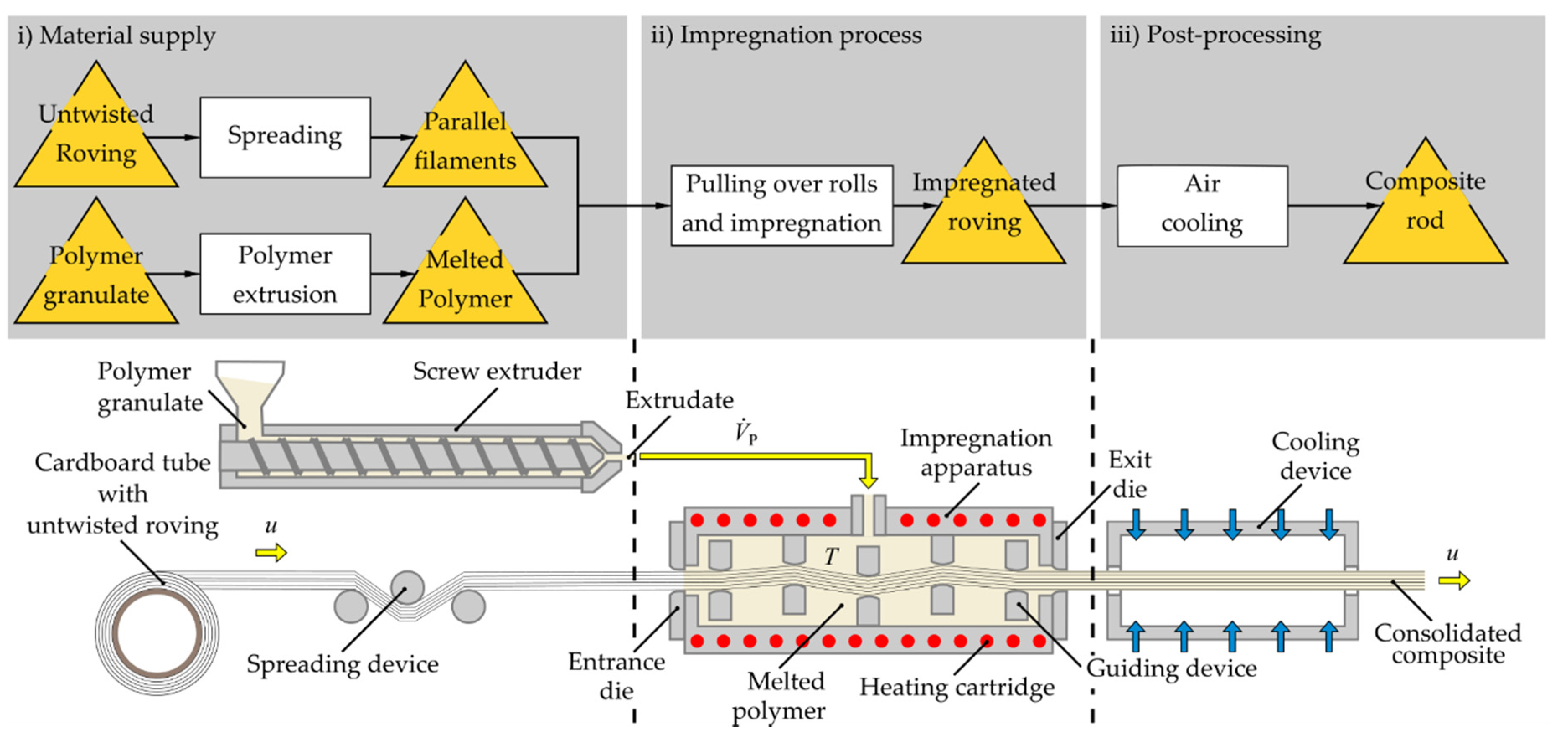
2.1.2. Thermoplastic Micro-Pultrusion

A conventional TPP process, such as that described by Garthaus et al. [2] and Hufenbach et al. [3] for the fabrication of pre-impregnated tapes, was adapted to manufacture rod-shaped round composite profiles. Therefore, a glass fibre roving was spread and led to an impregnation apparatus. The impregnation apparatus was connected with a screw extruder supplying a constant volumetric flow rate V P ˙ of melted polymer. A glass fibre roving with a silane sizing compatible with polyamide engineering thermoplastic polymers was used. The roving provided from a bundle of untwisted filaments was moved by a pulling machine through a round entrance die with a minimum diameter of 1 mm into the impregnation apparatus over a number of guiding devices with a nominal pulling speed u in the range of 0.25 to 3 m/s including a velocity, which can be reproduced with the existing equipment and which covers the widest possible range from slow to fast pulling speed. The die had a maximum diameter of 3 mm at the side of the incoming roving. This diameter was reduced over a length of 3 mm with corner radius of 5 mm and ended up at the nominal diameter of the die of 1 mm. The segment of the minimum diameter had a length of 2 mm (Figure 3).
The chamber of the impregnation machine was filled with melted polymer at melting temperature according to supplier’s recommendations (see Figure 4). The impregnation occurred during the contact of the roving with the guiding devices, where the fibres were spread out and opened up to receive the melted polymer (compare [15]). During the redirection, the fibres were parallel to each other. Between the fibres and the melted polymer, high local shear rates resulted in high shear forces. The redirection of the roving at the guiding devices, as well as the increase in pulling speed, increased the total perceived viscous drag. The total shear force and the required thread tension resulted in a pulling stress which had to be less than the roving’s tensile strength. The impregnated roving was pulled through a round exit die with the same diameter as the entrance die to remove excessive polymer. Afterwards, the impregnated fibres were air cooled to ambient temperature. At the end, the pultruded profile was wound on cardboard tube with very high diameter.
The micro-pultrusion was carried out with the thermoplastic polymer PA6 (Table 1). The inner pressure of the impregnation apparatus was 6 or 15 bar, respectively. The pressure was related to the temperature inside the impregnation apparatus as well as the volumetric flow rate of the inflow and outflow. For variation of viscous drag between fibres and melted thermoplastic polymer, different pulling speeds were investigated.

2.2. Investigated Basic Materials and Preparation of Specimens

In the present study, different self-manufactured and conventionally available semi-finished products (neat thermoplastics polymers, fibre reinforced thermoplastics, fibre reinforced thermosets, steel wire reinforced thermoplastics) were investigated. The required basic materials as well as the investigated conventional available semi-finished products are summarised and classified in the following table:
A glass fibre roving was impregnated with melted PA6 to manufacture a continuous glass fibre (GF)-reinforced PA6 by using TPP (TPP-GF/PA6). Furthermore, the same glass fibre roving and PEEK filament were combined to continuous fibre-reinforced PEEK by means of STC (STC-GF/PEEK). A stainless steel wire was combined in one configuration with PEEK filament (STTFF-1.4301/PEEK) and in another configuration with polytetrafluoroethylene (PTFE) tube by using the manufacturing method STC (STC-1.4301/PTFE). The STC process was also applied to manufacture neat PEEK rods (STC-PEEK). Pre-impregnated tapes made of carbon fibre (CF)-reinforced PEEK were used to fabricate solid composite rods by means of STC (STC-CF/PEEK). Carbon fibre-reinforced epoxy resin (TSP-CF/EP) and glass fibre-reinforced epoxy resin (TSP-GF/EP) manufactured in TSP process were analysed as delivered by the supplier.
Each semi-finished product obtained from self-implemented manufacturing process as well as the conventional available composite rods were trimmed to a length of 30 mm by means of a diamond cutting disc. Afterwards, all specimen were visually observed to detect visible manufacturing defects.
For a more detailed analysis of the manufacturing quality of the different semi-finished products, the prepared cutting surfaces were examined by means of reflected-light microscopy. For microscopic examinations, representative segments of each semi-finished product were embedded in cold mounting resin (CMR) and polished using a motorised polishing wheel.
The resulting grey-scale images were analysed using the Image Processing Toolbox of the numerical computing software (MATLAB 9.5 v.1.8; MathWorks, Inc., Natick, MA, USA). Using the implemented trace region boundaries algorithm, the cross-sectional dimensions of the outer contour as well as the area fraction of total fibre area to the total cross section, in the following denoted as fibre volume content V f , were determined. The roundness of the different specimens was analysed using the inverse fractal diameter δ = 4 π A / U 2 , where U was the cross-sectional perimeter of the cutting surface and A was its cross-sectional area. The fractal dimension obtained a value of δ = 1 for a perfect circular shape, while non-circular shapes obtained smaller fractal dimensions. Furthermore, the equivalent diameter D e 2 = 4 A / π was determined to obtain the dimensions of a circle equivalent to the specimen’s cross-section.

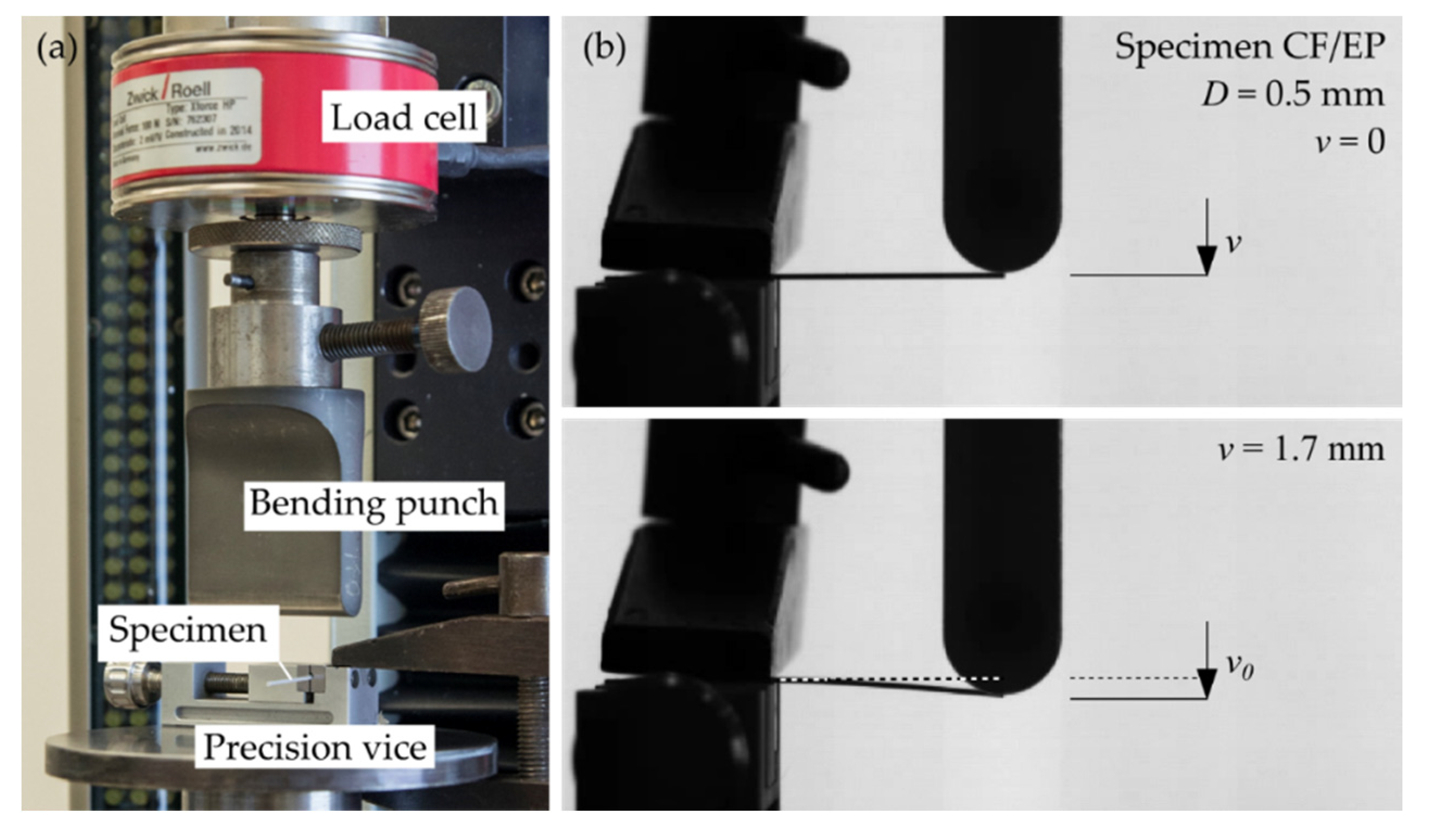
2.3. Experimental Determination of Flexural Modulus

For the determination of the flexural modulus, a two-point flexural test was carried out. Each miniaturised beam was manually clamped in a miniature precision vice for clamping small components and deflected by means of a bending punch with a radius of 5 mm using a testing speed of 1 mm/s (see Figure 5). The distance between clamping and the force transmission point of the applied load had a distance of L = 20   mm . The punch was fixed to a universal testing machine (AllroundLine Z250, ZwickRoell, Ulm, Germany), and the force was measured using a load cell (Xforce HP, ZwickRoell, Ulm, Germany) with a measurement range up to 100 N. The deflection was measured by the machine’s traverse path sensor.
Using the cross-sectional dimensions of the round single clamped beams, the deflection at the force transmission point v ( F 0 ) as a function of the concentrated load F 0 was determined. The bending stress σ f = σ z according to Equation (A4) in Appendix A and the bending strain ε f = ε z as described in Equation (A5) was calculated for a the measured specimen’s diameter and the constant distance L between clamping and the location of the applied force. Considering only bending strains up to ε f = 0.25 % , the flexural modulus was calculated as following:
E f = Δ σ f Δ ε f
where Δ σ f = σ | ε f = 0.25 % σ | ε f = 0.05 % and Δ ε f = 0.25 % 0.05 % = 0.2 % (comparable to the approach as described in DIN EN ISO 178). Since a computerised test equipment existed, the determination of the modulus E f using two different stress–strain points may be replaced by a linear regression method applied to the part of the curve between these two points of bending strain. Previously to testing, all specimens were stored at standard atmospheres for the conditioning and testing of plastics according to DIN EN ISO 291.
A statistical analysis was performed using statistical analysis software (PASW v.18; IBM Corporation; Armonk, New York, NY, USA) with significance set as probability value of P < 0.05 . One-way ANOVA was used to test differences in flexural modulus between the 10 fabricated rod-shaped round specimens (study groups). Between the groups, comparisons were performed using Bonferroni-corrected post hoc tests.

3. Results and Discussion

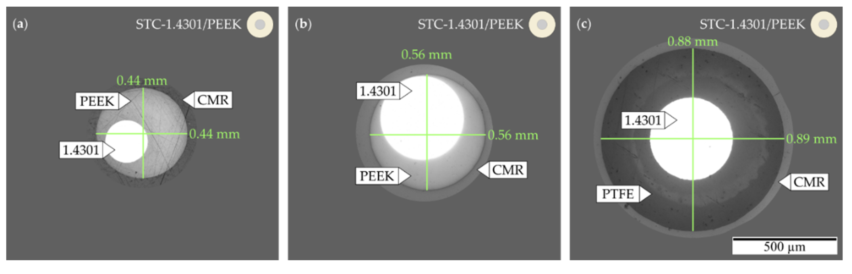
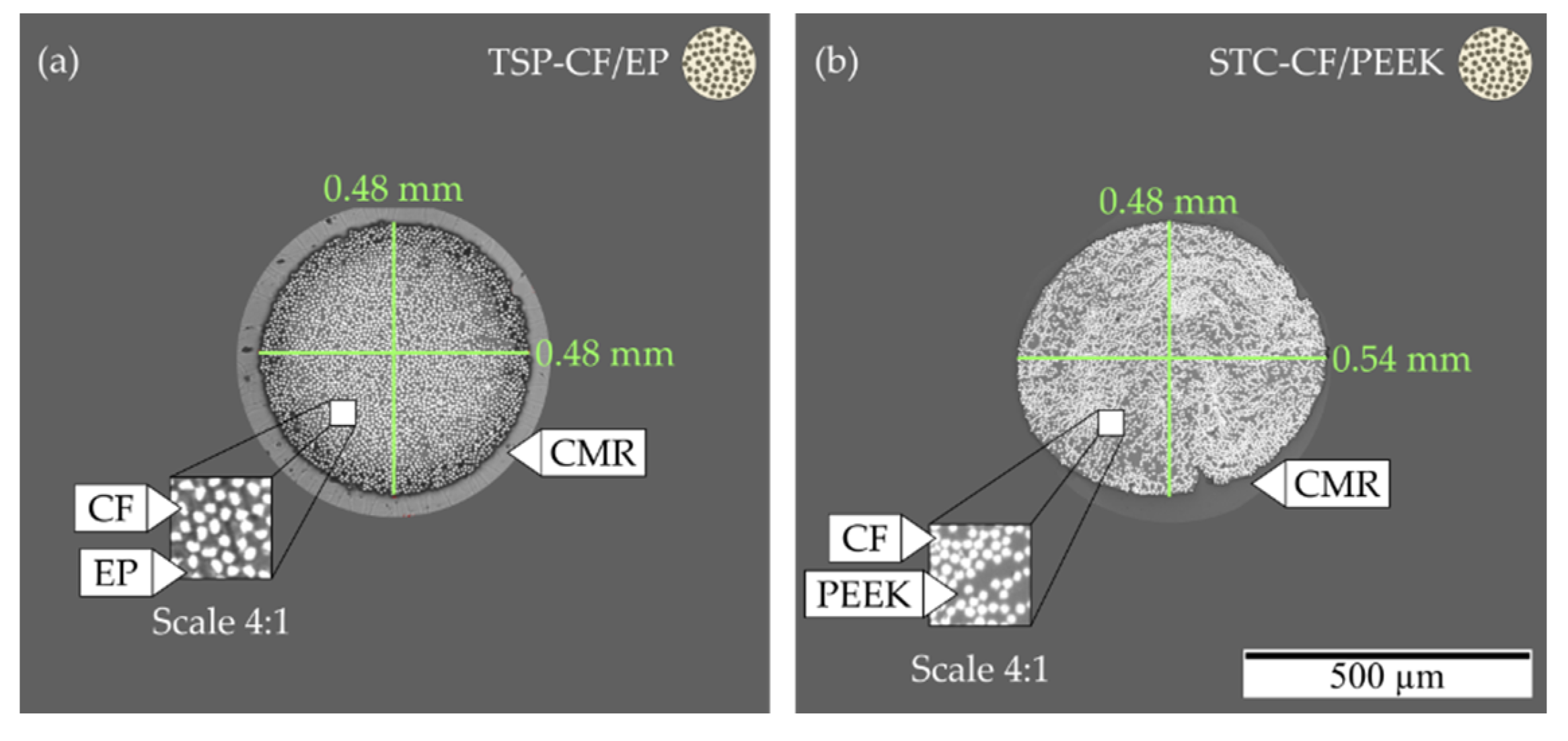
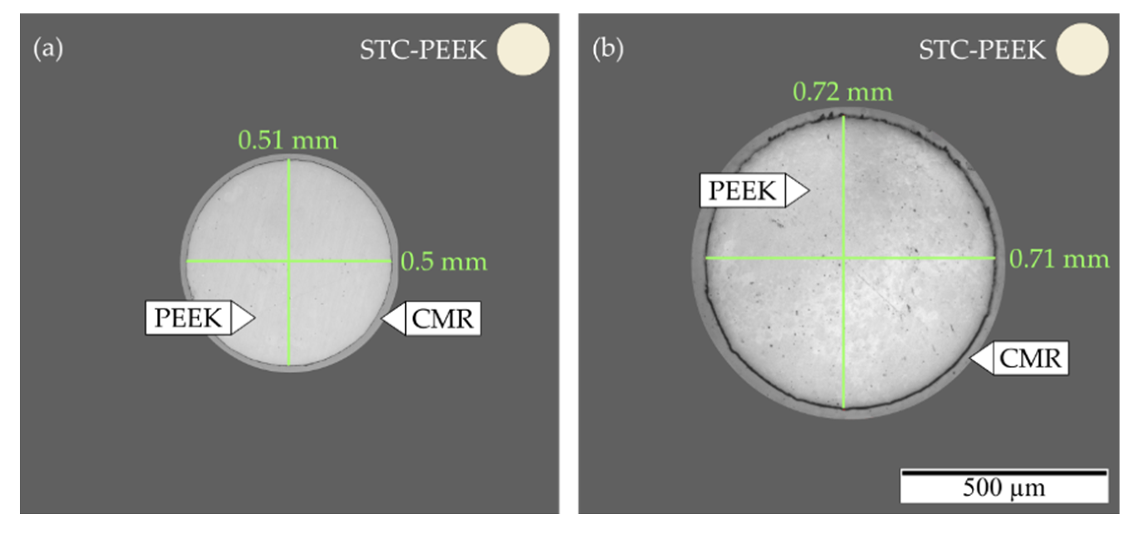
3.1. Resulting Cross-Sectional Properties of Manufacturing Related Parameters

3.1.1. Selection of Parameters of Shrink Tube Consolidation

The furnace temperature and holding time was chosen to ensure a reliable melting and compression of thermoplastic polymers (compare Table 2). For the shrinkage of PTFE, a temperature of more than 327 °C should be used [20] and for PEEK, the melting point is between 335 and 340 °C [21]. The lowest manufacturing effort was required for the stainless steel wire reinforced polymer 1.4301/PTFE, where the shrinkage tube was not removed at the end of the manufacturing process, i.e., the tube represented the outer layer. This approach obtained a central-aligned steel wire, whereas the combination of PEEK filament and steel wire could result in a non-centred wire reinforcement. A twist of the polymeric filament with an angle of approximately 10° according to the wire’s central axis improved the alignment; however, the twisting was not able to eliminate the misalignment. Analogously, the impregnation of glass fibre and PEEK filament showed a high concentration of fibres at one side of the specimen’s outer contour. The usage of pre-impregnated tapes resulted in a high fibre volume content; however, it also showed a lower level of roundness. The implemented STC was restricted by the available diameter of shrink tube as well as the amount of material supported by the inserted reinforcement and matrix pack. Even though, the STC process resulted in semi-finished products with a smooth outer surface and a level of roundness of its cross section, but at same time, it required a high manual effort to arrange the basic material within the shrink tube as well as the removal of shrink tube at the end of the process. Nevertheless, this approach allows an easy-to-implement process for the manufacturing of miniaturised fibre-reinforced and wire-reinforced thermoplastic polymers. This method is also applicable for reinforced thermosetting polymers, but this approach was not carried out for the present study. Generally, the method STC enables the manufacturing of miniaturised round profiles with a high variability of used material combinations.

3.1.2. Selection of Parameters of Thermoplastic Micro-Pultrusion

The forming and compressing of GF/PA6 by continuously pulling through a die obtained an equivalent diameter of the semi-finished products between 1 and 1.08 mm depending on the applied nominal pulling speed and the impregnations apparatus inner pressure (see Table 3). During the pultrusion tests, the inner pressure p was classified in two groups (low pressure level, p = 6   ±   4.3   bar ; high pressure level, p = 15   ±   5.2   bar ) (Table 3). The inner pressure was controlled by adjustment of the screw extruder’s outflow of melted polymer. Temperature inside the impregnation apparatus was set to at least 220 °C according to suppliers recommendations [22]. A pulling speed of v = 0.25   m / s as well as the application of the high inner pressure level obtained a high fibre volume content as well as a round cross-sectional shape of the solid rod (compare Table 3). In contrast, high velocities especially in presence with small inner pressure obtained an irregular cross-sectional shape and a rough outer surface. On the one hand, the local viscous drag, especially at the guiding devices within the impregnation apparatus, increases with increasing pulling velocity, but on the other hand, the increased velocity influences the removal of excessive polymer at the exit die and the time of residency of the fibre bundle, and the individual fibres will be closer to each other due to increased pulling force [23]. Babeau et al. [23] figured out that the die geometry, such as the taper angle and the taper length, had the main influence on the profile’s degree of saturation during direct injection-pultrusion process of thermoplastic composites. They analysed pulling speeds between 0.002 and 0.02 m/s for the manufacturing of more complex flat and omega profiles and without guiding devices inside the impregnation apparatus. For this velocity range, there was no difference in saturation distributions. One geometry was used for entrance and exit die, which minimised the material leakage of melted polymer, the insertion of the unsaturated fibre bundle as well as a sliding without resistance and the reliable drawing in of individual broken fibres. Further improvements by the optimisation of exit die’s geometry and the reduction in the pulling speed seems to be possible to obtain a better saturation of the profile, a higher level of roundness and a smoother surface. Nevertheless, in the following, the minimum velocity u = 0.25   m / s and the application of a pressure of p = 15   ± 5.2   bar were used to manufacture the specimens made of GF/PA6. For the investigated process parameters, these values obtained specimens with the best impregnation and smoothest outer surface.

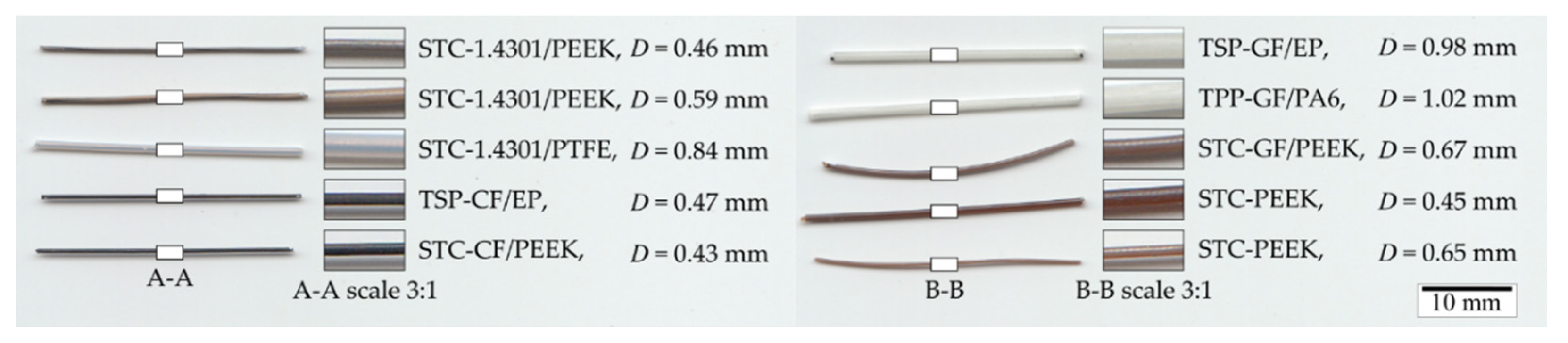
3.2. Investigated Semi-Finished Products and Measurements of Flexural Modulus

The solid rods manufactured by means of pultrusion (TPP, TSP) had a high straightness due to the applied thread tension during the entire cooling process (compare Figure 6). In contrast, the specimen fabricated by STC could be partly curved depending on the used materials, the maximum process temperature and the decrease in temperature during the cooling process. Consequently, the occurrence of thermally induced residual stress cannot be excluded, but has not been quantified more precisely within the framework of the current investigation. Furthermore, the position of reinforcement and polymeric matrix influenced the curvature, such as visible in the case of STC-GF/PEEK. Nevertheless, for the determination of mechanical characterisation, segmentally straight sections were selected from the entirety of manufactured specimens and mechanically characterised.
The conventional solid rods made of CF/EP and GF/EP showed a high level of roundness as well a homogeneous distribution of impregnated fibres. The STC process obtained a good roundness for the rods made of wire reinforced polymers 1.4301/PEEK, 1.4301/PTFE, fibre reinforced composites GF/PEEK and neat PEEK (Figure 7, Figure 8, Figure 9 and Figure 10). However, as described above the alignment of the reinforcement was not exactly in the cross section’s middle and inhomogeneous over the whole cross section for the wire reinforced or the glass fibre reinforced polymers, respectively (compare Figure 7a,b and Figure 9c).
If properly applied, the STC process allowed a good impregnation as well as reliable thermal process control. The resulting specimen manufactured by micro-pultrusion showed a good impregnation and a high fibre volume content but a reduced level of roundness and outer contour’s surface quality for the implemented prototypical manufacturing apparatus.
For the statistical comparison of bending properties, the miniaturised rod-shaped specimens were considered as ideal round ( δ 0.95 , compare Table 4). The measured flexural moduli represented the effective moduli of the different wire reinforced and fibre reinforced polymers (Table 4). It should be noted that the optically measured fibre volume content represented sectional observation of cross-sectional properties and that the fraction of imperfections, such as foreign particles or air pockets, was not considered and can change over the specimen’s length. Nevertheless, for the investigated specimens, a homogeneity was assumed. The bending stresses were considered as linear for a bending strain range between ε f = 0.05 % and ε f = 0.25 % (compare Figure 11). Due to non-elastic effects, such as viscoelasticity and the modification of applied load’s location as well as its direction, a degressive curve resulted for higher bending strains, which were not analysed in the present study.
The statistically analysis of the resulting flexural moduli obtained different mean values. There was a statistically significant difference between the groups as determined by one-way ANOVA F ( 10 , 54 ) = 141.626 , P < 0.01 , η p 2 = 0.96 , ω 2 = 0.96 . A Bonferroni post hoc test revealed that the flexural modulus of CF/PEEK (134.2 ± 12.56 GPa) and of CF/EP (115 ± 15.81 GPa) were statistically significantly higher than the modulus of all other investigated specimens ( P < 0.001 ). The flexural modulus of neat PEEK with a diameter of D = 0.45   mm (5.8 ± 0.89 GPa) and D = 0.66   mm (4.9 ± 0.65 GPa) showed no significant difference ( P = 1 ). There was no statistically significant difference between the glass fibre reinforced polymers GF/EP (21.9 ± 3.3 GPa) and GF/PA6 (28.9 ± 4.89 GPa) ( P = 1 ), whereas composite GF/PEEK (10.4 ± 2.1 GPa) was significantly different compared to the fibre reinforced polymer GF/PA6 ( P = 0.022 ) and was not significantly different compared to the material GF/EP ( p = 1 ). The wire reinforced polymer 1.4301/PEEK with a diameter of D = 0.46   mm (12.9 ± 1.71 GPa) and 1.4301/PTFE (8.27 ± 1.71 GPa) had statistically equal flexural modulus ( P = 1 ), however there was a significant difference compared to the material 1.4301/PEEK with a diameter of D = 0.59   mm (40.4 ± 8.4 GPa, P < 0.001 ). Taking the different materials and manufacturing methods into consideration, the statistical comparison of the mean values of the measured flexural modulus resulted in the following findings:
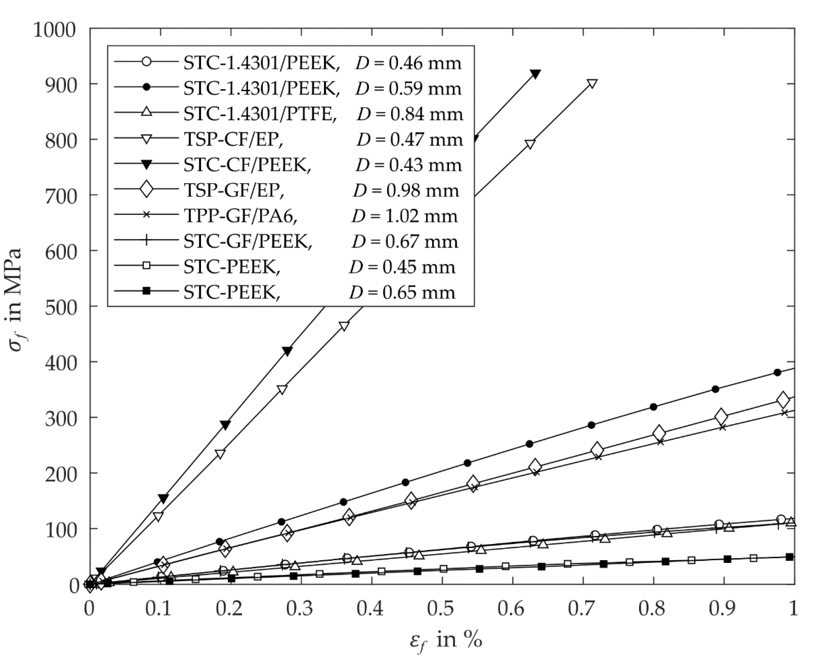
  • The used fibre/wire reinforcement and fibre volume content of the composites mainly influences elastic modulus of the fabricated specimens (compare TSP-CF/EP and STC-CF/PEEK, Figure 11).
  • The manufacturing of semi-finished products with different diameters using the STC process show no significant difference in the elastic properties (compare STC-PEEK Figure 11).
  • Solid rods manufactured by means of the STC process resulted in a smooth external surface (see STC-GF/PEEK, Figure 9c).
  • After the implementation of a pultrusion process (TSP, TPP), large quantities of continuous composite profiles with a high degree of straightness can be fabricated for low costs within short times.
Summarising all the findings of the present study, the introduced STC process appears to be a promising process variant for the producing of small quantities of miniaturised composite rods at a low manufacturing readiness level (MRL). By using this process, preliminary investigations for the development of different fibre/matrix composite materials can be carried out in a cost- and resource-efficient way due to a low manufacturing effort and a minimised material usage.

4. Conclusions

Two manufacturing methods for the fabrication of miniaturised solid rods made of reinforced polymer were successfully implemented. Using an experimental survey, suitable manufacturing parameters were determined for the development of prototypical manufacturing processes. The shaping by compression of heat-shrinkable insulation tubes enabled a simple production with low manufacturing effort for small quantities of specimens in a cost- and resource-efficient way, whereas the application of thermoplastic pultrusion produced high quantities of reliable impregnated composite structures. However, the complexity and costs for manufacturing and equipment significantly increase for the application of pultrusion processes.

Author Contributions

Conceptualisation, M.K. and M.D.; methodology, M.K.; software, validation and formal analysis, M.K.; experimental investigation, M.K. and A.H.; manufacturing and product testing, A.H., M.K. and A.W.; writing—original draft preparation, M.K. and M.D.; writing—review and editing, M.K., M.D., A.W. and A.H.; visualization, M.K.; supervision, M.D.; project administration, N.M. and M.D. All authors have read and agreed to the published version of the manuscript.

Funding

This research was funded by the German Research Foundation (grant no. DA 1701/1).

Acknowledgments

The authors acknowledge the technical support and inspirational discussions of Alexander Rohkamm on the pultrusion process of fibre reinforced thermoplastic solid rods.

Conflicts of Interest

The authors declare no conflict of interest related to the present study.

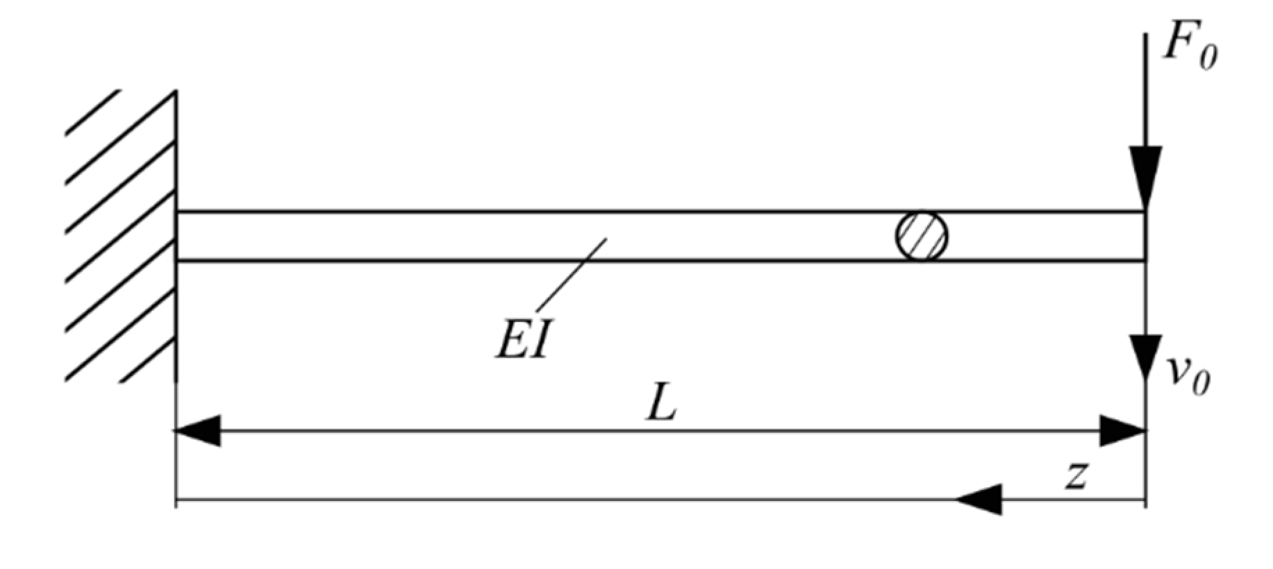
Appendix A. Mechanical Description of Bending Stress and Strain for A Single Clamped Cantilever Beam

Assuming the Euler–Bernoulli beam theory, a homogeneous linear elastic material behaviour in beam direction and constant cross-sectional dimensions along the z -axis, the static beam equation was used to determine the deflection of a single clamped cantilever beam (Figure A1).
Figure A1. Schematic of round single clamped cantilever beam with a constant diameter D (small cross-sectional dimensions D / L 1 ) and a homogenous material distribution.
Jcs 04 00084 g0a1
The balance of moment at the cut surface obtained the bending moment and yielded the maximum bending stress in the clamping as following:
σ z = F 0 L I x x y
where F 0 was a concentrated load, L was the beam’s length, I x x was the moment of inertia and y was the coordinate along the beam’s height direction. The deflection in the force transmission point v ( z = 0 ) = v 0 was described by the following equation [24]:
v 0 = F 0 L 3 3 E I x x
Using Equation (A1), the bending strain was identified in equation (A2) satisfying the relationship between stress and strain σ z = E ε z as described by:
F 0 L I x x y σ z = E · 3 v 0 L 2 y ε z
For a round beam with a radius R = D / 2 , the maximum bending stress and strain were determined at the maximum distance in y -direction (beams out surface) as described by:
σ z ( y = | y | max = R ) = 4 F 0 L π R 3
ε z ( y = | y | max = R ) = 3 v 0 R L 2
The bending stress and the bending strain were denoted as σ f = σ z and ε f = ε z .

References

  1. Maron, B.; Garthaus, C.; Hornig, A.; Lenz, F.; Hübner, M.; Gude, M. Forming of carbon fiber reinforced thermoplastic composite tubes—Experimental and numerical approaches. CIRP-JMST 2017, 18, 60–64. [Google Scholar] [CrossRef]
  2. Garthaus, C.; Witschel, B.; Barfuß, D.; Rohkamm, A.; Gude, M. Funktionalisierte Faser-Thermoplast-Profilstrukturen. Lightweight. Des. 2016, 9, 40–45. [Google Scholar] [CrossRef]
  3. Hufenbach, W.; Garthaus, C.; Behnisch, T.; Witschel, B. European Patent Application—Pultrusion Methods and Arrangements for Manufacturing a Fibre-Reinforced Composite Product. Available online: https://worldwide.espacenet.com/patent/search/family/050033422/publication/EP2905122A1?q=pn%3DEP2905122A1 (accessed on 21 April 2020).
  4. Bhandari, S.; Lopez-Anido, R.A.; Gardner, D.J. Enhancing the interlayer tensile strength of 3D printed short carbon fiber reinforced PETG and PLA composites via annealing. Addit. Manuf. 2019, 30, 100922. [Google Scholar] [CrossRef]
  5. Somireddy, M.; Singh, C.V.; Czekanski, A. Mechanical behaviour of 3D printed composite parts with short carbon fiber reinforcements. Eng. Fail. Anal. 2020, 107, 104232. [Google Scholar] [CrossRef]
  6. Justo, J.; Távara, L.; García-Guzmán, L.; París, F. Characterization of 3D printed long fibre reinforced composites. Compos. Struct. 2018, 185, 537–548. [Google Scholar] [CrossRef]
  7. Stepashkin, A.A.; Chukov, D.I.; Senatov, F.S.; Salimon, A.I.; Korsunsky, A.M.; Kaloshkin, S.D. 3D-printed PEEK-carbon fiber (CF) composites: Structure and thermal properties. Compos. Sci. Technol. 2018, 164, 319–326. [Google Scholar] [CrossRef]
  8. Hufenbach, W.; Gottwald, R.; Markwardt, J.; Eckelt, U.; Modler, N.; Reitemeier, B. Berechnung und experimentelle Prüfung einer Implantatstruktur in Faserverbundbauweise für die Überbrückung von Kontinuitätsdefekten des Unterkiefers. Biomed. Tech. 2008, 53, 306–313. [Google Scholar] [CrossRef] [PubMed]
  9. Ehrig, T.; Koschichow, R.; Dannemann, M.; Modler, N.; Filippatos, A. Design and Development of an Active Wheelchair with Improved Lifting Kinematics Using CFRP-Compliant Elements. In Proceedings of the 18th European Conference on Composite Materials ECCM18, Athens, Greece, 24–28 June 2018. [Google Scholar]
  10. Neubauer, M.; Häntzsche, E.; Pamporaki, C.; Eisenhofer, G.; Dannemann, M.; Nocke, A.; Modler, N.; Filippatos, A. Development of a Function-Integrative Sleeve for Medical Applications. Sensors 2019, 19, 2588. [Google Scholar] [CrossRef] [PubMed] [Green Version]
  11. Brecher, C.; Emonts, M.; Brack, A.; Wasiak, C.; Schütte, A.; Krämer, N.; Bruhn, R. New concepts and materials for the manufacturing of MR-compatible guide wires. Biomed. Tech. 2014, 59, 147–151. [Google Scholar] [CrossRef] [PubMed]
  12. Kucher, M.; Dannemann, M.; Modler, N.; Hannig, C.; Weber, M.-T. Effects of Endodontic Irrigants on Material and Surface Properties of Biocompatible Thermoplastics. Dent. J. 2019, 7, 26. [Google Scholar] [CrossRef] [PubMed] [Green Version]
  13. Kirsch, J.; Reinauer, K.S.; Meissner, H.; Dannemann, M.; Kucher, M.; Modler, N.; Hannig, C.; Weber, M.-T. Ultrasonic and sonic irrigant activation in endodontics: A fractographic examination. Dtsch. Zahnärztl. Z. Int. 2019, 1, 209–221. [Google Scholar] [CrossRef]
  14. Brack, A.; Senger, S.; Fischer, G.; Janssen, H.; Oertel, J.; Brecher, C. Development of an artifact-free aneurysm clip. Curr. Dir. Biomed. Eng. 2016, 2, 24. [Google Scholar] [CrossRef] [Green Version]
  15. Tao, Z.; Wang, Y.; Li, J.; Wang, X.; Wu, D. Fabrication of long glass fiber reinforced polyacetal composites: Mechanical performance, microstructures, and isothermal crystallization kinetics. Polym. Compos. 2015, 36, 1826–1839. [Google Scholar] [CrossRef]
  16. Paužuolis, D. How to Make Shaped Carbon Fiber Rods. Available online: https://www.pauzuolis-rc.com/how-to-tips/make-shaped-carbon-fiber-rods (accessed on 25 March 2020).
  17. Starr, T.F. Pultrusion for Engineers, 1st ed.; CRC Press: Boca Raton, FL, USA, 2000; pp. 19–230. [Google Scholar]
  18. Wall, L.A.; Michaelsen, J.D. Thermal decomposition of polytetrafluoroethylene in various gaseous atmospheres. J. Res. Natl. Bur. Stand. 1956, 56, 27–34. [Google Scholar] [CrossRef]
  19. Hondred, P.R.; Yoon, S.; Bowler, N.; Kessler, M.R. Degradation kinetics of polytetrafluoroethylene and poly(ethylene-alt-tetrafluoroethylene). High. Perform. Polym. 2013, 25, 535–542. [Google Scholar] [CrossRef]
  20. Bit Bierther GmbH. PTFE 400 Heat-Shrinkable Tube Made from Polytetrafluorethylene. Available online: https://www.bit-gmbh.de/en/product/ptfe-400.html (accessed on 21 April 2020).
  21. Jaffe, M.; Menczel, J.D. Thermal Analysis of Textiles and Fibers, 1st ed.; Woodhead Publishing: Duxford, UK, 2020; pp. 247–254. [Google Scholar]
  22. Solvay Engineering Plastics. Product Data Sheet TECHNYLSTAR. Available online: www.rhodia.com (accessed on 18 February 2015).
  23. Babeau, A.; Comas-Cardona, S.; Binetruy, C.; Orange, G. Modeling of heat transfer and unsaturated flow in woven fiber reinforcements during direct injection-pultrusion process of thermoplastic composites. Compos. Part A Appl. Sci. Manuf. 2015, 77, 310–318. [Google Scholar] [CrossRef] [Green Version]
  24. Balke, H. Einführung in die Technische Mechanik, 1st ed.; Springer: Berlin/Heidelberg, Germany, 2010; pp. 82–110. [Google Scholar]
Figure 1. Overview of the investigated manufacturing methods and the fabricated semi-finished products.
Jcs 04 00084 g001
Figure 2. Process chain of shaping by compression of heat-shrinkable tube—shrink tube consolidation (STC): process diagram (left) and schematic of manufacturing steps (right).
Jcs 04 00084 g002
Figure 3. Cross-sectional dimensions of the entrance and exit die of the thermoplastic pultrusion apparatus.
Jcs 04 00084 g003
Figure 4. Process chain of thermoplastic pultrusion: process diagram (top) and schematic of manufacturing steps (bottom).
Jcs 04 00084 g004
Figure 5. (a) Experimental setup for determination of flexural modulus and (b) exemplary illustration of a beams deflection as described by means of the static beam equation.
Jcs 04 00084 g005
Figure 6. Selection of investigated specimens. Abbreviation: carbon fibre (CF), epoxy resin (EP), glass fibre (GF), shrink tube consolidation (STC), thermoplastic pultrusion (TPP), thermoset pultrusion (TSP), polyamide (PA), polyether ether ketone (PEEK), polytetrafluoroethylene (PTFE). The detail views A-A and B-B of the different specimens were visualised with a triple magnification.
Jcs 04 00084 g006
Figure 7. Photomicrographs of wire reinforced polymers manufactured by means of shrink tube consolidation (STC) embedded in cold mounting resins (CMR): (a) stainless steel 1.4301/polyether ether ketone (PEEK), D = 0.46 mm; (b) 1.4301/PEEK, D = 0.59 mm; (c) 1.4301/polytetrafluoroethylene (PTFE), D = 0.84 mm.
Jcs 04 00084 g007
Figure 8. Photomicrographs of carbon fibre (CF) reinforced polymers manufactured by means of thermoset pultrusion (TSP) and thermoplastic pultrusion (TPP) embedded in cold mounting resins (CMR): (a) CF/epoxy resin (EP), D = 0.47 mm; (b) CF/polyether ether ketone (PEEK), D = 0.43 mm.
Jcs 04 00084 g008
Figure 9. Photomicrographs of investigated specimens made of glass fibre (GF) reinforced polymers manufactured by means of thermoset pultrusion (TSP) and thermoplastic pultrusion (TPP) embedded in cold mounting resins (CMR): (a) GF/ epoxy resin (EP), D = 0.98 mm; (b) GF/polyamide (PA)6; D = 1.02 mm; (c) GF/polyether ether ketone (PEEK), D = 0.67 mm.
Jcs 04 00084 g009
Figure 10. Photomicrographs of investigated specimens made of neat polymer manufactured by means of shrink tube consolidation (STC) embedded in cold mounting resins (CMR): (a) polyether ether ketone (PEEK), D = 0.45 mm; (b) PEEK, D = 0.65 mm.
Jcs 04 00084 g010
Figure 11. Averaged curve of bending stress of the different investigated wire and fibre reinforced polymer. Abbreviation: carbon fibre (CF), epoxy resin (EP), glass fibre (GF), shrink tube consolidation (STC), thermoplastic pultrusion (TPP), thermoset pultrusion (TSP), polyamide (PA), polyether ether ketone (PEEK), polytetrafluoroethylene (PTFE).
Jcs 04 00084 g011
Table 1. Required basic materials and investigated conventional available semi-finished products.
MaterialFormType 1Product NameSupplier
cfwp
1.4301Wire x Steel wireAlthoff + Lötters, Iserlohn, Germany
CF/EPSolid rodx DPP Carbon round solid rodR&G Faserverbundwerkstoffe, Waldenbuch, Germany
CF/PEEKTapex Tenax-E TPUD PEEK-IMS65Toho Tenax Europe, Wuppertal, Germany
GFRoving x StarRov 890 1200Johns Manville, Denver, USA
GF/EPSolid rodx Glass fibre rodR&G Faserverbundwerkstoffe, Waldenbuch, Germany
PA6Granulate xTECHNYLSTAR XS 1352 BL Solvay Engineering Plastics, Freiburg, Germany
PEEKFilament xZyex fibres 230f30Zyex, Gloucestershire, UK
PTFETube xPTFE 200 and 400BIT Bierther, Swisttal-Heimerzheim, Germany
Abbreviations: carbon fibre (CF), epoxy resin (EP), glass fibre (GF), polyamide (PA), polyether ether ketone (PEEK), polytetrafluoroethylene (PTFE). 1 The used basic materials were classified as composite c, fibre f, steel wire w and polymer p.
Table 2. Parameters of shrink tube consolidation and resulting semi-finished product’s dimensions (mean ± standard deviation).
Reinforcement1.43011.43011.4301CFGF--
PolymerPEEKPEEKPTFEPEEKPEEKPEEKPEEK
Process parameter
Temperature
T in °C
355355 350350350350350
Holding time
t in min
2020 520202020
Shrink tube diameter
D 0 in mm
0.8620.860.8620.862
Theoretical preliminary design
Area reinforcement
A r in mm²
0.030.130.130.120.06--
Area polymer
A p in mm²
0.150.20.460.090.290.180.36
Nominal diameter
D n in mm
0.480.650.860.50.660.480.68
Nominal volume fibre content
V f , n in %
1838225917--
Measurements
Measured diameter
D m mm
0.46 ± 0.010.59 ± 0.030.84 ± 0.010.43 ± 0.040.67 ± 0.030.45 ± 0.020.66 ± 0.06
Volume fibre content
V f in %
19 ± 1.456 ± 1.920 ± 0.344 ± 3.226 ± 3.4--
Fractal diameter
δ
0.99 ± 0.010.99 ± 0.010.99 ± 0.010.95 ± 0.020.99 ± 0.010.99 ± 0.010.98 ± 0.01
Equivalent diameter
D e in mm
0.47 ± 0.020.54 ± 0.010.89 ± 0.010.52 ± 0.010.7 ± 0.010.49 ± 0.030.69 ± 0.03
Abbreviations: Carbon fibre (CF), glass fibre (GF), polyether ether ketone (PEEK), polytetrafluoroethylene (PTFE).
Table 3. Parameters of thermoplastic micro-pultrusion and analysis of semi-finished product’s resulting cross section for the pultrusion of polyamide PA6 with continuous glass fibre reinforcement (mean value ± standard deviation).
Nominal Pulling Speed
u in m/s
Inner Pressure
p in bar 1
Fibre Volume Content
V f   in   %
Fractal Diameter
δ
Equivalent   Diameter   D e   in   mm
0.256 ± 4.358 ± 0.70.87 ± 0.041.01 ± 0.01
0.2515 ± 5.257 ± 1.10.83 ± 0.011.01 ± 0.01
0.56 ± 4.359 ± 70.69 ± 0.281 ± 0.06
0.515 ± 5.256 ± 1.40.91 ± 0.031.02 ± 0.01
16 ± 4.350 ± 1.40.9 ± 0.031.08 ± 0.03
115 ± 5.250 ± 3.20.55 ± 0.11.05 ± 0.04
1.515 ± 5.2n/a 1n/a 1n/a 1
215 ± 5.2n/a 1n/a 1n/a 1
315 ± 5.2n/a 1n/a 1n/a 1
1 There was no regular boundary of specimen identified.
Table 4. Manufacturing method and material properties of the investigated miniaturised rod-shaped wire reinforced and fibre reinforced polymers (mean value ± standard deviation).
Material 1Manufacturing Method Diameter   D   in   mm Fibre Volume Content
V f   in   %
Fractal Diameter
δ
Effective
Flexural   Modulus   E f   in   GPa
1.4301/PEEKSTC0.46 ± 0.00619 ± 1.40.99 ± 0.0112.9 ± 1.71
STC0.59 ± 0.02956 ± 1.90.99 ± 0.0140.4 ± 8.4
1.4301/PTFE 1STC0.84 ± 0.00720 ± 0.30.99 ± 0.018.27 ± 1.71
CF/EPTSP0.47 ± 0.00456 ± 4.10.95 ± 0.06115 ± 15.81
CF/PEEKSTC0.43 ± 0.03544 ± 3.20.95 ± 0.02134.2 ± 12.56
GF/EPTSP0.98 ± 0.00251 ± 1.80.99 ± 0.0121.9 ± 3.3
GF/PA6TPP1.02 ± 0.02457 ± 1.10.83 ± 0.0128.9 ± 4.89
GF/PEEKSTC0.67 ± 0.02626 ± 3.40.99 ± 0.0110.4 ± 2.1
PEEKSTC0.45 ± 0.021-0.99 ± 0.015.8 ± 0.89
STC0.66 ± 0.056-0.98 ± 0.014.9 ± 0.65
Abbreviation: carbon fibre (CF), epoxy resin (EP), glass fibre (GF), shrink tube consolidation (STC), thermoplastic pultrusion (TPP), thermoset pultrusion (TSP), polyamide (PA), polyether ether ketone (PEEK), polytetrafluoroethylene (PTFE); 1 The shrinkage tube itself represented the outer layer of the wire reinforced polymer and was not removed.

