Article

Tensile Properties of Z-Pin Reinforced Laminates with Circumferentially Notched Z-Pins

Department of Mechanical Engineering and Marine Technology, Chair of Lightweight Design and Materials, University of Rostock, Albert-Einstein-Str. 2, 18059 Rostock, Germany
*
Author to whom correspondence should be addressed.
J. Compos. Sci. 2020, 4(2), 78; https://doi.org/10.3390/jcs4020078
Submission received: 9 June 2020 / Revised: 19 June 2020 / Accepted: 21 June 2020 / Published: 23 June 2020
(This article belongs to the Special Issue Advanced Fiber Reinforced Polymer Composites)

Abstract

:
This paper describes experimental investigations on the in-plane tensile properties of unidirectional carbon-fibre/epoxy laminates reinforced with circumferentially notched z-pins with different notch designs. From the results it can be concluded that the application of circumferential notches at the z-pin surface with constant notch depth of 20 μm and distance of 100 μm has no significant effect on the in-plane tensile strength values, regardless of the notch designs investigated. For circular and rectangular notch designs, no dependence of the tensile strength from the notch depth could be observed. Only changing the notch distances at a constant notch depth and width leads to small increases in the tensile strength values with increasing notch distance. The determined tensile modulus values indicate that there are no substantial deviations between laminates reinforced with unnotched and circumferentially notched z-pins, no matter which notch design is considered. It can be observed that there are no dependencies of the tensile modulus from notch depth and distance. Therefore, it can be assumed that the microstructural changes influencing the in-plane tensile properties will not be changed, or only to a very small extent, by the presence of notches on the pin surface.

1. Introduction

Fiber-reinforced plastics have excellent lightweight properties, enabling significant resource and energy savings in applications such as aerospace and, increasingly, in automotive applications, especially in electromobility. These positive properties can be observed in the laminate plane in which the load-bearing fibres are aligned. Apart from these positive properties, unsatisfactory properties can also be described, such as insufficient delamination properties, which may result in delaminations between fibre layers under impact loading of the laminate. Under fatigue loading existing delaminations may grow and result in a complete structural collapse of the component, made of fibre-reinforced plastics. Numerous methods are available to enhance those disadvantageous properties. Apart from the use of thermoplastic or elastomeric particles in the primarily used thermoset matrices [1,2], there are a number of techniques to create a three-dimensional (3D) fibre structure counteracting these disadvantageous behaviour. These techniques used to create a three-dimensional fibre reinforcement include 3D-weaving- [3,4], 3D-knitting- [4,5] and braiding [6,7], in which a 3D fibre structure is created directly from the reinforcing fibres. Thus, these techniques belong to the category of the direct preforming methods [8]. In contrast, the 3D-stitching [4,9], tufting [10] and z-anchoring [11] belong to the multi-step preform processes. This requires intermediate steps for stacking the two-dimensional fibre materials and connecting them to each other to create 3D-fibre structures. These methods are not applicable to pre-impregnated fibre materials (prepreg). The only method used for three-dimensional reinforcement of structures made of prepreg materials is the z-pin technology [12]. Thin rod-shaped elements (pins), which are mainly made of high stiffness and high strength material, such as steel, titanium or carbon-fibre reinforced plastics (CFRP) with unidirectional fibre orientation, are inserted perpendicular to the laminate plane. Typically the diameter of the pins ranges from 0.1 to 1 mm and are used with a z-pin content of 0.5 to 5% [12]. However, there have also already been scientific studies in which z-pins with a rectangular cross-section geometry have been used, providing an enlarged surface area for bonding to the laminate without changing the size of cross-sectional area. Under delamination loading increased bridging effects can be achieved, which may lead to an improvement in delamination toughness [13,14]. Partridge et al. [15,16] give a comprehensive overview of the manufacture of z-pin-reinforced composite structures using the Ultrasonically Assisted Z-Fibre ™(UAZ) process, which is primarily used nowadays. The z-pins are subjected to ultrasonic vibration and driven into the uncured laminate under axial loading. The curing of the pinned laminate subsequently takes place in an autoclave under vacuum and pressure at temperatures between 120–210 C. The inserted z-pins have been found to increase the delamination toughness of a composite laminate under Mode-I [15,17,18,19,20,21], Mode-II [15,19,20,22] and Mixed-Mode-I/II [23,24,25,26] loading significantly and consequently improve the impact damage resistance [16,27,28,29,30]. As a result, the damage tolerance of the fibre composite material is substantially improved. These properties can be explained by the bridging effects caused by the z-pins [15,24,31,32]. The performance of the z-pin reinforcement depends on the interactions between z-pins and laminates. These interactions can be defined by using pin-pullout studies with the resulting typical load-displacement-relationships. From these relationships the respective components of the pullout energy required to detach the z-pins from the laminate (elastic part) and to pull them out under friction (friction-induced part) can be determined. The dissipated energy W is a value for the ability to increase the delamination toughness of a composite laminate by inserting z-pins in through-thickness direction.
There are numerous studies on how to influence the interaction between laminate and z-pins in order to increase the loads that can be transmitted between the laminate layers. Vazquez et al. [33] have conducted investigations on CFRP z-pins made of slighly twisted carbon-fibre tows with an incomplete cross-linking of the matrix material of around 80% to improve the bonding properties between pins and laminate, after laminate curing process. Enhancements by improving the formation of covalent bonds between laminate and pin matrix are reported. Similarely, z-pin surface treatments by plasma functionalization as well as cryogenic treatment lead to significantly increased delamination toughness of the z-pinned composite, which can be explained by the improved creation of covalent bonds between the laminate matrix and the z-pin surface as well as the simultaneous increase of surface roughness [34,35]. Advanced research on the influence of microstructuring of z-pin surfaces with circumferential notches with different notch designs has demonstrated that by applying circumferential notches improvements in the total pullout-energy of up to 74% could be achieved compared to the unnotched pins, depending on the notch geometry [36,37]. However, the inserted z-pins cause substantial degradation of the mechanical in-plane properties due to microstructural changes in the laminate. These microstructural changes may include fibre breakage, resin-rich zones in the direct vicinity of the z-pins, microcracking at z-pin/laminate interface, increased in-plane fibre waviness, out-of-plane fibre crimp as well as swelling of the laminate [38,39]. The changes in the microstructure cause reductions in the in-plane tensile properties [39], compressive [40,41] and flexural properties [42,43], depending on the definition of the z-pin reinforcement used (diameter, density, alignment of the pin pattern and z-pin surface preparation). The influence of the particular microstructural changes on the respective in-plane properties has already been extensively investigated. However, the previous investigations on circumferentially notched z-pins show promising effects on the pullout performance, which should have an impact on the delamination toughness of the z-pinned laminate [36,37,44], but no investigations have been carried out so far, which consider the influence of circumferentially notched z-pins on the in-plane properties. Hence, the aim of the investigations conducted is to determine the influence of a microstructuring of the z-pin surface by circumferential notches on the in-plane mechanical properties, especially the resulting tensile properties of a pinned fibre-reinforced plastic with unidirectional (UD) fibre orientation. The geometrical cross-over points (from the notches to the webs between the notches) caused by the implementation of the notches at the z-pin surface may create stress concentrations in these areas when the laminate is loaded in-plane. It needs to be clarified whether these notch effects have an impact on the in-plane properties, in contrast to z-pinned laminates without any microstructuring of the z-pin surfaces.

2. Materials and Test Procedure

2.1. Materials

A carbon-fibre prepreg tape (Cycom) supplied by Cytec Engineered Materials was used for the studies. The prepreg material consists of IM7 (intermediate modulus) carbon-fibres in an unidirectional orientation with a weight per unit area of 145 g/m 2 combined with the toughened hot curing epoxy resin system Cycom 977-2. The material specific single layer thickness amounts to 0.14 mm in cured condition. For the three-dimensional reinforcement, z-pins with a circular cross-section with a diameter of 0.5 mm are used. The z-pins consist of an unidirectional T300 carbon-fibre reinforcement combined with a thermally stable bismaleimide (BMI) resin. Thus, the z-pins will possess structural integrity during the complete high temperature laminate curing cycle, which takes place at a temperature of 180 C. The z-pins feature a length of 15 mm and are conically sharpened on one side to facilitate insertion into the laminate. In order to investigate the influence of a surface microstructuring of the pin surfaces on the in-plane tensile mechanical properties of an unidirectional laminate, circumferential notches with different notch designs were introduced into the pin surfaces by treatment with ultra-short laser pulses. The z-pin geometry and the position of the notched area on the z-pin surface as well as the different notch designs used in this study are shown in Figure 1.
Z-pins with rectangular, triangular, circular and sinusoidal notch designs have been investigated. The notched area starting 6 mm away from the non-sharpened face of the z-pin has a length of 6.1 mm and is defined by the depth tn, the width bn and the distance (width between the notches) dn of the notches. An overview of the notch geometries investigated as well as the number of specimens is summarized in Table 1.
For all notch definitions a constant notch width bn of 100 μ m has been used. In addition to the samples with notched pins, samples with unnotched pins as well as without pins were also examined in order to be able to compare the results with those of the unpinned laminates. To enable the z-pins to be inserted into the uncured laminate, they are placed into a foam carrier with a distance of 3.01 mm in a rectangular pattern. This corresponds to a z-pin density of 2% for a z-pin diameter of 0.5 mm. The purpose of the foam carrier is to maintain the z-pins during the ultrasonic assisted insertion process and to prevent the pins from buckling due to the axial insertion forces. After the z-pin insertion process is finalized the collapsed and compressed foam carrier is removed from the surface of the laminate prior to the laminate curing process.

2.2. Tensile Test Set-Up

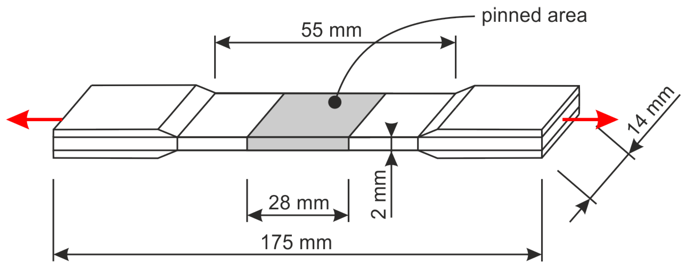
The prepreg material is built up to an UD laminate structure by 15 single layers [ 0 15 ] . With a material-specific single layer thickness of 0.14 mm, the cured laminate has a thickness of approximately 2.1 mm. Using the Ultrasonically Assisted Z-fiber insertion process (UAZ®), described by Partridge and Cartié [15,16], the pins were inserted into the uncured laminate. The insertion of the pins has been done until the notched area is centered to the laminate thickness. Subsequently, the non-inserted parts of the pins were sheared off and the laminate was subjected to the autoclave curing process under vacuum at a temperature of 180 C and a pressure of 600–700 kPa for 180 min. The configuration used for the autoclave curing process corresponds to the set-up described in [36] in order to minimize potential pin misalignment which may be caused by the compaction of the laminate. After the laminate curing were finished, the specimens required for the static tensile tests were cut out. The geometry of the specimens used in the investigations is presented in Figure 2.
The specimens have a length of 175 mm and a width of 14 mm. The pinned region is 28 mm and located in the mid of the specimens. Load application elements with a thickness of 2 mm are bonded to both ends of the specimens to strengthen the ends for clamping in the testing system. The test specimens were loaded using a servo-hydraulic test system (MTS type) with a loading rate of 1 mm/min until fracture. Using an extensometer with a 25 mm gauge length, the force-displacement relationships were determined in the pinned region of the tensile specimen. Five specimens were tested for each notch definition. Additionally, five specimens with unnotched pins and five unpinned specimens were also examined. From the resulting force-displacement relationships, the characteristic values of the composite laminates, Young’s modulus and tensile strength, can be determined.

3. Results and Discussion

3.1. Swelling of Laminate

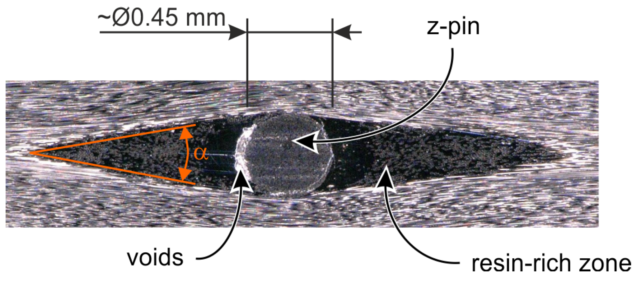
By inserting z-pins into a laminate, additional volumina will be introduced, which increase the thickness in the pinned area, since the volumina in which pins are to be positioned has to evade. The deflection of the laminate fibres results in areas becoming free, in the direct vicinity of the pins, which also contribute to an increase in laminate thickness—swelling of the laminate. Typically, these areas are filled with resin during the curing process (resin-rich zones). As an example, Figure 3 show a cross-sectional view of an unidirectional z-pinned specimens reinforced with notched z-pins with rectangular notches with a notch depth of 25 μ m.
The sectional plane is located in the area of a circumferential notch. The resin-rich areas have a limited dimension, which depends e.g., from the z-pin diameter and the fibre tension of the prepreg material. If these areas cannot be completely filled with the resin during the curing process, voids (e.g., entrapped air) directly at the z-pin can occur, which may act as crack initiators under laminate loading and thus significantly reduce the mechanical properties of the pinned laminate.
Also, the pins work against the compaction during the curing process, so that increased laminate thicknesses can be measured in the pinned areas, compared to unpinned laminates with the same laminate structure [12,16,39]. For all laminates investigated, the resulting laminate thicknesses were measured. The laminate thicknesses of the pinned samples were measured in the areas of the z-pin reinforcement as well as in the unpinned areas. Figure 4 shows the thicknesses of the unpinned and pinned areas of the specimens reinforced with notched pins with constant notch depth of 20 μ m and different notch designs, compared to the values of the specimens with unnotched pins.
As shown in Figure 4, for specimens reinforced with unnotched z-pins a thickness increase of 11.9% can be measured, with 0.5 mm diameter pins at 2% z-pin content. When using notched z-pins, the increase in thickness of the laminate is less, ranging between 8.6% and 9.2%. The reduction can be explained by the lower volumina of the notched z-pins, due to the application of the notches on their surfaces. The difference in the values is caused by the different notch designs, leading to variations in removed material from the pin surface. An exact quantitative evaluation and deducible consistency appears to be only insufficiently achievable with the available data, since a number of variables have an influence on the results (e.g., notch geometry, the quality of the laser ablation, the correct pinning depth and position of the notches to the laminate thickness, and others). However, it can be shown that the thickness increase is lower with notched pins than with unnotched. At first sight, this suggests that the in-plane properties, like the tensile properties, when using notched pins, should be less affected than those of laminates with unnotched pins. Nevertheless, it has to be pointed out that the vendor-specific laminate thickness for the laminate structure used is theoretically 2.1 mm. But all pinned laminates, whether unnotched or notched pins are used, feature a laminate thickness of around 2.3 mm. This suggests that all pins, unnotched and notched, are acting against the compaction of the laminate during the curing process equally. Consequently, the assumption that there is a reduced influence on the in-plane properties, due to a reduction in swelling caused by the notches at the pin surface, is not tenable.

3.2. Tensile Strength

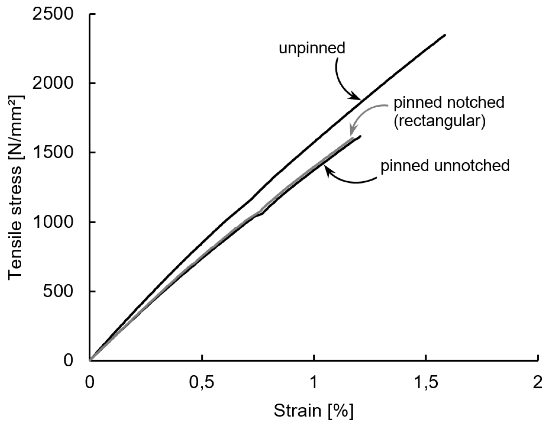
From the measured load-displacement relationships, the typical stress-strain curves can be determined, from which the material-specific parameters, such as tensile strength, can be identified. Figure 5 illustrates representative stress-strain curves of unpinned and pinned laminates, reinforced with unnotched and circumferentially notched z-pins with rectangular notch design (20 μ m notch depth and 100 μ m notch distance).
All measurements show an approximately linear progression until the specimen fails. When maximum load has been achieved, the samples fail suddenly. It can be observed that the tensile strength is significantly reduced by introducing a z-pin reinforcement. Furthermore, the characteristics of the curves of the specimens with a z-pin reinforcement show a lower gradient compared to the specimens without pins, whether z-pins with or without notches are considered.
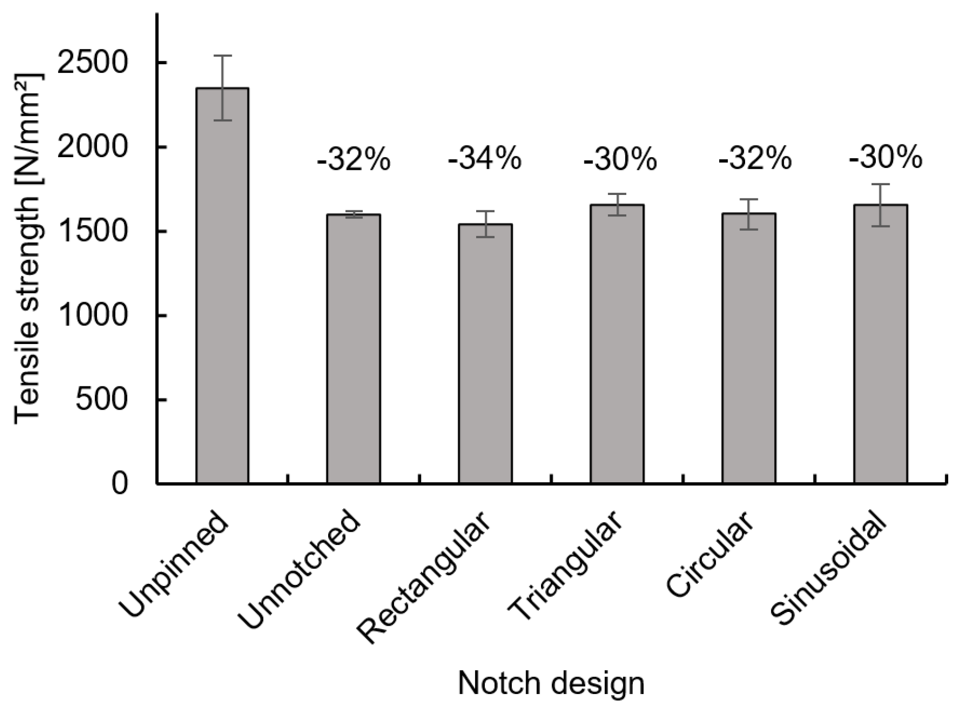
The tensile strength values were determined for all specimens. In Figure 6 the average values of the tensile strength and standard deviation values of unpinned as well as pinned specimens with and without circumferential notches are presented.
In addition to the values of the specimens with unnotched pins, those of the pinned specimens with notched pins with different notch designs with constant notch depth of 20 μ m and notch distance of 100 μ m are also presented. These values are compared to those of the unpinned specimens. For the specimens without a z-pin reinforcement strength values of around 2350 MPa were determined, comparable to findings by Hoffmann et al. [45] and Partridge at al. [46], who have reported strength values of around 2400 MPa and 2490 MPa respectively for unpinned carbon-fibre reinforced prepreg laminates with UD laminate structure. The analysis of the strength values of the samples with unnotched z-pins indicates a reduction of 32%. Hoffmann et al. [45] have demonstrated reductions of the tensile strength of about 43% for an identical z-pin density and diameter as well as laminate structure. Chang et al. [39] have also conducted investigations on UD laminates with a z-pin reinforcement using 0.51 mm pins with a 2% pin density and have found a reduction in tensile strength of approximately 25%. There are numerous additional studies on the impact of a z-pin reinforcement on the tensile properties of composite laminates, however, which cannot be directly compared with the values obtained in this study, since different laminate structures and pinning parameters have been examined [38,46,47]. Generally, the reductions achieved can be attributed to both, the increased fibre waviness and clusters of broken fibres around each pin caused by the insertion process [17,39,45,48]. Additionally, the laminate swelling in the area of the z-pin reinforcement leads to a reduction of the fibre volume content of the laminate, which can also be attributed to the reduction of the in-plane strength values [47]. The formation of cracks in the resin-rich areas, which originate from voids in these areas, also causes a reduction in tensile strength. This effect can be described by the fact that under axial tensile loading the wavy fibres in the direct vicinity of the pins experience a slight degree of straightening when reaching the tensile failure stress. This leads to cracks that are propagating unstable along the resin-rich zones in fibre direction starting at existing voids and causing the splitting of the laminates in load direction. Consequently, changes in the resulting failure pattern of the laminates reinforced with z-pins can be described [39,47]. This way of crack formation when reaching the failure stress can also be observed in the tests carried out in the present study, no matter which pinned samples are observed.
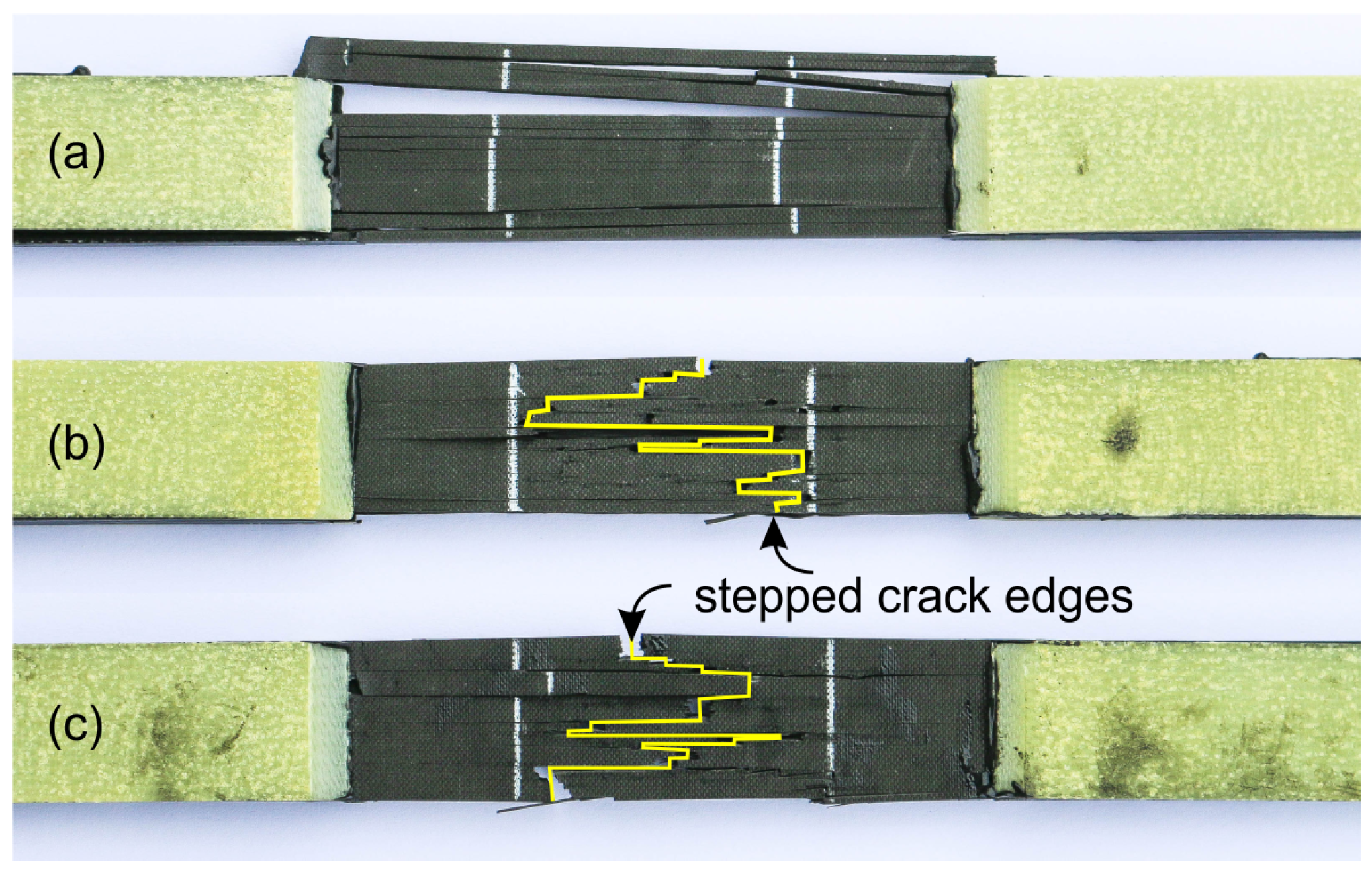
Figure 7 displays three tested samples—unpinned Figure 7a, z-pinned with unnotched pins Figure 7b and z-pinned with rectangular notches at z-pin surface (notch depth 20 μ m, notch distance 100 μ m) Figure 7c.
For the unpinned sample Figure 7a, the typical catastrophic failure can be described that is accompanied by immediate longitudinal crack propagation along the reinforcing fibres splitting the specimen into smaller sub-laminates. Thereby the maximum stress values of these sub-laminates are significantly exceeded, resulting in this immediate failure. In contrast, for pinned specimens with unnotched pins, the fractures of the fibres of the resulting sub-laminates are located directly at the positions of the z-pins, as shown in Figure 7b. This results in a stepped fracture surface between the halves of the specimen. Similar behavior can be observed for specimens with notched pins, as shown in the Figure 7c. This indicates that notching of the z-pin surface is not affecting the fracture behaviour when using 3D reinforcement with notched z-pins.
For the strength values of the specimens with notched z-pins (constant notch depth of 20 μ m and notch distance of 100 μ m) it can be stated that reductions of the tensile failure stress between 30% and 34% can be determined. The findings indicate that there are no significant differences between the various notch designs. The existing mechanisms resulting in the reduction of tensile strength appear identical to those for the unnotched pins. In the direct vicinity of the pins, an increased fiber waviness is evident, but depending on the laminates depth, it varies due to the presence of the notches. During the insertion of the pins, the fibres are displaced from their initial location, resulting in the above-mentioned fibre waviness. During the curing process, the fibres of the laminate are shifted back and pushed into the notches, leading to a reduced waviness in the notched areas of the pins. This should result in a smaller reduction in tensile strength, as the straightening effects described by Chang et al. [39] should be smaller. However, the results do not confirm this assumption when the data are compared with those of the samples with unnotched pins. But it can be assumed that the introduced notches cause stress concentrations at the geometrical cross-overs between notches and webs, under in-plane tensile loading of the laminate. This should have a decreasing effect on the tensile failure stress. From these stress concentrations, which are located directly at the pin even in the resin-rich zones, cracks may be initiated. The cracks can propagate along the UD fibre-reinforcement in the resin-rich zones as the load increases, leading to a reduction in tensile strength. It can be assumed that under tensile loading of the laminate, these two effects showing a characteristic neutralising one another, especially for the investigated notch definition (depth 20 μ m and distance 100 μ m).
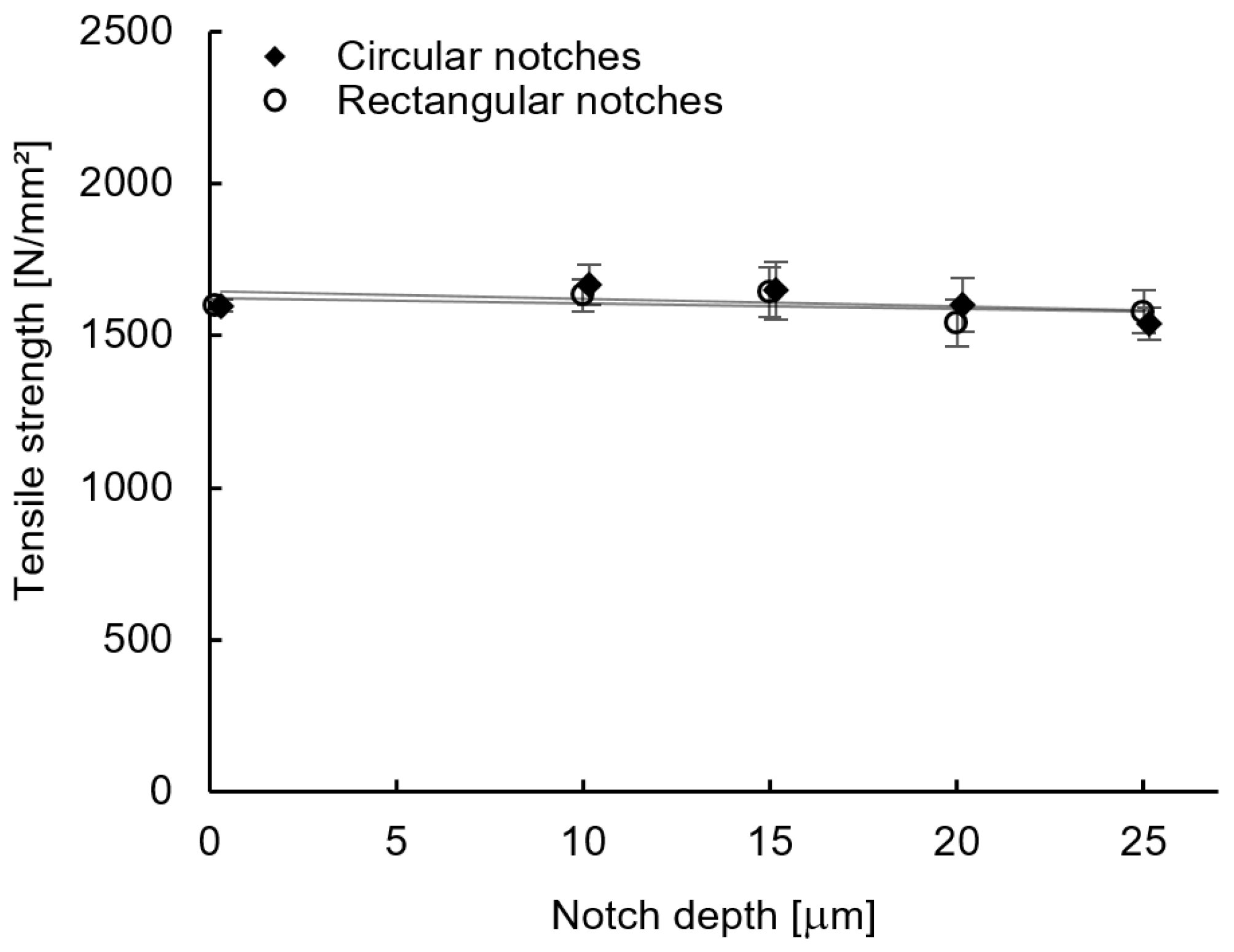
Considering the impact of the notch depth on the resulting maximum tensile stress, as shown in Figure 8 for rectangular and circular notch designs, it can be concluded that no significant effect with increasing notch depth can be observed.
The results indicate no dependency from the notch depth, no matter which notch design is considered. It could have been expected that the higher notch depth and the re-location of the fibres into the notched areas would lead to a reduction of fibre waviness at increasing notch depth and consequently to an increase of tensile strength. Nevertheless, it can be assumed that the fibres in the areas of the webs between the notches still have a high fibre waviness and the failure mechanisms described by Chang et al. [39] are still valid. The staightening effects can still initiate cracks in the resin-rich zones, caused by the waviness of the fibres between the notches. It also has to be pointed out that the combination of several microstructural changes causes reduction of the tensile strength.
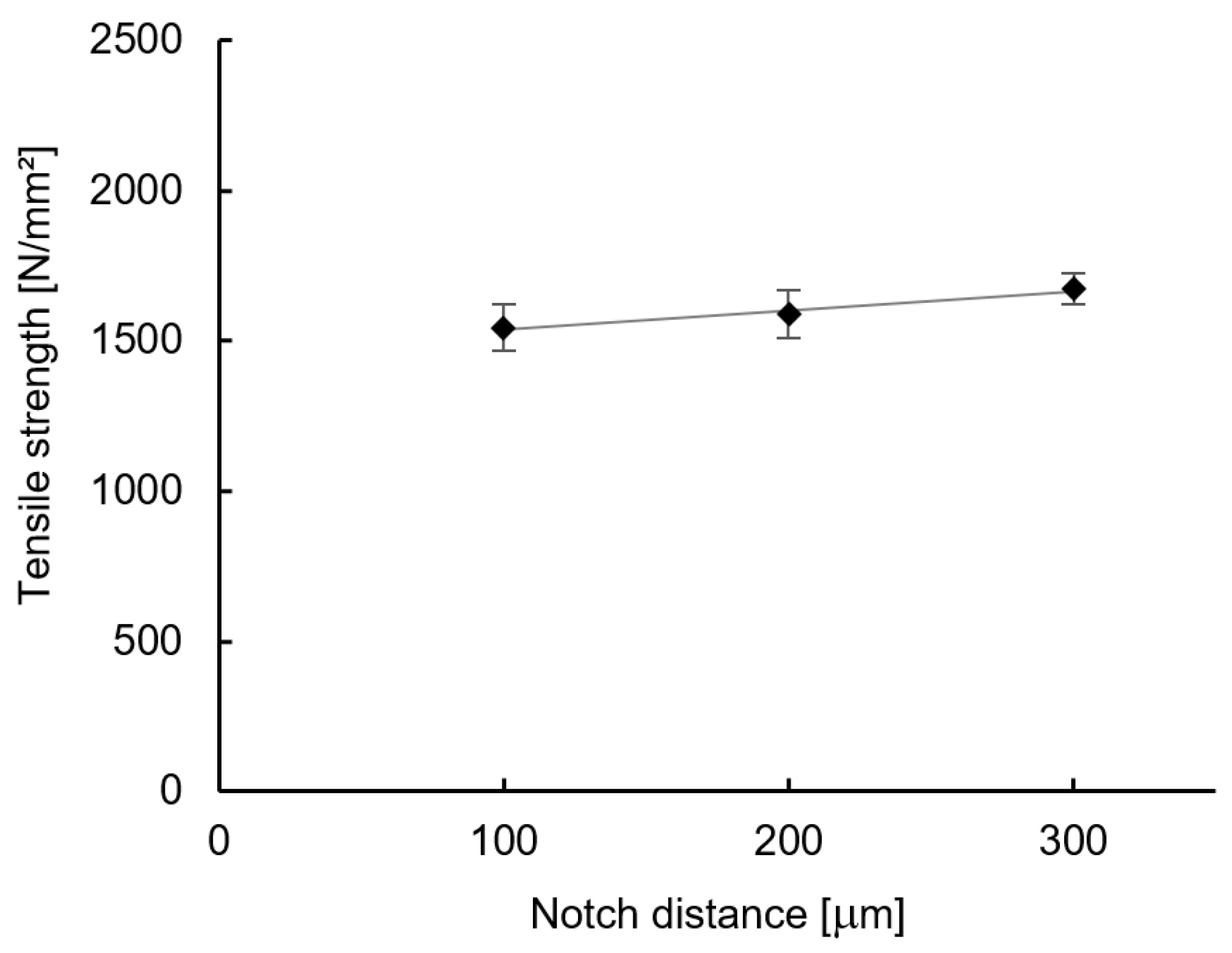
The evaluation of the measured values of the specimens with rectangular notches with a constant notch depth of 20 μ m and varying notch distances is shown in Figure 9.
The results show that a minor increase in tensile strength can be observed with increasing notch distance at constant notch depth. The values found at 200 μ m and 300 μ m notch distance are 4% and 8% higher compared to the reference values for 100 μ m notch distance. It can be demonstrated that the presence of notches at the z-pin surface has a minor impact on the tensile properties, especially the tensile strength, and this effect increases linearly with an increasing notch distance.
As the measured values for the various notch distances do not differ much, a statement on the significance of the increases in strength values with increasing notch distances is difficult. To assess the significance of the presented deviations, the measured strength values were evaluated by an ANOVA-analysis of variance. The results of the analysis indicate that the empirical f-value found exceeds the critical value for a level of significance of 5% and thus a previously defined hypothesis that there are no differences between the measured values can be rejected. Thus, it can be assumed that there is a significant increase of the strength values with increasing notch distance.
It can be concluded that a higher number of notches at the surface of the pins has a negative impact on the resulting in-plane tensile strength. The stress concentrations caused by the notches during in-plane tensile loading are reduced which has a smaller reducing effect on the tensile strength.

3.3. Young’s Modulus

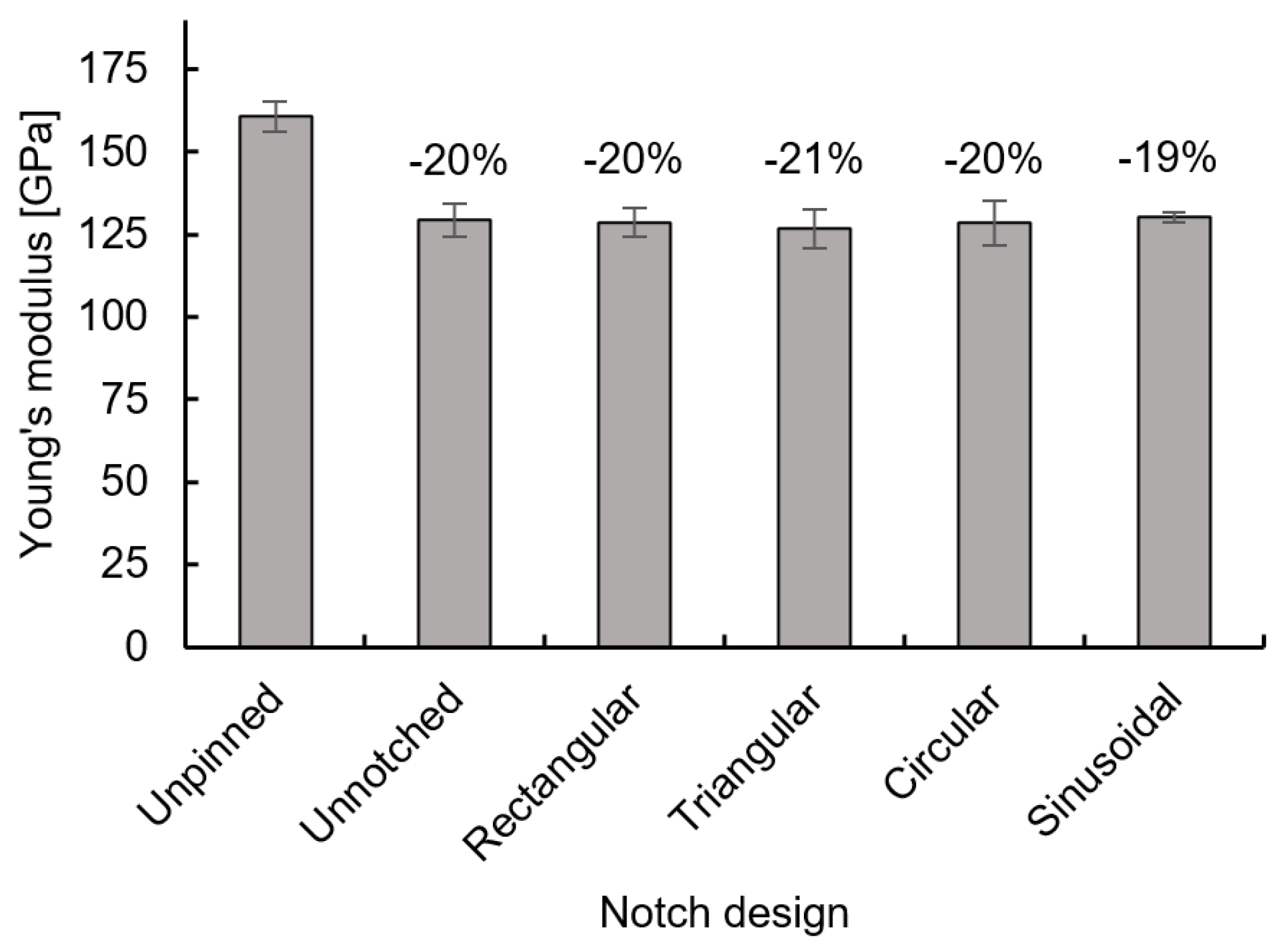
The evaluation of the data on tensile modulus shows that the insertion of a z-pin reinforcement in an unidirectional laminate leads to a significant reduction of tensile modulus, whether notched or unnotched z-pins are used. Figure 10 illustrates the average values of tensile modulus along with the respective standard deviation values of unpinned as well as pinned specimens, unnotched as well as with different notch designs.
The pinned specimens with unnotched z-pins exhibit reductions of the Young’s modulus of 20% compared to the unpinned laminates. This corresponds to the findings of Hoffmann et al. [45], which also measured a decrease of the tensile modulus of 20%, with the same z-pin parameters in unidirectional laminates. In their investigations on unidirectional and quasi-isotropic laminates, Chang et al. [39] also described reductions of the tensile modulus compared to the unpinned laminates. For unidirectional laminates reinforced with big pins (0.51 mm diameter), a reduction of the tensile modulus of 5% for each 1% increase in z-pin density was found. The authors describe that the swelling of the laminate and the resulting reduction of the fibre volume fraction and, more significantly, the misalignment of the laminates fibres in-plane and out-of-plane are responsible for the reductions measured. However, the present study reports higher reductions, suggesting that a higher proportion of the fibres of the laminate were cut and/or deflected in the thickness direction in the investigated laminate material. A higher fraction of misaligned fibres in-plane, compared to the findings of Chang et al. [39], are unlikely, as they are primarily dependent on the diameter of the pins and the laminate structure, which are similar to the parameters investigated.
By comparing the values of the specimens with unnotched pins with those of the notched pins, no significant difference can be identified. The reductions in the Young’s modulus of the specimens with notched pins range from 19% to 21%, compared to the unpinned specimens, as shown in Figure 10. Thus the specimens with notched pins display similar characteristics compared to the specimens with unnotched pins. This indicates that with similar notch definitions (depth and distance) the notch design has no influence on the Young’s modulus. It can also be concluded that when inserting the pins, whether notched or unnotched pins are used, the same microstructural changes responsible for the reduction of the modulus will be induced.
The results of the Young’s modulus in dependency on the notch depth for circular and rectangular notch designs are presented in Figure 11.
In Figure 11 the average values of the Young’s modulus and standard deviation of notched pins as well as unnotched pins are presented. The values indicate that the Young’s modulus has no dependence on the notch depth at a constant notch distance for both circular and rectangular notch designs. These findings indicate that the major component responsible for the reduction of the in-plane tensile modulus results from the out-of-plane fibre misalignment. Chang et al. [39] identified three major drivers for this, the swelling, and the misaligned fibres in-plane and out-of-plane. The swelling, which means the increase in laminate thickness due to the insertion of the pins and the resulting resistance against compaction during the curing process, remains almost identical for all laminates with notched z-pins, as shown by the results obtained (see Figure 4). The in-plane fibre waviness should be partially reduced in the layers of the laminate where the notches are located. As a consequence, this should lead to a higher Young’s modulus, compared to the laminates with unnotched pins. As described previously, the higher reductions of the Young’s modulus of about 20%, versus the reductions reported by Chang, indicate that a higher amount of misaligned fibres in out-of-plane direction can be assumed, caused by the pinning process. This allows to conclude that all pins, with or without notches, are causing identical fibre damages of the laminate in thickness direction. The out-of-plane fibre misalignement arising in the direct vicinity of the pins should thereby represent the decisive factor for the reduction of the tensile modulus. To support this conclusion, further analyses to determine the volume of misaligned fibres in out-of-plane direction are necessary. The aforementioned results of the studies can be additionally supported by the data illustrated in Figure 12.
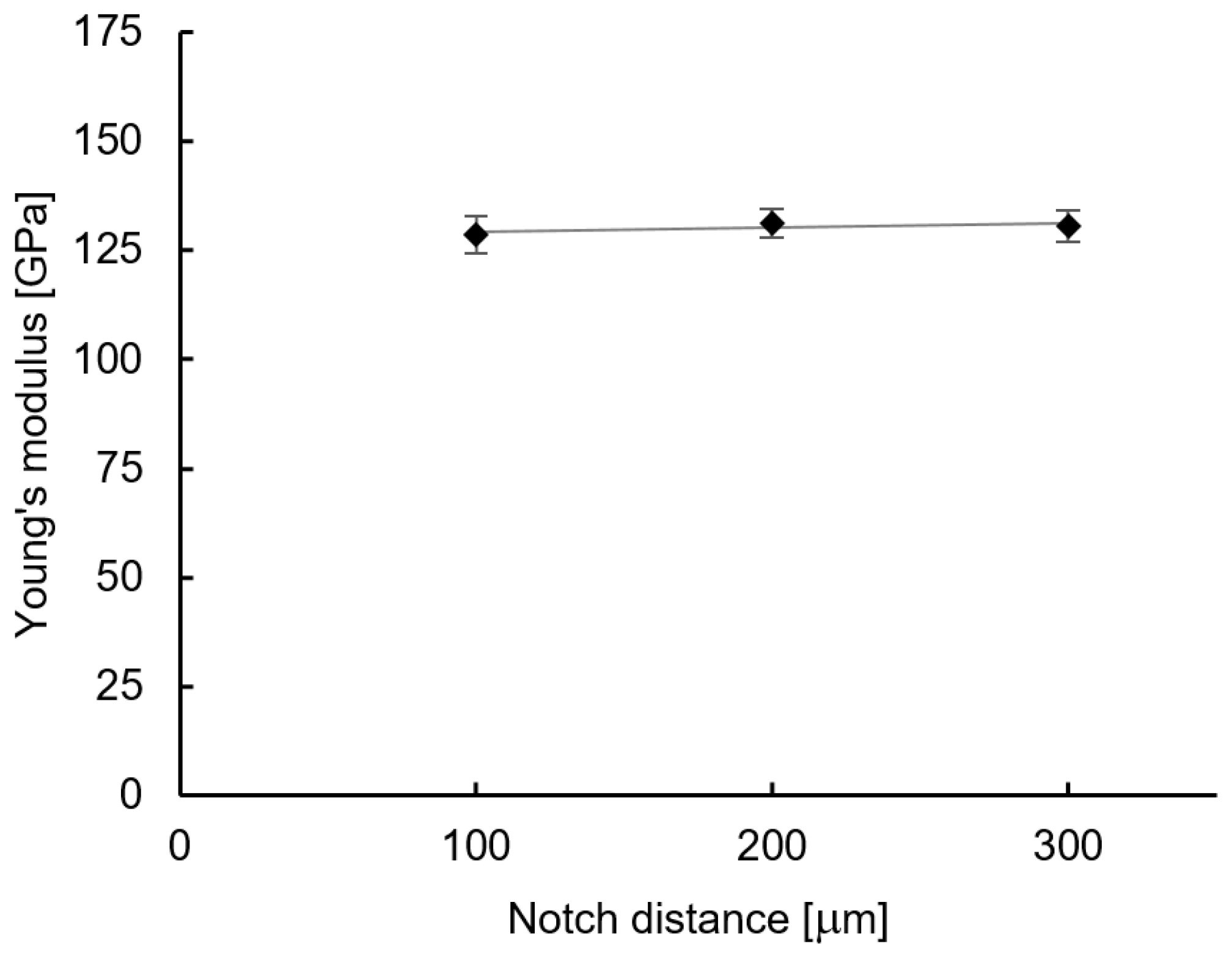
Figure 12 illustrates the dependency of the Young’s modulus from notch distance for rectangular notches with constant notch depth and width. The results indicate that an increasing notch distance and consequently a reduction of the amount of notches at the inserted z-pins has no significant influence on the tensile modulus. This suggests that a change in the proportion of misaligned fibers in-plane of the UD laminate, due to the reduced amount of notches at the pin surface, has no effect on the tensile modulus.

4. Conclusions

Experimental investigations on the influence of circumferentially notched z-pins with different notch designs on the in-plane tensile mechanical properties of z-pin reinforced composite laminates with unidirectional fibre orientation were performed. From the results it can be concluded that the application of circumferential notches at the z-pin surfaces has no substantial influence on the mechanical in-plane properties of a pinned laminate under tensile loading. Considering the tensile strength, the reductions caused by the insertion of the z-pins are identical for all notch designs considered, compared to the samples with unnotched pins. The results obtained with circular and rectangular notch designs indicate that the notch depth has no influence on the tensile strength values of a pinned laminate. Only when investigating the influence of the notch distance at constant notch depth and notch width a smaller lowering of the strength reduction can be determined at higher notch distances. Observing the Young’s modulus in dependency of the notch design, notch depth and notch distance, it can be stated that for all investigated samples no differences to the z-pinned samples with unnotched z-pins can be determined. It can be assumed that the same microstructural changes that are caused by the insertion of the z-pins in the laminate occur with notched and unnotched pins. Based on the results of the investigations performed, it can be concluded that the reduction in tensile strength of both specimens, notched and unnotched, is primarily caused by the fibre straightening effects at the resin-rich zones in the vicinity of the pins as described above. This leads to the formation of cracks at existing voids located in the resin-rich zones, which propagate along the z-pin rows and thus along the reinforcing fibers in an unidirectional laminate and lead to premature failure. However, the Young’s modulus of the pinned laminates is mainly driven by the out-of-plane fibre waviness, which should be approximately identical for the samples with notched and unnotched z-pins. This means that the same values for the Young’s modulus can be determined for specimens with unnotched and notched pins. Nevertheless, it can be challenged that the notches on the z-pin surface have no negative influence on the in-plane properties. Especially the fatigue properties should be influenced by the notching effects caused by the stress concentrations at the transitions between notches and webs resulting in a reduction of the durability of a z-pin reinforced laminate with notched pins. Studies on this topic should be conducted to determine the influence of notches on the fatigue properties of a pinned laminate reinforced with notched z-pins.

Author Contributions

Conceptualization, A.K. and G.S.; methodology, A.K. and G.S.; validation, G.S.; formal analysis, A.K.; investigation, A.K.; resources, G.S.; data curation, A.K.; writing–original draft preparation, A.K.; writing–review and editing, A.K.; visualization, A.K.; supervision, G.S.; project administration, A.K. and G.S.; funding acquisition, G.S. All authors have read and agreed to the published version of the manuscript.

Funding

The studies were conducted as part of a research project (project number: 398803737) funded by the German Science Foundation (DFG). The authors sincerely thank the DFG for this support. Additionally, the authors thank the Cytec Engineered Materials GmbH for supporting the studies by providing the prepreg material used.

Acknowledgments

We acknowledge financial support by Deutsche Forschungsgemeinschaft and Universität Rostock/Universitätsmedizin Rostock within the funding programme Open Access Publishing (project number: 325496636).

Conflicts of Interest

The authors declare no conflict of interest. The funders had no role in the design of the study; in the collection, analyses, or interpretation of data; in the writing of the manuscript, or in the decision to publish the results.

References

  1. Kinloch, A.J.; Young, R.J. Fracture Behaviour of Polymers; Elsevier: London, UK, 1983. [Google Scholar]
  2. Yee, A.F.; Pearson, R.A. Toughening mechanisms in elastomer-modified epoxies. J. Mater. Sci. 1986, 21, 2462–2474. [Google Scholar] [CrossRef] [Green Version]
  3. Mouritz, A.P.; Bannister, M.K.; Falzon, P.J.; Leong, K.H. Review of applications for advanced three-dimensional fibre textile composites. Compos. Part A Appl. Sci. Manuf. 1999, 30, 1445–1461. [Google Scholar] [CrossRef]
  4. Tong, L.; Mouritz, A.P.; Bannister, M.K. 3D Fibre Reinforced Polymer Composites, 1st ed.; Elsevier: Boston, MA, USA, 2002. [Google Scholar]
  5. Leong, K.; Ramakrishna, S.; Huang, Z.; Bibo, G. The potential of knitting for engineering composites—A review. Compos. Part A Appl. Sci. Manuf. 2000, 31, 197–220. [Google Scholar] [CrossRef]
  6. Mungalov, A. Complex shape 3-D braided composite-preforms: Structural shapes for marine and aerospace. SAMPE J. 2004, 40, 7–21. [Google Scholar]
  7. Kyosev, Y. Advances in Braiding Technology: Specialized Techniques and Applications; Woodhead Publishing Series in Textiles; Elsevier Science: Amsterdam, The Netherlands, 2016. [Google Scholar]
  8. Weimer, C.; Preller, T.; Mitschang, P.; Drechsler, K. Approach to net-shape preforming using textile technologies. Part I: Edges. Compos. Part A Appl. Sci. Manuf. 2000, 31, 1261–1268. [Google Scholar] [CrossRef]
  9. Dransfield, K.; Baillie, C.; Mai, Y.W. Improving the delamination resistance of CFRP by stitching—A review. Compos. Sci. Technol. 1994, 50, 305–317. [Google Scholar] [CrossRef]
  10. Dell’Anno, G.; Cartié, D.D.R.; Partridge, I.K.; Rezai, A. Exploring mechanical property balance in tufted carbon fabric/epoxy composites. Compos. Part A Appl. Sci. Manuf. 2007, 38, 2366–2373. [Google Scholar] [CrossRef] [Green Version]
  11. Kusaka, T.; Watanabe, K.; Hojo, M.; Fukuoka, T.; Ishibashi, M. Fracture behaviour and toughening mechanism in Zanchor reinforced composites under mode I loading. Eng. Fract. Mech. 2012, 96, 433–446. [Google Scholar] [CrossRef]
  12. Mouritz, A.P. Review of z-pinned composite laminates. Compos. Part A Appl. Sci. Manuf. 2007, 38, 2383–2397. [Google Scholar] [CrossRef]
  13. Hoffmann, J.; Scharr, G. Pull-out performance of rectangular z-pins in hot-cured carbon fiber reinforced laminates. Compos. Struct. 2018, 186, 62–67. [Google Scholar] [CrossRef]
  14. Knaupp, M.; Baudach, F.; Franck, J.; Scharr, G. Mode I and pull-out tests of composite laminates reinforced with rectangular z-pins. J. Compos. Mater. 2014, 48, 2925–2932. [Google Scholar] [CrossRef]
  15. Partridge, I.K.; Cartié, D.D.R. Delamination resistant laminates by Z-Fiber® pinning: Part I manufacture and fracture performance. Compos. Part A Appl. Sci. Manuf. 2005, 36, 55–64. [Google Scholar] [CrossRef]
  16. Partridge, I.K.; Cartié, D.D.R.; Bonnington, T. Manufacture aNd Performance of Z-Pinned Composites. In Advanced Polymeric Materials: Structure Property Relationships; Shonaike, G.O., Advani, S.G., Eds.; CRC Press: Boca Raton, FL, USA, 2003; pp. 114–153. [Google Scholar]
  17. Freitas, G.; Magee, C.; Dardzinski, P.; Fusco, T. Fiber insertion process for improved damage tolerance in aircraft laminates. J. Adv. Mater. 1994, 25, 36–43. [Google Scholar]
  18. Liu, H.Y.; Takeda, N.; Yan, W.; Hamada, H.; Gu, B.; Ogihara, S.; Dai, S.C.; Nakai, A.; Mai, Y.W. Z-pinning reinforcement and its bridging law. In Proceedings of the Asian-Australian Conference on Composite Materials, Tokyo, Japan, 18–21 November 2003; pp. 389–393. [Google Scholar]
  19. Cartié, D.D.R.; Troulis, M.; Partridge, I.K. Delamination of Z-pinned carbon fibre reinforced laminates. Compos. Sci. Technol. 2006, 66, 855–861. [Google Scholar] [CrossRef] [Green Version]
  20. Cartié, D.D.R.; Laffaille, J.M.; Partridge, I.K.; Brunner, A.J. Fatigue delamination behaviour of unidirectional carbon fibre/epoxy laminates reinforced by Z-Fiber® pinning. Eng. Fract. Mech. 2009, 76, 2834–2845. [Google Scholar] [CrossRef] [Green Version]
  21. Hoffmann, J.; Scharr, G. Mode I delamination fatigue resistance of unidirectional and quasi-isotropic composite laminates reinforced with rectangular z-pins. Compos. Part A Appl. Sci. Manuf. 2018, 115, 228–235. [Google Scholar] [CrossRef]
  22. Yan, W.; Liu, H.Y.; Mai, Y.W. Mode II delamination toughness of z-pinned laminates. Compos. Sci. Technol. 2004, 64, 1937–1945. [Google Scholar] [CrossRef] [Green Version]
  23. Allegri, G.; Yasaee, M.; Partridge, I.K.; Hallett, S.R. A novel model of delamination bridging via Z-pins in composite laminates. Int. J. Solids Struct. 2014, 51, 3314–3332. [Google Scholar] [CrossRef] [Green Version]
  24. Cartié, D.D.R. Effect of z-Fibres™ on the Delamination Behaviour of Carbon-Fibre/epoxy Laminates. Ph.D. Thesis, Cranfield University, Cranfield, UK, 2000. [Google Scholar]
  25. Zhang, B.; Allegri, G.; Yasaee, M.; Hallett, S.R. Micro-mechanical finite element analysis of Z-pins under mixed-mode loading. Compos. Part A Appl. Sci. Manuf. 2015, 78, 424–435. [Google Scholar] [CrossRef]
  26. Rugg, K.L.; Cox, B.N.; Massabo, R. Mixed mode delamination of polymer composite laminates reinforced through the thickness by z-fibers. Compos. Part A Appl. Sci. Manuf. 2002, 33, 177–190. [Google Scholar] [CrossRef]
  27. Zhang, X.; Hounslow, L.; Grassi, M. Improvement of low-velocity impact and compression-after-impact performance by z-fibre pinning. Compos. Sci. Technol. 2006, 66, 2785–2794. [Google Scholar] [CrossRef] [Green Version]
  28. Knaupp, M.; Baudach, F.; Franck, J.; Scharr, G. Impact and post-impact properties of cfrp laminates reinforced with rectangular z-pins. Compos. Sci. Technol. 2013, 87, 218–223. [Google Scholar] [CrossRef]
  29. Francesconi, L.; Aymerich, F. Effect of Z-pinning on the impact resistance of composite laminates with different layups. Compos. Part A Appl. Sci. Manuf. 2018, 114, 136–148. [Google Scholar] [CrossRef]
  30. Francesconi, L.; Aymerich, F. Impact and Post-impact Behavior of Composite Laminates Reinforced by Z-Pins. In Mechanics of Composite, Hybrid and Multifunctional Materials; Springer: Berlin/Heidelberg, Germany, 2019; Volume 5, pp. 159–167. [Google Scholar]
  31. Dai, S.C.; Yan, W.; Liu, H.Y.; Mai, Y.W. Experimental study on z-pin bridging law by pullout test. Compos. Sci. Technol. 2004, 64, 2451–2457. [Google Scholar] [CrossRef] [Green Version]
  32. Cartié, D.D.R.; Cox, B.N.; Fleck, N.A. Mechanisms of crack bridging by composite and metallic rods. Compos. Part A Appl. Sci. Manuf. 2004, 35, 1325–1336. [Google Scholar] [CrossRef] [Green Version]
  33. Vazquez, J.T.; Castanié, B.; Barrau, J.J.; Swiergiel, N. Multi-level analysis of low-cost Z-pinned composite joints: Part 1: Single Z-pin behaviour. Compos. Part A Appl. Sci. Manuf. 2011, 42, 2070–2081. [Google Scholar] [CrossRef]
  34. Knopp, A.; Scharr, G. Effect of z-pin surface treatment on delamination and debonding properties of z-pinned composite laminates. J. Mater. Sci. 2014, 49, 1674–1683. [Google Scholar] [CrossRef]
  35. Knopp, A.; Scharr, G. X-ray photo-electron spectroscopic studies of cryogenic and plasma surface-treated z-pins. J. Compos. Mater. 2017, 51, 1155–1166. [Google Scholar] [CrossRef]
  36. Knopp, A.; Scharr, G. Experimental Investigations on the Influence of Notch Definition on the Pullout Performance of Circumferentially Notched z-pins. Compos. Struct. 2020, in press. [Google Scholar] [CrossRef]
  37. Knopp, A.; Scharr, G. Experimental Investigation on the Influence of Different Notch Designs on the Pullout Performance of Circumferentially Notched Z-Pins. J. Compos. Sci. 2020, 4, 67. [Google Scholar] [CrossRef]
  38. Steeves, C.A.; Fleck, N.A. In-plane properties of composite laminates with through-thickness pin reinforcement. Int. J. Solids Struct. 2006, 43, 3197–3212. [Google Scholar] [CrossRef] [Green Version]
  39. Chang, P.; Mouritz, A.P.; Cox, B.N. Properties and failure mechanisms of z-pinned laminates in monotonic and cyclic tension. Compos. Part A Appl. Sci. Manuf. 2006, 37, 1501–1513. [Google Scholar] [CrossRef]
  40. Mouritz, A. Compression properties of z-pinned composite laminates. Compos. Sci. Technol. 2007, 67, 3110–3120. [Google Scholar] [CrossRef]
  41. Steeves, C.A.; Fleck, N.A. In-plane properties of CFRP laminates containing through-thickness reinforcing rods (Z-pins). In Proceedings of the 12th International Conference on Composite Materials (ICCM-12), Paris, France, 5–9 July 1999. [Google Scholar]
  42. Chang, P.; Mouritz, A.; Cox, B. Flexural properties of z-pinned laminates. Compos. Part A Appl. Sci. Manuf. 2007, 38, 244–251. [Google Scholar] [CrossRef]
  43. Knopp, A.; Düsterhöft, C.; Reichel, M.; Scharr, G. Flexural properties of z-pinned composite laminates in seawater environment. J. Mater. Sci. 2014, 49, 8343–8354. [Google Scholar] [CrossRef]
  44. Hoffmann, J.; Sabban, J.; Scharr, G. Pullout performance of circumferentially notched z-pins in carbon fiber reinforced laminates. Compos. Part A Appl. Sci. Manuf. 2018, 110, 197–202. [Google Scholar] [CrossRef]
  45. Hoffmann, J.; Scharr, G. Mechanical properties of composite laminates reinforced with rectangular z-pins in monotonic and cyclic tension. Compos. Part A Appl. Sci. Manuf. 2018, 109, 163–170. [Google Scholar] [CrossRef]
  46. Partridge, I.K.; Cartié, D.D.R.; Troulis, M.; Grassi, M.; Zhang, X. Evaluating the mechanical effectiveness of z-pinning. In Proceedings of the 35th International SAMPE Technical Conference, Dayton, OH, USA, 28 September–2 October 2003. [Google Scholar]
  47. Dan, M.; Yong, L.; Tao, S.; Lin, F.; Peng, W.; Jun, X. Tensile properties of Z-pins reinforced laminates. Polym. Polym. Compos. 2011, 19, 251–258. [Google Scholar] [CrossRef]
  48. Stringer, L.G.; Hiley, M.J. Through-thickness Reinforcement of Composites: Z-pinning, Stitching, and 3D weaving. In Proceedings of the 14th International Conference on Composite Materials, San Diego, CA, USA, 14–18 July 2003. [Google Scholar]
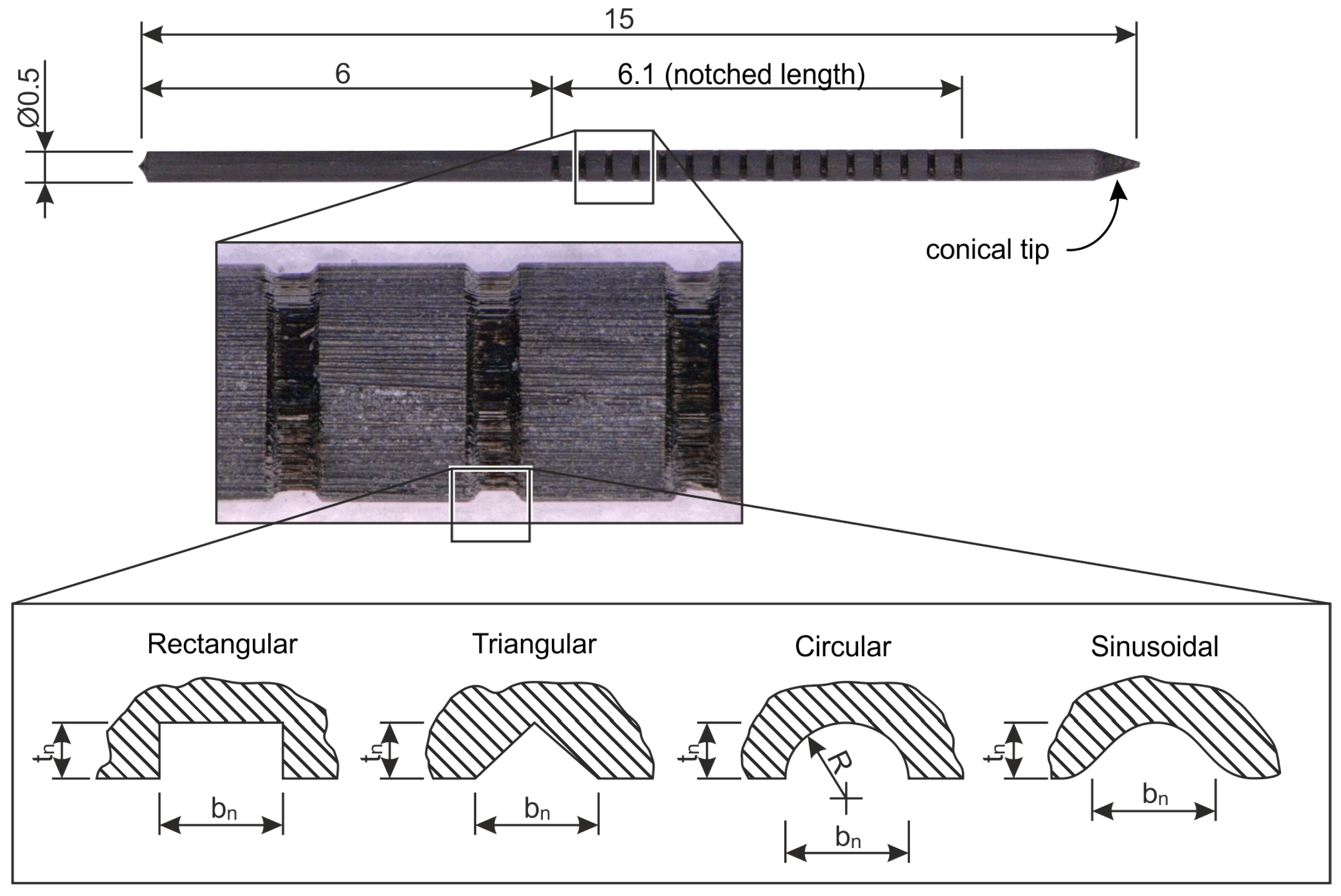
Figure 1. Definition of the z-pins with notched region at the surface as well as the different notch designs investigated.
Jcs 04 00078 g001
Figure 2. Specimen geometry, position of pinned region as well as test set-up for the determination of the tensile properties of unpinned and z-pinned UD carbon-fiber reinforced composite laminates.
Jcs 04 00078 g002
Figure 3. Cross-sectional view of an unidirectional z-pinned laminate reinforced with circumferentially notched z-pins with a rectangular notch design and a notch depth of 25 μ m. The sectional plane is located in the area of a notch.
Jcs 04 00078 g003
Figure 4. Average values and standard deviation values of laminate thicknesses in the pinned and unpinned areas of the z-pin reinforced specimens with unnotched and notched z-pins with constant notch depth of 20 μ m. The percentage increase of laminate thicknesses of z-pinned areas compared to the areas without pins is also shown.
Jcs 04 00078 g004
Figure 5. Representative load-displacement curves for tensile tests of unpinned unidirectional laminates as well as z-pin reinforced laminates with unnotched pins and notched pins with rectangular notch design with a notch depth of 20 μ m and notch distance of 100 μ m.
Jcs 04 00078 g005
Figure 6. Tensile strength values and standard deviation values of unidirectional carbon-fibre reinforced composite laminates reinforced with unnotched z-pins as well as with circumferentially notched z-pins with different notch designs at constant notch depth of 20 μ m and notch distance of 100 μ m, in comparison to unpinned laminate.
Jcs 04 00078 g006
Figure 7. Tensile test specimens after testing (a) unpinned; (b) pinned with unnotched z-pins; (c) pinned with notched z-pins (notch depth 20 μ m, notch distance 100 μ m).
Jcs 04 00078 g007
Figure 8. Average values of the tensile strength and standard deviation for z-pinned reinforced unidirectional carbon-fibre/epoxy composites with notched z-pins, circumferentially notched with rectangular and circular notches with constant notch width and distance of 100 μ m each, depending on the notch depth; the values for a notch depth of 0 μ m correspond to the values for unnotched z-pins.
Jcs 04 00078 g008
Figure 9. Average values of tensile strength and standard deviation for z-pinned unidirectional carbon/epoxy composites reinforced with circumferentially notched z-pins with rectangular notch design with constant notch depth of 20 μ m in dependency of the notch distances.
Jcs 04 00078 g009
Figure 10. Average values of tensile modulus and standard deviation of unidirectional carbon-fibre/ epoxy laminates reinforced with unnotched z-pins as well as with circumferentially notched z-pins with different notch designs at constant notch depth of 20 μ m and notch distance of 100 μ m, in relation to the unpinned laminate.
Jcs 04 00078 g010
Figure 11. Tensile modulus and standard deviation values for z-pinned unidirectional carbon epoxy composite laminates reinforced with notched z-pins—circumferentially notched with rectangular and circular notches with constant notch width and distance of 100 μ m each—depending on the notch depth; the values for a notch depth of 0 μ m correspond to the values for unnotched z-pins.
Jcs 04 00078 g011
Figure 12. Average values of Young’s modulus and standard deviation for z-pinned reinforced unidirectional carbon/epoxy composites with notched z-pins, circumferentially notched with rectangular notch design with constant notch width of 100 μ m and notch depth of 20 μ m, at different notch distances.
Jcs 04 00078 g012
Table 1. Details of investigated notch designs and number of specimens tested.
Notch Definition
DesignDepth tn [ μ m]Width bn [ μ m]Distance dn [ μ m]No. of [Pcs]
Unpinned---5
Unnotched---5
Rectangular101001005
Rectangular151001005
Rectangular201001005
Rectangular251001005
Rectangular201002005
Rectangular201003005
Triangular201001005
Sinusoidal201001005
Circular201001005
Circular101001005
Circular151001005
Circular251001005