Review

The Use of Composite Materials in 3D Printing

Department of Civil Engineering and Architecture and UdR-Catania Consorzio INSTM, University of Catania, Viale Andrea Doria 6, 95125 Catania, Italy
J. Compos. Sci. 2020, 4(2), 42; https://doi.org/10.3390/jcs4020042
Submission received: 1 April 2020 / Revised: 14 April 2020 / Accepted: 20 April 2020 / Published: 22 April 2020

Abstract

:
Nowadays, all production, from the smallest ones to large companies, and research activities are affected by the use of 3D printing technology. The major limitation, in order to cover as many fields of application as possible, is represented by the set of 3D printable materials and their limited spectrum of physico-chemical properties. To expand this spectrum and employ the 3D-printed objects in areas such as biomedical, mechanical, electronical and so on, the introduction of fibers or particles in a polymer matrix has been widely studied and applied. In this review, all those studies that proposed modified polymer presenting advantages associated with rapid prototyping are reported.

1. Introduction

In recent years, there has been rapid development in 3D printing technology, and all the chemical and materials engineers who deal with the design and production of manufacts, are contributing to the development of this technology. This review aims to mark the state of the art in 3D printing technology with particular reference to the use of composite materials for fused deposition modeling (FDM).
The literature dates back to 1984, with the development of stereolithography and thus the advent of commercial additive manufacturing (AM), the beginning of the third Industrial Revolution [1,2]. The term stereolithography was coined by Charles (“Chuck”) Hull in 1984 when he applied for a patent on the process [3]. In 1986, after the discovery of stereolithography, that is a technique that allows for the creation of single three-dimensional objects from successive solidified layers of ultraviolet light sensitive resin, starting directly from digital data processed by a Computer-Aided Drafting (CAD) software, Chuck Hull founded the 3D Systems, which was the first 3D printing company in the world. In 1988, Scott Crump discovered the fused deposition modeling (FDM) and founded Stratasys, the actual world’s leading 3D printing company [4]. The single step operation, characterizing FDM, allows for the rapid creation of 3D manufacts from CAD designs, thus reducing the cycle time of production. In FDM, molten material is forced out of the print head’s nozzle and is deposited on the growing workpiece. The head is moved, under computer control, in two dimensions to deposit one horizontal plane at a time, before moving slightly upwards to begin a new slice [5]. In 1991, Helisys markets the first Laminated Object Manufacturing (LOM). The process involves the realization of the object using sheets of paper cut and glued downstairs [6]. Just a year later, the selective laser sintering (SLS) process was developed at the University of Texas [7] and was commercialized by DTM Corporation, a start-up that was then acquired by 3D Systems. The SLS technique uses a laser as the power source to sinter powdered material. In 2005, at the University of Bath, inspired by an idea of Adrian Bowyer, the Replicating Rapid Prototyper Project took shape, becoming famous with the acronym RepRap. The initiative of the British researcher, developed under open source licenses, aimed at designing a 3D printer that produces itself the majority of its own components. In 2010, the world’s first 3D-printed prototype car, Urbee, was released [8]. In the meantime, during the Tissue Engineering and Regenerative Medicine International Society (TERMIS) meeting in Orlando, Florida, Organovo Inc, a regenerative medicine company focused on bioprinting technology, announced the release of the first fully bioprinted blood vessels and probably it started the fourth industrial revolution [9]. Today, we can affirm that there are no limits to the possibilities offered by this technology, whatever you might think, you can print it. At this point, the reader is probably led to think “Ok, wonderful technology but what is its cost?”. Today, the market offers 3D printers for all budgets, starting from professional printers (the cost of which ranges from 100,000 to 130,000 euros with three material option printing, whilst each additional one about 13,000 euros) to smaller printers (ranging from 2000 to 20,000 euros). Moreover, each of us can buy a printer with a couple of hundred euros, in any e-commerce shop, and toys manufacturers have launched in the market, at a very competitive prices, a toy printer. A toy that produces toys, which closes the circle with the belief of Adrian Bowyer of the University of Bath, a 3D printer that produces itself. This review does not aim to illustrate and deepen the various 3D printing technique, in literature many papers dealing with this are available [10,11,12,13], but rather focuses the reader’s attention on the materials to be printed. All of you have dealt with a classic printer and you know that the real business is not the printer but the cartridges for printing, it is not just an economic issue but it regards the printing quality. You can have the best printer in the world but the quality of the product depends on the material you use to print, and if you consider that today you can print in 3D pieces for structural or biomedical applications it is easily understandable that printing quality is of vital importance. The well-recognized material of the last century was the polymer, due to its ability to provide economic and structural benefits, but from the perspective of 3D-printing, the lack of mechanical strength and functionality is a big challenge for their wide applications [12]. Combining various materials in order to overcome these problems is the right road toward mechanical, thermal and durability improvement, so that the composites can be considered the reference materials for the twenty-first century [14]. The next frontier is to design new composite materials compatible with the available printers and able to satisfy the needs for special applications.

2. Fibers Reinforced Composites

Most of the materials commonly used in FDM, such as thermoplastic polyester-based elastomer, poly(acrylonitrile–butadiene–styrene) (ABS), polycarbonate (PC), and polyphenylsulfone (PPSU), do not possess the strength to produce fully functional parts, thus restricting this technique as well as other rapid prototyping ones [15]. The development of a fiber-reinforced polymer matrix is a way to overcome this limitation and extend the application range of FDM and related techniques.

2.1. ABS Composites

ABS, together with nylon copolymer, was one of the first materials commercially available for a FDM rapid prototyping system but, already from its first applications, there was interest in developing composites able to be used prototypes fabrication with higher mechanical properties giving the parts greater functionality.
In 1998, Gray and coworkers employed a dual extrusion process to blend thermotropic liquid crystalline polymers (TLCP) and Polypropylene (PP) forming a self-reinforced composite fiber to increase their mechanical behavior [16]. A random copolyester based on hydroxobenzoic acid (73% mole) and 2-hydroxy-6-naphthoic acid (27% mole) (Vectra A) blended with polypropylene (PP) monofilaments were used for obtaining plaques via FDM, then the effects of fabrication temperature on the tensile properties of the final part were examined. They observed an increase in the tensile modulus of Vectra A/PP (40/60 wt%) composite plaques of about 100% in respect to those of ABS prototypes and of 150% to those of pure PP, thus concluding that the mechanical properties of the final part can be engineered to match the requirements of the proposed prototype by adjusting the lay-down pattern.
Zhong et al. carried out a series of experiments to verify the processability of short-glass-fiber-reinforced ABS composites for use as feedstock filaments in FDM [17]. The raw materials were mixed in a twin-screw extruder to obtain small pellets, then fed into the single screw extruder for obtaining filament form.
The drawn filament (with a diameter ranging in 1.75–1.90 mm) was wound up onto a drum and then fed into a multi-functional RP&M Machine (MEM-250) operating in the FDM mode. The MEM-250 nozzle moved, by PC controlling, along a square route to form two sizes of square boxes (Figure 1), the first of which had 50 × 50 × 100 mm dimensions and the second had 100 × 100 × 90 mm. The nozzle was maintained at 250 °C, whilst the build chamber was kept at 60 °C. Two types of sample were machined from either frame, as indicated in Figure 1. The sample length direction was parallel to that of the nozzle movement one (parallel to the X–Y plane or layer plane) for the Type 1 sample and was perpendicular for the Type 2 sample (sample length is in the Z- or thickness direction). Both the typology of samples is 90 × 20 mm with the thickness being equal to the diameter of the feedstock filament. They found a significant improvement in the strength of glass-fiber-reinforced ABS filaments at the expense of reduced flexibility and handleability, thus resulting to work well with a FDM machine.
Shofner et al., by using a Banbury mixing, compression molding, and extrusion, prepared composite material consisting of aligned vapor-grown carbon fibers (VGCFs) and ABS, for use in FDM [15]. They observed a high dispersion and distribution of the fibers in the polymeric matrix, as well as low porosity, thus leading to considerable mechanical property improvements. The tensile strength and modulus of the composite showed an average increase of 39% and 60%, respectively, over the unfilled ABS. Dynamic mechanical analysis (DMA) showed a stiffness increase of 68%. In particular, Shofner and his colleagues observed that the improvement in the tensile tests were affected by the build parameters of the sample and the degree of intralayer and interlayer fusion. The presence of the fibers provided additional stiffness and strength but did not affect, appreciably, the viscous response of the polymer. They justified these results, affirming that the VGCFs change the fracture mode of the ABS polymer from ductile to brittle due to a not ideal bonding between part layers and at the fiber/matrix interface. This highlighted the need for FDM process optimization and further fiber treatment to promote a better fiber/matrix adhesion for increasing the ductility of the composite material and led to a larger mechanical property increase.
Ozcan and coworkers come back to consider short fiber-reinforced ABS composite, and although they observed a relatively high porosity, the tensile strength and modulus of the studied composites were comparable [18]. They justified this finding with the changes in fiber orientation, dispersion and void formation. In particular, they observed an increase in voids formation inside the FDM-printed beads and a decrease between the beads, with increasing fiber content. By approaching perfect alignment with the beads, they printed samples having high fiber orientation in the printing direction, concluding that composites with highly dispersed and highly oriented carbon fibers can be printed by the FDM process, as illustrated in Figure 2.
They recorded that both tensile strength and modulus increased dramatically, reaching a specific strength (52.9 kN m/kg) higher than Aluminum 6061-0 (45.9 kN m/kg). Moreover, in this study, the authors concluded that minimizing pore formation during printing and fiber breakage during compounding, as well as improving interfacial adhesion between fibers and matrix via surface modification, appears to be the key point to reach full potential for FDM.
Cong et al. studied the influence of different content and length of carbon fibers in thermoplastic matrix carbon-fiber-reinforced plastic (CFRP) composites for improving the mechanical properties of FDM-fabricated parts [19]. To meet this purpose, they used ABS pellets and carbon fiber powders, having two different average lengths, 150 and 100 mm, respectively. The pellets and carbon fiber powders were mixed in a blender with different carbon fiber contents (3, 5, 7.5, 10 and 15 wt%) and then extruded twice to make them with a high bulk density, which led to more consistent flow rates and fusion on each layer. In comparison with the virgin specimen, they found that the presence of carbon fibers increases tensile strength and Young’s modulus, but decreases toughness, yield strength, and ductility. In particular, they found the largest increase in Young’s modulus (30.5%) by using specimen with 7.5 wt% carbon fiber content. As regards the fiber’s length, the composite specimen with 150 mm carbon fiber had larger tensile strength and Young’s modulus than that with 100 mm carbon fiber. Finally, they observed an increase in porosity when 10 wt% of carbon fiber was added to the polymer (Figure 3), thus leading the smallest mean values of tensile strength, toughness, yield strength, and ductility.
Yang and coworkers focused their attention on avoiding the use of molds, because of high cost, and improving the fibers’ alignment to make manufacturing the boundedness of complex constructions in FDM easier. Aiming to perform a low-cost rapid fabrication of complex composite shapes, they designed a novel 3D printing methodology, described as a transient printing process, consisting of the thermoplastic polymer melting, the continuous fiber hot-dipping and the composite materials mixed extruding [20]. They tested 10 wt.% continuous carbon fiber (CCF)/acrylonitrile-butadiene-styrene (ABS) specimens by using an equipment including a novel extrusion head and control system. They observed a flexural strength and tensile strength improvement in respect to pristine ABS (127), and a very close value to the one of CCF/ABS (147 MPa) obtained by injection molding using the same fiber content. The weak meso/micro/nano scale interfaces in the printed parts of the composite led to a low interlaminar shear strength (2.81 MPa) and interface performance.
Since the residual stresses induced in the layer-by-layer fabrication process of additively manufactured parts have significant impact on their mechanical properties and dimensional accuracy, Chou et al. characterized the residual stress and deformation in short carbon-fiber-reinforced ABS [21]. The fiber content was about 15 wt% and lengths ranging from 5 to 465 mm, with a number-based average of 71.5 mm. In the fabrication process, three raster angles of 0°, ±45° and 0°/90° as well as three printing speeds of 40, 60 and 80 mm/s were selected to build the specimen in the horizontal plane (X–Y). They observed a great influence of raster angle (Figure 4), printing rate, and material typology on the specimen shrinkage and porosity content. They observed an increase in porosity, residual stress, and shrinkage because of the high printing rate and specimen thermal treatment, attributing to the raster angle the main influence on shrinkage and porosity. Thus, they concluded that the composite printing wires, based on short carbon fiber, in ABS significantly reduced the shrinkage and deformation, but led to a porosity increase.

2.2. Epoxy Resin Composites

Mahajan and Cormier, given that the addition of carbon fiber to a polymer matrix greatly enhances mechanical strength, electrical conductivity, and thermal conductivity, demonstrated that these properties are significantly influenced by the degree of fiber alignment (or lack thereof) [23]. Starting from an epoxy resin, the carbon fibers have been aligned during a micro-extrusion process. The carbon fibers and epoxy resin were mixed before extruding, and composite inks were loaded into a 3 cc plastic syringe barrels. The diameter and the average length of the carbon fibers were 7.2 and 100 μm, respectively, and the authors highlighted that the carbon fiber’s length is a decisive factor as it affects fiber alignment as well as the mechanical properties. They observed, for the printed part with carbon fibers aligned along and perpendicular to tensile axis, a 44.12% increase in ultimate tensile stress, and a 42.67% increase in sample modulus with carbon fibers aligned along the tensile axis. The strength of the composite reaches its maximum potential when the length of carbon fibers meets the critical fiber length. The two researchers conclude their study by suggesting to try different ways to extrude longer fibers that satisfy the critical fiber length without clogging the nozzle.
A significant advance in the scientific and technological development of micro-extrusion 3D printing techniques for the AM of high performance, high aspect ratio carbon-fiber filled thermoset composite materials, was due to Lewicki et al. [22]. They firstly designed and prepared a class of additively manufactured carbon-fiber-reinforced composite (AMCFRC) by using a latent thermal cured aromatic thermoset resin system (gelation in 1–5 s, full density cure in 10 min), through an adaptation of direct ink writing (DIW) 3D-printing technology. In such way, they allow the fiber component of the resin and carbon fiber fluid to be aligned in three dimensions via controlled micro-extrusion and subsequently cured into complex geometries, thus printing complex 3D structures in real-time, with final mechanical properties that met or exceeded commercial amine-cured epoxy resins, at that time on the market. Through computational modelling and simulation, they predicted and optimized their technique, thus maximizing the degree of fiber alignment within an extruded filament (Figure 5). In this way, they reached a higher fibers alignment, thus allowing the composites better performance in respect to the randomly oriented carbon fibers and polymer composites. The enhanced control of the composite mesostructured they reached, provided the opportunity to use advanced design optimization techniques to achieve greatly enhanced macroscopic performance and predictability in physical response.

2.3. Nylon Composites

In order to increase the knowledge of the 3D printing process of carbon-fiber-reinforced thermoplastic (CFRTP) and obtain stronger 3D-printed CFRTP materials, van der Klift et al. proposed the composite 2.0 materials [24], whereas composite 1.0 materials were composites manufactured by conventional methods. They used Direct Digital Manufacturing (DDM) for the preparation of the CFRTP samples, a square of 45 × 45 × 3 mm in length, width and thickness, respectively. The carbon fibers in the CFRTP were continuously aligned along the edge of the square. The matrix, in the center of the square, was Fused Filament Fabrication (FFF) Nylon. The specimens were manufactured by a Mark One® 3D printer and then tested in tensile to determine the mechanical properties. Since the discontinuities of the fibers led to premature failure in the areas where the fibers were absent, such materials should be avoided at all costs because they can severely decrease the tensile strength of the composite 2.0 material. In their experiments, they observed some discontinuities but, by adjusting the printing process and by cutting conveniently, they realized that some of these discontinuities could be avoided. Thus, van der Klift and his colleagues concluded that it was possible to 3D print CFRTP specimens with continuously aligned carbon fibers and the tensile tests showed promising results on the elastic modulus of composite 2.0 specimens.
Blok and his colleagues in their review investigated CFRTP, showing how fibers alter the printing dynamics by changing the viscosity and the thermal profile of the printed material. They focused on the distinction between short versus continuous fiber feedstocks, observing that the printing of this latter performed better over unreinforced thermoplastics, showing mechanical properties similar to those of unidirectional epoxy matrix composites. An observed lack was the limitation in design freedom, due to the difficult deposition of the brittle continuous carbon fibers through the small steering radii and sharp angles. They also recorded that filaments with embedded short carbon microfibers showed better print capabilities but offered a slight increase in mechanical properties over the pristine thermoplastic [25].

2.4. Polylactic Acid Composites

Ueda et al., who had already collaborated on the above-reported study [24], continued to work in the developing of Composites 2.0 obtained by DDM [26]. Their technique enables the direct 3D fabrication of continuous fiber-reinforced thermoplastics, based on FDM. They managed to get, avoiding the use of molds, the control of the fiber direction and volume fraction at every location in the composite, thus obtaining a fully structurally optimized material. The straight tows of carbon fibers or twisted yarns of jute fibers and the polylactic acid (PLA) matrix filament were separately supplied to the 3D printer. Both the fibers and the filament were impregnated within the heated printer nozzle immediately before printing. The obtained specimens were printed along the longitudinal direction, parallel to the direction of fiber alignment, showing higher mechanical properties (measured by tensile testing) in respect to those of both the jute-reinforced and unreinforced thermoplastics.

3. Particles Reinforced Composites

A low-cost alternative, either for Selective laser sintering (SLS) or for Stereolithography (SLA), or further to be extruded into printable filaments for the FDM process, is represented by the particle reinforcements. Particles are easy to be mixed with polymers and the key issues for consideration in the 3D printing of particle-reinforced composites, including improved tensile/storage modulus, improved wear resistance and improved dielectric permittivity [12]. Particles give the flexibility to tailor the characteristics of the resulting composite to fill a variety of applications based on many different factors [27,28]. In these paragraphs, we are going to see how the particle size, the particle loading percentage, the interfacial adhesion and other parameters can affect the most important properties (mechanical, thermal) of the composites for their use in filaments production for AM in general and FDM in particular.

3.1. Polystyrene Composites

The pioneering work of Zheng and his colleagues represented, both from a theoretical and technique viewpoint, a basis for the production of selective-laser-sintered-particle-reinforced products [29]. They studied how, through proper surface treatment, a full dense composite can be prepared by SLS, thus directly producing nanocomposite parts with higher physical and mechanical properties. The Chinese researchers’ laser-synthesized polystyrene (PS)-based composites reinforced nano-Al2O3/PS composite particles with a core–shell structure prepared by emulsion polymerization. Then, they studied the effects of core–shell composite particles on the sintering behavior and mechanical properties of specimens prepared by SLS. The surface treatments of the nanoparticles led to an enhancement of the laser absorbance and a better nanoparticles dispersion in the matrix. The consequence was the obtaining of a full dense structure and the improvement of properties, such as the notched impact strength (50% increasing) and the tensile strength (300% increasing), in comparison to the unfilled PS. Spectroscopic studies were also carried out, confirming the key role of the coating for obtaining this structure with a strengthened and toughened matrix.

3.2. Nylon Composites

Chung and Das, always by the means of SLS, carried out a study on the design and production of three-dimensional structures in functionally graded materials (FGM), demonstrating the fabrication of macroscopic three-dimensional parts with a one-dimensional material gradient by SLS in a single, uninterrupted process run. They employed blends of Nylon-11 with different volume fractions of 15 nm fumed silica nanoparticles (2–10%) [30]. The two researchers aimed to examine the effects of different processing parameters on the quality of the manufact and at finding optimized processing parameters for each mixture composition. They first proceeded with the choice of the most suitable materials for the fabrication of FGM by SLS, establishing a series of criteria:
-
Materials must be available in powder form;
-
Limitations on the powder particle size for a good spreading on the powder bed;
-
Powders should flow freely, even at elevated temperatures;
-
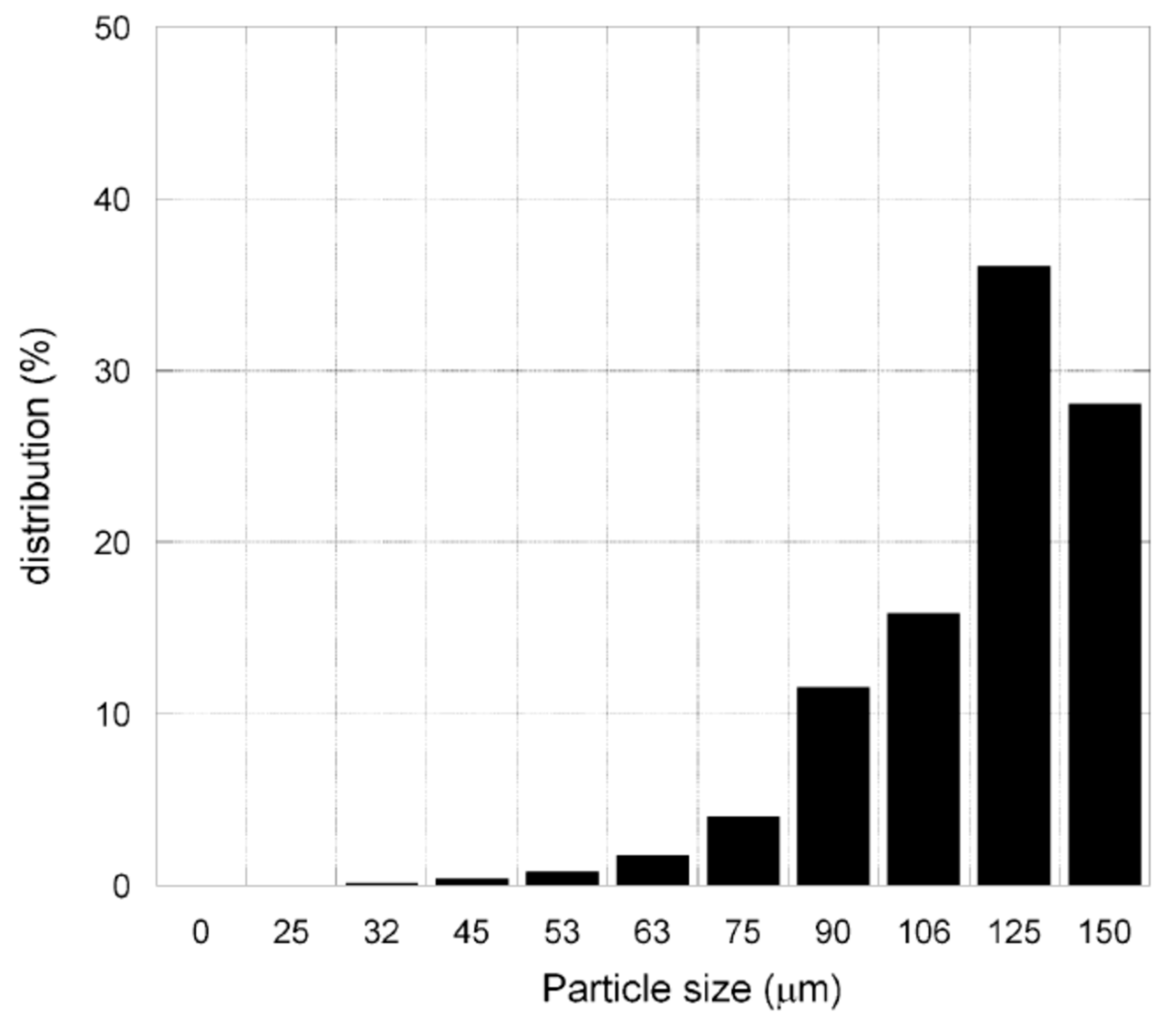
Materials with particle sizes in the 10–150 µm range are preferred (Figure 6);
-
Semi-crystalline polymers with a relatively low melting point and low melting viscosity are also preferred.
By using the design of experiments (DOE), they settled the SLS processing parameters for the different polymer-particles formulations. Testing the tensile and compressive properties for each designed formulation, they observed a nonlinear variation as a function of particles volume fraction. In conclusion, they produced, by means of SLS, 3D components with spatially varying mechanical properties by using particulate-filled functionally graded polymer nanocomposites exhibiting a one-dimensional composition gradient.

3.3. Epoxy Resin Composites

Going on through the years, the enlargement of Rapid Prototyping application fields required more performing photosensitive resins, because the previous ones cannot meet industrial requirements. Thus, simultaneously, both the Industry and the Academia started to develop new photosensitive resins with better mechanical and thermal properties. Yugang et al., in order to improve the processability of the photosensitive resin formulations for SLA, designed composites with Anatase nano-TiO2, treated by a silane coupling agent [31]. They found the best improvement in the tensile strength (89%), whilst for the tensile modulus and flexural strength they recorded an increase of 18% and 6%, respectively. Moreover, the plasticity and the thermal stability of MPR was enhanced. An important aspect highlighted by Yugang and coworkers was that, due to its strong absorption, although nano-TiO2 improves the mechanical and thermal properties, TiO2 content would affect cure depth and green strength greatly when it was over 0.5%. Thus, they proposed further modification of the formulation for decreasing the resin viscosity.
Kurimoto et al. 3D printed out a conical insulating spacer, with height of 10 mm, by using an alumina/UV-cured-resin composite [32]. They used alumina particles of spherical shape with a diameter of more than 20 μm. In total, 40 vol% of filler and 60 vol% of UV curable resin were mixed in a planetary and then degassed, a specimen of 0.3 × 50 × 50 mm was cured by the irradiation of the UV laser of 3D printer and then was cured thermally. Despite the amount of micrometric alumina fillers was 40 vol%, they observed a higher alumina composite’s permittivity compared to the unfilled resin, thus evidencing that the alumina composite was cured by UV.

3.4. Acrylate Composites

Paull et al. designed and fabricated a low-cost thermally conductive composite material, based upon acrylate polymer and microdiamond particles (2–4 μm) at various content, ranging from 10% to 30% (w/v) [33]. Thus, by simply suspending the microparticles within the resin, avoiding any additional chemical reactions or further modifications, and then directly introducing the suspension into the printer, they obtained thermally conducting objects having applications in thermal management and in electronic and fluidic devices. The printed composite exhibited improved heat transfer rates and significantly decreased thermal expansion coefficients, by increasing particles content up to 25 % (w/v), compared to the unmodified starting resin.

3.5. Polyamide Composites

Kim et al. investigated the possibility to reinforce polyamide-12 by using functionalized graphite nanoplatelets, aiming at fabricating prototypes with improved mechanical properties in the SLS process [34]. The structure and the mechanical properties of the obtained nanocomposite were studied and compared with those of neat polyamide-12 and polyamide-12/TiO2 nanocomposite. To obtain a good dispersion of the reinforcement into the matrix, as well as mass manufacturability, solution intercalation in an autoclave was carried out for the synthesis. Aiming to apply the obtained nanocomposites in the SLS process, they studied the particle size distribution. Moreover, by the means of a laser, they layered and sintered the nanocomposite powder to test their feasibility. Tensile tests showed them an increase in the ultimate strength and Young’s modulus for the prepared nanocomposite in respect to those of pristine PA12, confirming that functional groups on a small amount of nanofiller strengthen the interfacial bonding force between filler and matrix without compromising the thermal and rheological behavior, and leading to an improvement of the material properties.

3.6. Polyethylene Glycol Diacrylate Composites

Sirbuly et al. incorporated barium titanate (BaTiO3, BTO) nanoparticles into photoliable polymer solutions and, after exposition to digital optical masks, generated user-defined 3D microstructures [35], demonstrating the feasibility of the 3D optically printing of piezoelectric nanoparticle-polymer composites using digital projection printing. They provided a tool for fabricating 3D piezoelectric polymers and indicated the route for creating highly efficient piezoelectric polymer materials via nanointerfacial tuning. In fact, the nanoparticles’ chemical modification, by using acrylate surface groups forming covalent bonds with the matrix under light exposure, led to an increase in the mechanical-to-electrical conversion efficiency of the composites. A grafting of the nanoparticles to the polymer backbones occurred, due to the crosslink of the matrix with the piezoelectric nanoparticles, enhancing the piezoelectric output of the composites by efficiently funneling mechanical stress to the crystals, thanks to the direct linkage with the flexible polymer matrix (Figure 7).
They observed a piezoelectric coefficient over 10 and 2 times larger, by using a 10% mass loading of chemically modified BTO nanoparticles, in respect to composites with unmodified BTO nanoparticles and unmodified BTO nanoparticles and carbon nanotubes to boost mechanical stress transfer efficiencies, respectively.
Chiappone et al., since the particles’ inclusion in the matrix could be making the printing process more difficult, proposed an in situ generation of nanoparticles after the printing process [36,37]. The 3D structures were fabricated by embedding Silver nitrate in a mixture of polyethylene glycol diacrylate (PEGDA) oligomer and a photoinitiator, and then exposing to a Digital Light Processing (DLP) system. Once fabricated, the material was thermal treated to induce the in situ generation of metal nanoparticles (NPs) in the matrix (Figure 8).
The Italian researchers obtained 3D structures with complex geometries, ranging from simple rectangular structure to more complex honeycomb and helicoidally structures (Figure 9), presenting promising electrical properties and good thermo-mechanical characteristics.
Thus, they concluded that the in situ thermal generation of silver NPs, performed on the printed samples, did not influence the stability of the polymeric structures, representing an alternative to the UV generation.

3.7. Polyurethane Composites

Erb, Martin and Fiore et al., exploiting the AM technologies, proposed a different manufacturing approach, termed as 3D magnetic printing to create highly programmable composites. This new technique, which oriented anisotropic reinforcing particles during the printing of composites using magnetic fields, allowed them to recreate complex bioinspired reinforcement architectures (Figure 10) delivering enhanced material performance compared with monolithic structures [38].
They started from concentric structures of the osteon to the layered ones of nacre to the cholesteric structures of the peacock mantis shrimp. To realize their idea, Erb and his colleagues used Al2O3 particles in platelet form (average diameter of 7.5 µm; average thickness of 350 nm), magnetized by superparamagnetic iron oxide nanoparticles. The mixture was coated, stirred overnight using a magnetic stir bar, then the particles are filtered and dried. Once drying was completed, the magnetized alumina particles were added to a photopolymer (aliphatic urethane diacrylate and isobornyl acrylate) at desired volume fractions. In a such way, they produced reinforcement architectures of ceramic microparticles exhibiting feature sizes of 90 mm and enabling materials with increased stiffness, strength and hardness properties, that is maximizing material properties.
Parallel to the 3D magnetic printing, Studart, Kokkinis andl Schaffner intuited that, by controlling the anisotropic particles orientation during a direct ink-writing process, this methodology can offer a much wider design space beyond unusual shaping, thus proposing the multimaterial magnetically assisted 3D printing platform (MM-3D printing) [39].
The Swiss researchers introduced the concept of five-dimensional design space also included, besides the 3D shaping capabilities of additive manufacturing, local control of composition (+1D), and particle orientation (+1D), thus developing a printing platform to enable 5D programmability. Their work affirmed three key features for the use of this platform in the design and fabrication of 3D self-shaping objects (Figure 11): the relationship between ink rheology and the shape distortion of filaments, the dynamics of the alignment of anisotropic particles under an external magnetic field, the correlation between shape changes in swelling objects and the geometry and properties of their constituent materials. Particle orientation control was demonstrated by applying low magnetic fields on deposited inks pre-loaded with magnetized stiff platelets, highlighting the ink formulation as a crucial aspect (i.e., particle orientation, composition and 3D shape control). Their ink formulation contained polyurethane acrylate (PUA) oligomers, reactive diluents, photoinitiator, rheology modifier and alumina platelets. In order to reach their printing purposes, they need inks with flow responses ranging from pure Newtonian to viscoelastic, to achieve orientation and shape control, respectively. Such a wide spectrum was obtained by incorporating fumed silica (FS) particles of 5–30 nm as rheological modifier in the initial resin solution, by using its hydrophilic/hydrophobic characteristics at needing. The wide design space offered by the MM-3D printing platform proposed by Studart and his colleagues opened a new route for the design and fabrication of functional parts through additive manufacturing technology, enlarging the possible applications. Reconfigurable key–lock connectors based on shape-changing parts (Figure 11) can potentially be used as autonomously triggered flexible joints, soft building blocks with reversible clicktype inks as well as selective pick-and-place systems in soft robotics.

3.8. Polycarbonate Composites

The inherent flexibility of 3D printing was also used to design and fabricate material-extrusion three-dimensional printing (ME3DP) structures for applications ranging from antennas and sensing to space-based cube satellites (CubeSats). Aiming at probe 3D printing in the rapid creation of space-based devices, such as CubeSates, Roberson et al. proposed the fabrication and characterization of tungsten-doped polycarbonate composites for X-ray radiation-shielding applications [40]. They chose tungsten, for designing composites, due its high density, X-ray shielding capability and non-reactivity during the chemical functionalization at extrusion temperature. In particular, tungsten’s high density allowed the use of low percentage considering that for these structures weight requirements are of high priority. In addition, the low-level loading of tungsten was necessary because the addition of radiation-blocking microparticles was expected to interrupt the polymer matrix and reduce such mechanical properties as tensile strength, thus a low-volume fraction of particles would not affect composite yield strength properties. The polycarbonate–tungsten composite was shown to be printable and resulted in a marked improvement in X-ray radiation shielding (~10%), even for low-volume loadings of tungsten (~0.3 vol%), thus revealing the ability of tungsten micro-particles to act as a radiation shield within a 3D printable polymer matrix composite without greatly affecting the mechanical properties, as is necessary for most space-based applications.

3.9. ABS Composites

Nikzad et al. affirmed the need to investigate the flow of the composite material in liquefier head, to make possible a prediction of the behavior of the composites in the course of FDM process. No such study is available considering the geometry of the liquefier head. The research group at the Swinburne University of Technology presented a 2D and 3D numerical analysis of the melt flow behavior of ABS plastic containing 10% volume fraction of iron, as well as a small fraction of surfactant, through the 90° bent tube of the liquefier head of the FDM process, by using ANSYS FLOTRAN and CFX finite element packages [41]. The results obtained by both of the analyses have been compared and showed a very good correlation in predicting the flow behavior. The flexible filaments of ABS-iron composites have been successfully produced and processed in a FDM300 machines developed by Stratasys to produce sample parts.
The research group at the Swinburne University of Technology, continuing its study in the field, pointed out the attention on a series of critical aspects deemed necessary for obtaining high quality composite feedstock filaments for FDM. In particular, considering that the filaments require high stiffness and lower melt viscosity and the high metal powder loading in the polymer matrix, the viscosity of the composite was increased at the expense of dispersion. For this reason, they considered surfactants and plasticizers in their composite formulation. Aiming to find the correct combination of the described properties, they studied the thermal and mechanical properties of new metal-particle-filled ABS composites for rapid prototyping process [42], obtained by controlled centrifugal mixing, thermally compounded through a single-screw extruder and compression moulding.
To develop appropriate feed stock filaments, mixtures of iron and copper powder with ABS powder were chosen with varying volume fractions of metal powder (5%, 10%, 20%, 30% and 40%). The flexible filaments of the new composite material have been successfully produced, showing great promise for application in functional parts and direct rapid tooling on the FDM systems (Figure 12). Finally, they observed higher stiffness in comparison to the unreinforced polymers, resulting in withstanding higher injection moulding pressures.
Torrado Perez and colleagues explored the effect of the addition of TiO2 to ABS on the mechanical and physical properties of the polymer. In particular, they evaluated tensile testing data and fracture surface morphology for two ABS matrix-printable composites (one additivated with particles and the other one with fibers) and one ABS/elastomer blend [43]. They produced ABS monofilaments (diameter of 1.77 mm) by using a Twin Screw Extruder/Compounder Model with co-rotating, intermeshing screws, loaded with 5 wt.% of jute fiber, TiO2 and thermoplastic elastomer (TPE), respectively. Because of the anisotropic nature of this fabrication technique the mechanical properties of the designed specimens are greatly influenced by the fabrication orientation on the machine as well as the print raster path (also known as fill pattern) [44,45,46]. For this reason, two sets of specimens were produced for each material type, the first printed in the XYZ direction and the second in the ZXY one (Figure 13).
In order to obtain a part with a lower amount of air gaps between the deposited threads, they fabricated all the samples with the same parameters on the machine, which were previously iterated to get the optimum filling on the sample without leading to dragging of the part, because of an excess of deposited material (Figure 14).
The effect of build orientation on the mechanical properties and fracture surface was studied, as one of the major flaws of additive manufacturing is the anisotropy on the 3D-printed items. Among the three different additives chosen for as reinforcing agents for ABS, the system reinforced with TiO2 showed the higher ultimate tensile strength compared with pure ABS and the other composite systems, despite its fracture characteristics indicated brittle fracture. Finally, the fracture surfaces exhibited different morphological characteristics as a function of the two build orientations used for the preparation of the specimens. The presence of cavities was more abundant for the sample prepared in the ZXY direction, due to a failure of the interface between printed layers.
In the middle of these last twenty years, more or less, both academics and industry noticed, when FDM was used to make large-scale 3D objects, the distortion of the final products resulting from the thermal expansion of the thermoplastic filaments. Even though, at that time, some printer manufacturer included heated plates or used specific glues, various researchers focused their studies on the development of filaments with metal particles, trusting that embedded metal particles can provided a solution to distortion of the final product in largescale 3D printing. In this context, it takes the shape the idea of Kim et al. of restricting the distortion of the final product during the printing process, by improving the thermal conductivity of the thermoplastic with a drop in the coefficient of thermal expansion of the materials by adding metal particles into the matrix [47].
They used ABS as the thermoplastic material, and copper and iron powders metal particles, varying from 0 to 40 wt.%. The printing parameters. such as temperature (adjusted from 190 °C to 220 °C) and fill density (changed in the range of 20–80%), were varied to observe their effects on the viscosity and the tensile strength of the final product, which was made with the FDM process. Metal/polymer filaments were manufactured by the filament extruder with a diameter of 1.75 mm (Figure 15). They found that the ABS’s viscosity, at the different temperatures, followed a relationship between tensile strength and printing temperature, thus confirming a decrease in the tensile strength on increasing the particles’ loading. Furthermore, they observed an improvement in the thermal conductivity of the composite filament by increasing the metal content, thus allowing the printing of the filament without any distortion by the thermal expansion of thermoplastics. When the specimen was printed with 60% fill density, it had the highest ductility.
Singh et al. tried to improve the properties of commercial ABS for FDM components by adding Nylon6-Al-Al2O3 at different proportions of Al and Al2O3 [48]. In particular, the effect of the abrasive surface, the duration of the run and the applied load on friction and the wear behaviour of the different composites in comparison to the commercial ABS filaments have been studied. The tribological tests were carried out on a pin on disc arrangement at room temperature under 5, 10, 15 and 20 N loads, having a sliding rate of 1.36 m/s and run times of 5 and 10 min, respectively. They observed that the presence of particles gives to the composite higher wear resistance than ABS, due to adhesion as well. The composite materials showed less friction coefficients, friction force and a slight rise in temperature, demonstrating high stiffness and stability when operating at a high sliding velocity during a long run.
Isakov et al. studied the feasibility of using bespoke polymer-based feedstock composite in AM to produce dielectric resonator structures, with strong anisotropy matching the ‘Wiener bounds’ [49] description of property anisotropy in layered composite systems. Their specimens were printed through a dual-filament FDM, utilizing bespoke feedstock filament comprised a polymer-based micro-ceramic composite with controlled permittivity and loss [50]. According to this technique, two types of filament (loaded onto two extruder heads) were used simultaneously, i.e., ABS and polypropylene (PP) modified with micro-particles of different perovskite oxides, such as BaTiO3, CaTiO3 and Ba0.64Sr0.36TiO3 (powder diameters < 3 μm). They proposed the 3D printing of the dielectric structures, affirming the possibility to move towards the manufacturing of structures with metamaterial electromagnetic properties and tunable operational frequencies. The designed structures consisting of oriented dielectric stripes with alternating dielectric permittivity possessed well-defined artificial anisotropy of effective permittivity, and a Mie-type resonance, showing the potential for near-zero or less than unity values of effective permittivity and revealing a great potential for using fused-deposition 3D printing in manufacturing novel electromagnetic devices.
Jaya Christiyan et al. fabricated and characterized ABS + hydrous magnesium silicate composite, varying process parameters like different layer thickness (0.2 × 0.25 × 0.3 mm) and different printing speeds (30, 40 and 50 mm/s). They found a trend for which tensile and flexural strength increase as a function of low printing speed and layer thickness, probably due to a better bonding with the previous layer. In particular, they observed the high values of tensile and flexural strength at 0.2 mm of layer thickness and a printing speed of 30 mm/s [51].
We have seen as dielectric materials, widely used in the electronic area, may be 3D printed using a variety of techniques, especially FDM. The hot spot in this case is represented by the limited range of dielectric permittivities of the commercial filaments.
To overcome this limitation, Grant et al. verified the insertion of ceramic particles in a standard material for the desktop-fused deposition 3D printers, ABS [52]. The choice for microparticles fell down on BaTiO3 due to its unusually high ε’. Comparing the dielectric properties of the printed parts against the bulk unprinted material, they recorded reproducibility over the entire process, suggesting that the technique may be employed as a viable manufacturing process for dielectric composites (Figure 16). However, Grant and his colleagues highlighted the brittleness of the filament following the addition of ceramic particles as a limitation in the compatibility of the composite with the fused deposition printing process and they indicated 70 wt% (29 vol%) of BaTiO3 like the maximum fraction can be used.

4. Conclusions

The modification of the most commonly used inks for 3D printers has opened the doors for a rush of new developments and possibilities, inspiring new research into the rapid prototyping of complex objects with improved material properties. All these studies significantly contributed to the field of materials science but most of the time they could only be tested on desktop printers, because the commercial 3D printers are designed for printing specific resins and are not compatible with modified inks. Thus, to really affect additive manufacturing, the proposed solution should be tested by the major 3D companies (some of them have done it, others are doing it) in order to verify the impact of the composites in problems such as agglomerate formation, the blocking of printer heads, non-adhesion, and theor alteration of curing times.

Funding

Ignazio Blanco is grateful to the University of Catania for supporting this research within the “Bando-CHANCE” and to the Department of Civil Engineering and Architecture within “Piano per la Ricerca 2016-2018–Linea Intervento 1 and 2”.

Conflicts of Interest

The author declares no conflict of interest.

References

  1. Blanco, I.; Cicala, G.; Ognibene, G.; Rapisarda, M.; Recca, A. Thermal properties of polyetherimide/polycarbonate blends for advanced applications. Polym. Degrad. Stab. 2018, 154, 234–238. [Google Scholar] [CrossRef]
  2. Huang, S.H.; Liu, P.; Mokasdar, A.; Hou, L. Additive manufacturing and its societal impact: A literature review. Int. J. Adv. Manuf. Technol. 2013, 67, 1191–1203. [Google Scholar] [CrossRef]
  3. Hull, C.W. Apparatus for Production of Three-Dimensional Objects by Stereolithography. U.S. Patent 4575330A, 11 March 1986. [Google Scholar]
  4. Crump, S.S. Rapid prototyping using FDM. Mod. Cast. 1992, 82, 36. [Google Scholar]
  5. Kohár, R.; Stopka, M.; Weis, P.; Spisak, P.; Šteininger, J. Modular 3D Printer Concept. In Current Methods of Construction Design: Proceedings of the ICMD 2018; Medvecký, Š., Hrček, S., Kohár, R., Brumerčík, F., Konstantová, V., Eds.; Springer: Berlin, Germany, 2020; p. 484. ISBN 978-3-030-33146-7. [Google Scholar] [CrossRef]
  6. Feygin, M. Apparatus and Method for Forming an Integral Object from Laminations. U.S. Patent 5354414A, 4 April 1991. [Google Scholar]
  7. Zong, G.; Wu, Y.; Tran, N.; Lee, I.; Bourell, D.L.; Beaman, J.; Marcus, H.L. Direct Selective Laser Sintering of High Temperature Materials. In Proceedings of the 3rd Solid Freeform Fabrication Symposium, Austin, TX, USA, 3–5 August 1992; pp. 72–85. [Google Scholar]
  8. Provaggi, E.; Kalaskar, D.M. 3D printing families: Laser, powder, nozzle based techniques. In 3D Printing in Medicine; Kalaskar, E., Ed.; Woodhead Publishing: Sawston, UK, 2017; p. 24. ISBN 978-0-08-100717-4. [Google Scholar]
  9. Xu, M.; David, J.M.; Kim, S.H. The Fourth Industrial Revolution: Opportunities and Challenges. Int. J. Financ. Res. 2018, 9. [Google Scholar] [CrossRef] [Green Version]
  10. Turner, B.N.; Strong, R.; Gold, S.A. A review of melt extrusion additive manufacturing processes: I. Process design and modeling. Rapid Prototyp. J. 2014, 20, 192–204. [Google Scholar] [CrossRef]
  11. Mpofu, T.P.; Mawere, C.; Mukosera, M. The Impact and Application of 3D Printing Technology. Int. J. Sci. Res. 2014, 3, 2148–2152. [Google Scholar]
  12. Wang, X.; Jiang, M.; Zhou, Z.; Gou, J.; Hui, D. 3D printing of polymer matrix composites: A review and prospective. Compos. Part B 2017, 110, 442–458. [Google Scholar] [CrossRef]
  13. Shahrubudin, N.; Lee, T.C.; Ramlan, R. An Overview on 3D Printing Technology: Technological, Materials, and Applications. Procedia Manuf. 2019, 35, 1286–1296. [Google Scholar] [CrossRef]
  14. Blanco, I. The Rediscovery of POSS: A Molecule Rather than a Filler. Polymers 2018, 10, 904. [Google Scholar] [CrossRef] [Green Version]
  15. Shofner, M.L.; Lozano, K.; Rodriguez-Macias, F.J.; Barrera, E.V. Nanofiber-Reinforced Polymers Prepared by Fused Deposition Modeling. J. Appl. Polym. Sci. 2003, 89, 3081–3090. [Google Scholar] [CrossRef]
  16. Gray, R.; Baird, D.; Helge Bøhn, J. Effects of processing conditions on short TLCP fiber reinforced FDM parts. Rapid Prototyp. J. 1998, 4, 14–25. [Google Scholar] [CrossRef]
  17. Zhong, W.; Li, F.; Zhang, Z.; Song, L.; Li, Z. Short fiber reinforced composites for fused deposition modeling. Mater. Sci. Eng. A 2001, 301, 125–130. [Google Scholar] [CrossRef]
  18. Tekinalp, H.L.; Kunc, V.; Velez-Garcia, G.M.; Duty, C.E.; Love, L.J.; Naskar, A.K.; Blue, C.A.; Ozcan, S. Highly oriented carbon fiber-polymer composites via additive manufacturing. Compos. Sci. Technol. 2014, 105, 144–150. [Google Scholar] [CrossRef] [Green Version]
  19. Ning, F.; Cong, W.; Qiu, J.; Wei, J.; Wang, S. Additive manufacturing of carbon fiber reinforced thermoplastic composites using fused deposition modeling. Compos. Part B 2015, 80, 369–378. [Google Scholar] [CrossRef]
  20. Yang, C.; Tian, X.; Liu, T.; Cao, Y.; Li, D. 3D printing for continuous fiber reinforced thermoplastic composites: Mechanism and performance. Rapid Prototyp. J. 2017, 23, 209–215. [Google Scholar] [CrossRef]
  21. Zhang, W.; Wu, A.S.; Sun, J.; Quan, Z.; Gu, B.; Sun, B.; Cotton, C.; Heider, D.; Chou, T.-W. Characterization of residual stress and deformation in additively manufactured ABS polymer and composite specimens. Compos. Sci. Technol. 2017, 150, 102–110. [Google Scholar] [CrossRef]
  22. Lewicki, J.P.; Rodriguez, J.N.; Zhu, C.; Worsley, M.A.; Wu, A.S.; Kanarska, Y.; Horn, J.D.; Duoss, E.B.; Ortega, J.M.; Elmer, W.; et al. 3D-Printing of Meso-structurally Ordered Carbon Fiber/Polymer Composites with Unprecedented Orthotropic Physical Properties. Sci. Rep. 2017, 7, 43401. [Google Scholar] [CrossRef] [Green Version]
  23. Mahajan, C.; Cormier, D. 3D Printing of Carbon Fiber Composites with Preferentially Aligned Fibers. In Proceedings of the 2015 Industrial and Systems Engineering Research Conference, Nashville, TN, USA, 30 May–2 June 2015; Volume 1, pp. 64–73, ISBN 978-1-5108-1368-7. [Google Scholar]
  24. Van der Klift, F.; Koga, Y.; Todoroki, A.; Ueda, M.; Hirano, Y.; Matsuzaki, R. 3D Printing of Continuous Carbon Fibre Reinforced Thermo-Plastic (CFRTP) Tensile Test Specimens. Open J. Compos. Mater. 2016, 6, 18–27. [Google Scholar] [CrossRef] [Green Version]
  25. Blok, L.G.; Longana, M.L.; Yu, H.; Woods, B.K.S. An investigation into 3D printing of fiber reinforced thermoplastic composites. Addit. Manuf. 2018, 22, 176–186. [Google Scholar] [CrossRef]
  26. Matsuzaki, R.; Ueda, M.; Namiki, M.; Jeong, T.-K.; Asahara, H.; Horiguchi, K.; Nakamura, T.; Todoroki, A.; Hirano, Y. Three-dimensional printing of continuous-fiber composites by in-nozzle impregnation. Sci. Rep. 2016, 6, 23058. [Google Scholar] [CrossRef]
  27. Fu, S.-Y.; Feng, X.-Q.; Lauke, B.; Mai, Y.-W. Effects of particle size, particle/matrix interface adhesion and particle loading on mechanical properties of particulate–polymer composites. Composites 2008, 39, 933–961. [Google Scholar] [CrossRef]
  28. Tjong, S. Structural and mechanical properties of polymer nanocomposites. Mater. Sci. Eng. 2006, 53, 73–197. [Google Scholar] [CrossRef]
  29. Zheng, H.; Zhang, J.; Lu, S.; Wang, G.; Xu, Z. Effect of core-shell composite particles on the sintering behavior and properties of nano-Al2O3/polystyrene composite prepared by SLS. Mater. Lett. 2006, 60, 1219–1223. [Google Scholar] [CrossRef]
  30. Chung, H.; Das, S. Functionally graded Nylon-11/silica nanocomposites produced by selective laser sintering. Mater. Sci. Eng. A 2008, 487, 251–257. [Google Scholar] [CrossRef]
  31. Yugang, D.; Yuan, Z.; Yiping, T.; Dichen, L. Nano-TiO2-modified photosensitive resin for RP. Rapid Prototyp. J. 2011, 17, 247–252. [Google Scholar] [CrossRef]
  32. Kurimoto, M.; Yamashita, Y.; Ozaki, H.; Kato, T.; Funabashi, T.; Suzuoki, Y. 3D printing of conical insulating spacer using alumina /UV-cured-resin composite. In Proceedings of the 2015 IEEE Conference on Electrical Insulation and Dielectric Phenomena (CEIDP), Ann Arbor, MI, USA, 18–21 October 2015; pp. 463–466. [Google Scholar] [CrossRef]
  33. Kalsoom, U.; Peristyy, A.; Nesterenko, P.N.; Paull, B. A 3D printable diamond polymer composite: A novel material for fabrication of low cost thermally conducting devices. RSC Adv. 2016, 6, 38140–38147. [Google Scholar] [CrossRef]
  34. Kim, H.C.; Hahn, H.T.; Yang, Y.S. Synthesis of PA12/functionalized GNP nanocomposite powders for the selective laser sintering process. J. Compos. Mater. 2012, 47, 501–509. [Google Scholar] [CrossRef]
  35. Kim, K.; Zhu, W.; Qu, X.; Aaronson, C.; McCall, W.R.; Chen, S.; Sirbuly, D.J. 3D Optical Printing of Piezoelectric Nanoparticle_Polymer Composite Materials. ACS Nano 2014, 8, 9799–9806. [Google Scholar] [CrossRef]
  36. Fantino, E.; Chiappone, A.; Roppolo, I.; Manfredi, D.; Bongiovanni, R.; Pirri, C.F.; Calignano, F. 3D printing of conductive complex structures with in situ generation of silver nanoparticles. Adv. Mater. 2016, 28, 3712–3717. [Google Scholar] [CrossRef]
  37. Fantino, E.; Chiappone, A.; Calignano, F.; Fontana, M.; Pirri, F.; Roppolo, I. In Situ Thermal Generation of Silver Nanoparticles in 3D Printed Polymeric Structures. Materials 2016, 9, 589. [Google Scholar] [CrossRef]
  38. Martin, J.J.; Fiore, B.E.; Erb, R.M. Designing bioinspired composite reinforcement architectures via 3D magnetic printing. Nat. Commun. 2015, 6, 8641. [Google Scholar] [CrossRef] [Green Version]
  39. Kokkinis, D.; Schaffner, M.; Studart, A. Multimaterial magnetically assisted 3D printing of composite materials. Nat. Commun. 2015, 6, 8643. [Google Scholar] [CrossRef] [PubMed] [Green Version]
  40. Shemelya, C.M.; Rivera, A.; Perez, T.; Rocha, C.; Liang, M.; Yu, X.; Kief, C.; Alexander, D.; Stegeman, J.; Xin, H.; et al. Mechanical, Electromagnetic, and X-ray Shielding Characterization of a 3D Printable Tungsten–Polycarbonate Polymer Matrix Composite for Space-Based Applications. J. Electron. Mater. 2015, 44, 2598–2607. [Google Scholar] [CrossRef]
  41. Nikzad, M.; Masood, S.H.; Sbarski, I.; Groth, A. A study of melt flow analysis of an ABS-Iron composite in fused deposition modelling process. Tsinghua Sci. Technol. 2009, 14, 29–37. [Google Scholar] [CrossRef]
  42. Nikzad, M.; Masood, S.H.; Sbarski, I. Thermo-mechanical properties of a highly filled polymeric composites for Fused Deposition Modeling. Mater. Des. 2011, 32, 3448–3456. [Google Scholar] [CrossRef]
  43. Torrado Perez, A.R.; Roberson, D.A.; Wicker, R.B. Fracture Surface Analysis of 3D-Printed Tensile Specimens of Novel ABS-Based Materials. J. Fail. Anal. Prev. 2014, 14, 343–353. [Google Scholar] [CrossRef]
  44. Ahn, S.-H.; Montero, M.; Odell, D.; Roundy, S.; Wright, P.K. Anisotropic material properties of fused deposition modeling ABS. Rapid Prototyp. J. 2002, 8, 248–257. [Google Scholar] [CrossRef] [Green Version]
  45. Bellini, A.; Guceri, S. Mechanical characterization of parts fabricated using fused deposition modeling. Rapid Prototyp. J. 2003, 9, 252–264. [Google Scholar] [CrossRef]
  46. Es-Saida, O.S.; Foyosa, J.; Noorania, R.; Mendelsona, M. Effect of layer orientation on mechanical properties of rapid prototyped samples. Mater. Manuf. Process. 2000, 15, 107–122. [Google Scholar] [CrossRef]
  47. Hwang, S.; Reyes, E.I.; Moon, K.; Rumpf, R.C.; Kim, N.S. Thermo-mechanical Characterization of Metal/Polymer Composite Filaments and Printing Parameter Study for Fused Deposition Modeling in the 3D Printing Process. J. Electron. Mater. 2015, 44, 771–777. [Google Scholar] [CrossRef]
  48. Boparai, K.; Singh, R.; Singh, H. Comparison of tribological behaviour for Nylon6-Al-Al2O3 and ABS parts fabricated by fused deposition modelling. Virtual Phys. Prototyp. 2015, 10, 59–66. [Google Scholar] [CrossRef]
  49. Aspnes, D.E. Bounds on allowed values of the effective dielectric function of two component composites at finite frequencies. Phys. Rev. B Condens. Matter 1982, 25, 1358–1361. [Google Scholar] [CrossRef]
  50. Isakov, D.V.; Lei, Q.; Castles, F.; Stevens, C.J.; Grovenor, C.R.M.; Grant, P.S. 3D printed anisotropic dielectric composite with meta-material features. Mater. Des. 2016, 93, 423–430. [Google Scholar] [CrossRef]
  51. Jaya Christiyana, K.G.; Chandrasekharb, U.; Venkateswarlu, K. A study on the influence of process parameters on the Mechanical Properties of 3D printed ABS composite. IOP Conf. Series Mater. Sci. Eng. 2016, 114, 012109. [Google Scholar] [CrossRef]
  52. Castles, F.; Isakov, D.; Lui, A.; Lei, Q.; Dancer, C.E.J.; Wang, Y.; Janurudin, J.M.; Speller, S.C.; Grovenor, C.R.M.; Grant, P.S. Microwave dielectric characterisation of 3D-printed BaTiO3/ABS polymer composites. Sci. Rep. 2016, 6, 22714. [Google Scholar] [CrossRef] [Green Version]
Figure 1. Sketch of the samples. Reprinted from [17], © 2001 with permission from Elsevier.
Jcs 04 00042 g001
Figure 2. Schematic presentation of 3D-printed fiber-reinforced composite by fused deposition modeling. Reprinted from [18], © 2014 with permission from Elsevier.
Jcs 04 00042 g002
Figure 3. SEM image of different categories of the specimen porosity (carbon fiber content is 10 wt%; carbon fiber length is 150 mm). Reprinted from [19], © 2015, with permission from Elsevier.
Jcs 04 00042 g003
Figure 4. Example of meso-structure of 3D-printed parts with raster angle. Reprinted from [22], © 2018, with permission from Elsevier.
Jcs 04 00042 g004
Figure 5. High resolution numerical simulation of a carbon fiber loaded ink under conditions of microextrusion during a direct ink writing (DIW) printing process to form an additively manufactured carbon-fiber-reinforced composite (AMCFRC). (A) represents the total computational domain for these simulations which cylindrical/conical volume, terminating in a 400-μm orifice and is representative of the last 2 mm of the actual extrusion head. (B,C) are the side and end views showing the initial (random) fiber partial distributions within the contiguous phase. (D) represents the time-resolved evolution of the fiber orientations in 3D within the computational domain under the simulated conditions of printing. Note that the simulation predicts what appears to be a wall dominated shear alignment process that follows closely the predicted velocity profile of the fluid. Reprinted from [23], © 2017, with permission from Springer Nature.
Jcs 04 00042 g005
Figure 6. Particle size distribution of Nylon-11 (RilsanD80) by sieve analysis. Reprinted from [30], © 2008, with permission from Elsevier.
Jcs 04 00042 g006
Figure 7. (a) Schematic of the DPP setup that projects dynamic digital masks on the photoliable piezoelectric nanoparticle–polymer composite solution. Any pattern can be digitized, and the digital mirror device projects the image onto the polymer solution. (b) A scanning electron micrograph of barium titanate (BTO) nanoparticles grown via a hydrothermal process. (c) A cartoon showing the piezoelectric polymer composite materials with BTO nanoparticles (orange circles) grafted to a polyethylene glycol diacrylate (PEGDA) matrix (black lines). The zoom-in shows the TMSPM linker covalently linked to the nanoparticle surface and cross-linked with the PEGDA matrix. Reprinted from [35], © 2014, with permission from American Chemical Society.
Jcs 04 00042 g007
Figure 8. Sketch of Digital Light Processing (DLP) setup that projects dynamic digital masks on the photocurable formulation featuring the formation of the polyethylene glycol diacrylate structure. Subsequent thermal treatment, with the formation of the silver nanoparticles by reduction of the metal precursors. Reprinted from [37], © 2016, with permission from MDPI AG.
Jcs 04 00042 g008
Figure 9. Three-dimensional objects produced by the DLP technique from the formulation containing polyethylene glycol diacrylate (PEGDA) and 15 phr of silver nitrate. (a) Honeycomb structure, as printed; (b,c) samples after the thermal treatments; the metallic aspect induced by the presence of the silver nanoparticles is clearly visible. Reprinted from [37], © 2016, with permission from MDPI AG.
Jcs 04 00042 g009
Figure 10. Bioinspired composites with microstructured architectures can be recreated with 3D magnetic printing. (a) The Haliotidae sp. Abalone shell exhibits a layered structure of calcite prisms topping in-plane aragonite platelets (nacre). This architecture is (b) simplified and (c) 3D magnetic printed. (d) The dactyl club of the peacock mantis shrimp exhibits a cholesteric architecture of mineralized chitin fibres. This architecture is (e) simplified and (f) 3D magnetic printed. (g) The mammalian cortical bone exhibits concentric plywood structures of lamellae-reinforced osteons. This architecture is (h) simplified and (i) 3D magnetic printed. All printed microstructures are acrylateurethane co-polymers reinforced by 15 volume percent alumina platelets. Scale bar: 5 mm in (a); 25 mm in (c); 15 mm in (d); 50 mm (black) and 20 mm (white) in (f); 200 mm in (g); and 5mm (black) and 25 mm (white) in (i). Reprinted from [38], © 2015, with permission from Springer Nature.
Jcs 04 00042 g010
Figure 11. Soft mechanical fasteners fabricated through the programmable MM-3D printing of shape-changing objects. (a; Top) Drawings and actual printed cuboids before the shape change. This part is named cuboid 1. (a; Bottom) Finite element simulations and actual pictures of the cuboids after the shape change. At the bottom right, the simulated cross-section of the cuboid is superimposed on a picture of the actual part to illustrate the good agreement between experimental and predicted curvatures. Scale bars, 10 mm. (b) Cuboid-mediated fastening of two tubes achieved through the shape change of the printed object. Scale bar, 20 mm. (c) Cuboid object with same architecture as in a but containing anisotropic platelets magnetically aligned in different orientations within the soft phase. This part is named cuboid 2. The platelets are aligned horizontally in the top, darker half and vertically in the bottom, brighter half. Scale bar, 10 mm. εs is the swelling strain. (d, Left) Representative stress–strain curves of printed materials comprising the soft phase reinforced with platelets aligned in different orientations. (d, Right) Elastic modulus (E), strength (σ) and strain-at-rupture (εr) of the printed materials with different textures. Error bars show s.d. (n = 5). (e, Top) Drawings and actual printed key–lock objects before the shape change. (e; Bottom) Finite element simulations and actual pictures of the key–lock structure after the shape change. Scale bars, 15 mm. (f) Mechanical fastening enabled by the shape changing key–lock architecture. Scale bar, 15 mm. In all drawings, light and dark grey colours indicate soft and hard phases, respectively. Reprinted from [39], © 2015, with permission from Springer Nature.
Jcs 04 00042 g011
Figure 12. Parts produced on FDM3000 using the new Iron/ acrylonitrile–butadiene–styrene (ABS) composites. (a) Test samples of composite and ABS, and (b) prototype parts of composite. Reprinted from [42], © 2011, with permission from Elsevier.
Jcs 04 00042 g012
Figure 13. Printing directions. Reprinted from [43], © 2014, with permission from Springer Nature.
Jcs 04 00042 g013
Figure 14. Samples (vertical above, horizontal below): (a) ABS and jute fiber, (b) ABS and TiO2, (c) ABS with thermoplastic elastomer (TPE), and (d) pure ABS. Reprinted from [43], © 2014, with permission from Springer Nature.
Jcs 04 00042 g014
Figure 15. ABS-Cu filament and 3D structure: (a) fused deposition modeling (FDM) filament and (b) bike key chain. Reprinted from [47], © 2014, with permission from Springer Nature.
Jcs 04 00042 g015
Figure 16. Three-dimensional-printed polymer composite parts. (a) Example rod-connected diamond photonic crystal structures printed in ABS polymer (left, ε′ = 2.57) and 50 wt% BaTiO3/ABS polymer composite (right, ε′ = 4.95). Scale: each cubic structure has overall side length of 32 mm (8 mm unit cell). (b) Example 1D, 2D, and 3D periodic structures and a 1D graded structure printed using a combination of ABS polymer and 50 wt% BaTiO3 in ABS polymer composite. Scale: each cubic structure has side length of 16 mm. Reprinted from [51], © 2016, with permission from Springer Nature.
Jcs 04 00042 g016

