Article

The Effects of Geometry and Chemical Composition of Nanoparticles on The Fracture Toughness of iPP Nanocomposites

1
The Institute of Chemistry, The Casali Center of Applied Chemistry and the Center for Nanoscience and Nanotechnology, The Hebrew University of Jerusalem, Jerusalem 9190401, Israel
2
School of Materials Science & Engineering, Nanyang Technological University, Singapore 639798, Singapore
*
Author to whom correspondence should be addressed.
J. Compos. Sci. 2020, 4(1), 24; https://doi.org/10.3390/jcs4010024
Submission received: 24 December 2019 / Revised: 28 January 2020 / Accepted: 24 February 2020 / Published: 29 February 2020
(This article belongs to the Special Issue Recent Advances in Carbon Nanotube Composites)

Abstract

:
This research deals with possible hybrid effects in the fracture energy of hybrid nanocomposites while taking a critical approach toward the currently-prevailing engineering practice of applying classical composite micromechanics to nanocomposites. For this purpose, different nanoparticles were embedded in an isotactic polypropylene matrix. The particles had different geometries (fibrous and platelets) and different chemical structures (organic vapor grown carbon nanofibers (VGCF); graphene nanoplatelets (GNP); and inorganic nanoclays, SiO2 nanofibers, and ZrO2 nanofibers). Almost all the composite systems presented improvements in the fracture energy, whereas the iPP/VGCF/GNP presented a positive hybrid effect. The main conclusion was that each nanocomposite system should be analyzed individually according to the constituent properties; the quality of the dispersion; and, primarily, by the type of interaction between the particles and the matrix.

1. Introduction

It is well-known that nanofillers may increase the properties of the matrix in composite materials. The combination of two different fillers in one matrix generates a hybrid composite material that may present enhanced properties due to the combination of the fillers. Wtaife et al. produced a fiber-reinforced concrete (FRC) hybrid with polyvinylalcohol (PVA) and polyolefin fibers and showed that the hybrid composite improved the tensile strength of the concrete and changed it from a brittle to a ductile material while reducing its compressive properties [1]. Chen et al. prepared a flame-retardant polypropylene (PP) films with graphene nanoplatelets (GNP) alone and with magnesium hydroxide (MH). This combination resulted in enhanced thermal stability, reduced burning rate, improved tensile performance, and improved Young’s modulus [2].
Shajariet et al. studied a system of polypropylene with carbon nanotubes (CNT) and stainless-steel fibers (SSF) at different filler loads. For a specific total load (1.75 vol% of each filler), the hybrid system that contained both types of fillers had the highest yield strain and highest electromagnetic interference (EMI) [3]. Li et al. investigated a system of poly(vinyl alcohol) enclosed in multiwalled CNT and fully exfoliated graphene oxide (GO) sheets and tested different filler compositions. They found that the system that contained 1 wt % of GO and 0.5 wt % of CNT could receive a hybrid and even a synergistic effect on the yield strength and Young’s modulus (increased by 48% and 31%, respectively). Such increases are higher than the sum of the improvement of each of the parent composites alone [4]. Zakuwan et al. examined a system of k-carrageenan with hybridization of cellulose nanocrystals (CNCs) and organically modified montmorillonite (OMMT). The total filler composition was 4%, with a ratio of 1:1 among the fillers. This led to the highest tensile strength and Young’s modulus [5].
Another property that can present a hybrid effect is toughness, as was demonstrated in our previous work; here, the PVB (polyvinyl butyral) that contained both surface-treated CNT and nanoclay introduced an improvement of 181% versus neat PVB [6]. El Miri et al. produced a system of PVA with cellulose nanocrystals (CNC) and graphene oxide nanosheets (GON). The sample that contained 5% filler in the ratio of 1:2 CNC:GON presented an improvement of 159% in toughness, 124% in tensile test, and 320% in Young’s modulus [7]. Valentini et al. studied ethylene–propylene–diene terpolymer rubber (EPDM) with carbon black (CB) and graphite nanoplatelets (GNPs). The presence of both fillers enhanced the Young’s modulus, maximum strength, damping, and thermal conductivity [8]. Saharudin et al. analyzed a composition of halloysite nanotubes (HNTs) and CNT embedded in epoxy. The hybrid set demonstrated the highest percentage of improvement: 45% for tensile strength, 49% for Young’s modulus, 46% for flexural strength, 17% for flexural modulus, and 125% for fracture toughness [9].
Despite these significant improvements achieved by nanofillers, we found that the nanocomposite systems failed to reach their theoretical values of mechanical properties as predicted by the models of micromechanics. This finding reflects mainly the tensile strength and Young’s modulus, where nanosystems suffer from aggregation, which impairs load transfer. This state may be different for the fracture toughness, which increases through mechanisms other than load transfer, e.g., crack front bowing and pull out [10,11]. Based on these findings, we examined the effect of geometry and chemical structure of the nanofillers on the fracture energy, and possible hybrid effects of hybrid systems comprised of isotactic polypropylene with different nanofillers. We divided the fillers into two groups: The first group comprised particles of similar chemical structures and different geometries, i.e., vapor-grown carbon nanofibers (VGCF) and graphene nanoplatelets (GNP), or nanoclays (NC) and silicone dioxide nanofibers (SiO2). The second group comprised particles of similar geometry and different chemical structure, i.e., NC and GNP, or VGCF and zirconium dioxide nanofibers (ZrO2). The fracture energy was calculated by a unique method while taking a critical approach regarding the ability of the micromechanics to predict the properties of nanocomposite systems.

2. Materials and Methods

2.1. Materials

The iPP (Mw = 5135 000 mol g−1, Capilen U77A) was supplied by Carmel Olefins, Haifa, Israel) and used as the matrix. The VGCF samples (graphitized up to 2800 °C, average diameter 150 nm, length 10–20 mm, density 2.0 g/cm3) were provided by Showa Denko KK, Tokyo, Japan. The GNP (size of less than 2 μm, few nm thickness, surface area of 750 m2/g, bulk density of 0.2–0.4 g/cm2) were supplied by Sigma Aldrich. The NC (Nanomer-1.30E, montmorillonite clay surface modified with 25–30% octa-decylamine, bulk density of 0.41 g/cc, thickness of 8 nm, particle size below 20 μm) were produced from Nanocor Inc. (Arlington Heights, IL, USA) and provided by Sigma Aldrich (St. Louis, MO, USA). The SiO2 nanofibers (amorphous, diameter of 414 ± 96 nm, surface area of 710 ± 50 m2/g) and ZrO2 nanofibers (diameter of 173 ± 47 nm, surface area of 10 ± 3 m2/g) were supplied by Kertack Nanotechnology (Vodickova, Czech Republic). An antioxidant Irganox B-225 was provided by Ciba (Basel, Switzerland).

2.2. Sample Preparation

All nanocomposite samples were prepared by the same method. First, two films of weighed iPP were prepared by hot pressing and then a weighed quantity of filler was sandwiched between them, hot pressed again, and cut to flakes by scissors. The flakes were then extruded by twin screw microcompounder (DSM Xplore, 15 cc Micro Extruder; Geleen, The Netherlands), along with an addition of 0.1 wt % Irganox B-225 antioxidant to receive composite fibers of iPP with dispersed fillers. The melt blending process was carried out at 195 °C (under N2 gas, for 15 min, at 100 rpm). The resulting fibers were cut to flakes by scissors and then hot pressed at 200 °C (for 10 min, under the pressure of 0.87 MPa) to receive the final composite film, with a thickness of 0.2 mm.

2.3. Characterization

2.3.1. Mechanical Properties

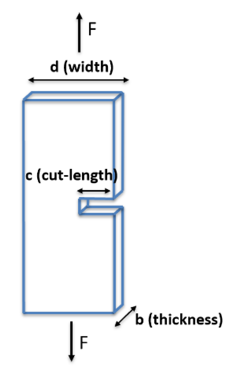
The fracture surface energies were tested by Mode I tensile test using Instron 3345 universal testing machine with a load cell of 500 N. The specimens were 50 mm long and 30 mm, wide with an initial cut of different lengths. Loading the specimens is demonstrated in Figure 1. The specimens were pulled apart at a constant speed of 0.5 mm/min at room temperature.

2.3.2. Electron Microscopy

The quality of dispersion was analyzed by XHRSEM (extra high-resolution scanning microscopy) MagellanTM 400L. The operating voltage and current were 2–5 kV and 50 pA, respectively. The samples were tested after the tensile test using a designated cross-section stub. The samples were coated with a mixture of Au-Pd for 60 s using a SC7640 Sputter.

2.3.3. Dynamic Mechanical Properties

The dynamic mechanical properties were characterized with a dynamic mechanical analyzer (DMA) Q800 V21.3 Build 96 instrument. The test was performed under tensile mode at 1 Hz and −40 °C to 60 °C with heating rate of 5 °C/min.

3. Results

3.1. Mechanical Properties

3.1.1. Fracture Surface Energy of Initiation ( γ I )

The value of γ I may be calculated by different methods [13]. After some trial and error, the energy of initiation, γ I , was calculated from the following equation:
γ I = U I 2 · b · c
where U I is the area under the graph up to the point where the tear starts to propagate (Figure 2a), b is the thickness of the sample, and c is the length of the cut. A graph of γ I versus the cut length shows an exponential trend—this asymptotically converges at higher cut lengths (Figure 2b). The final value is defined as the average value of the energies for cut lengths of 15 mm, 20 mm, and 25 mm (cut length that experiences minimum plastic deformation).
Figure 3 indicates that there are no significant differences between the fracture energies of initiation (γI) among the different samples. The iPP/0.5%-SiO2 has the highest value, while its hybrid composition presents the lowest along with NC. The initial energy is the summed energy up to the point where propagation starts.

3.1.2. Total Energy Dissipated in The Fracture Process ( γ F )

The value of γ F was calculated using the following equation:
γ F = U F 2 · b · ( d c )
where U F is the area under the graph up to the point of total tear (Figure 4a) and d is the width of the sample. A curve with a linear fit was generated from the graph of γ F versus the cut length (Figure 4b). The fracture energy at 25 mm (where the fracture is mainly controlled with fewer catastrophic fractures) was calculated from the linear fitting equation and defined to be the final γ F value. Here, the term “fracture energy” is equivalent to the term “total fracture energy (γF)”.
Unlike the fracture energy of initiation, the fracture energy (γF) has significant differences between the various samples (Figure 5). Here, all composites are improved versus the neat iPP. The hybrid sample of iPP/0.5%-GNP/0.5%-VGCG demonstrates the highest value among all the different samples and therefore expresses a positive hybrid effect. We assume that the variation in the total energy among the different samples results mainly from the required energy for crack propagation, because most of the samples have very similar initial fracture energy. This is an unambiguous indication that the fracture propagation of the hybrid nanocomposite is significantly slowed down. This property is highly important for the fracture resistance of composites, where structures that already contain an initial damage will exhibit controlled crack propagation.

3.2. Morphological Analysis

Cross-section SEM images (Figure 6) of the surface fracture show a surface suitable for fracture mechanism. All surfaces are rough and similar. The qualitative roughness of the composite samples is higher than the roughness of the neat iPP sample. This also has a lower fracture energy. Although only two samples are presented, all samples give similar observations. However, no quantitative measurements were done because this hypothesis has already been discussed in a previous paper [6].
SEM images of cross section were captured after a Mode I tensile test of the samples. A closer look at the neat iPP indicates a stalactite-like shape representing plastic deformation in the tensile direction (Figure 7a). At higher magnifications, a formation of fibrous-like microstructure is seen. These microfibers bridge matrix cracks by the crazing mechanism (Figure 7b), which can reduce the stress at the crack tip by a factor of seven [14].
Figure 8 introduces the cross section of selected nanocomposites with superior properties. The system of iPP/0.5%-GNP that achieved the highest fracture energy among the parent composites demonstrates poor dispersion and large aggregates. However, there is substantial interaction between the polymer and the GNP. In contrast to the GNP, the VGCF are uniformly dispersed in the matrix, and single fibers are observed throughout the sample. The hybrid system also presents well dispersed VGCF alongside poorly dispersed GNP. The SEM images indicate that the GNP are found near the VGCF in the matrix, but the two fillers do not interact directly with each other. The last nanocomposite is iPP/0.5%-SiO2, which also has increased fracture energy. The SEM image of this nanocomposite demonstrates good interactions between the fibers and the matrix—there are smaller aggregates here than are seen in GNP (bundles of a few fibers). The iPP/0.5%-SiO2 material also has pulled out SiO2 fibers. Hence, we see that the two main mechanisms that contribute to the increased fracture energy may exist simultaneously, regardless of the level of dispersion.

3.3. Dynamic Mechanical Properties

DMA results of tanδ for the chosen set (Figure 9) indicates the different behavior of the hybrid sample. The presence of GNP had no real influence on the tanδ, while VGCF decrease its value versus the neat iPP. Such a reduction may result from the restriction of polymer chain mobility by attraction with the nanofiller as described [15]. Unlike the VGCF, the GNP form aggregates, and therefore, have less common surface with polymer chains, and they do not limit the motion to the same extent [16,17,18]. Nevertheless, the contrasting responses of the two fillers lead to the highest ability to absorb energy, expressed in increased damping.

4. Discussion

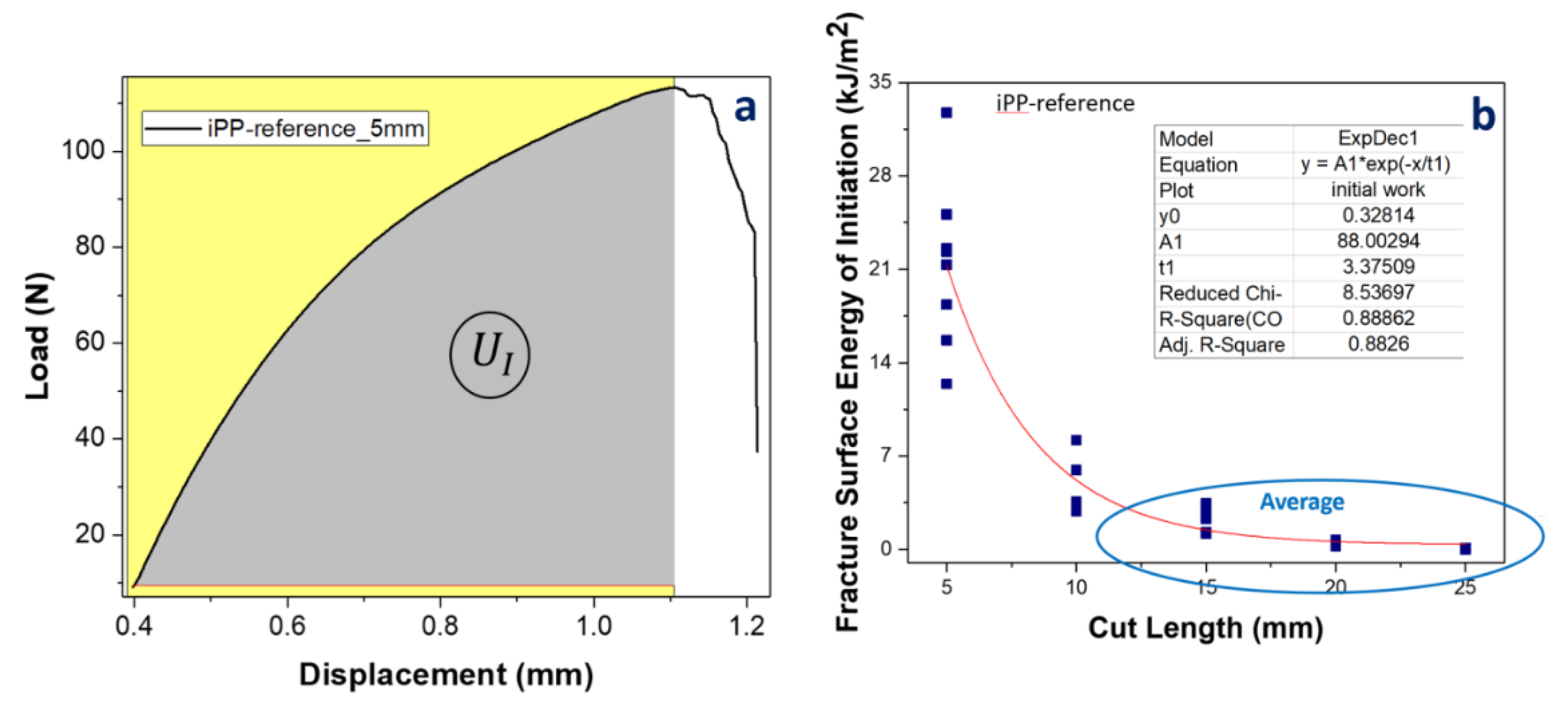
The nature of the fracture process (either controlled or catastrophic) depends on the length of the cut. Samples with lower cut length will experience more controlled fracture, while samples with higher cut length will experience more catastrophic structure. In controlled fracture propagation, all of the invested elastic energy from the tensile is converted to create a new surface during the crack propagation via breaking of the structural bonds. In a catastrophic fracture, the elastic invested energy is much higher than the required energy for surface formation—this excess energy is dissipated as heat, kinetic energy, plastic deformation, etc. A good example of catastrophic failure is glass breakage, in which some of the energy is dissipated via the sound of the breaking glass and not in the creation of a new surface. During crack propagation, a strain energy (proportional to c2, when c is the crack length) from unloaded regions near the crack tip is released. At the same time, energy for bond breakage (proportional to c) is invested. The applied stress increases up to the onset of crack propagation; thereafter, the crack propagates at a constant strain energy release rate at controlled process [19]. The nature of the complete fracture process depends on the initial cut (crack) length changing from catastrophic to controlled for shallower cuts. Theoretically, a complete conversion to fracture surface energy of the strain energy dissipated in the fracture process will occur for a cut length equal to the width of the sample.
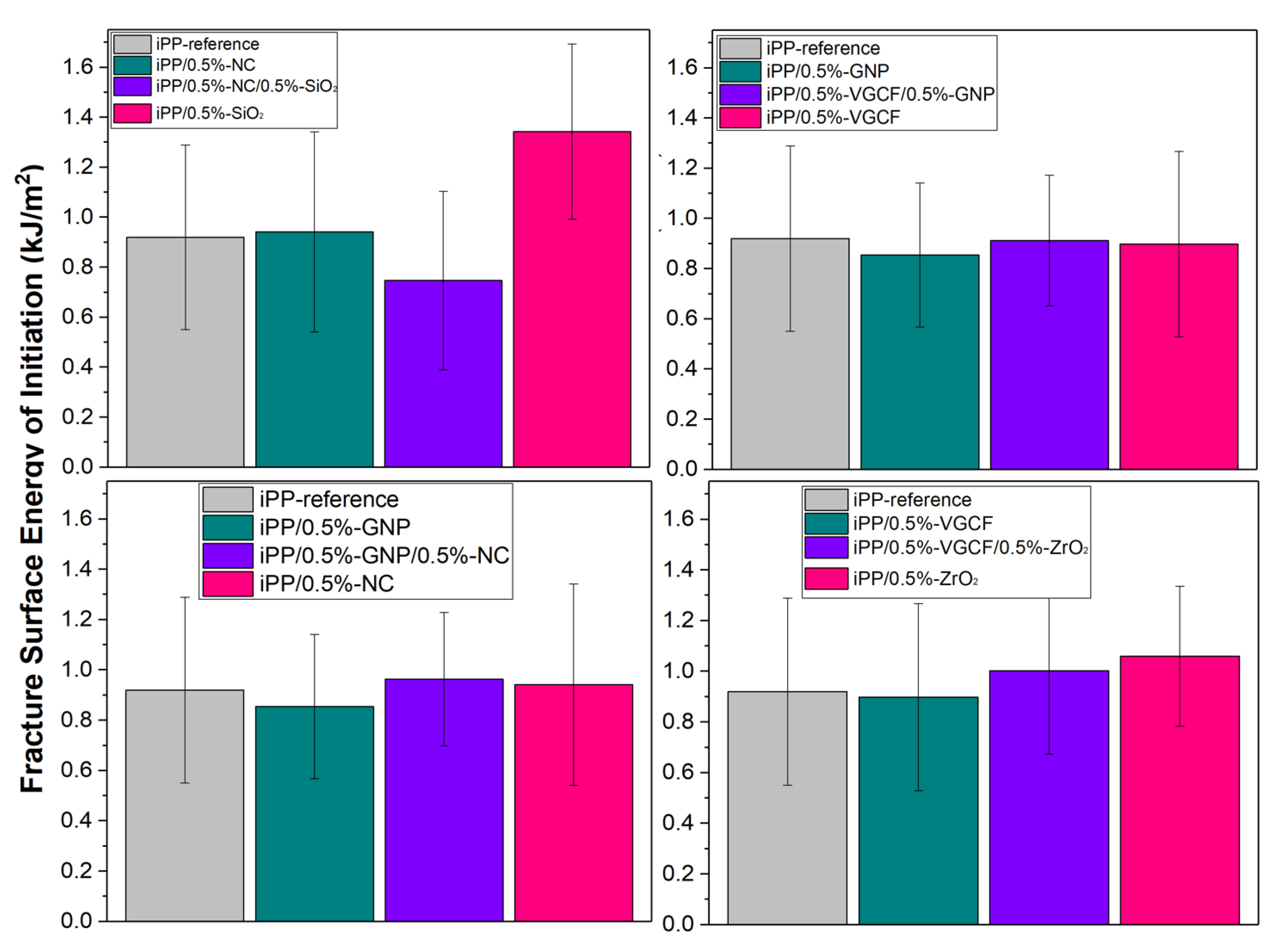
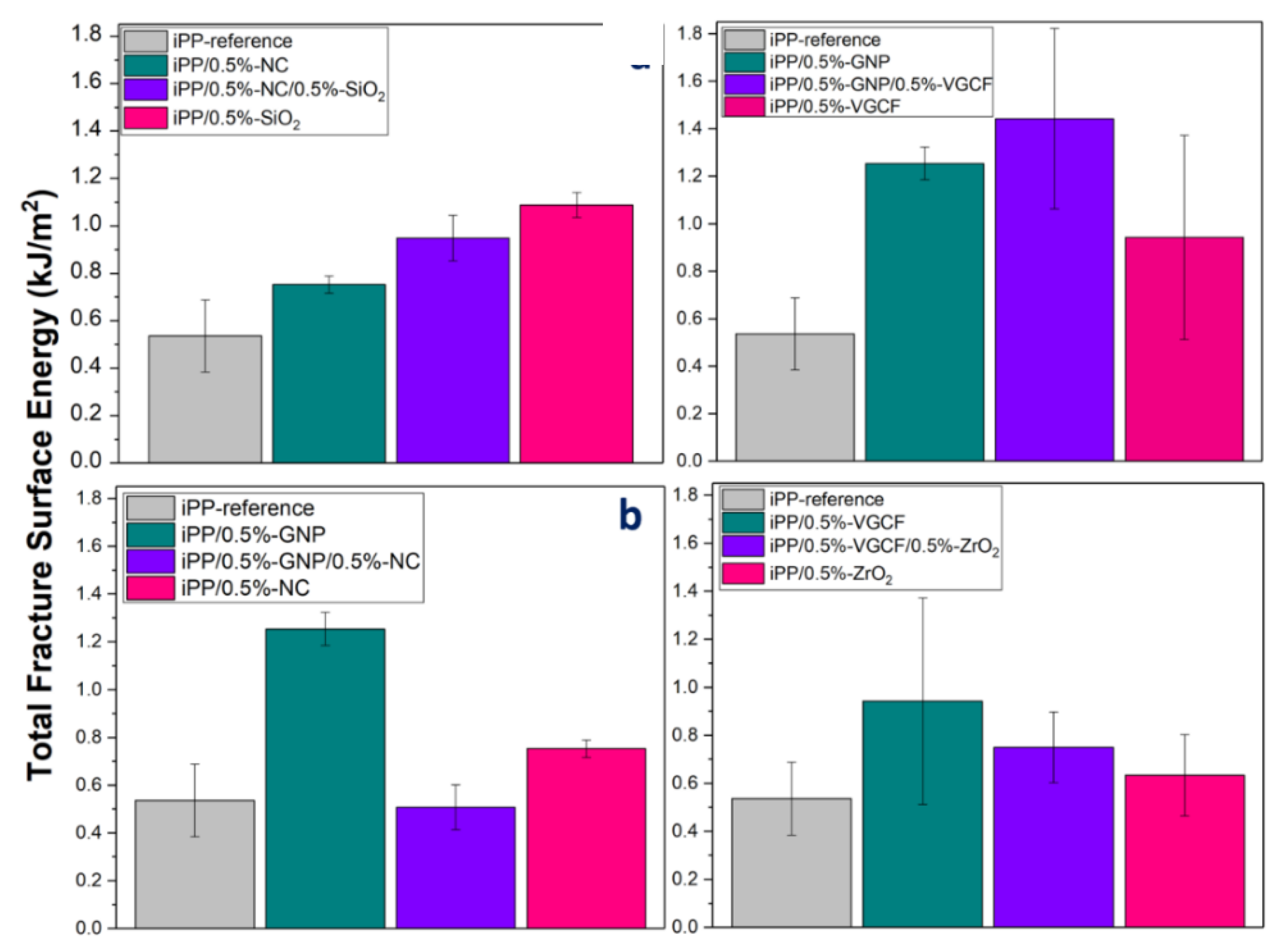
The results indicated that there were no significant differences for γI between the samples, and only one sample (iPP/0.5%-SiO2) exhibited a significantly higher value. This may be attributed to the relatively high fracture surface area of the SiO
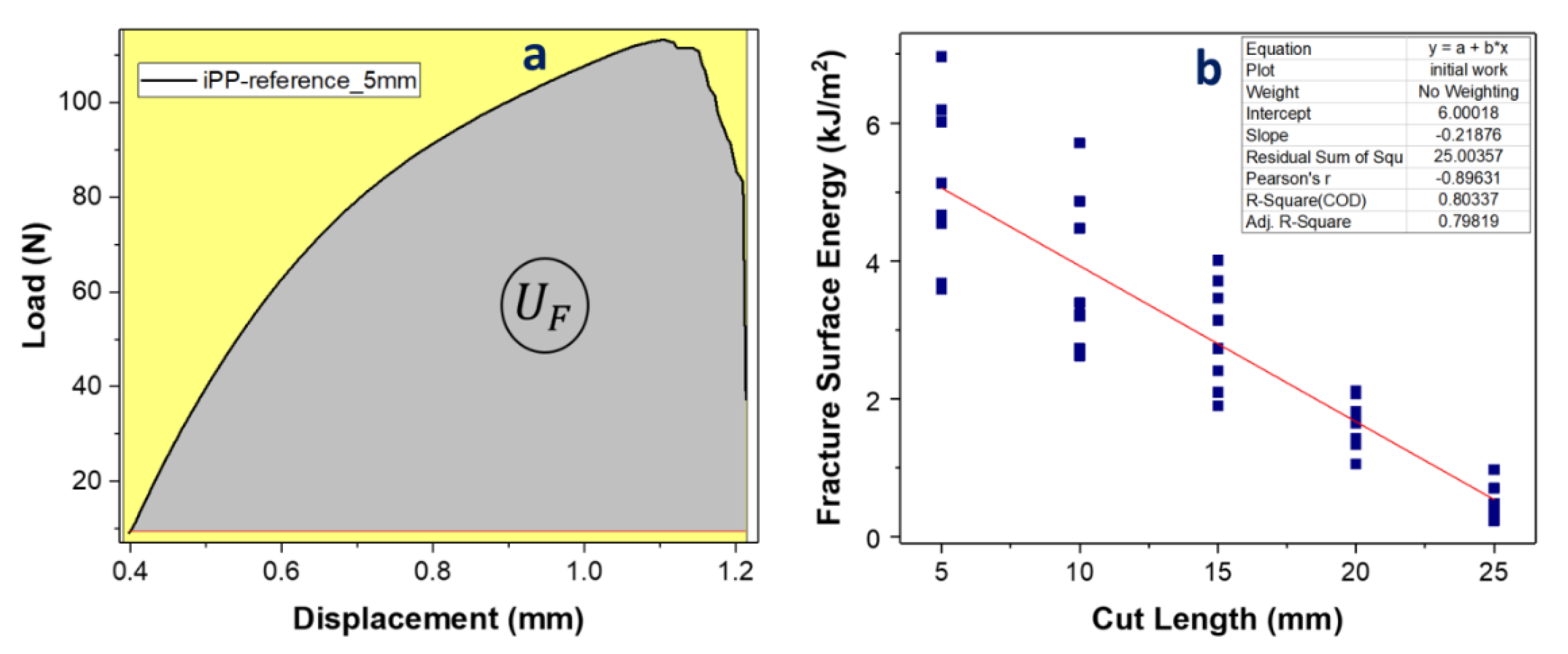
2 nanofibers, which allows the iPP to intercalate in between the nanofibers, leading to better interactions between the filler and the polymer. The fracture energy of initiation is a function of the stored energy up to fracture onset, which in turn depends on the quasistatic mechanical properties (modulus and strength) of the composites. Conversely, for γ
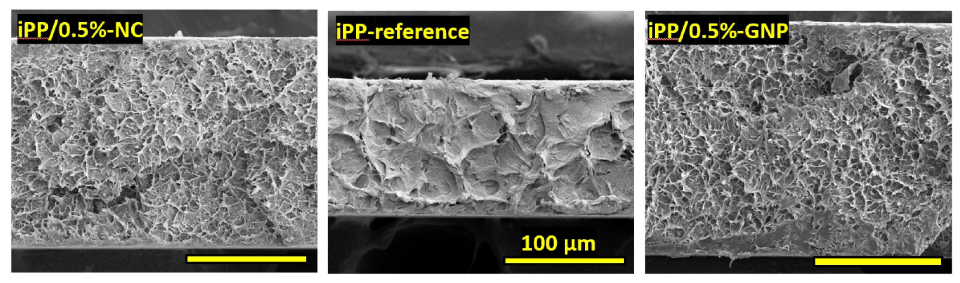
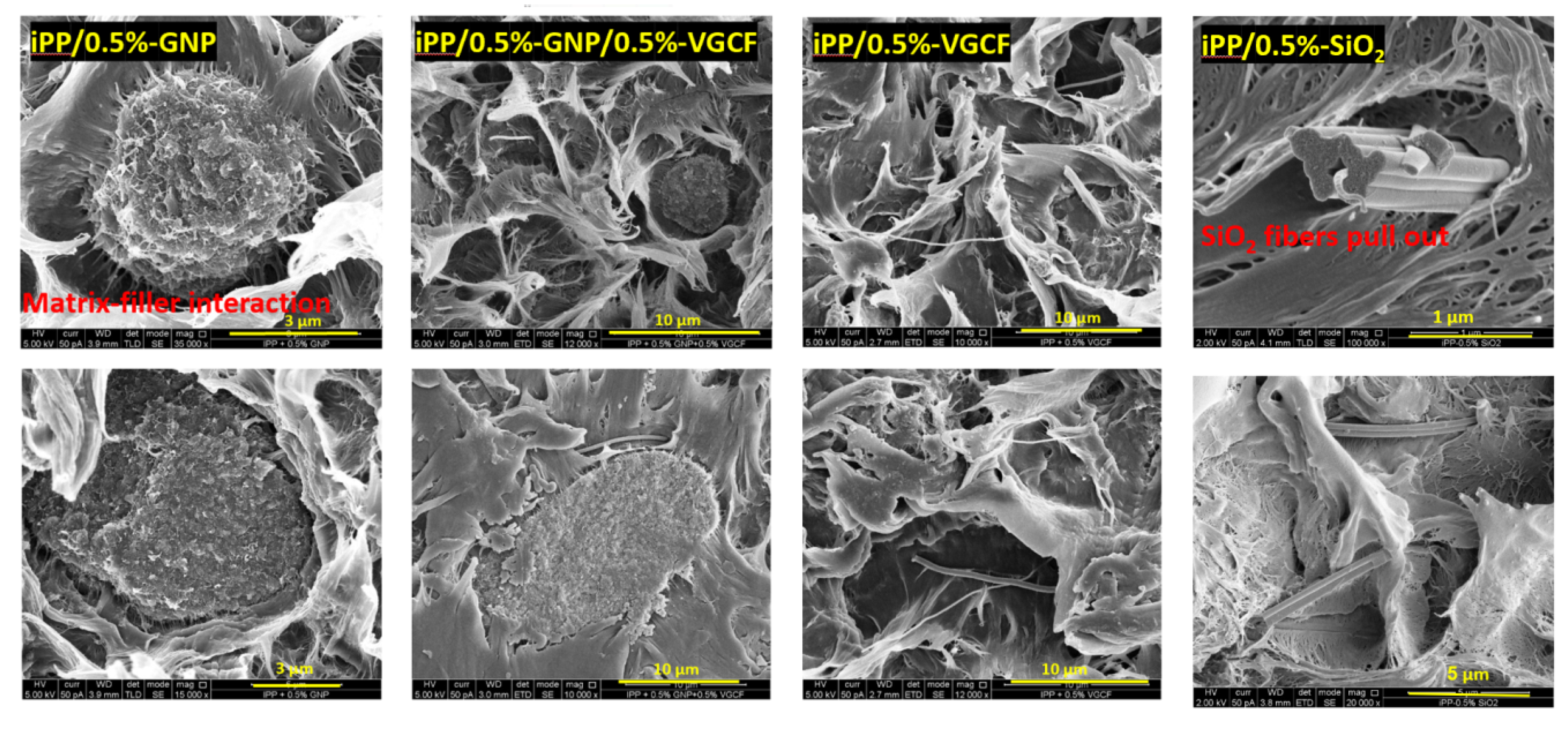
F, all the composite samples reached an enhanced fracture energy, in comparison to the neat iPP, wherein different energies were measured, reflecting their different compositions, geometries, and structures. Considering that all the samples were treated identically, the results and the quality of dispersions were a product of the type of nanoparticle and its interface with iPP. As pointed out in the previous section, SEM analysis (Figure 7) revealed that fibrous nanofillers (VGCF, SiO2, and ZrO2) dispersed better than platelet fillers (GNP, NC). Nevertheless, it seems that the major factor for high fracture energy is the nature of the interactions between the advancing crack-front and the nanoparticles. The iPP/0.5%-GNP nanocomposite, which presented the best nanoparticle (GNP)-iPP affinity, exhibited the highest value of fracture energy regardless of the poor GNP dispersion quality, showing mainly large aggregates. Moreover, the nanohybrid of iPP/0.5%-GNP/0.5%-VGCF reached the highest value relative to all the nanocomposites and thus exhibited a positive hybrid effect. These results stem from the behavior of the respective parent nanocomposites as follows. The iPP/0.5%-VGCF nanocomposite in itself exhibited higher values than the neat iPP, showing the best dispersion of fully exfoliated single nanofibers with no aggregates. These well dispersed individual nanofibers of high aspect ratio could increase the energy by the classical debonding/fiber breakage/pull-out mechanism of fiber reinforced composites [10,20]. Conversely, the iPP/0.5%-GNP nanocomposite contained GNP aggregates of micro dimension, which contributed to the improvement of the fracture energy by the classical mechanism of crack-front pinning at adjacent particles and bowing away from them to increase the crack front surface area [21].
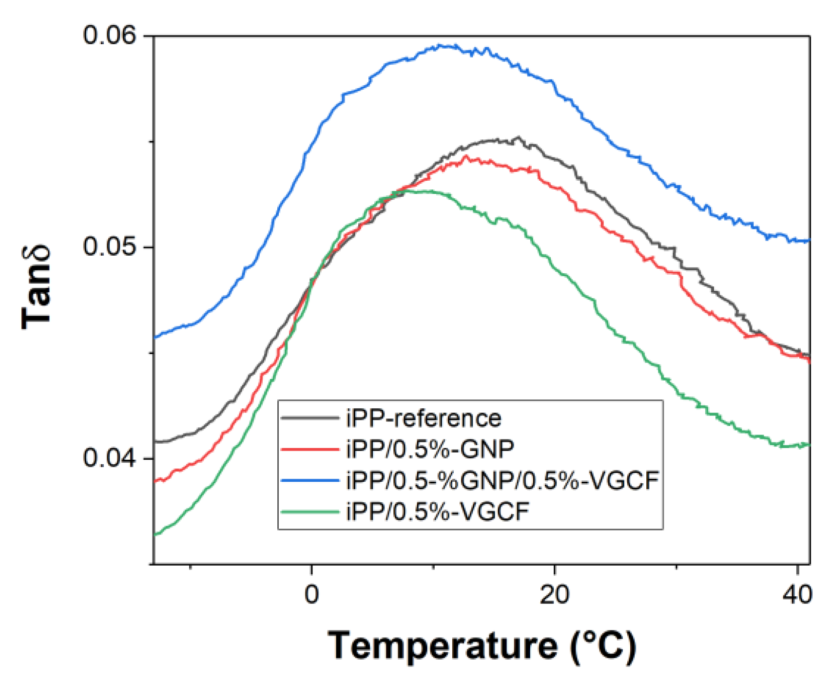
It is noted that the overall content of nanoparticles in the hybrids was twice of those in the parent composites. Yet, we suggest that the significantly high fracture toughness of the nanohybrid in this system may reflect a hybrid effect, wherein the energy dissipation that derives from the simultaneous occurrence of both the crack-front bowing and pull-out mechanisms is higher than the arithmetic sum of the weighted average contributions of the GNP and VGCF alone. This was corroborated by the DMA results showing that the nanohybrid exhibited the highest energy damping capacity by far, which was in agreement with the γF value of this system.
Another system that presented a large fracture energy improvement was the iPP/0.5%-SiO2 nanocomposite, which likewise exhibited a good affinity to the iPP matrix. Both the GNP and the SiO2 nanofibers have high surface areas, which may increase the adhesion with the iPP matrix, and, as a result, activate the mechanism of fracture energy dissipation more effectively.
In summary, the addition of nanoparticles raised the fracture toughness of the iPP matrix in all of the composite systems, regardless of the type of nanoparticle; the quality of the dispersion seemed to play a lesser role in improving toughness. Accordingly, nanoparticles of fibrous geometry presented more uniform dispersions of exfoliated particles than those of the platelet geometries, which generated higher fracture toughness values. Conversely, aggregated GNP nanoparticles produced higher fracture resistance than the individually dispersed VGCF. Apparently, the enhancement of fracture toughness by the nanoparticles is a product of the specific interactions that they generate with the advancing crack front. These interactions, such as fiber pull-out and crack-front pinning and bowing, which leave their marks on the fracture surfaces, depend for each particle on its chemical nature and affinity to the matrix, its physical properties and its geometry.

5. Conclusions

The hybrid effect in nanocomposite hybrid systems in an iPP matrix was studied for different types of fillers and divided by their geometries and chemical structures. A system that contained both GNP and VGCF had a positive hybrid effect both in the total energy of fracture and in the dynamic energy damping of the system. Of the parent composites, the GNP sample exhibited the highest fracture toughness, probably due to the good interaction of the GNP with the polymer. Overall, the fracture energy depends on a set of parameters with an emphasis on the matrix–filler interactions. These interfere with the crack front propagation. Hence, no general rules can be formulated for nanocomposites/hybrids; rather, each system should be examined individually to identify its typical structure and composition-dependent crack front interaction mechanisms.

Author Contributions

Supervision, X.H. and G.M.; Writing—original draft, N.S. All authors have read and agreed to the published version of the manuscript.

Funding

This research was funded by the Ministry of Science and Technology of Israel.

Acknowledgments

Nadya Stern acknowledges the M1 inistry of Science and Technology of Israel for the Shulamit Aloni Scholarship for Advancing Women in Exact Sciences and Engineering. The technical assistance of Evgenia Blayvas of the Unit for Nanoscopic Characterization at The Hebrew University Center for Nanoscience and Nanotechnology is highly appreciated.

Conflicts of Interest

The authors declare no conflict of interest.

References

  1. Wtaife, S.; Shaban, A.; Alsabbagh, A.; Alshammari, E.; Suksawang, N. Effect of Hybrid Discrete Fibers on Mechanical Properties of FRC. IOP Conf. Ser. Mater. Sci. Eng. 2018, 454, 12170. [Google Scholar] [CrossRef] [Green Version]
  2. Chen, R.S.; Amran, N.A.M.; Ahmad, S. Reinforcement effect of nanocomposites with single/hybrid graphene nanoplatelets and magnesium hydroxide. J. Therm. Anal. Calorim. 2019, 137, 79–92. [Google Scholar] [CrossRef]
  3. Shajari, S.; Arjmand, M.; Pawar, S.P.; Sundararaj, U.; Sudak, L.J. Synergistic effect of hybrid stainless steel fiber and carbon nanotube on mechanical properties and electromagnetic interference shielding of polypropylene nanocomposites. Compos. B Eng. 2019, 165, 662–670. [Google Scholar] [CrossRef]
  4. Li, Y.; Yan, T.; Yu, T.; Zheng, L.; Liao, K. Synergistic effect of hybrid carbon nantube–graphene oxide as a nanofiller in enhancing the mechanical properties of PVA composites. J. Mater. Chem. 2011, 21, 10844–10851. [Google Scholar] [CrossRef]
  5. Zakuwan, S.; Ahmad, I. Synergistic Effect of Hybridized Cellulose Nanocrystals and Organically Modified Montmorillonite on κ-Carrageenan Bionanocomposites. Nanomaterials 2018, 8, 874. [Google Scholar] [CrossRef] [PubMed] [Green Version]
  6. Stern, N.; Dyamant, I.; Shemer, E.; Hu, X.; Marom, G. Hybrid effects in the fracture toughness of polyvinyl butyral-based nanocomposites. Nanocomposites 2018, 4, 1–9. [Google Scholar] [CrossRef] [Green Version]
  7. El Miri, N.; El Achaby, M.; Fihri, A.; Larzek, M.; Zahouily, M.; Abdelouahdi, K.; Barakat, A.; Solhy, A. Synergistic effect of cellulose nanocrystals/graphene oxide nanosheets as functional hybrid nanofiller for enhancing properties of PVA nanocomposites. Carbohydr. Polym. 2016, 137, 239–248. [Google Scholar] [CrossRef] [PubMed]
  8. Valentini, L.; Bon, S.B.; López-Manchado, M.A.; Verdejo, R.; Pappalardo, L.; Bolognini, A.; Alvino, A.; Borsini, S.; Berardo, A.; Pugno, N.M. Synergistic effect of graphene nanoplatelets and carbon black in multifunctional EPDM nanocomposites. Compos. Sci. Technol. 2016, 18, 123–130. [Google Scholar] [CrossRef]
  9. Saharudin, M.S.; Atif, R.; Hasbi, S.; Ahmad, M.N. Synergistic effects of halloysite and carbon nanotubes (HNTs+ CNTs) on the mechanical properties of epoxy nanocomposites. Transportation 2019, 2, 3. [Google Scholar] [CrossRef]
  10. Marom, G.; Wagner, H.D. Should polymer nanocomposites be regarded as molecular composites? J. Mater. Sci. 2017, 52, 8357–8361. [Google Scholar] [CrossRef]
  11. Stern, N.; Marom, G.; Zhang, L.; Hu, X. Micromechanics of Nanocomposites. In Comprehensive Composite Materials II; Zweben, C.H., Beaumont, P., Peijs, T., Thostenson, E.T., Eds.; Elsevier: Amsterdam, The Netherlands, 2017; pp. 1–27. [Google Scholar]
  12. Rivlin, R.S.; Thomas, A.G. Rupture of rubber. I. Characteristic energy for tearing. J. Polym. Sci. 1953, 10, 291–318. [Google Scholar]
  13. Marom, G.; Stanford, J.L.; White, E.F. Transverse properties of three-phase composites comprising continuous glass fibre, glass microspheres, and epoxy resin. Br. Polym. J. 1974, 6, 25–37. [Google Scholar] [CrossRef]
  14. Friis, E.A.; Hahn, D.L.; Cooke, F.W.; Hooper, S.J. Modeling crack extension in chopped-fiber composites. In Composite Materials: Fatigue and Fracture; ASTM International: Montgomery, PA, USA, 1997. [Google Scholar]
  15. Patel, R.K.; Bhattacharya, B.; Basu, S. Effect of interphase properties on the damping response of polymer nano-composites. Mech. Res. Commun. 2008, 35, 115–125. [Google Scholar] [CrossRef]
  16. Al-Sagheer, F.A.; Merchant, S. Visco-elastic properties of chitosan–titania nano-composites. Carbohydr. Polym. 2011, 85, 356–362. [Google Scholar] [CrossRef]
  17. Hamming, L.M.; Qiao, R.; Messersmith, P.B.; Brinson, L.C. Effects of dispersion and interfacial modification on the macroscale properties of TiO2 polymer–matrix nanocomposites. Compos. Sci. Technol. 2009, 69, 1880–1886. [Google Scholar] [CrossRef] [PubMed] [Green Version]
  18. Ramanathan, T.; Stankovich, S.; Dikin, D.A.; Liu, H.; Shen, H.; Nguyen, S.T.; Brinson, L.C. Graphitic nanofillers in PMMA nanocomposites—An investigation of particle size and dispersion and their influence on nanocomposite properties. J. Polym. Sci. B Polym. Phys. 2007, 45, 2097–2112. [Google Scholar] [CrossRef]
  19. Roylance, D. Introduction to Fracture Mechanics; Massachusetts Institute of Technology: Cambridge, MA, USA, 2001. [Google Scholar]
  20. Chawla, K.K. Metal Matrix Composites; Springer: New York, NY, USA, 2006. [Google Scholar]
  21. Lange, F. The interaction of a crack front with a second-phase dispersion. Philos. Mag. 1970, 22, 983–992. [Google Scholar] [CrossRef]
Figure 1. The geometry of the Mode I test specimen [12].
Jcs 04 00024 g001
Figure 2. (a) Typical load displacement curve denoting the area of UI and (b) a plot of the fracture surface energy of initiation vs. the cut length, marking the regime where the average value was calculated.
Jcs 04 00024 g002
Figure 3. Fracture surface energies of initiation (γI) for all the nanocomposites. Each value is an average of at least seven measurements, showing the average standard deviations.
Jcs 04 00024 g003
Figure 4. (a) Typical load displacement denoting the area of UF for the complete fracture and (b) a plot of the total fracture surface energy vs. the cut length, presenting the linear regression fit from which γF was calculated (for iPP-reference).
Jcs 04 00024 g004
Figure 5. Total fracture surface energies (γF) for all the nanocomposites. Each value is an average of at least seven measurements, showing the standard deviations.
Jcs 04 00024 g005
Figure 6. SEM images of cross sections of the fracture surfaces, demonstrating significant levels of roughness.
Jcs 04 00024 g006
Figure 7. SEM images of iPP cross-sections after Mode I tensile testing at different magnifications. (a) Plastic deformation of stretched polymer at 10,000× magnitude and (b) crazing of the polymer at 50,000X magnitude. The dashed red circles show areas of crack bridging by microfibers.
Jcs 04 00024 g007
Figure 8. SEM images of nanocomposite cross-sections after mode I tensile. From left to right: iPP/0.5%-GNP, iPP/0.5%-GNP/0.5%-VGCF, iPP/0.5%-VGCF, and iPP/0.5%-SiO2.
Jcs 04 00024 g008
Figure 9. Dynamic mechanical analysis energy dissipation results of one hybrid nanocomposite system.
Jcs 04 00024 g009

