A Family of C0 Quadrilateral Plate Elements Based on the Refined Zigzag Theory for the Analysis of Thin and Thick Laminated Composite and Sandwich Plates


Abstract
1. Introduction
2. Theoretical Basis of Refined Zigzag Theory (RZT) and Finite Element Modeling
2.1. Virtual Work Principle and Discretized Equations of Motion
2.1.1. Virtual Variation of the Strain Energy,
2.1.2. Virtual Variation of the Inertia Forces,
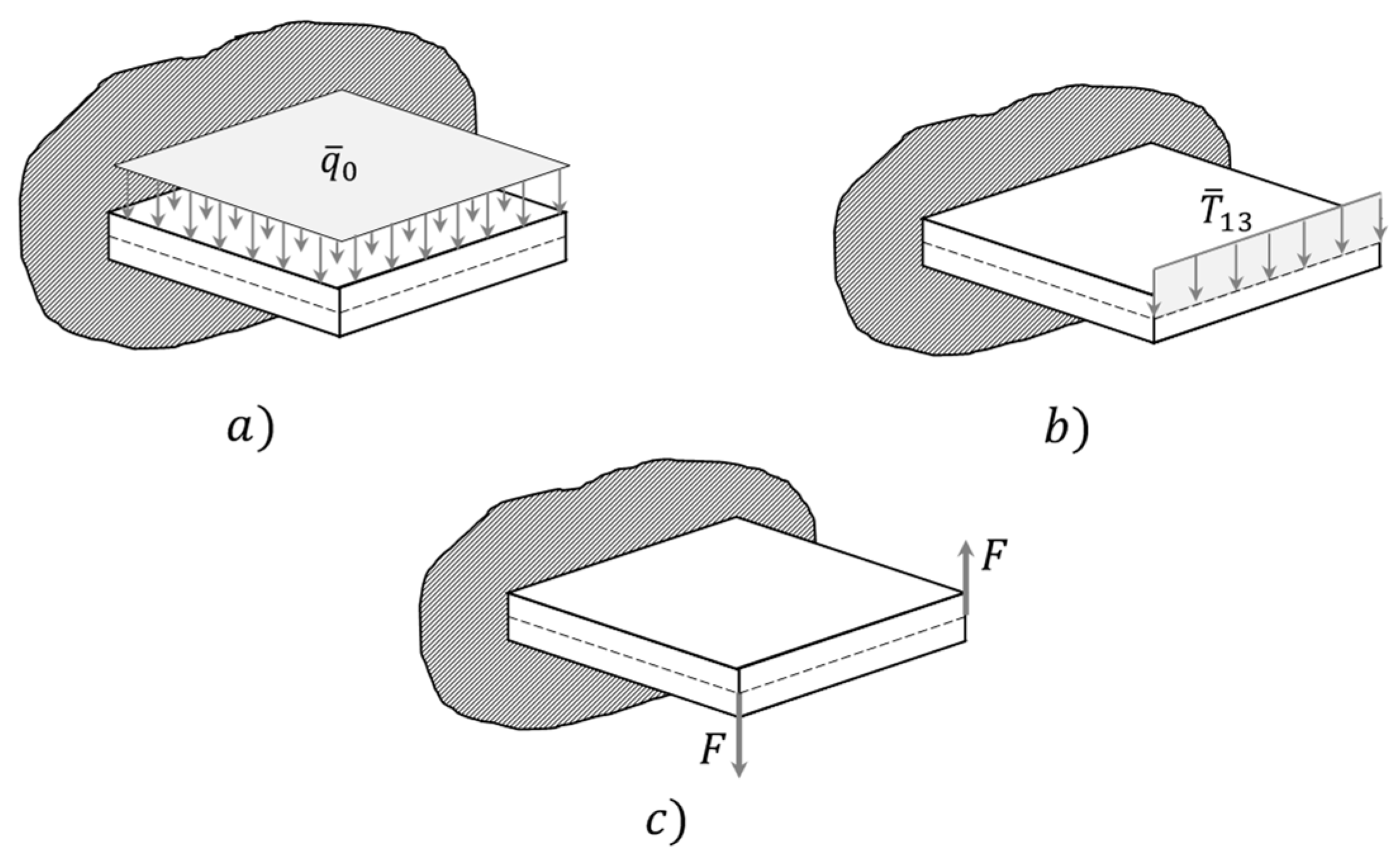
2.1.3. Virtual Variation of the Work of Applied Forces,
3. Finite Element Formulation
3.1. General Equation
3.2. Shape Functions and Constrained Technique
Constrained Technique
4. Numerical Results
4.1. RZT Analytical Performances
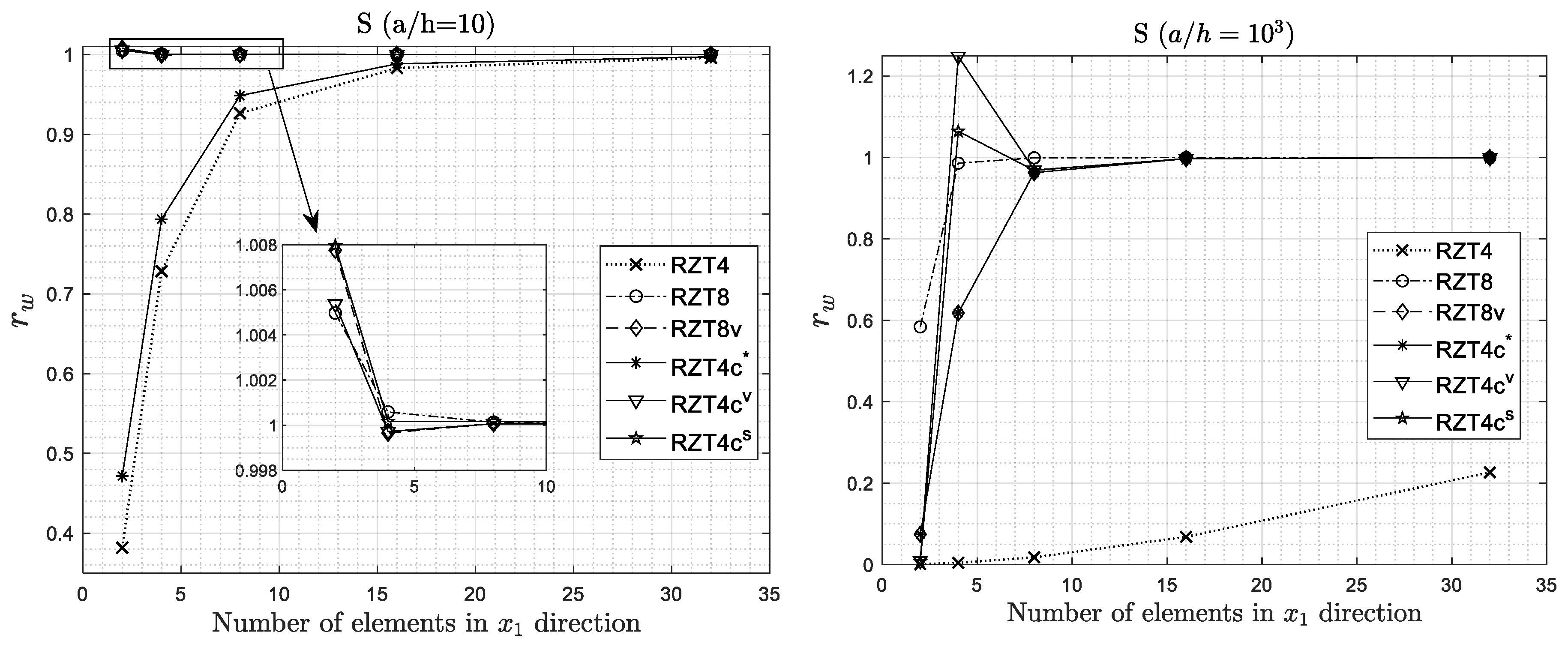
4.2. Convergence Analysis
4.3. Effect of Non-Dimensional Transverse Shear Parameters
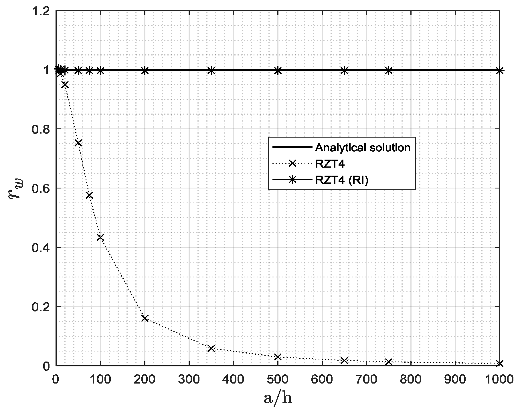
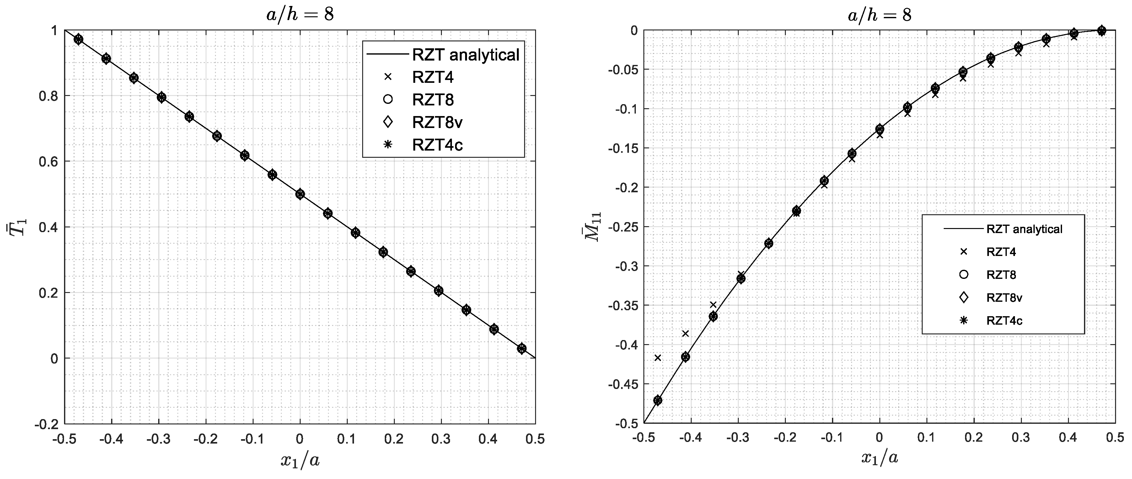
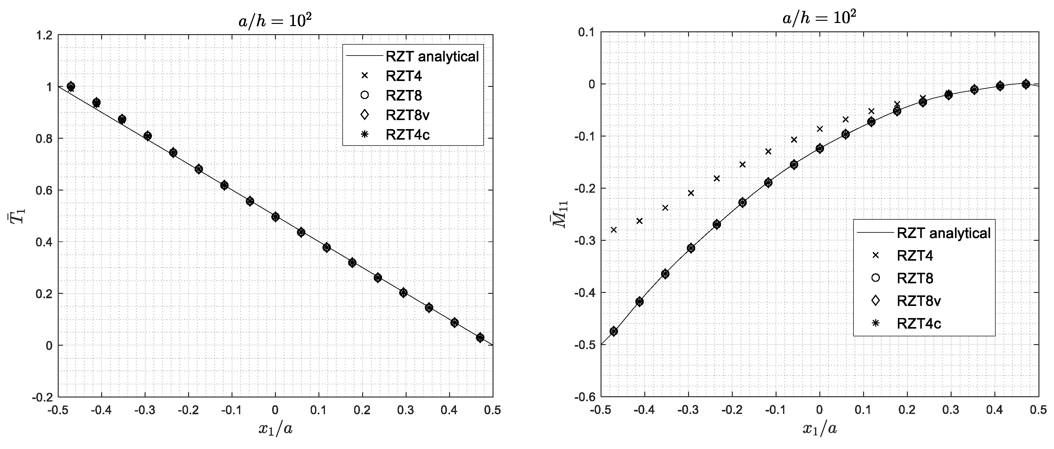
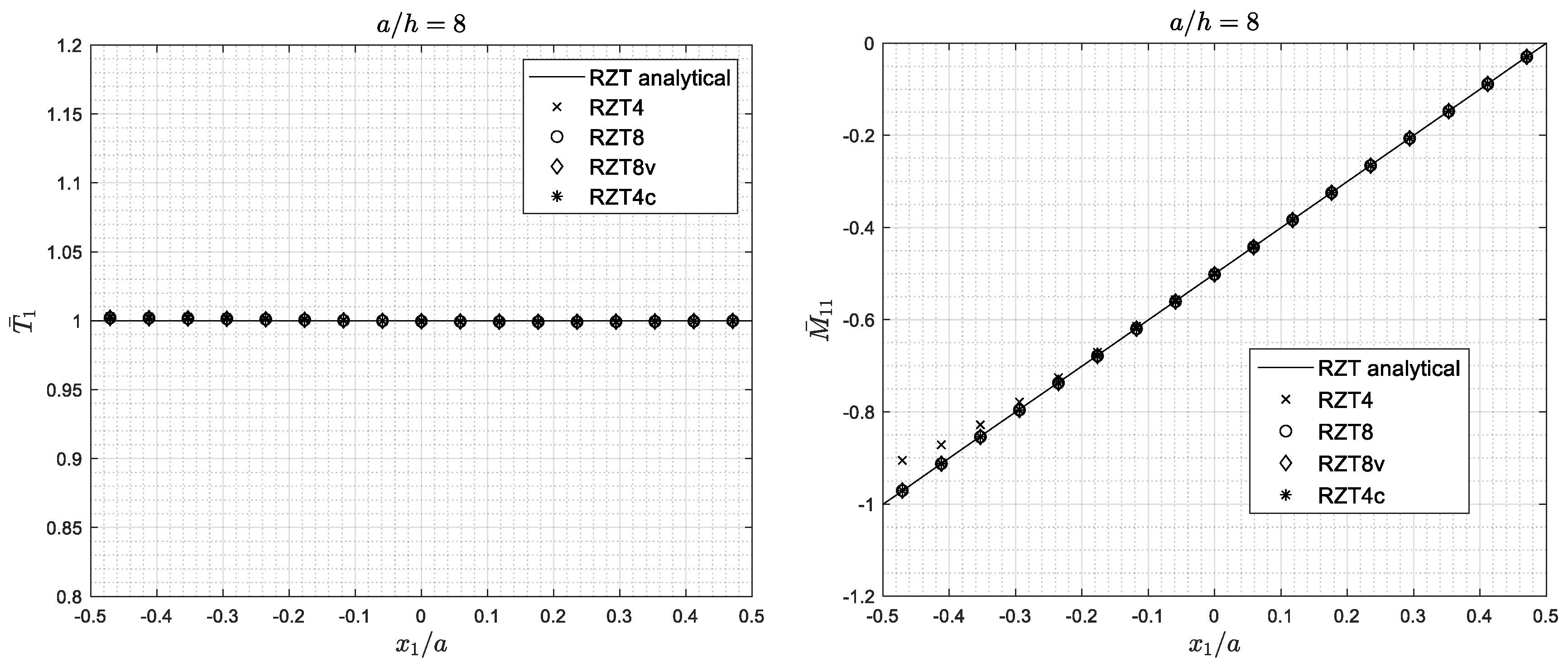
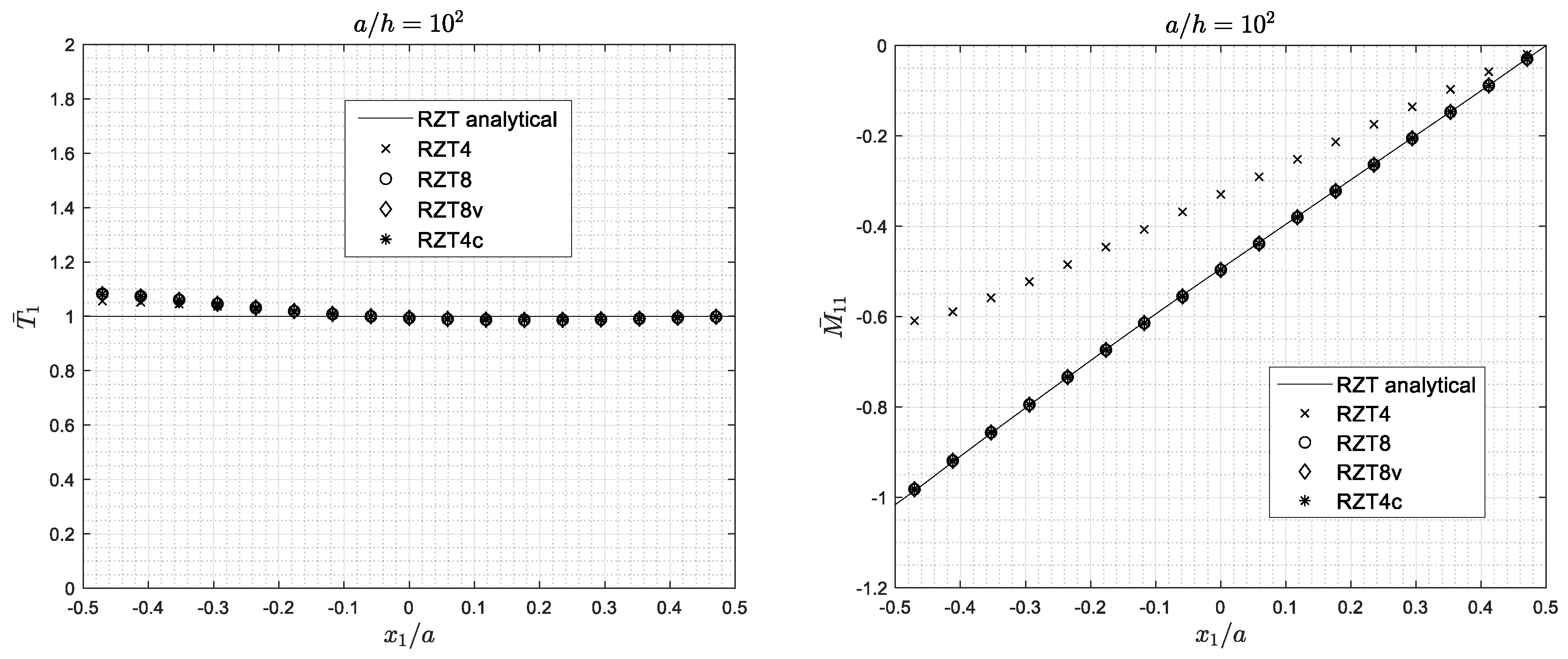
4.4. Shear Locking Phenomenon
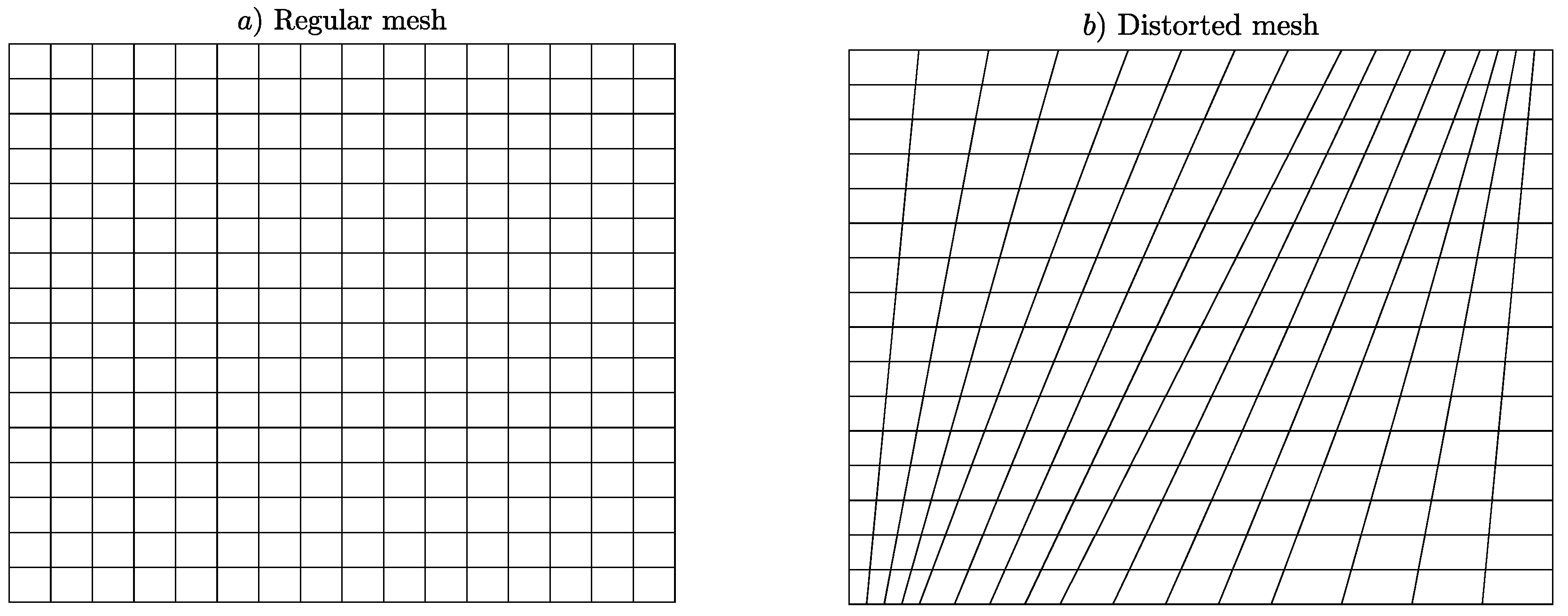
4.5. Distorted and Regular Mesh Analysis
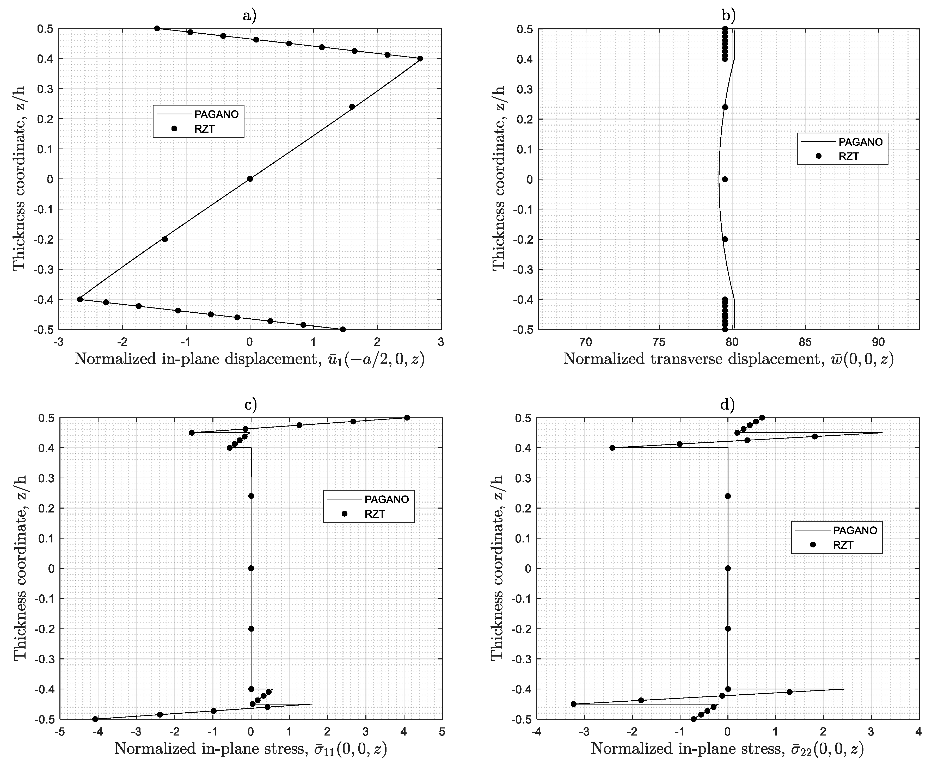
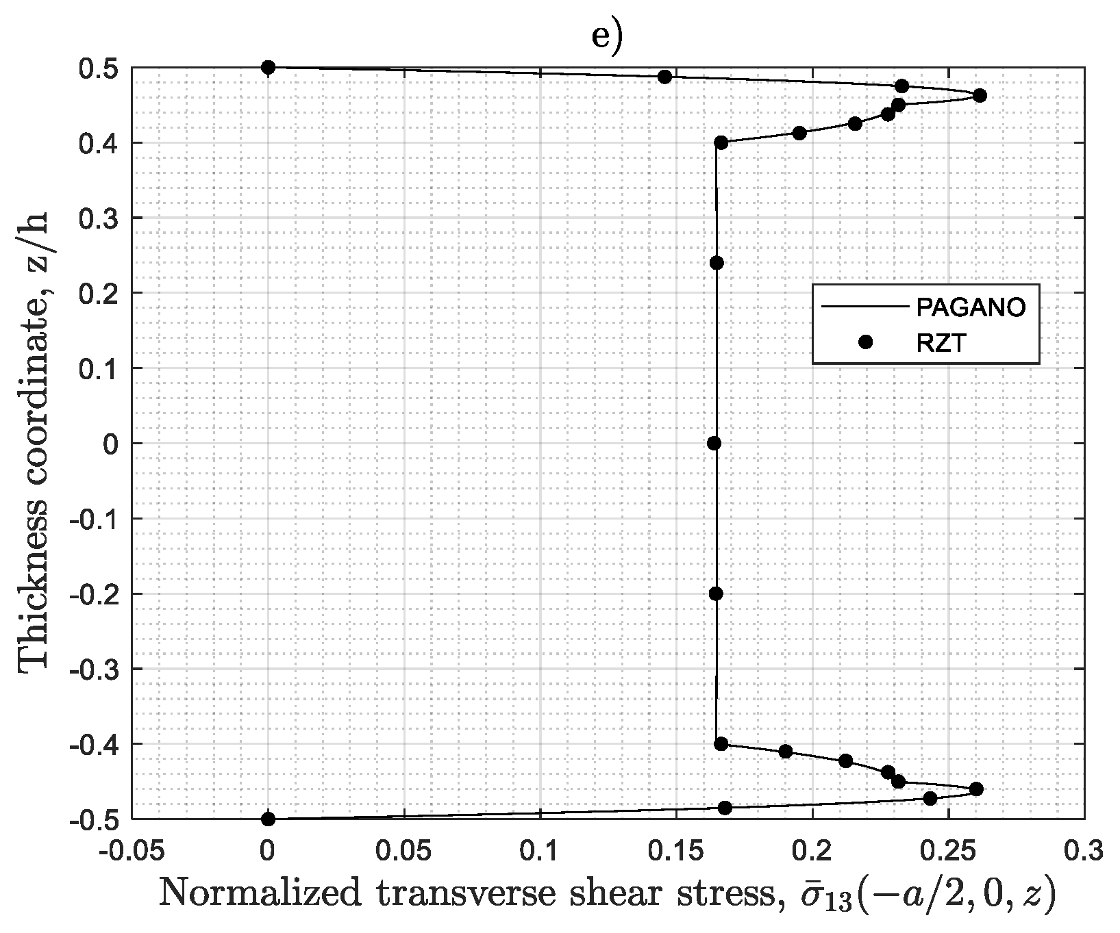
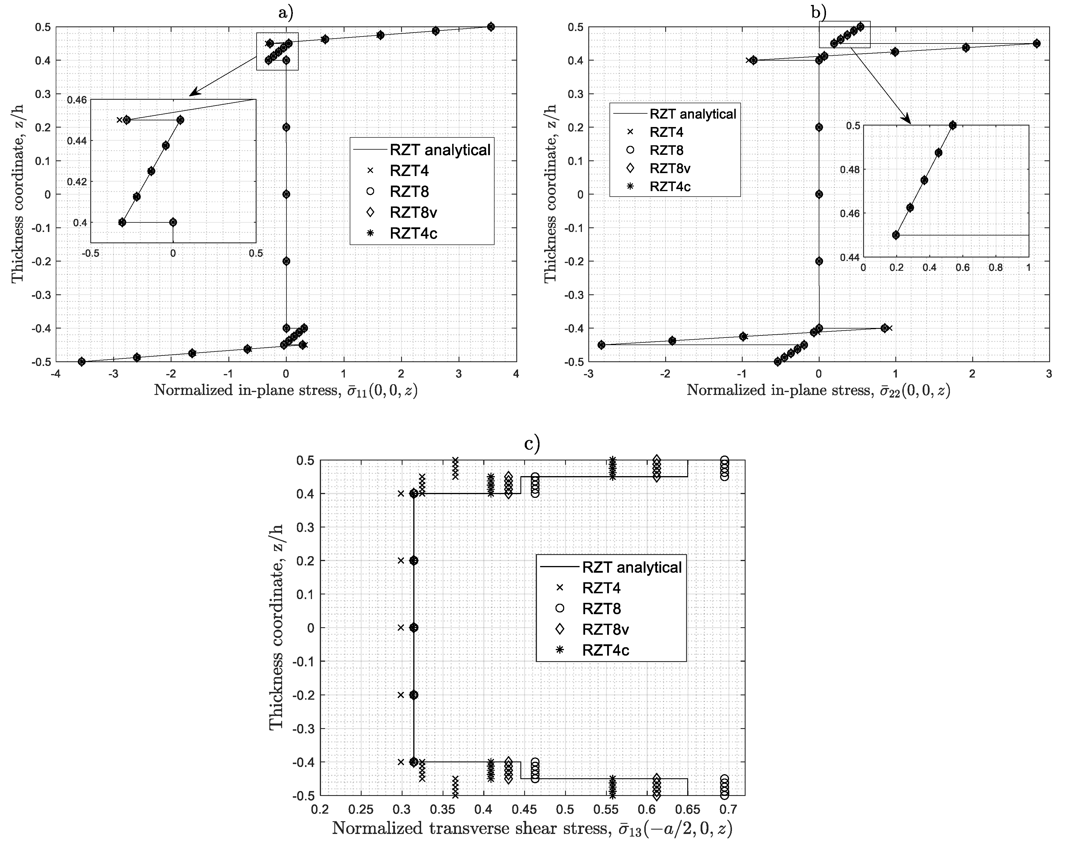
4.6. Stress Distributions
5. Concluding Remarks
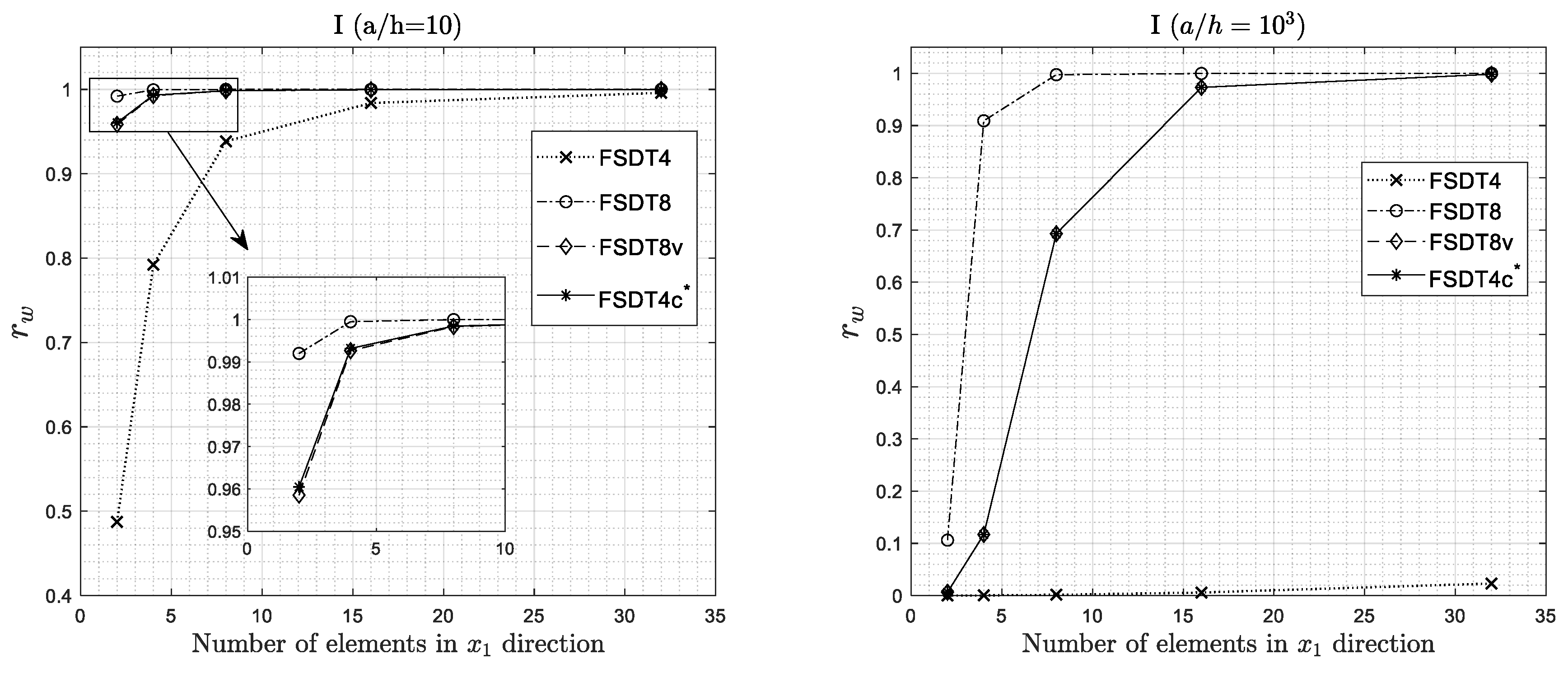
- The convergence of the FEM solution for all the elements of the family is in general monotonic in character, although with different rates.
- The bi-linear 4-node element (RZT4) is strongly affected by the shear locking effect in thin plates when full integration is used.
- The bi-linear 4-node element (RZT4) has performances comparable to the other elements in the range of thin plates when reduced integration (RI) is adopted, but presents extra zero strain energy modes, if no stabilization technique is used.
- The serendipity 8-node element (RZT8), the virgin 8-node element (RZT8v), and the 4-node anisoparametric constrained element (RZT4c) show good performance and predictive capabilities for various problems, and the transverse shear-locking is greatly relieved without using any reduced integration schemes, for thin plate (aspect ratio equal to 5 × 10²) at least for mesh 8 × 8.
- All elements, except for the conventional bi-linear RZT4 element with full integration, are adequate to predict the bending global response (transverse displacement, distribution of the transverse shear resultant, and bending moment) and undamped frequencies. The same holds for the predictive capabilities of the local behaviour (thickness-wise distributions of the bending stresses and transverse shear stresses).
- RZT4c has well-conditioned element stiffness matrix, contrary to RZT4 when reduced integration strategy is used.
- The computational cost of RTZ4c is much lower than that of RTZ8 and RTZ8v elements.
- The accuracy of all the elements is sensitive to their degree of planform distortion.
Author Contributions
Funding
Acknowledgments
Conflicts of Interest
References
- Abrate, S.; di Sciuva, M. Equivalent single layer theories for composite and sandwich structures: A review. Compos. Struct. 2017, 179, 482–494. [Google Scholar] [CrossRef]
- Abrate, S.; di Sciuva, M. Multilayer models for composite and sandwich structures. In Comprehensive Composite Materials II; Beaumont, P.W.R., Zweben, C.H., Eds.; Elsevier: Amsterdam, The Netherlands, 2018; pp. 399–425. ISBN 978-0-08-100534-7. [Google Scholar]
- Whitney, J.M.; Pagano, N.J. Shear deformation in heterogeneous anisotropic plates. J. Appl. Mech. 1970, 37, 1031–1036. [Google Scholar] [CrossRef]
- Reddy, J.N. Mechanics of Laminated Composite Plates and Shells: Theory and Analysis, 2nd ed.; CRC Press: Boca Raton, FL, USA, 2003; ISBN 978-0-203-50280-8. [Google Scholar]
- Pandya, B.N.; Kant, T. Finite element analysis of laminated composite plates using a higher-order displacement model. Compos. Sci. Technol. 1988, 32, 137–155. [Google Scholar] [CrossRef]
- Zhang, Y.X.; Yang, C.H. Recent developments in finite element analysis for laminated composite plates. Compos. Struct. 2009, 88, 147–157. [Google Scholar] [CrossRef]
- Dau, F.; Polit, O.; Touratier, M. An efficient C1 finite element with continuity requirements for multilayered/sandwich shell structures. Comput. Struct. 2004, 82, 1889–1899. [Google Scholar] [CrossRef]
- Dau, F.; Polit, O.; Touratier, M. C1 plate and shell finite elements for geometrically nonlinear analysis of multilayered structures. Comput. Struct. 2006, 84, 1264–1274. [Google Scholar] [CrossRef]
- Polit, O.; Vidal, P.; D’Ottavio, M. Robust C0 high-order plate finite element for thin to very thick structures: Mechanical and thermo-mechanical analysis. Int. J. Numer. Methods Eng. 2012, 90, 429–451. [Google Scholar] [CrossRef]
- Reddy, J.N. A generalization of two-dimensional theories of laminated composite plates. Commun. Appl. Numer. Methods 1987, 3, 173–180. [Google Scholar] [CrossRef]
- Reddy, J.N. An evaluation of equivalent-single-layer and layerwise theories of composite laminates. Compos. Struct. 1993, 25, 21–35. [Google Scholar] [CrossRef]
- Guo, Y.; Nagy, A.P.; Gürdal, Z. A layerwise theory for laminated composites in the framework of isogeometric analysis. Compos. Struct. 2014, 107, 447–457. [Google Scholar] [CrossRef]
- Liu, B.; Ferreira, A.J.M.; Xing, Y.F.; Neves, A.M.A. Analysis of composite plates using a layerwise theory and a differential quadrature finite element method. Compos. Struct. 2016, 156, 393–398. [Google Scholar] [CrossRef]
- Di Sciuva, M. Bending, vibration and buckling of simply supported thick multilayered orthotropic plates: An evaluation of a new displacement model. J. Sound Vib. 1986, 105, 425–442. [Google Scholar] [CrossRef]
- Di Sciuva, M. An improved shear-deformation theory for moderately thick multilayered anisotropic shells and plates. J. Appl. Mech. 1987, 54, 589–596. [Google Scholar] [CrossRef]
- Di Sciuva, M. Multilayered anisotropic plate models with continuous interlaminar stresses. Compos. Struct. 1992, 22, 149–167. [Google Scholar] [CrossRef]
- Di Sciuva, M. Development of an anisotropic, multilayered, shear-deformable rectangular plate element. Comput. Struct. 1985, 21, 789–796. [Google Scholar] [CrossRef]
- Di Sciuva, M. Evaluation of some multilayered, shear-deformable plate elements. Comput. Struct. 1986, 24, 845–854. [Google Scholar] [CrossRef]
- Di Sciuva, M. A general quadrilateral multilayered plate element with continuous interlaminar stresses. Comput. Struct. 1993, 47, 91–105. [Google Scholar] [CrossRef]
- Di Sciuva, M. A third-order triangular multilayered plate finite element with continuous interlaminar stresses. Int. J. Numer. Methods Eng. 1995, 38, 1–26. [Google Scholar] [CrossRef]
- Tessler, A.; di Sciuva, M.; Gherlone, M. Refinement of Timoshenko Beam Theory for Composite and Sandwich Beams Using Zigzag Kinematics; NASA/TP-2007-215086; NASA Langley Research Center: Hampton, VA, USA, 2007; pp. 1–45.
- Tessler, A.; di Sciuva, M.; Gherlone, M. Refined Zigzag Theory for Laminated Composite and Sandwich Plates; NASA/TP-2009-215561; NASA Langley Research Center: Hampton, VA, USA, 2009; pp. 1–53.
- Tessler, A.; di Sciuva, M.; Gherlone, M. A refined zigzag beam theory for composite and sandwich beams. J. Compos. Mater. 2009, 43, 1051–1081. [Google Scholar] [CrossRef]
- Iurlaro, L.; Gherlone, M.; di Sciuva, M.; Tessler, A. Assessment of the refined zigzag theory for bending, vibration, and buckling of sandwich plates: A comparative study of different theories. Compos. Struct. 2013, 106, 777–792. [Google Scholar] [CrossRef]
- Gherlone, M. On the use of zigzag functions in equivalent single layer theories for laminated composite and sandwich beams: A comparative study and some observations on external weak layers. J. Appl. Mech. 2013, 80, 061004. [Google Scholar] [CrossRef]
- Gherlone, M.; Tessler, A.; di Sciuva, M. C0 beam elements based on the refined zigzag theory for multilayered composite and sandwich laminates. Compos. Struct. 2011, 93, 2882–2894. [Google Scholar] [CrossRef]
- Oñate, E.; Eijo, A.; Oller, S. Simple and accurate two-noded beam element for composite laminated beams using a refined zigzag theory. Comput. Methods Appl. Mech. Eng. 2012, 213–216, 362–382. [Google Scholar] [CrossRef]
- Versino, D.; Gherlone, M.; Mattone, M.C.; di Sciuva, M.; Tessler, A. C0 triangular elements based on the refined zigzag theory for multilayered composite and sandwich plates. Compos. Part B Eng. 2013, 44, 218–230. [Google Scholar] [CrossRef]
- Eijo, A.; Oñate, E.; Oller, S. A four-noded quadrilateral element for composite laminated plates/shells using the refined zigzag theory. Int. J. Numer. Methods Eng. 2013, 95, 631–660. [Google Scholar] [CrossRef]
- Eijo, A.; Oñate, E.; Oller, S. A numerical model of delamination in composite laminated beams using the LRZ beam element based on the refined zigzag theory. Compos. Struct. 2013, 104, 270–280. [Google Scholar] [CrossRef]
- Eijo, A.; Oñate, E.; Oller, S. Delamination in laminated plates using the 4-noded quadrilateral QLRZ plate element based on the refined zigzag theory. Compos. Struct. 2014, 108, 456–471. [Google Scholar] [CrossRef]
- Versino, D.; Gherlone, M.; di Sciuva, M. Four-node shell element for doubly curved multilayered composites based on the refined zigzag theory. Compos. Struct. 2014, 118, 392–402. [Google Scholar] [CrossRef]
- Treviso, A.; Mundo, D.; Tournour, M. A C0-continuous RZT beam element for the damped response of laminated structures. Compos. Struct. 2015, 131, 987–994. [Google Scholar] [CrossRef]
- Di Sciuva, M.; Gherlone, M.; Iurlaro, L.; Tessler, A. A class of higher-order C0 composite and sandwich beam elements based on the refined zigzag theory. Compos. Struct. 2015, 132, 784–803. [Google Scholar] [CrossRef]
- Groh, R.M.J.; Weaver, P.M. On displacement-based and mixed-variational equivalent single layer theories for modelling highly heterogeneous laminated beams. Int. J. Solids Struct. 2015, 59, 147–170. [Google Scholar] [CrossRef]
- Iurlaro, L. Development of Refined Models for Multilayered Composite and Sandwich Structures: Analytical Formulation, FEM Implementation and Experimental Assessment. Ph.D. Thesis, Politecnico di Torino, Torino, Italy, 2015. [Google Scholar]
- Treviso, A.; Mundo, D.; Tournour, M. Dynamic response of laminated structures using a refined zigzag theory shell element. Compos. Struct. 2017, 159, 197–205. [Google Scholar] [CrossRef]
- Oñate, E. Structural Analysis with the Finite Element Method. Linear Statics: Volume 2: Beams, Plates and Shells; Lecture Notes on Numerical Methods in Engineering and Sciences; Springer: Dordrecht, The Netherlands, 2013; ISBN 978-1-4020-8742-4. [Google Scholar]
- Babuška, I.; Suri, M. Locking effects in the finite element approximation of elasticity problems. Numer. Math. 1992, 62, 439–463. [Google Scholar] [CrossRef]
- Babuška, I.; Suri, M. On locking and robustness in the finite element method. SIAM J. Numer. Anal. 1992, 29, 1261–1293. [Google Scholar] [CrossRef]
- Barut, A.; Madenci, E.; Tessler, A. Nonlinear analysis of laminates through a mindlin-type shear deformable shallow shell element. Comput. Methods Appl. Mech. Eng. 1997, 143, 155–173. [Google Scholar] [CrossRef]
- Barut, A.; Madenci, E.; Tessler, A. Nonlinear thermoelastic analysis of composite panels under non-uniform temperature distribution. Int. J. Solids Struct. 2000, 37, 3681–3713. [Google Scholar] [CrossRef]
- Zienkiewicz, O.C.; Taylor, R.L.; Too, J.M. Reduced integration technique in general analysis of plates and shells. Int. J. Numer. Methods Eng. 1971, 3, 275–290. [Google Scholar] [CrossRef]
- Hughes, T.J.R.; Taylor, R.L.; Kanoknukulchai, W. A simple and efficient finite element for plate bending. Int. J. Numer. Methods Eng. 1977, 11, 1529–1543. [Google Scholar] [CrossRef]
- Pugh, E.D.L.; Hinton, E.; Zienkiewicz, O.C. A study of quadrilateral plate bending elements with ‘reduced’ integration. Int. J. Numer. Methods Eng. 1978, 12, 1059–1079. [Google Scholar] [CrossRef]
- Hughes, T.J.R.; Cohen, M.; Haroun, M. Reduced and selective integration techniques in the finite element analysis of plates. Nucl. Eng. Des. 1978, 46, 203–222. [Google Scholar] [CrossRef]
- Stricklin, J.A.; Haisler, W.E.; Tisdale, P.R.; Gunderson, R. A rapidly converging triangular plate element. AIAA J. 1969, 7, 180–181. [Google Scholar] [CrossRef]
- Batoz, J.-L.; Bathe, K.-J.; Ho, L.-W. A study of three-node triangular plate bending elements. Int. J. Numer. Methods Eng. 1980, 15, 1771–1812. [Google Scholar] [CrossRef]
- Dvorkin, E.N.; Bathe, K. A continuum mechanics based four-node shell element for general non-linear analysis. Eng. Comput. 1984, 1, 77–88. [Google Scholar] [CrossRef]
- Ko, Y.; Lee, P.-S.; Bathe, K.-J. A new MITC4+ shell element. Comput. Struct. 2017, 182, 404–418. [Google Scholar] [CrossRef]
- Hughes, T.J.R. Equivalence of finite elements for nearly incompressible elasticity. J. Appl. Mech. 1977, 44, 181–183. [Google Scholar] [CrossRef]
- De Souza Neto, E.A.; Perić, D.; Dutko, M.; Owen, D.R.J. Design of simple low order finite elements for large strain analysis of nearly incompressible solids. Int. J. Solids Struct. 1996, 33, 3277–3296. [Google Scholar] [CrossRef]
- De Souza Neto, E.A.; Pires, F.M.A.; Owen, D.R.J. F-bar-based linear triangles and tetrahedra for finite strain analysis of nearly incompressible solids. Part I: Formulation and benchmarking. Int. J. Numer. Methods Eng. 2005, 62, 353–383. [Google Scholar] [CrossRef]
- Hughes, T.J.R.; Tezduyar, T.E. Finite elements based upon mindlin plate theory with particular reference to the four-node bilinear isoparametric element. J. Appl. Mech. 1981, 48, 587–596. [Google Scholar] [CrossRef]
- Katili, I. A new discrete Kirchhoff-Mindlin element based on Mindlin-Reissner plate theory and assumed shear strain fields—Part I: An extended DKT element for thick-plate bending analysis. Int. J. Numer. Methods Eng. 1993, 36, 1859–1883. [Google Scholar] [CrossRef]
- Katili, I. A new discrete Kirchhoff-Mindlin element based on Mindlin–Reissner plate theory and assumed shear strain fields—Part II: An extended DKQ element for thick-plate bending analysis. Int. J. Numer. Methods Eng. 1993, 36, 1885–1908. [Google Scholar] [CrossRef]
- Bletzinger, K.-U.; Bischoff, M.; Ramm, E. A unified approach for shear-locking-free triangular and rectangular shell finite elements. Comput. Struct. 2000, 75, 321–334. [Google Scholar] [CrossRef]
- Tessler, A.; Dong, S.B. On a hierarchy of conforming Timoshenko beam elements. Comput. Struct. 1981, 14, 335–344. [Google Scholar] [CrossRef]
- Tessler, A. Comparison of interdependent interpolation for membrane and bending kinematics in shear-deformable shell elements. In Proceedings of the Eight International Conference on Computational Engineering and Science, Anaheim, CA, USA, 18–24 August 2000; p. 7. [Google Scholar]
- Tessler, A.; Hughes, T.J.R. An improved treatment of transverse shear in the mindlin-type four-node quadrilateral element. Comput. Methods Appl. Mech. Eng. 1983, 39, 311–335. [Google Scholar] [CrossRef]
- Tessler, A. A priori identification of shear locking and stiffening in triangular mindlin elements. Comput. Methods Appl. Mech. Eng. 1985, 53, 183–200. [Google Scholar] [CrossRef]
- Tessler, A.; Hughes, T.J.R. A three-node Mindlin plate element with improved transverse shear. Comput. Methods Appl. Mech. Eng. 1985, 50, 71–101. [Google Scholar] [CrossRef]
- Tessler, A. Shear-deformable, anisoparametric flexure elements with penalty relaxation. In Finite Element Methods for Plate and Shell Structures; Pineridge Press: London, UK, 1986. [Google Scholar]
- Fried, I.; Johnson, A.; Tessler, A. Minimal-degree thin triangular plate and shell bending finite elements of order two and four. Comput. Methods Appl. Mech. Eng. 1986, 56, 283–307. [Google Scholar] [CrossRef]
- Tessler, A.; Spiridigliozzi, L. Resolving membrane and shear locking phenomena in curved shear-deformable axisymmetric shell elements. Int. J. Numer. Methods Eng. 1988, 26, 1071–1086. [Google Scholar] [CrossRef]
- Tessler, A. A C0-anisoparametric three-node shallow shell element. Comput. Methods Appl. Mech. Eng. 1990, 78, 89–103. [Google Scholar] [CrossRef]
- Tessler, A. An efficient, conforming axisymmetric shell element including transverse shear and rotary inertia. Comput. Struct. 1982, 15, 567–574. [Google Scholar] [CrossRef]
- Pagano, N.J. Exact solutions for rectangular bidirectional composites and sandwich plates. J. Compos. Mater. 1970, 4, 20–34. [Google Scholar] [CrossRef]
- Di Sciuva, M.; Sorrenti, M. Bending and free vibration analysis of functionally graded sandwich plates: An assessment of the refined zigzag theory. J. Sandw. Struct. Mater. 2019, 16, 669–699. [Google Scholar] [CrossRef]


| Element Type | Nodal Configuration | Degrees of Freedom | Shape Functions | Note |
|---|---|---|---|---|
| RZT4 |  | 28 | - | |
| RZT8 |  | 56 | - | |
| RZT8v |  | 32 | - | |
| RZT4c |  | 28 | + see Equations (63) and (64) | (see, Equation (46)) |
| Material Name | ||||||||||
|---|---|---|---|---|---|---|---|---|---|---|
| A | 73,000 | 73,000 | 73,000 | 28,077 | 28,077 | 28,077 | 0.30 | 0.30 | 0.30 | 2700 |
| CE | 110,000 | 7857 | 7857 | 3292 | 3293 | 1292 | 0.33 | 0.33 | 0.49 | 1600 |
| R | 40.3 | 40.3 | 40.3 | 12.4 | 12.4 | 12.4 | 0.30 | 0.30 | 0.30 | 60 |
| Laminate Name | h(k)/h | Lamina Orientation | Materials |
|---|---|---|---|
| I | 1 | 0 | A |
| S | 0.05/0.05/0.8/0.05/0.05 | 0/90/core/90/0 | CE/CE/R/CE/CE |
| L | 0.2/0.2/0.2/0.2/0.2 | 0/90/0/90/0 | CE/CE/CE/CE/CE |
| Span-to-Thickness | (a/h = 10) | (a/h = 103) |
|---|---|---|
| Analytical Solution | ||
| I | 4.4361 | 4.6276 |
| L | 1.5120 | 1.1201 |
| S | 46.9567 | 2.3082 |
| Number of Elements | RZT4 | RZT8 | RZT8v | RZT4c |
|---|---|---|---|---|
| 2 × 2 | 63 | 147 | 75 | 63 |
| 4 × 4 | 175 | 455 | 215 | 175 |
| 8 × 8 | 567 | 1575 | 711 | 567 |
| 16 × 16 | 2023 | 5831 | 2567 | 2023 |
| 32 × 32 | 7623 | 22,407 | 9735 | 7623 |
| Laminate | ||
|---|---|---|
| L | −0.1841 | −0.1841 |
| S | −0.9667 | −0.9667 |
| Element | Type of Integration | N° of Rigid Body Modes |
|---|---|---|
| RZT4 | Full | 6 |
| RZT4 | Reduced | 7 |
| RZT8 | Full | 6 |
| RZT8v | Full | 6 |
| RZT4c | Full | 6 |
| CFFF (C1) | ||||||||
|---|---|---|---|---|---|---|---|---|
| S | RZT4 | RZT8 | RZT8v | RZT4c | ||||
| a/h | Regular | Non-Regular | Regular | Non-Regular | Regular | Non-Regular | Regular | Non-Regular |
| 8 | −9.67 | −10.08 | −0.13 | −0.18 | −0.47 | 0.58 | −0.48 | −0.54 |
| 1000 | −98.29 | −98.29 | −0.04 | −0.06 | −0.14 | 6.73 | −0.14 | −0.11 |
| L | RZT4 | RZT8 | RZT8v | RZT4c | ||||
| a/h | Regular | Non-Regular | Regular | Non-Regular | Regular | Non-Regular | Regular | Non-Regular |
| 8 | −0.70 | −0.82 | 0.00 | 0.00 | −0.15 | 8.17 | −0.32 | −0.35 |
| 1000 | −99.09 | −99.01 | −0.13 | −0.16 | −0.16 | 6.45 | −0.16 | −0.50 |
| CFFF (C2) | ||||||||
| S | RZT4 | RZT8 | RZT8v | RZT4c | ||||
| a/h | Regular | Non-Regular | Regular | Non-Regular | Regular | Non-Regular | Regular | Non-Regular |
| 8 | −5.76 | −6.08 | 0.02 | −0.01 | −0.14 | 0.79 | −0.16 | −0.19 |
| 1000 | −98.29 | −98.24 | 0.31 | 0.29 | 0.23 | 4.18 | 0.24 | 0.14 |
| L | RZT4 | RZT8 | RZT8v | RZT4c | ||||
| a/h | Regular | Non-Regular | Regular | Non-Regular | Regular | Non-Regular | Regular | Non-Regular |
| 8 | −0.19 | −0.33 | 0.67 | 0.67 | 0.57 | 6.38 | 0.41 | 0.39 |
| 1000 | −99.09 | −99.04 | 0.67 | 0.64 | 0.62 | 4.41 | 0.64 | 0.42 |
| CFFF (C3) | ||||||||
| S | RZT4 | RZT8 | RZT8v | RZT4c | ||||
| a/h | Regular | Non-Regular | Regular | Non-Regular | Regular | Non-Regular | Regular | Non-Regular |
| 8 | −8.66 | −10.31 | −0.31 | −0.75 | −0.86 | −2.72 | −0.94 | −1.58 |
| 1000 | −96.68 | −96.00 | 0.00 | −0.08 | −3.17 | 31.38 | −3.17 | −5.66 |
| L | RZT4 | RZT8 | RZT8v | RZT4c | ||||
| a/h | Regular | Non-Regular | Regular | Non-Regular | Regular | Non-Regular | Regular | Non-Regular |
| 8 | −3.23 | −4.29 | −0.82 | −1.36 | −1.51 | 26.32 | −1.96 | −2.38 |
| 1000 | −98.45 | −98.06 | −0.10 | −0.25 | −5.46 | 28.83 | −5.46 | −9.87 |
| CFFF | |||||||||
|---|---|---|---|---|---|---|---|---|---|
| S | Mode | RZT4 | RZT8 | RZT8v | RZT4c | ||||
| a/h | - | Regular | Non-Regular | Regular | Non-Regular | Regular | Non-Regular | Regular | Non-Regular |
| 8 | 1F | 6.71 | 7.04 | 0.07 | 0.09 | 0.23 | −0.27 | 0.24 | 0.27 |
| 1T | 4.31 | 5.73 | 0.05 | 0.08 | 0.27 | 0.51 | 0.28 | 0.34 | |
| 2F | 13.42 | 14.83 | 0.11 | 0.16 | 0.39 | 0.55 | 0.40 | 0.45 | |
| 2T | 10.99 | 14.51 | 0.09 | 0.16 | 0.37 | 1.72 | 0.38 | 0.49 | |
| 3F | 10.02 | 10.70 | 0.04 | 0.04 | 0.14 | −0.35 | 0.15 | 0.16 | |
| 1000 | 1F | 736.06 | 515.76 | 0.02 | 0.03 | 0.08 | −9.90 | 0.08 | 0.07 |
| 1T | 467.25 | 649.44 | 0.02 | 0.07 | 1.96 | 12.60 | 1.97 | 0.50 | |
| 2F | 711.42 | 859.57 | 0.07 | 0.11 | 1.27 | 2.70 | 1.25 | 1.68 | |
| 3F | 667.86 | 644.64 | 0.16 | 0.23 | 0.70 | −0.94 | 0.70 | 1.14 | |
| 2T | 618.00 | 646.91 | 0.17 | 0.36 | 3.08 | 11.76 | 3.01 | 3.60 | |
| L | RZT4 | RZT8 | RZT8v | RZT4c | |||||
| a/h | Regular | Non-Regular | Regular | Non-Regular | Regular | Non-Regular | Regular | Non-Regular | |
| 8 | 1F | 0.40 | 0.47 | 0.00 | 0.00 | 0.08 | −11.10 | 0.17 | 0.19 |
| 1T | 0.44 | 0.81 | 0.01 | 0.01 | 0.24 | 8.42 | 0.36 | 0.41 | |
| 2F | 1.24 | 1.35 | 0.00 | 0.00 | 0.21 | −0.60 | 0.28 | 0.30 | |
| 3F | 1.00 | 1.24 | 0.01 | 0.01 | 0.29 | 1.30 | 0.71 | 0.75 | |
| 2T | 0.98 | 1.47 | 0.01 | 0.01 | 0.35 | 4.80 | 0.76 | 0.91 | |
| 1000 | 1F | 948.03 | 727.45 | 0.07 | 0.09 | 0.09 | −11.18 | 0.09 | 0.24 |
| 1T | 724.96 | 985.67 | 0.09 | 0.16 | 3.22 | 15.31 | 3.22 | 5.37 | |
| 2F | 1423.40 | 1385.52 | 0.20 | 0.27 | 4.94 | 6.94 | 4.95 | 6.69 | |
| 3F | 952.74 | 970.28 | 0.50 | 0.60 | 0.54 | −0.17 | 0.54 | 1.30 | |
| 2T | 899.00 | 1080.79 | 0.48 | 0.73 | 4.57 | 12.45 | 4.57 | 7.09 | |
© 2019 by the authors. Licensee MDPI, Basel, Switzerland. This article is an open access article distributed under the terms and conditions of the Creative Commons Attribution (CC BY) license (http://creativecommons.org/licenses/by/4.0/).
Share and Cite
Di Sciuva, M.; Sorrenti, M. A Family of C0 Quadrilateral Plate Elements Based on the Refined Zigzag Theory for the Analysis of Thin and Thick Laminated Composite and Sandwich Plates. J. Compos. Sci. 2019, 3, 100. https://doi.org/10.3390/jcs3040100
Di Sciuva M, Sorrenti M. A Family of C0 Quadrilateral Plate Elements Based on the Refined Zigzag Theory for the Analysis of Thin and Thick Laminated Composite and Sandwich Plates. Journal of Composites Science. 2019; 3(4):100. https://doi.org/10.3390/jcs3040100
Chicago/Turabian StyleDi Sciuva, Marco, and Matteo Sorrenti. 2019. "A Family of C0 Quadrilateral Plate Elements Based on the Refined Zigzag Theory for the Analysis of Thin and Thick Laminated Composite and Sandwich Plates" Journal of Composites Science 3, no. 4: 100. https://doi.org/10.3390/jcs3040100
APA StyleDi Sciuva, M., & Sorrenti, M. (2019). A Family of C0 Quadrilateral Plate Elements Based on the Refined Zigzag Theory for the Analysis of Thin and Thick Laminated Composite and Sandwich Plates. Journal of Composites Science, 3(4), 100. https://doi.org/10.3390/jcs3040100