Article

Effects of Nano Organoclay and Wax on the Machining Temperature and Mechanical Properties of Carbon Fiber Reinforced Plastics (CFRP)

by
Khalid El-Ghaoui
1,
Jean-Francois Chatelain
1,*,
Claudiane Ouellet-Plamondon
2 and
Ronan Mathieu
1
1
Mechanical Engineering Department, École de Technologie Supérieure, 1100, Notre-Dame West, Montreal, QC H3C 1K3, Canada
2
Construction Engineering Department, École de Technologie Supérieure, 1100, Notre-Dame West, Montreal, QC H3C 1K3, Canada
*
Author to whom correspondence should be addressed.
J. Compos. Sci. 2019, 3(3), 85; https://doi.org/10.3390/jcs3030085
Submission received: 25 June 2019 / Revised: 8 August 2019 / Accepted: 13 August 2019 / Published: 20 August 2019
(This article belongs to the Special Issue Feature Papers in Journal of Composites Science in 2019)

Abstract

:
Carbon fiber reinforced plastics (CFRP) are appreciated for their high mechanical properties and lightness. Due to their heterogeneous nature, CFRP machining remains delicate. Damages are caused on the material and early tool wear occurs. The present study aims to evaluate the effects of fillers on CFRP machinability and mechanical behavior. CFRP laminates were fabricated by the vacuum assisted resin transfer molding (VARTM) process, using a modified epoxy resin. Three fillers (organoclay, hydrocarbon wax, and wetting agent) were mixed with the resin prior to the laminate infusion. Milling tests were performed with polycrystalline diamond (PCD) tools, equipped with thermocouples on their teeth. Machinability was then studied through the cutting temperatures and forces. Tensile, flexural, and short-beam tests were carried out on all samples to investigate the effects of fillers on mechanical properties. Fillers, especially wax, allowed us to observe an improvement in machinability. The best improvement was observed with 1% wax and 2% organoclay, which allowed a significant decrease in the cutting forces and the temperatures, and no deteriorations were seen on mechanical properties. These results demonstrate that upgrades to CFRP machining through the addition of nanoclays and wax is a path to explore.

1. Introduction

Composite materials are very popular because of their high specific mechanical properties, which allow for obtaining stronger and lighter structures. Carbon fiber reinforced plastics (CFRP), are recognized for their stiffness and their strength. CFRP are gradually replacing metal parts in the aeronautical sector [1]. CFRP currently makes up more than 50% of the latest planes such as the Airbus A350 and the Boeing 787 [2]. The manufacturing processes are well mastered for these materials and make them versatile and suitable for many applications. Despite the fact that composite part processing is near net shape, machining operations such as drilling and edge trimming are usually required to reach the dimensional tolerances and allow part assembly. Composite machining is still not well mastered and many issues are caused by their heterogeneous and anisotropic nature. Unlike metals, the cutting mechanisms remain difficult to understand and are very different depending on novel parameters, such as the fiber orientation [3].
The fiber orientation range between 0° and −90° is considered the worst machining case. Through the cutting process, tools push the fiber, which tends to bend because of the low maintaining matter. The tool also induces compression load into the fiber along its axis. These forces lead to a fiber-matrix separation near the cutting edge, followed by its propagation along the fiber by mode I and II, until chip separation happens by flexural rupture of fiber [4,5]. Severe damages such as fiber pullout, matrix cracking, and delamination are caused on the material at that fiber orientation range. These damages are not desired because they produce asperities and excessive roughness on the machining surface [6].
Thermal behavior of CFRP machining is important, since the matrix is sensitive to heat. Contrary to metals, chip separation does not occur by plastic deformation but by brittle fracture in CFRP machining. The thermal energy brought on by this kind of failure is very negligible. Temperature rising is generally explained by friction, especially the kind occurring at the tool/workpiece interface on the tool clearance face. Considering the powdery chips, friction at the chip/tool interface is also negligible [7,8]. Even if the temperatures obtained are low, comparatively to metals, matrix glass transition temperature is often exceeded, and thermal damages may be caused on the surface [9]. Premature failures may happen because of the subsurface nature of the damages and a decrease in mechanical strength after machining may also occur [10,11].
Tool wear is another issue appearing during CFRP machining. Considering the high fiber abrasiveness, tools show an impoverished life. Due to the powder like character of chips, no damages are seen on the cutting face. Nonetheless, wear commonly comes about on the clearance face where the friction with the work piecearises [12]. Although optimized cutting conditions can significantly improve tool life [13,14], tool wear occurs too rapidly to meet the economic requirements of industry. Tool wear is definitely undesirable due to the mediocre cutting quality obtained. Damages become unduly recurrent and roughness is no longer sufficient [15]. Tool wear also leads to a significant increase in cutting temperatures and creates poor cutting conditions. More friction is generated because of the force growth causing coating loss. The polycrystalline diamond (PCD) tools do not solve the wear issues but they present the best tool life with carbon fiber. Despite their expensive costs, they remain one of the most used tools for this kind of application [3].
Since it became possible to make clays organophilic (organoclay) in the 1970s, nanoclays such as phyllosilicates have been extensively used as a reinforcing filler in polymers because of their abundance and low cost. Thanks to their platelet geometry, nanoclays show an elevated specific surface area which allows them to obtain a high interaction level with polymers [16,17]. However, clay concentration beyond 2 wt % is not recommended, because the particles agglomerate and become too difficult to exfoliate [18,19]. Many studies have shown significant improvement in the mechanical properties of CFRP, such as flexural strength and stiffness [20,21], impact strength [22,23], and fatigue resistance [24,25] when the epoxy matrix was filled with nanoclays. Interlaminar shear strengths (ILSS) are also increased, which means an improvement on the fiber–matrix interaction [19,26].
Hydrocarbon waxes such as polyethylene (PE) wax are often used as a lubricant in polymers for their ability to improve some manufacturing processes, like extrusion and injection, by decreasing adhesion and increasing slipping at the polymer surface [27,28]. Micrometrical sized particles show better results and should be used, so as not to alter the aspects of the final surface [29].
Fillers are frequently added to adapt polymers to their applications. A wide range of fillers are available to improve mechanical, chemical, or physical polymer properties [30]. Their effects on CFRP machinability have not been studied yet. The present study is innovative in investigating the effects of adding fillers into the epoxy matrix on the machinability of CFRP. Nanoclay is expected to improve mechanical properties, especially the fiber-matrix interface, which has been shown to be a weakness in the cutting forces transmission, since separation is the first failure to happen [31]. However hydrocarbon wax should lower friction and abrasion between the tool and the workpiece and thus, prevent the damages caused by high temperatures and prevent tool wear.

2. Materials and Methods

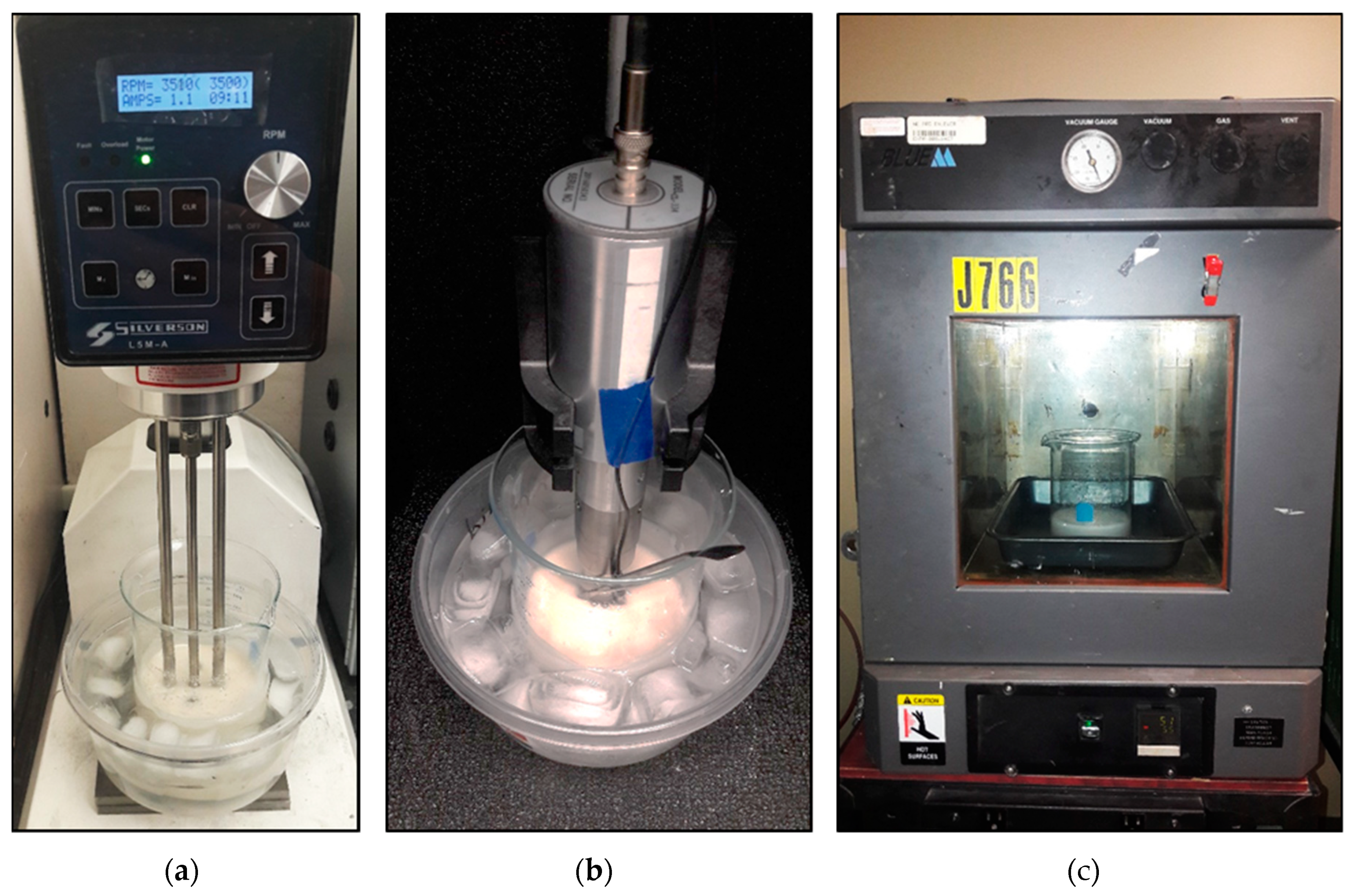
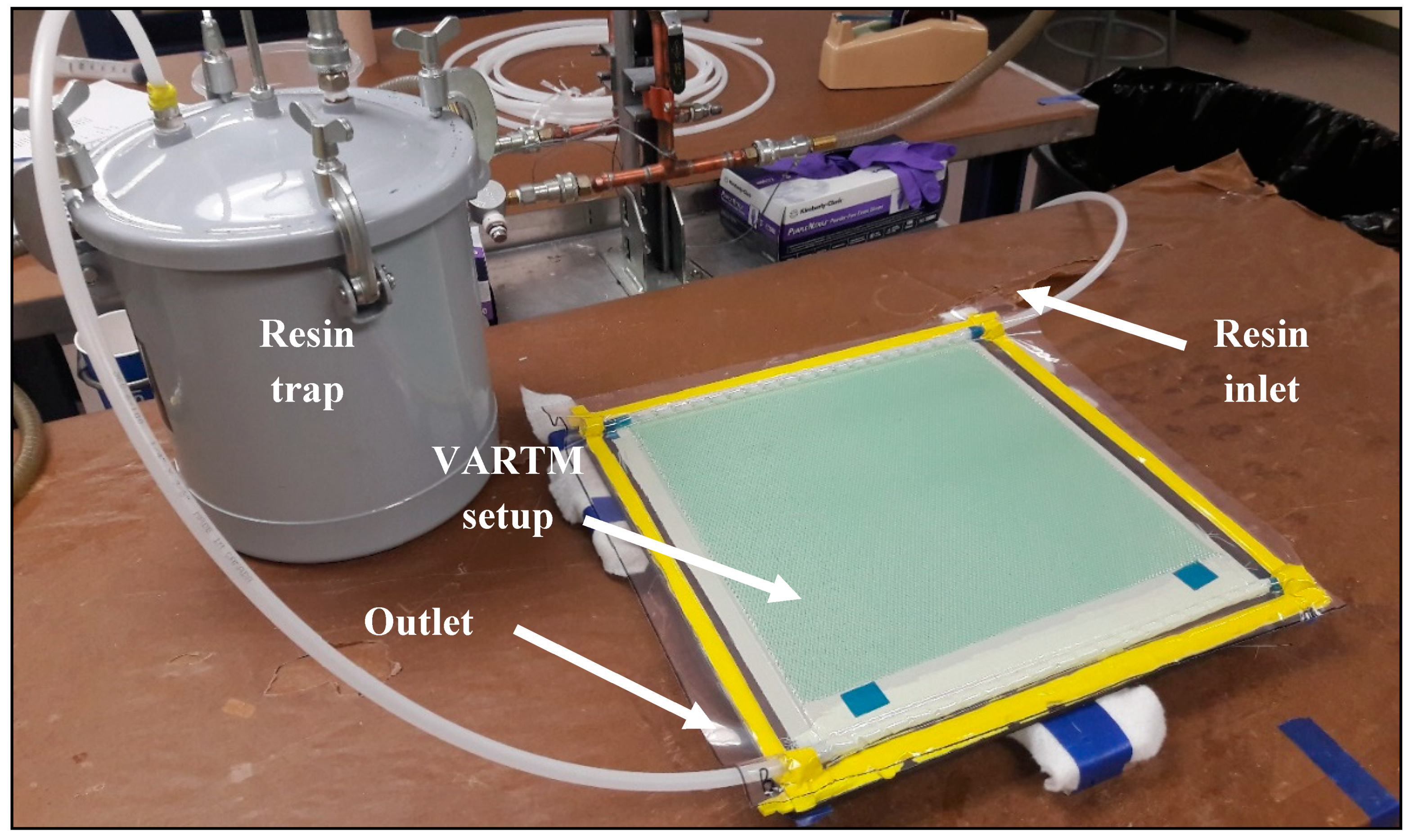
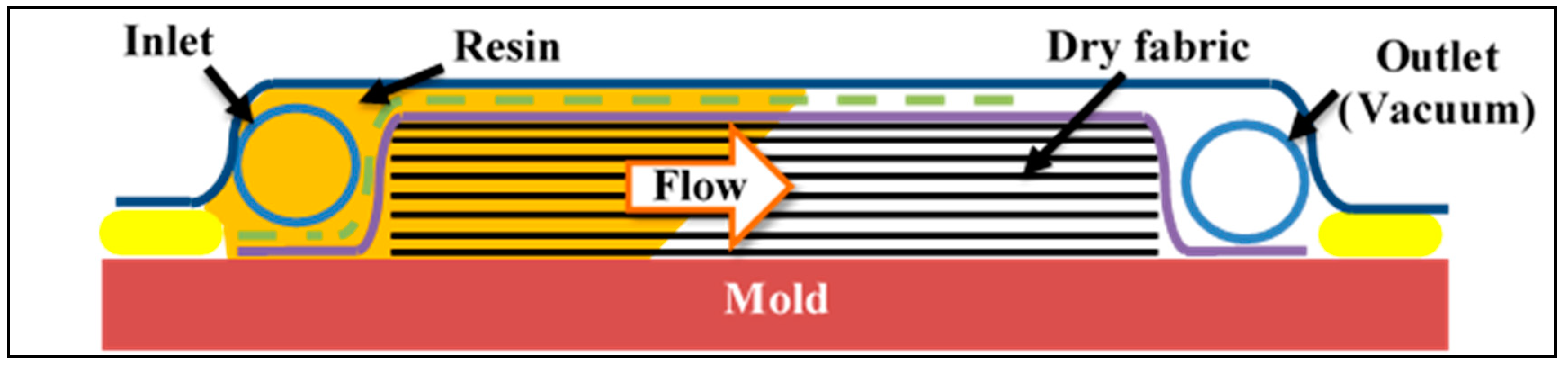
2.1. Materials Preparation

A Marine 820 epoxy resin from Axson Technologies (Madison Heights, MI, USA) was used for the laminate fabrication. A nano organophilic phyllosilicate (Garamite-1958) and a micronized polytetrafluoroethylene (PTFE) modified polyethylene wax (Ceraflour-996) were used as fillers in the epoxy resin, according to the concentrations presented in Table 1, which follows a three-level factorial design. Nanoclay content was limited to 2 wt % and wax at 1.5 wt %. A second experiment series was carried out by adding 1% of a BYK-W-972 wetting agent (WA) to observe improvement. Nevertheless, no WA was added into the 0% clay/0% wax sample. Qualix, a division of Dempsey Corporation (Saint Laurent, QC, Canada) supplied all fillers.
The resin modification process started by drying the clay for two hours in a vacuum oven at 55 °C to remove moisture. All additives were then mixed into the resin for one hour with a Silverson L5M-A (Silverson Machines, Inc., East Longmeadow, MA, USA) high shear mechanical mixer set at 3500 rpm. The solution was then sonicated for 30 min using a Qsonica Q700 sonicator (Qsonica, Newtown, CT, USA), because it is an essential stage for obtaining the clay platelets’ exfoliated structure [32]. The beaker was placed into an iced water bath to evacuate the generated heat during these steps. Finally, resin was degassed to remove air bubbles introduced by mixing and sonication. Prior to degassing, the resin was heated at 55 °C to lower its viscosity and facilitate bubble migration. These steps are illustrated in Figure 1. Once the resin was ready, hardener was added according to the ratio advised by the supplier and mixed manually.
Unidirectional laminates were prepared by vacuum-assisted resin transfer molding (VARTM) method with the modified resins prepared above (Figure 2). Ten plies of TC-09-U unidirectional high modulus carbon fiber from Texonic Inc. (Saint-Jean-sur-Richelieu, QC, Canada) were used to obtain a [+45]10 laminate with a final thickness of 3 mm. As illustrated in Figure 3, VARTM method consisted of using a vacuum to infuse the carbon fabric with the resin.

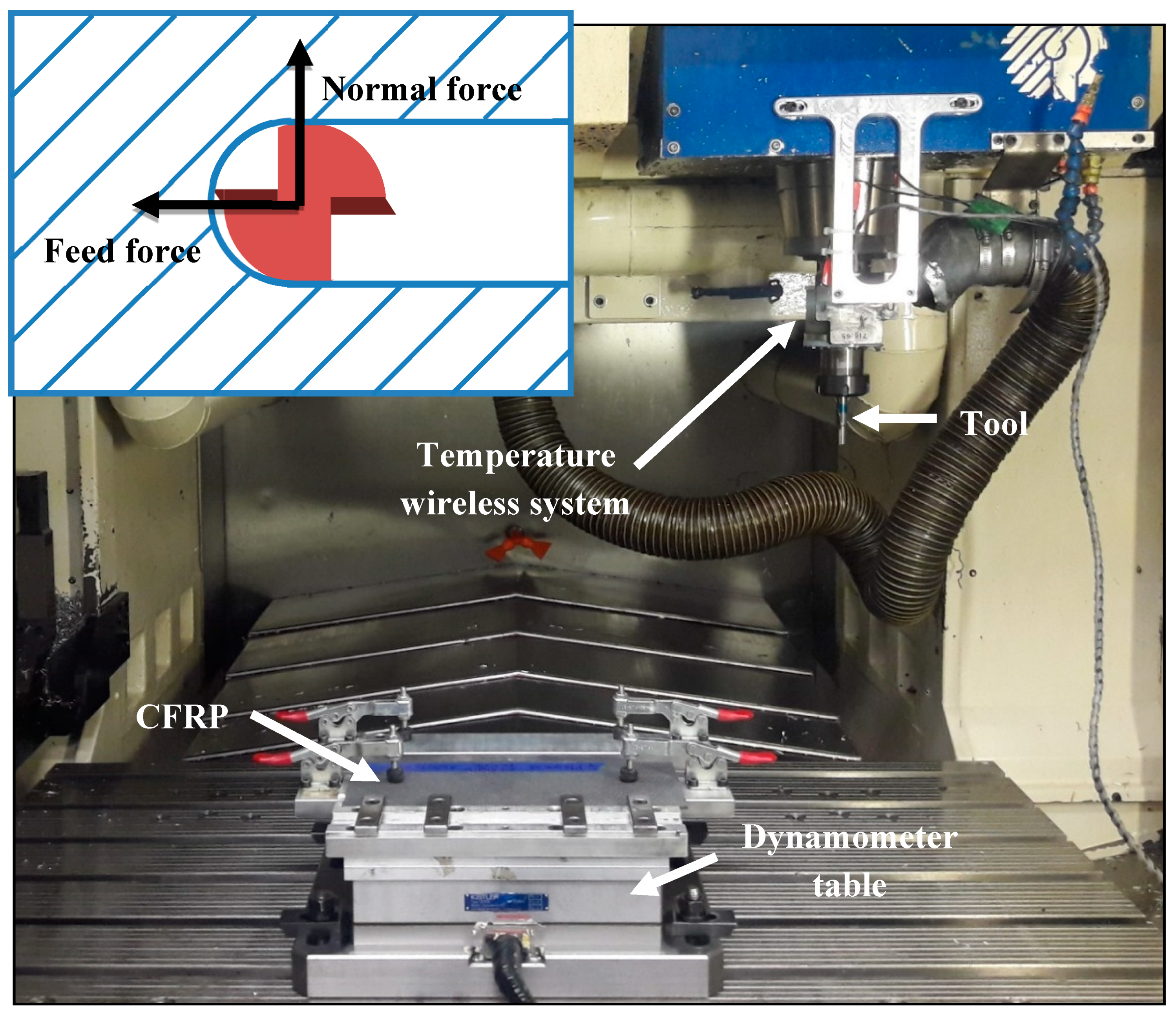
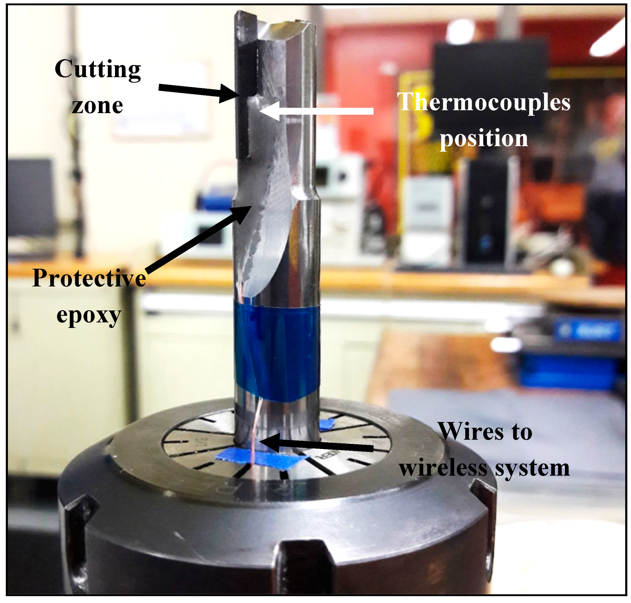
2.2. Machining Tests

All laminate’s widths were trimmed at 300 mm by a circular diamond saw prior to being machined. Fully engaged tool milling tests were performed on a Huron K2X10 three-axis CNC (computer numerical control) machine (HURON, Strasbourg, France) in dry cutting conditions (Figure 4). Fiber orientation of −45° was chosen, since it produces the worst cutting mechanism case by causing frequent damages such as fiber pull-out, uncut fibers, and matrix cracking [5,6]. The machining fixture was mounted directly on a Kistler 9255B three-axis dynamometer (Kistler, Winterthur, Switzerland) to record cutting forces at a 48 kHz sampling. According to a previous study on the current tool [33], cutting speed was fixed at 400 m/min and feed rate at 0.254 mm/rev, these parameters have been found to optimize cutting conditions.
Two identical PCD tools were employed, one for each experimental series. Geometrical specifications are given in Table 2. PCD material was chosen to prevent wear effects on cutting forces and temperatures and show best tool life. Type-K thermocouples (from Omega, Norwalk, CT, USA) were bonded on both tool teeth with thermally conductive cement (Omegabond 400 also from Omega) to ensure good linkage (Figure 5). The cement was covered with an epoxy glue to protect it from separating. The smallest wire diameter available (0.08 mm) was used, to minimize response time. Thermocouples were also in stalled at 1.7 mm from the first CFRP ply, which was determined as the minimum distance that prevents separation [11]. Temperature data were obtained by a wireless thermocouple measurement system integrated in a special mandrel (M320 from Michigan Scientific Corporation, Milford, MI, USA).

2.3. Mechanical Tests

Three-point flexural tests were carried out according to ASTM D7264. Six specimens were directly cut from each laminate. The same fiber orientation was kept (45°). The precision cutting machine used (Struers Secotom 50, Struers, Mississauga, ON, Canada) was equipped with a circular diamond saw which allowed it to directly reach the geometrical tolerances demanded by the standard. A universal testing machine (MTS Alliance RF/200, MTS Systems Corporation, Eden prairie, MN, USA) was used and the crosshead speed was set at 1 mm/min until specimen breakage. Maximum flexural stress (σF) and flexural chord modulus of elasticity (EF) were determined using Equations (1) and (2). As suggested by the standard, the strain range between 0.001 and 0.003 was chosen to calculate EF.
σ F = 3 · F m a x · L 2 · b · h ²
and
E F = Δ σ Δ ε
with, Fmax—maximum force (N); L—support span (mm); b—width (mm); h—thickness (mm); ε—strain (mm/mm).
Interlaminar shear strength (ILSS) test is very specific to composite materials and is performed as an indicator of the fiber–matrix interaction [34]. It consists of bending a short-beam specimen so shear stress is induced into the plane of the specimen, which tends to make the plies slip on themselves. Therefore, six short-beam specimens were produced from each laminate by the same method as the flexural ones. A fiber orientation of 0° along the specimen span was taken to respect the standard requirements. Tests were carried out at a crosshead speed of 1 mm/min according to ASTM D2344 and using the same testing machine as previously. ILSS were calculated from the measured forces.
ILSS = 0.75 · F m a x A
with, Fmax—maximum force (N); A—Section (mm²).
Tensile tests were only performed on the experimental series with 1% WA, because of time and economic issues related to this university–industry partnership. As a high correlation with flexural tests occur, tensile tests on both experimental series were found not to be necessary. Specimens’ preparation and test procedure followed all the directives given by ASTM D3039. Comparatively to metals, tensile tests on composite materials are quite difficult and cause some issues. Tensile specimens need to be rectangular shaped because of their high anisotropy. However, this shape makes failures occur close to the grips instead of the gage region [35,36,37]. Thus, 50 mm tabs made from [±45]3S GFRP were bonded on each side of the specimens, as recommended by the standard, to avoid grip failure occurrence. Seven 25 × 250 mm specimens were cut from each laminate, using a circular diamond saw, with a fiber orientation of 45°. Tensile tests were carried out on an MTS Landmark hydraulic testing machine at a head speed of 1 mm/min. The chord modulus of elasticity was determined over the strain range of 0.001 to 0.003, in accordance with the standard. An extensometer was used to allow an accurate strain measurement. Tensile strength (σT) and chord modulus of elasticity (ET) were calculated from the data.
σ T = F m a x A
and
E T = Δ σ Δ ε    
with, Fmax—maximum force (N); A—Section (mm²); ε—strain (mm/mm).

2.4. Constituent Content Tests

The fiber volume fractions were determined to explain the changes in mechanical properties. Three 25 × 40 mm rectangular specimens were cut from each laminate. As it is required for calculation, accurate density of each sample was determined by the displacement method specified in ASTM D792. Specimens were firstly weighed in air then in demineralized water. Water temperature was measured in order to determine its density using charts given by the standard. All weight measurements were performed to the nearest 0.1 mg, as demanded by the standard. Finally, composite density was calculated according to the following equation:
ρ C = M M M w a t e r · ρ w a t e r
with M—mass (g); Mwater—apparent mass in water (g); ρwater—water density (g/cm3).
Composite content tests were performed according to procedure G of ASTM D3171, which consists of matrix burn off by pyrolysis. Specimens were then burned at 540 °C for five hours in air, using a crucible. The chosen duration and temperature allowed removing all matrices without altering the fibers. The specimens were weighed before and after pyrolysis. The fiber volume content was then determined.
V f = M f M i · ρ c ρ f
with Mf—final mass (g); Mi—initial mass (g); ρf—fiber density (g/cm3).

3. Results and Discussion

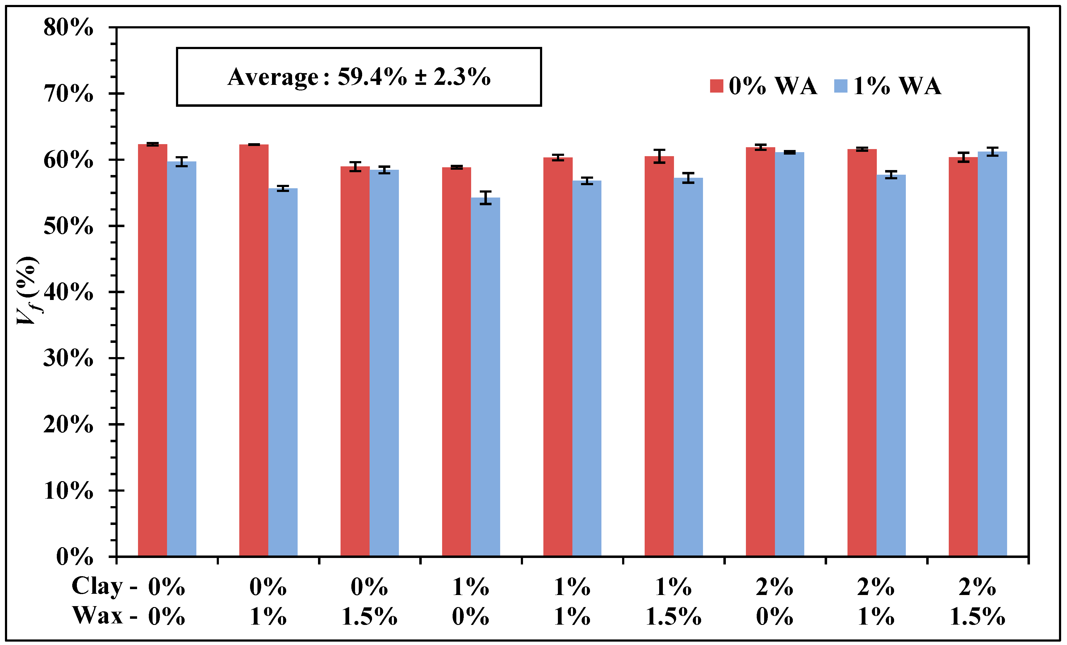
3.1. Fiber Volume Fraction

Thanks to the VARTM process, fiber volume fractions were relatively high, with a mean value of 59.4%. Nevertheless, slight variations were observed in the fiber volume fraction, as shown in Figure 6, which were attributed to the variability of the VARTM process. This variability was also amplified by resin viscosity increase due to fillers. Indeed, changes in resin viscosity were qualitatively observed, while resins were decisive in the VARTM processes since too high of a viscosity may have caused higher fiber volume fractions or even failed to properly impregnate the fiber fabrics [38,39]. Other studies have noticed that the addition of fillers such as organoclay into the resin led to an increased viscosity, which caused variations in the fiber volume fraction of the laminate [25,40].

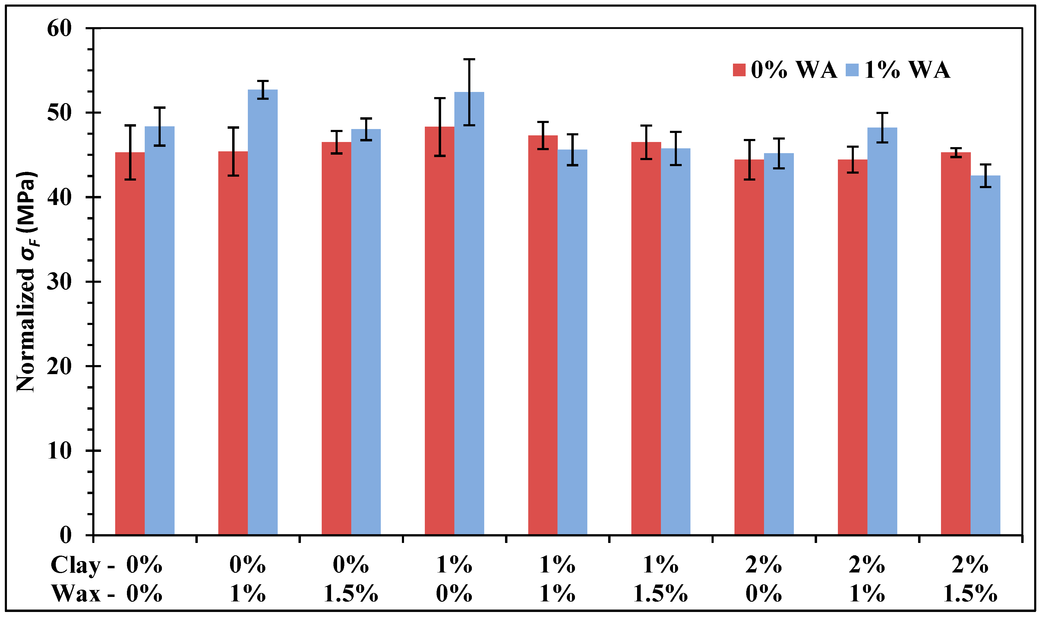
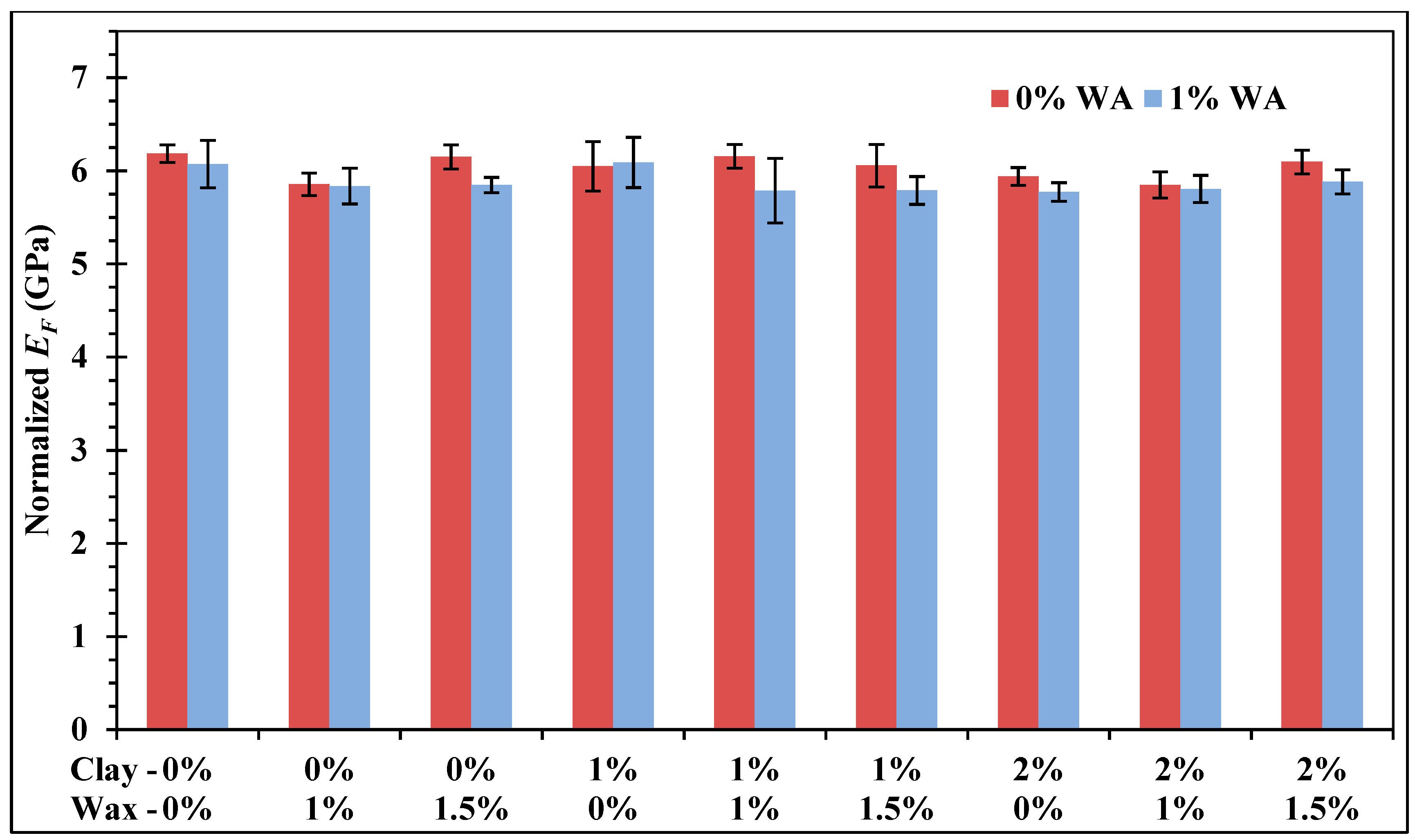
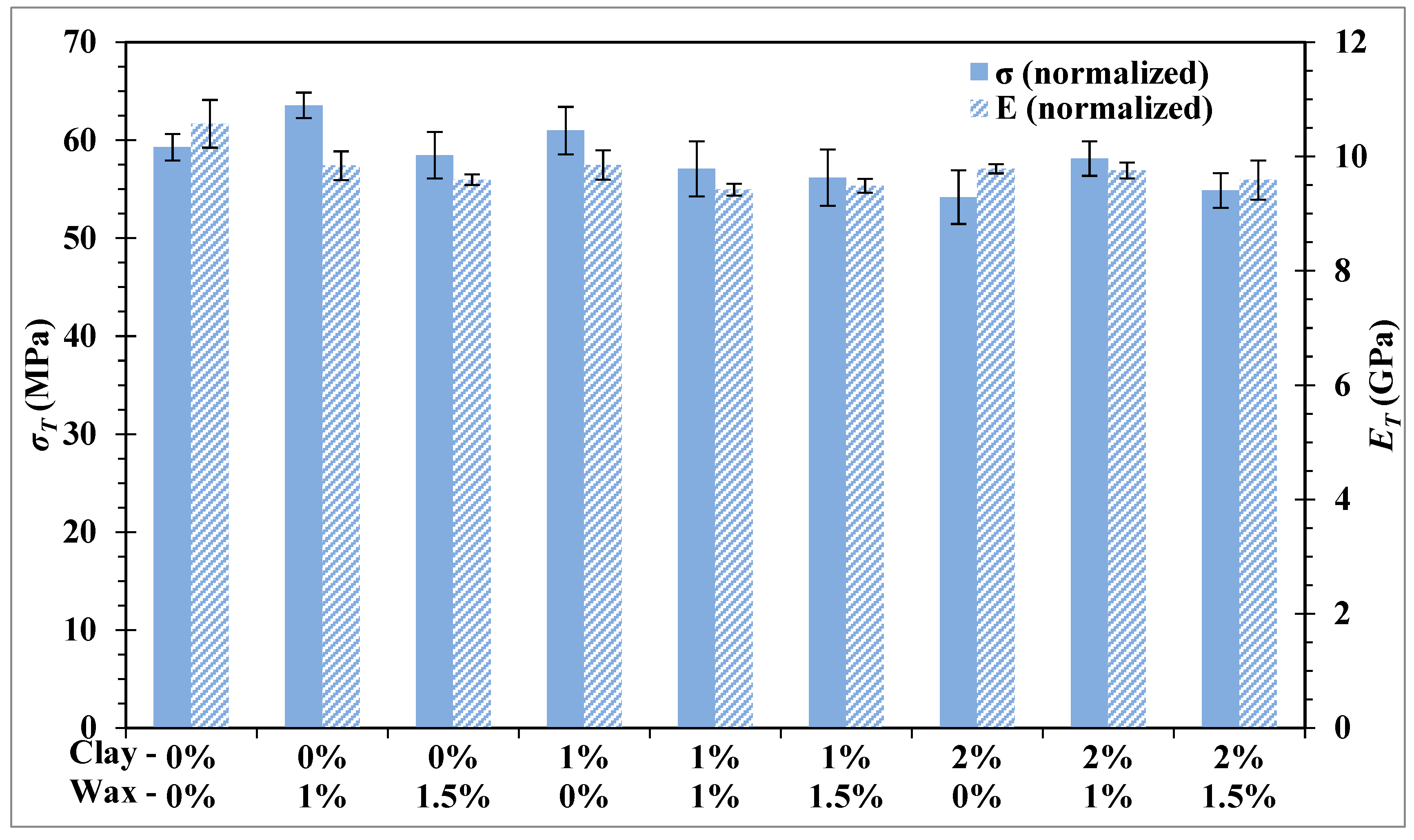
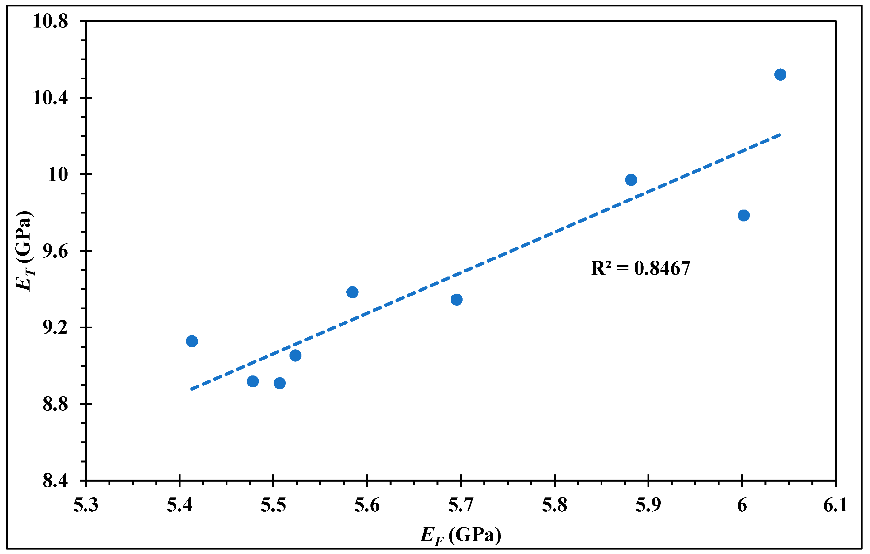
3.2. Mechanical Properties

In order to examine the effects of fillers on mechanical properties, flexural, short-beam, and tensile tests were performed on samples. However, since fiber volume fraction linearly affects some mechanical properties in composite materials, strength and stiffness were normalized to a Vf of 60% using the Equation (8) [36].
Normalized   value = Test   Value · 0.6 V f
Normalized values bypass the fiber volume fraction effect and allow comparison between samples. In addition, in order to properly discern significant changes in the large number of samples, an analysis of variance (ANOVA) was performed. For all mechanical tests, the ANOVAs led to acceptance of the hypothesis that average values differ between samples, with a p-value lower than 0.05%.
Flexural tests were performed on both experimental series, with and without wetting agent. Normalized flexural strength and stiffness are shown in Figure 7 and Figure 8, respectively. For both flexural strength and stiffness, no trend between mechanical properties and filler concentrations was distinguishable, no mathematical modeling was found either. Indeed, all samples showed relatively close values, and only a few samples were found to be significantly different from others by the ANOVA. Comparatively to the neat epoxy, a significant improvement in strength was observed for the sample with 1% wax and 1% WA. This result was not expected since wax is not known to improve mechanical properties, but is ordinarily only used for lubrication needs [27,28]. However, this sample did not lead to the same improvement on stiffness, whereas the neat epoxy remained statistically equal or stiffer than others. Variations between both experimental series were seen on strength, which means that WA may have interactions with clay and wax, in contrast to stiffness, where WA has no influence. Mechanical properties are generally improved in polymers by the addition of particles which help to block the deformation under load [28]. Such a behavior was expected from clay, which was expected to increase mechanical properties more significantly, as observed by others [19,20,21]. This was not due to interaction with other fillers, because even samples with only clay/epoxy were not changed. It might be due to the kind of phyllosilicate present in the current additive. More experiments should be carried out with other organoclay additives to confirm this hypothesis. However, despite the three filler addition, almost none of the samples showed significant decrease of the flexural properties.
Short-beam tests were performed in order to investigate the effects of fillers on the fiber–matrix interaction. ILSS are presented in Figure 9 with and without WA, data are not normalized here since short-beam strength is not a fiber fraction dominated value [36]. Contrary to flexural tests, clay has been shown to have a tendency to increase ILSS. Comparatively to the neat epoxy, an addition of 1% clay led to a significant ILSS improvement of 5%. Similarly, 2% clay gave the best results despite the large uncertainties. Organoclays are well known to provide a better bonding between fiber and matrix and the present observation joins the conclusions made by other studies [19,26]. However, as presumed before, WA have an interaction with clay, since the same concentrations were not statistically different to the reference in the second experimental series. As observed for flexural tests, the sample with 1% wax and 1% WA is also statistically significant on ILSS.
Tensile tests are generally useful to determine the intrinsic mechanical properties of a material [35]. Tensile tests were performed on the 1% WA experimental series. Figure 10 shows normalized stresses and chord modules of elasticity. These tests revealed conclusions close to the flexural ones. Both showed similar trends and the ANOVAs revealed the same significant samples as previously, such as the sample with 1% wax and 1% WA, which also improved tensile strength. The similarity between both tests can be seen in Figure 11, where a positive correlation between the flexural and tensile chord modulus of elasticity appears. This observation is explained by the traction-compression, which occurs into flexural specimens while bending. Other authors have demonstrated the possibility to estimate tensile properties through the flexural test, which is easier to perform [41,42]. Due to this high correlation, as well as time and economic issues related to this university–industry partnership study, the implementation of the tensile tests were not performed on the 0% WA experimental series. As proposed by the industrial partner, this study aims to investigate the effect of fillers on CFRP. Thus, flexural tests alone are enough to have a preview of fillers’ effect on mechanical properties in the present study. Deeper measurements of tensile properties will be done in further studies.

3.3. Machinability

Given that PCD provides the best tool life [3] and that the total cutting length is relatively low for our tests, effect of tool wear on forces and temperatures was assumed negligible. Inspection of the tools’ wear confirmed this hypothesis, almost no wear was apparent after all machining tests.
Cutting forces are generally considered to be one of the main machinability indicators [43]. Reduced forces are great since they allow for softening of the cutting mechanism and slowing down the tool wear. Forces were measured during cutting using the dynamometer table, and both feed and normal direction forces are presented in Figure 12. The normal and feed forces showed similar tendencies, a correlation coefficient of 95.7% was calculated between both forces. Normal forces were, nevertheless, lower than feed forces. Depending on the concentration of fillers, differences were observed between the samples. Almost all concentrations allowed us to obtain forces lower than the neat epoxy reference. Wetting agent decreased the forces. Samples from the experimental series with 1% WA were lower comparatively to the second experimental series. All samples with 1% wax showed reduced forces, regardless of the nanoclay content. However, at a concentration of 1.5% forces increased back. Hence, a wax concentration of 1% seems to be an optimized percentage. Organoclay also has the capability to improve machinability. It was observed that the more the concentration is increased, the more the forces are reduced. The best improvement was seen for a concentration of 2% of organoclay, 1% wax, and 1% WA in the matrix according to the present results. Comparatively to the neat epoxy sample, this concentration allows us to decrease the feed force by 37% and the normal force by 15%.
Cutting temperatures are an important point in CFRP machining because of the sensibility of polymers to heat. Typical temperature curves measured through the thermocouples are shown in Figure 13. Once the tool starts to cut, temperatures rapidly increase and then show a tendency to converge towards a final value. The cutting length is not long enough to reach the final temperatures, but differences between samples are nonetheless seen at the end of the test. As expected, even with a new PCD tool, cutting temperature exceeds 170 °C after only 300 mm of machining, while most epoxy matrices have a glass transition temperature of about 160 °C [1,28]. Damages may then happen on the surface while cutting, confirming the relevance of thermal aspect problems during CFRP machining.
Given that all CFRP laminates were trimmed precisely at the same width, the final temperatures measured (at a cutting length of 300 mm) were thereafter used to compare samples. An influence of fillers on temperatures was visible (Figure 14). Both experimental series had the same tendencies but were shifted by about a few degrees. No interactions of wetting agent on temperatures can be asserted, the lag between the series with and without wetting agent can be explained by a tool change. Two identical tools are used for this study, one for each experimental series. Due to their tiny size, thermocouples are difficult to place precisely on the tools. Thermal responses are, hence, slightly different between both tools. However, variations in each experimental series are confident since the tool used did not change. Independently of WA, lower temperatures were nevertheless observed for all the combinations that had a concentration of 1% wax or 2% clay. As noticed for forces, the best improvements on temperatures were obtained by the samples with 1% wax and 2% clay. Drops of 11 °C and 18 °C, respectively, were observed for the 0% WA and 1% WA series with this combination.
Temperatures seem to follow the same trends as normal forces. To investigate this relation, temperature as a function of normal force is traced in Figure 15. Temperatures are clearly separated into two groups, depending on the experimental series. As explained previously, both tools used are identical but the groups formed are due to the difference in thermocouple response. The more suitable hypothesis is that even if thermocouples were bonded with care, they probably were situated a bit closer to the surface of the tool. Thus, tool B used for the 1% WA series presumably had a better thermal bonding with the thermocouples than tool A. This hypothesis explains why higher temperatures are obtained with WA. A strong correlation exists between temperatures and forces. Temperatures increase linearly with normal forces. This result allows confirmation of the hypothesis that heat is mainly produced by friction, which is commonly assumed in CFRP machining [7,8]. This also helps to understand how temperatures are decreased. Fillers actually have no direct effect on temperatures, but they do on forces. By decreasing the forces, lower temperatures are obtained.

4. Conclusions

In this study, CFRP plaques were made using an epoxy resin filled with nano organoclay, wax, and a wetting agent. Machining tests were carried out using thermocouples fixed to PCD tools in order to investigate the machinability of the fabricated CFRP, while mechanical tests were carried out to inspect changes in mechanical properties. According to the presented results, the following conclusions are made:
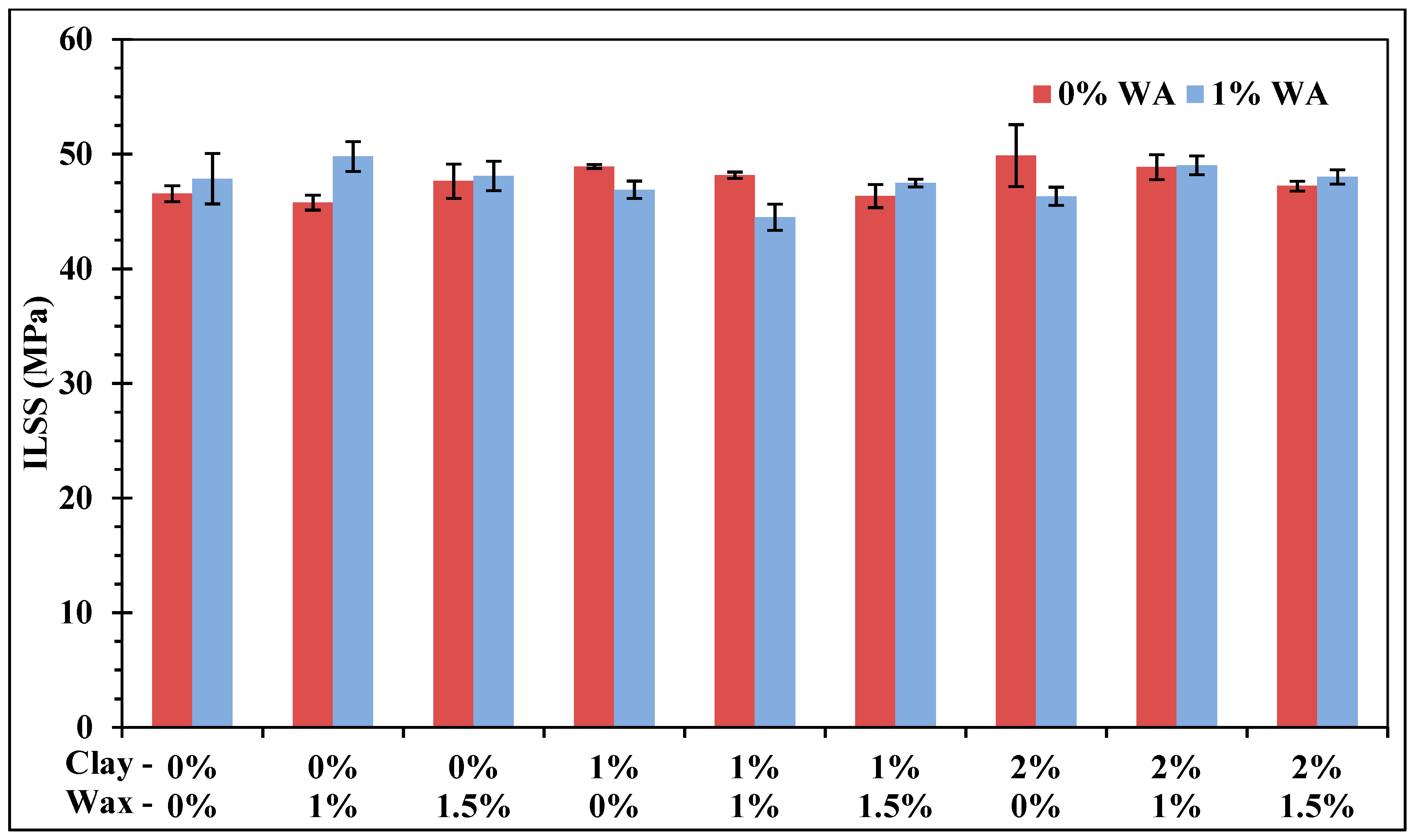
  • Without wetting agent, a concentration of 2 wt % of organoclay improved the fiber-matrix interface of the CFRP. At this concentration, ILSS had been increased about 7%.
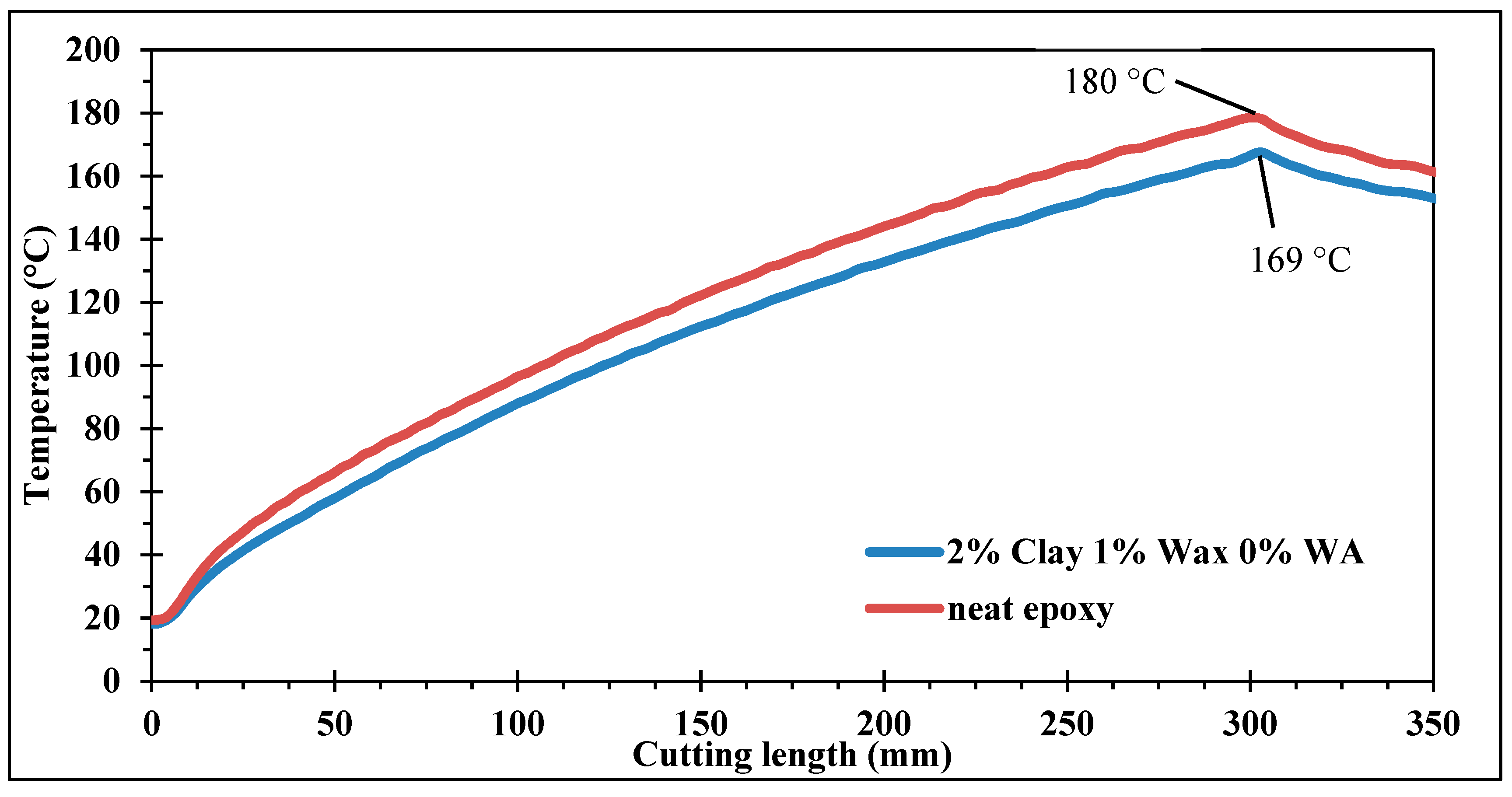
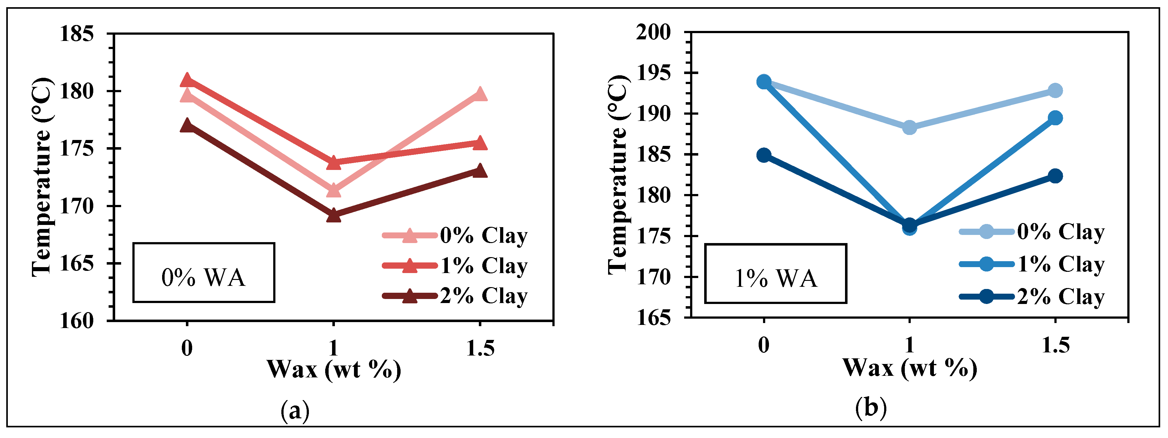
  • Tool temperatures quickly exceed matrix glass transition temperature, even with a new sharp tool. Attention to the thermal aspect should be taken during composite machining.
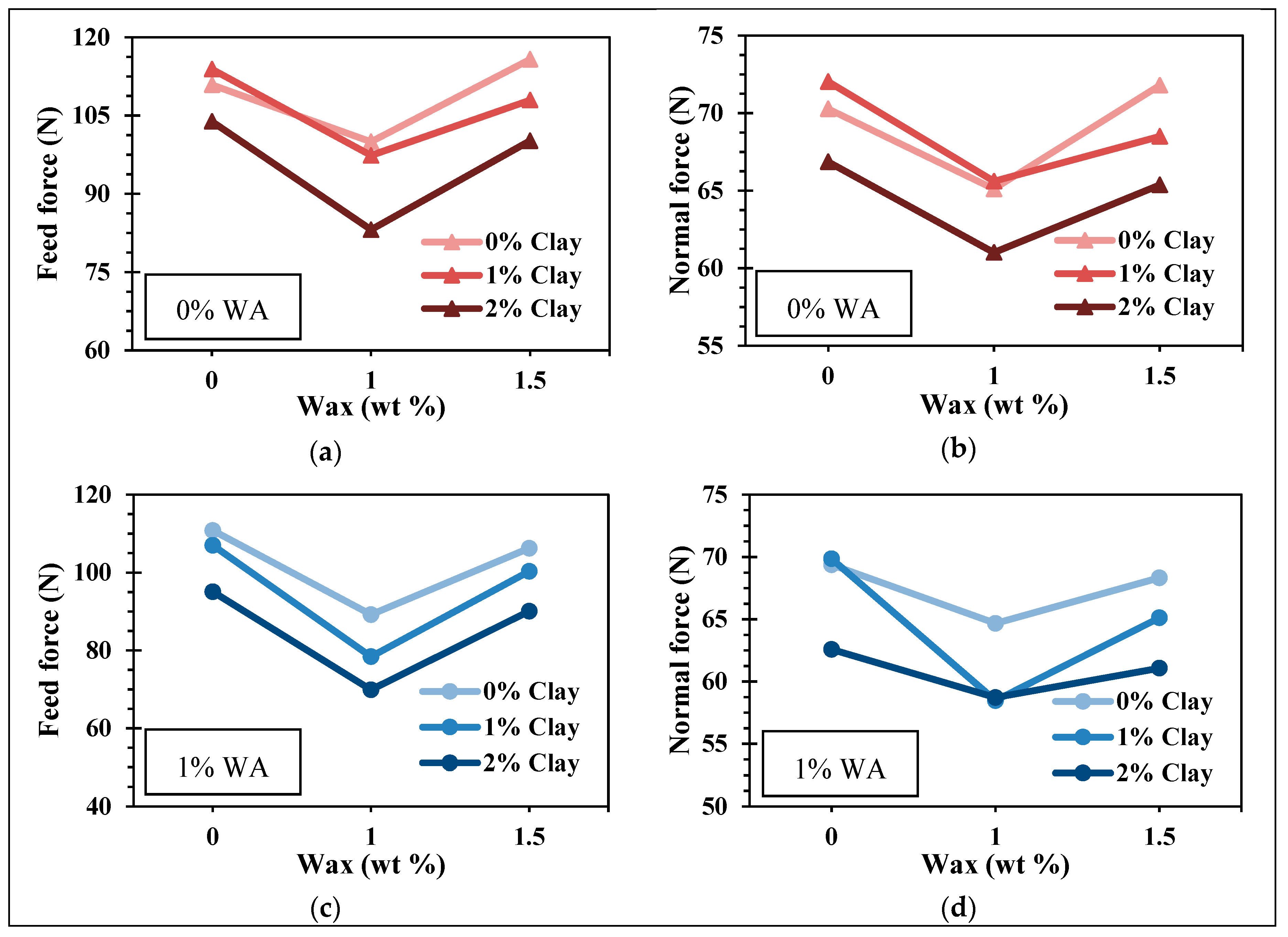
  • Independently of clay concentration, 1 wt % of wax in the epoxy matrix decreased cutting forces and temperatures. Organoclay effect was less important than wax, but also allowed increasing machinability at a concentration of 2 wt %. The best improvement was observed with 2% organoclay, 1% wax, and 1% WA, which allows us to decrease feed forces by 37%, normal forces by 15%, and temperatures by 18 °C.
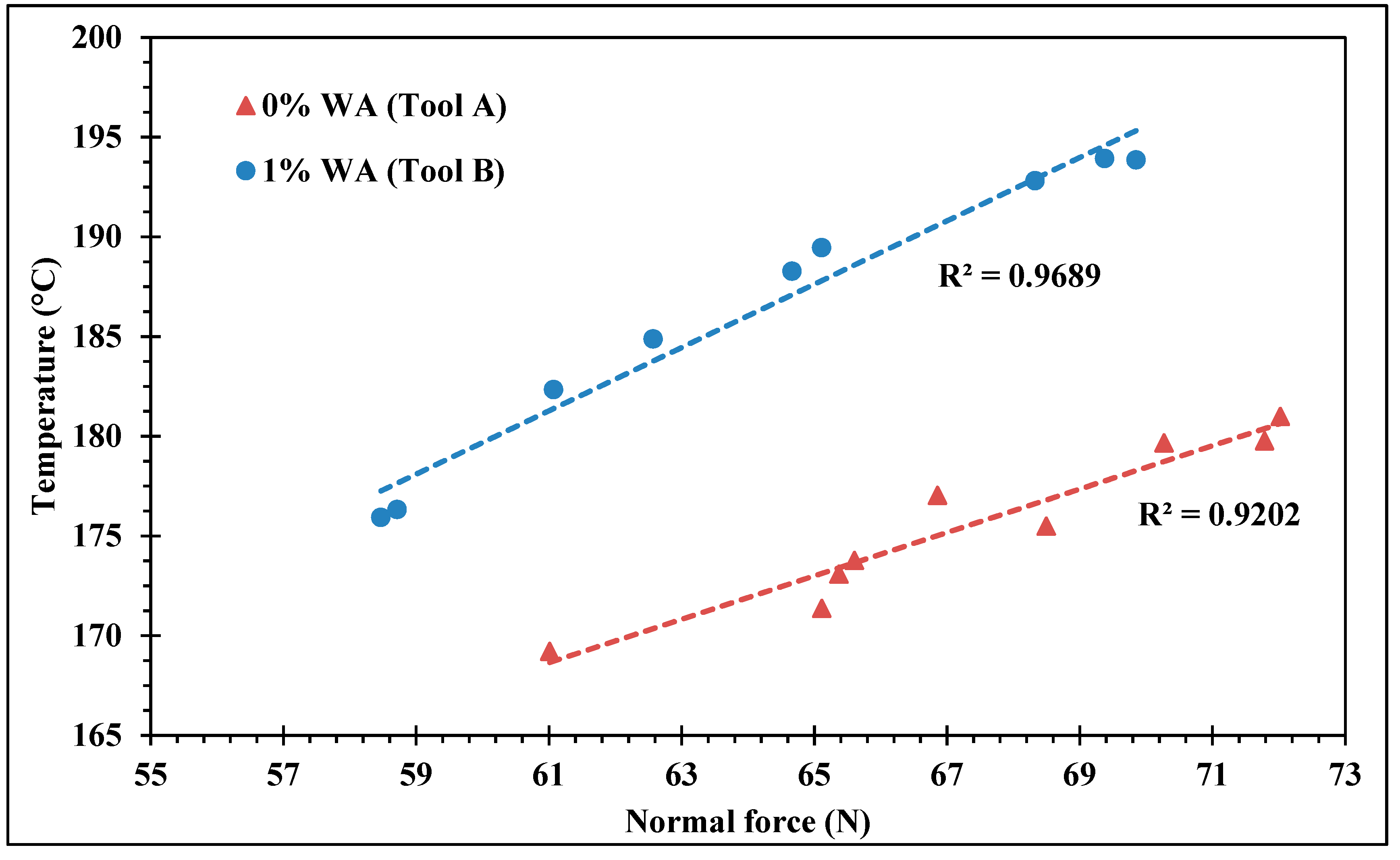
  • A strong correlation exists between normal forces and temperatures. This correlation proves that heat is generated largely by friction at the tool/workpiece interface in CFRP machining. The temperature decreases are, hence, fallout of the reduced forces allowed by the additives.
  • The laminates filled with additives had a better machinability without altering their mechanical properties.

Author Contributions

J.F.C. and C.O.P. designed and directed the study. K.E.G. and R.M. performed all the experiments, measurements, and analysis of the results. The writing and revision of the manuscript were performed according to the order of the authors.

Funding

This work was funded by the Natural Sciences and Engineering Research Council of Canada (NSERC). The wax and Nanoclay particles as well as the wetting agent were supplied as in-kind materials by Qualix, a division of Dempsey Corporation.

Acknowledgments

We sincerely thank Claude-Daniel Legault, Nabil Mazeghrane, and Éric Marcoux who provided technical assistance during this research.

Conflicts of Interest

The authors declare no conflict of interest.

References

  1. Bathias, C.; Wolff, C. Matériaux Composites; Dunod: Paris, France, 2005; p. 417. [Google Scholar]
  2. Bouvet, C. Mechanics of Aeronautical Composite Materials; Wiley: Hoboken, NJ, USA, 2017. [Google Scholar]
  3. Davim, J.P. Machining Composite Materials; John Wiley & Sons: London, UK, 2010; p. 262. [Google Scholar]
  4. Wang, D.; Ramulu, M.; Arola, D. Orthogonal cutting mechanisms of graphite/epoxy composite. Part I: Unidirectional laminate. Int. J. Mach. Tools Manuf. 1995, 35, 1623–1638. [Google Scholar] [CrossRef]
  5. Wang, X.; Zhang, L. An experimental investigation into the orthogonal cutting of unidirectional fibre reinforced plastics. Int. J. Mach. Tools Manuf. 2003, 43, 1015–1022. [Google Scholar] [CrossRef]
  6. Wang, C.; Ming, W.; An, Q.; Chen, M. Machinability characteristics evolution of CFRP in a continuum of fiber orientation angles. Mater. Manuf. Processes 2017, 32, 1041–1050. [Google Scholar] [CrossRef]
  7. Ghafarizadeh, S.; Lebrun, G.; Chatelain, J.F. Experimental investigation of the cutting temperature and surface quality during milling of unidirectional carbon fiber reinforced plastic. J. Compos. Mater. 2016, 50, 1059–1071. [Google Scholar] [CrossRef]
  8. Xu, J.; Li, C.; Dang, J.; El Mansori, M.; Ren, F. A study on drilling high-strength cfrp laminates: Frictional heat and cutting temperature. Materials 2018, 11, 2366. [Google Scholar] [CrossRef] [PubMed]
  9. Yashiro, T.; Ogawa, T.; Sasahara, H. Temperature measurement of cutting tool and machined surface layer in milling of CFRP. Int. J. Mach. Tools Manuf. 2013, 70, 63–69. [Google Scholar] [CrossRef]
  10. Delahaigue, J.; Chatelain, J.F.; Lebrun, G. Influence of cutting temperature on the tensile strength of a carbon fiber-reinforced polymer. Fibers 2017, 5, 46. [Google Scholar] [CrossRef]
  11. Mullier, G.; Chatelain, J.F. Influence of thermal damage on the mechanical strength of trimmed CFRP. Int. J. Mech. Mechatron. Eng. 2015, 9, 1559–1566. [Google Scholar]
  12. Mkaddem, A.; Ben Soussia, A.; El Mansori, M. Wear resistance of CVD and PVD multilayer coatings when dry cutting fiber reinforced polymers (FRP). Wear 2013, 302, 946–954. [Google Scholar] [CrossRef]
  13. Azmi, A.I.; Lin, R.J.T.; Bhattacharyya, D. Machinability study of glass fibre-reinforced polymer composites during end milling. Int. J. Adv. Manuf. Technol. 2013, 64, 247–261. [Google Scholar] [CrossRef]
  14. Hamedanianpour, H.; Chatelain, J.F. Effect of tool wear on quality of carbon fiber reinforced polymer laminate during edge trimming. Appl. Mech. Mater. 2013, 327, 34–39. [Google Scholar] [CrossRef]
  15. Slamani, M.; Chatelain, J.F.; Hamedanianpour, H. Influence of machining parameters on surface quality during high speed edge trimming of carbon fiber reinforced polymers. Int. J. Mater. Form. 2018, 12, 331–353. [Google Scholar] [CrossRef]
  16. Azeez, A.A.; Rhee, K.Y.; Park, S.J.; Hui, D. Epoxy clay nanocomposites–processing, properties and applications: A review. Compos. Part B 2013, 45, 308–320. [Google Scholar] [CrossRef]
  17. Gloaguen, J.M.; Lefebvre, J.M. Nanocomposites polymères/silicates en feuillets. 2007. L'expertise Technique et Scientifique de Référence. Available online: https://www.techniques-ingenieur.fr/base-documentaire/materiaux-th11/materiaux-a-proprietes-mecaniques-42535210/nanocomposites-polymeres-silicates-en-feuillets-n2615/ (accessed on 20 August 2019).
  18. Aradhana, R.; Mohanty, S.; Nayak, S.K. High performance epoxy nanocomposite adhesive: Effect of nanofillers on adhesive strength, curing and degradation kinetics. Int. J. Adhes. Adhes. 2018, 84, 238–249. [Google Scholar] [CrossRef]
  19. Chowdhury, F.; Hosur, M.; Jeelani, S.; Chowdhury, F. Studies on the flexural and thermomechanical properties of woven carbon/nanoclay-epoxy laminates. Mater. Sci. Eng. A 2006, 421, 298–306. [Google Scholar] [CrossRef]
  20. Tcherbi-Narteh, A.; Hosur, M.; Zainuddin, S.; Jeelani, S. Compression and flexural response of carbon/epoxy-nanoclay nanocomposites subjected to UV radiation and condensation. In Proceedings of the 2010 International Mechanical Engineering Congress and Exposition, Vancouver, BC, Canada, 12–18 November 2010. [Google Scholar]
  21. Zhou, Y.; Pervin, F.; Rangari, V.K.; Jeelani, S. Influence of montmorillonite clay on the thermal and mechanical properties of conventional carbon fiber reinforced composites. J. Mater. Process. Technol. 2007, 191, 347–351. [Google Scholar] [CrossRef]
  22. Aboubakr, S.H.; Salas, C.; Reda Taha, M.M. Low velocity impact strength of CFRP composites incorporating nanoclay. In Proceedings of the 30th Annual Technical Conference of the American Society for Composites 2015, East Lansing, MI, USA, 28–30 September 2015. [Google Scholar]
  23. Sakthivel, T.; Prabu, S.B. Influence of addition of nanoclay on the mechanical behavior of polymer nanocomposite. Trans. Indian Inst. Met. 2008, 61, 73–76. [Google Scholar] [CrossRef]
  24. Dorigato, A.; Pegoretti, A.; Quaresimin, M. Thermo-mechanical characterization of epoxy/clay nanocomposites as matrices for carbon/nanoclay/epoxy laminates. Mater. Sci. Eng. A 2011, 528, 6324–6333. [Google Scholar] [CrossRef]
  25. Khan, S.U.; Munir, A.; Hussain, R.; Kim, J.-K. Fatigue damage behaviors of carbon fiber-reinforced epoxy composites containing nanoclay. Compos. Sci. Technol. 2010, 70, 2077–2085. [Google Scholar] [CrossRef]
  26. Quaresimin, M.; Salviato, M.; Zappalorto, M. Fracture and interlaminar properties of clay-modified epoxies and their glass reinforced laminates. Eng. Fract. Mech. 2012, 81, 80–93. [Google Scholar] [CrossRef]
  27. Lutz, J.T. Thermoplastic Polymer Additives: Theory and Practice, 1st ed.; Marcel Dekker: New York, NY, USA, 1989; p. 523. [Google Scholar]
  28. Seymour, R.B. Reinforced Plastics: Properties and Applications; ASM International: Materials Pars, OH, USA, 1991; p. 257. [Google Scholar]
  29. Otaigbe, J.U.; McAvoy, J.M. Gas atomization of polymers. I. Feasibility studies and process development. Adv. Polym. Technol. 1998, 17, 145–160. [Google Scholar] [CrossRef]
  30. Peinado, M. Le Plastique Arme: Application au Materiel Tubulaire; Technip: Paris, France, 1986; p. 266. [Google Scholar]
  31. Lasri, L.; Nouari, M.; El Mansori, M. Modelling of chip separation in machining unidirectional FRP composites by stiffness degradation concept. Compos. Sci. Technol. 2009, 69, 684–692. [Google Scholar] [CrossRef]
  32. Yasmin, A.; Luo, J.J.; Daniel, I.M. Processing of expanded graphite reinforced polymer nanocomposites. Compos. Sci. Technol. 2006, 66, 1182–1189. [Google Scholar] [CrossRef]
  33. Bérubé, S. Usinage en détourage de laminés composites carbone/époxy. Master’s Thesis, École de Technologie supérieure, Montreal, QC, Canada, July 2012. [Google Scholar]
  34. Narkis, M.; Chen, E.J.H.; Pipes, R.B. Review of methods for characterization of interfacial fiber-matrix interactions. Polym. Compos. 1988, 9, 245–251. [Google Scholar] [CrossRef]
  35. Hodgkinson, J.M. Mechanical Testing of Advanced Fibre Composites; Elsevier: Amsterdam, The Netherlands, 2000; p. 362. [Google Scholar]
  36. Materials Sciences Corporation; U. S. Army Research Laboratory; American Society for Testing Materials. The Composite Materials Handbook-Mil 17; Technomic: Lancaster, UK, 1997. [Google Scholar]
  37. Tahir, M.M.; Wang, W.-X.; Matsubara, T. A novel tab for tensile testing of unidirectional thermoplastic composites. J. Thermoplast. Compos. Mater. 2017, 32, 37–51. [Google Scholar] [CrossRef]
  38. Kedari, V.R.; Farah, B.I.; Hsiao, K.-T. Effects of vacuum pressure, inlet pressure, and mold temperature on the void content, volume fraction of polyester/e-glass fiber composites manufactured with VARTM process. J. Compos. Mater. 2011, 45, 2727–2742. [Google Scholar] [CrossRef]
  39. Rydarowski, H.; Koziol, M. Repeatability of glass fiber reinforced polymer laminate panels manufactured by hand lay-up and vacuum-assisted resin infusion. J. Compos. Mater. 2015, 49, 573–586. [Google Scholar] [CrossRef]
  40. Kanny, K.; Mohan, T. Resin infusion analysis of nanoclay filled glass fiber laminates. Compos. Part B Eng. 2014, 58, 328–334. [Google Scholar] [CrossRef]
  41. Almerich-Chulia, A.; Fenollosa, E.; Cabrera, I.; Almerich, A. GFRP Bar: Determining tensile strength with bending test. Adv. Mater. Res. 2015, 1083, 90–96. [Google Scholar] [CrossRef]
  42. Arczewska, P.; Polak, M.A.; Penlidis, A. Relation between tensile strength and modulus of rupture for GFRP reinforcing bars. J. Mater. Civ. Eng. 2019, 31, 04018362. [Google Scholar] [CrossRef]
  43. Trent, E.M.; Wright, P.K. Metal cutting, 4th ed.; Butterworth-Heinemann: Boston, MA, USA, 2000; p. 446. [Google Scholar]
Figure 1. Three main steps of resin modification process: (a) Mixing, (b) sonicating, and (c) degassing.
Jcs 03 00085 g001
Figure 2. Fabrication of carbon fiber reinforced plastics (CFRP) by vacuum-assisted resin transfer molding (VARTM).
Jcs 03 00085 g002
Figure 3. Schema of vacuum assisted resin transfer molding (VARTM) process.
Jcs 03 00085 g003
Figure 4. Machining setup.
Jcs 03 00085 g004
Figure 5. Thermocouples equipped polycrystalline diamond (PCD) tool.
Jcs 03 00085 g005
Figure 6. Fiber volume fraction.
Jcs 03 00085 g006
Figure 7. Normalized maximum flexural stress changes with fillers without and with wetting agent (WA).
Jcs 03 00085 g007
Figure 8. Normalized flexural chord modulus of elasticity changes with fillers without and with wetting agent (WA).
Jcs 03 00085 g008
Figure 9. Interlaminar shear strength changes without and with wetting agent (WA).
Jcs 03 00085 g009
Figure 10. Normalized tensile stress and chord modulus of elasticity (1% WA).
Jcs 03 00085 g010
Figure 11. Correlation between flexural and tensile chord modulus of elasticity.
Jcs 03 00085 g011
Figure 12. Cutting forces changes with fillers without (a,b) and with (c,d) wetting agent (WA).
Jcs 03 00085 g012
Figure 13. Typical tool temperatures while cutting.
Jcs 03 00085 g013
Figure 14. Maximum temperature changes with fillers without (a) and with (b) wetting agent (WA).
Jcs 03 00085 g014
Figure 15. Correlation between temperatures and forces.
Jcs 03 00085 g015
Table 1. Fillers used and their concentrations.
FillersTrade NameCompositionConcentration
ClayGaramite-1958Organophilic phyllosilicates0%, 1%, 2%
WaxCeraflour-996PTFE-modified PE wax0%, 1%, 1.5%
Wetting agent (WA)BYK-W-972High molecular weight block copolymer0%, 1%
Table 2. Tool geometrical specifications.
Number of Teeth2 Jcs 03 00085 i001
Edge radius20 µm
Rake angle10°
Clearance angle10°
Helix angle

