Manufacturing-Induced Imperfections in Composite Parts Manufactured via Automated Fiber Placement


Abstract
1. Introduction
2. Manufacturing Induced Imperfections
- The layup quality significantly depends on the amount and size of these imperfections [31].
- Primary imperfections are a direct result of deviations during manufacturing (e.g., a positioning deviation of the fiber material).
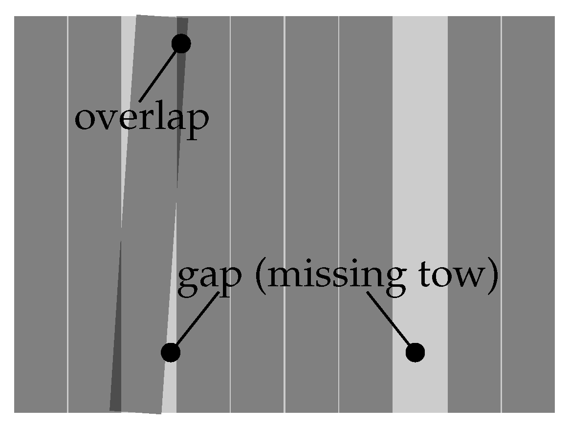
- Primary imperfections might promote secondary imperfections (e.g., a positioning deviation of the fiber material causes gaps and overlaps occurring within the ply).
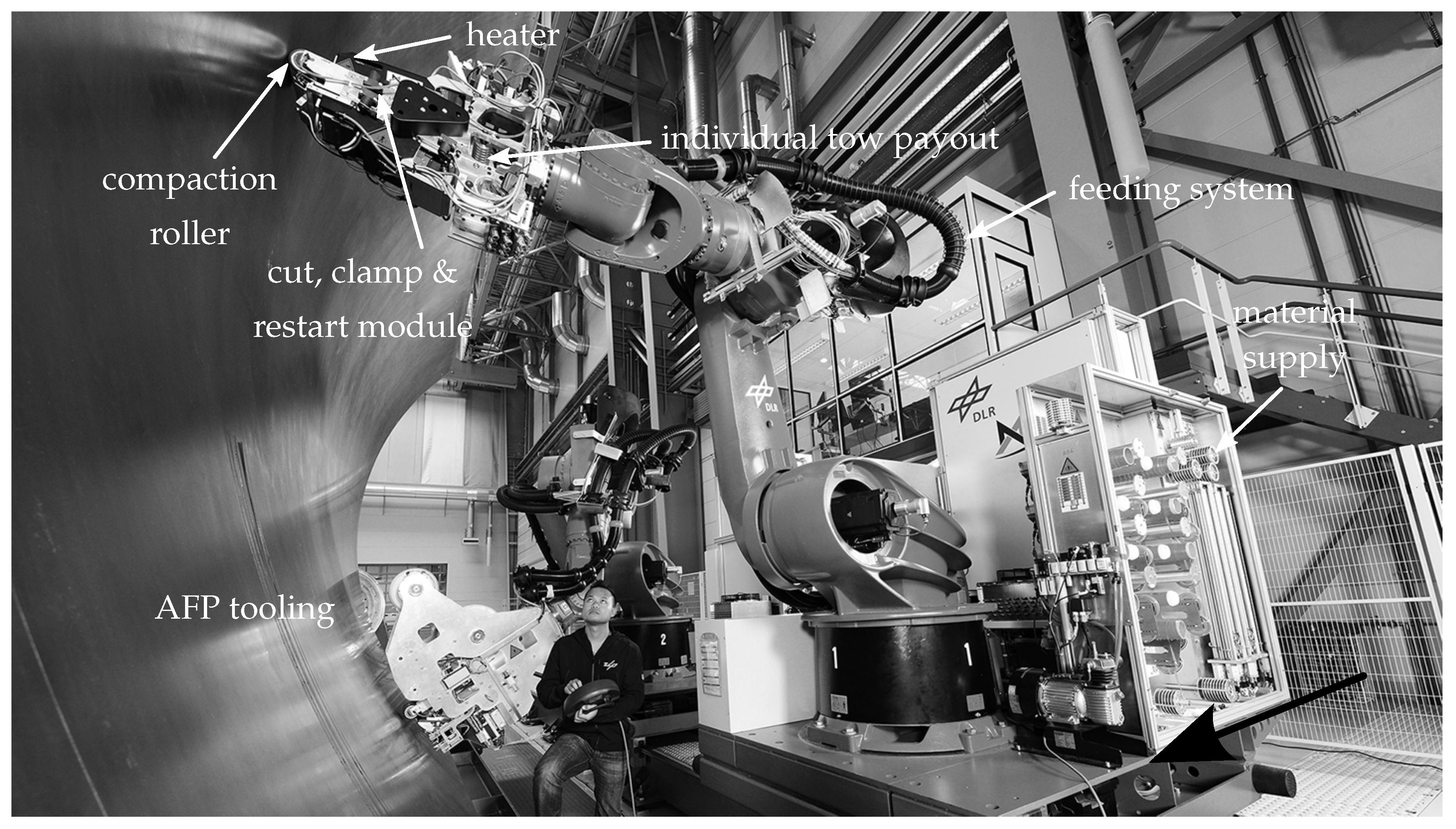
- an industrial robot [11] carrying the storage head,
- a supply of material, with cooling where necessary, to prevent premature ageing of the material and to facilitate material handling,
- a material feed, for the controlled guidance of the fiber material from the material supply to the depositing head,
- a computer program for generating input data for the ATL/AFP system and for carrying out process simulations.
3. Modelling, Analysis and Evaluation of AFP Structures with Gaps and Overlaps
4. Conclusions
- The periodic displacement boundary conditions frequently used for the homogenization of microheterogeneities impose a periodicity of the field variables (stresses and strains). However, the gaps and overlaps considered occur aperiodically in the laminate and the structure.
- The periodic displacement boundary conditions frequently used for homogenization of microheterogeneities couple degrees of freedom at the boundaries of the representative element. The geometry may violate the requirement for opposite normal vectors of the edges [119] due to the presence of gaps and overlaps in the laminate.
- The scale separation usually ensures the representativeness of the homogenized material properties. However, there is no scale separation for gaps and overlaps, since the geometric dimensions of these imperfections correspond to the size scale of the considered material section.
- The structural-mechanical effects of isolated gaps and overlaps are marginal. The strength properties of a laminate are significantly affected as soon as these imperfections emerge in a concentrated and combined manner.
- The impact of gaps and overlaps on the strength properties depends on various factors. Major determinants are the laminate configuration, location of imperfections in the laminate and loading conditions.
- For stiffness-driven phenomena at the structural level, gaps and overlaps are of little relevance due to their small influence on the stiffness properties.
- Fiber waviness at the edges of gaps and overlaps promote damage initiation and facilitate damage propagation.
- On a structural level, material and laminate properties are locally adapted. Material knock-down factors (KDF) are used to map the effect of gaps and overlaps. They are derived by means of a homogenization approach [113].
- The majority of publications in the field of ATL, AFP and VSCL structures address solely stiffness related aspects of gaps and overlaps. There are just a few works investigating the modelling aspects of gaps and overlaps in terms of residual laminate strength.
- Only a few failure criteria have so far been used to determine the residual strength properties of imperfect laminates. Researchers mostly apply either limit (maximum stress) or interaction criteria (Tsai-Wu, Tsai-Hill, Hoffman, Christensen) to evaluate damage initiation in laminates with fiber waviness. Given the large number of failure criteria available, it is unclear in which range the failure predictions vary (cf. Nakayasu and Maekawa [121]). The aim is to derive the reliability of the failure initiation prediction.
- In contrast to the homogenized elastic properties, the residual strength properties are not derived from averaging, but from local stress states. On this basis, material efforts of the individual layers are determined, which are used to evaluate the laminate with regard to first-ply failure. The choice of the model boundary conditions and the failure criterion can have a considerable influence on the calculated material efforts. It has to be checked how large this effect is and in which form it is expressed.
“Without sufficient analysis and a test database to cover commonly allowed manufacturing defects, damages, and repairs, engineers are often forced to either adopt conservative assumptions (part rejections or expensive repairs) or generate the data as it is needed (leading to down time and associated cost or lost revenue).”(F. Abdi, [1] (S. 150))
Funding
Conflicts of Interest
Abbreviations
| 2D | Two-dimensional |
| 3D | Three-dimensional |
| AFP | Automated Fiber Placement |
| ATL | Automated Tape Laying |
| CAD | Computer Aided Design |
| CAE | Computer Aided Engineering |
| CNC | Computer Numeric Control |
| FEM | Finite Element Method |
| FIPAM | FIber PAths for Manufacturing |
| FSDT | First order Shear Deformation Theory |
| FW | Filament Winding |
| KDF | Knock-Down Factor |
| LaRC | Langley Research Center |
| LDT | Laminate Definition Tool |
| NLR | Netherlands Aerospace Centre |
| OEM | Original Equipment Manufacturer |
| VSC | Variable Stiffness Composite |
| VSCL | Variable Stiffness Composite Laminate |
References
- Abdi, F.; Surdenas, J.; Munir, N.; Housner, J.; Keshavanarayana, R. Computational Approach Toward Advanced Composite Material Qualification and Structural Certification. In Virtual Testing and Predictive Modeling; Springer: Boston, MA, USA, 2009; Chapter 6; pp. 137–185. [Google Scholar] [CrossRef]
- De Luca, A.; Caputo, F. A review on analytical failure criteria for composite materials. AIMS Mater. Sci. 2017, 4, 1165–1185. [Google Scholar] [CrossRef]
- Degenhardt, R.; Kling, A.; Bethge, A.; Orf, J.; Kärger, L.; Zimmermann, R.; Rohwer, K.; Calvi, A. Investigations on imperfection sensitivity and deduction of improved knock-down factors for unstiffened CFRP cylindrical shells. Compos. Struct. 2010, 92, 1939–1946. [Google Scholar] [CrossRef]
- Wille, T.; Kärger, L.; Hein, R. Composite Process Chain Towards As-Built Design; Springer: Braunschweig, Germany, 2012; pp. 199–210. [Google Scholar] [CrossRef]
- Rudberg, T.; Nielson, J.; Henscheid, M.; Cemenska, J. Improving AFP Cell Performance. SAE Int. J. Aerosp. 2014, 7, 317–321. [Google Scholar] [CrossRef]
- Maass, D. Progress in automated ply inspection of AFP layups. Reinf. Plast. 2015, 59, 242–245. [Google Scholar] [CrossRef]
- Bannister, M. Challenges for composites into the next millennium—A reinforcement perspective. Compos. Part A Appl. Sci. Manuf. 2001, 32, 901–910. [Google Scholar] [CrossRef]
- Shirinzadeh, B.; Foong, C.W.; Tan, B.H. Robotic fibre placement process planning and control. Assem. Autom. 2000, 20, 313–320. [Google Scholar] [CrossRef]
- Olsen, H.B.; Craig, J.J. Automated composite tape lay-up using robotic devices. In Proceedings of the IEEE International Conference on Robotics and Automation, Atlanta, GA, USA, 2–6 May 1993; pp. 291–297. [Google Scholar] [CrossRef]
- Grimshaw, M.N.; Grant, C.G.; Diaz, J.M.L. Advanced technology tape laying for affordable manufacturing of large composite structures. In Proceedings of the International Sampe Symposium and Exhibition, Long Beach, CA, USA, 6–10 May 2001; pp. 1–11. [Google Scholar]
- Lukaszewicz, D.H.J.A. Optimisation of High-Speed Automated Layup of Thermoset Carbon-Fibre Preimpregnates. Ph.D. Thesis, University of Bristol, Bristol, UK, 2011. [Google Scholar]
- Hinrichsen, J.; Bautista, C. The challenge of reducing both airframe weight and manufacturing cost. Air Space Eur. 2001, 3, 119–121. [Google Scholar] [CrossRef]
- Thomas, J. The A380 programme—The big task for Europe’s aerospace industry. Air Space Eur. 2001, 3, 35–39. [Google Scholar] [CrossRef]
- Grant, C. Automated processes for composite aircraft structure. Ind. Robot Int. J. 2006, 33, 117–121. [Google Scholar] [CrossRef]
- Marsden, C.; Fews, R.; Oldroyd, P.; Yousefpour, A. Design for Manufacturing—One-Piece, Fibre-Placed Composite Helicopter Tailboom. IOP Conf. Ser. Mater. Sci. Eng. 2011, 1–8. [Google Scholar] [CrossRef]
- Lukaszewicz, D.H.J.A.; Ward, C.; Potter, K.D. The engineering aspects of automated prepreg layup: History, present and future. Compos. Part B Eng. 2012, 43, 997–1009. [Google Scholar] [CrossRef]
- Lichtinger, R.; Lacalle, J.; Hinterhoelzl, R.; Beier, U.; Drechsler, K. Simulation and experimental validation of gaps and bridging in the automated fiber placement process. Sci. Eng. Compos. Mater. 2013, 22, 1–18. [Google Scholar] [CrossRef]
- Soutis, C. Carbon fiber reinforced plastics in aircraft construction. Mater. Sci. Eng. A 2005, 412, 171–176. [Google Scholar] [CrossRef]
- Izco, L.; Isturiz, J.; Motilva, M. High Speed Tow Placement System for Complex Surfaces with Cut/ Clamp/& Restart Capabilities at 85 m/min (3350 IPM). In Proceedings of the Aerospace Manufacturing and Automated Fastening Conference and Exhibition; SAE International: Warrendale, PA, USA, 2006; pp. 1–7. [Google Scholar]
- Marsh, G. Automating aerospace composites production with fibre placement. Reinf. Plast. 2011, 55, 32–37. [Google Scholar] [CrossRef]
- Ijsselmuiden, S.T. Optimal Design of Variable Stiffness Composite Structures Using Lamination Parameters. Ph.D. Thesis, Delft University of Technology, Delft, The Netherlands, 2011. [Google Scholar]
- Fayazbakhsh, K. The Impact of Gaps and Overlaps on Variable Stiffness Composites Manufactured by Automated Fiber Placement. Ph.D. Thesis, McGill University, Montreal, QC, Canada, 2013. [Google Scholar]
- Lozano, G.G.; Tiwari, A.; Turner, C.; Astwood, S. A review on design for manufacture of variable stiffness composite laminates. Proc. Inst. Mech. Eng. Part B J. Eng. Manuf. 2015, 1–12. [Google Scholar] [CrossRef]
- Lozano, G.G.; Tiwari, A.; Turner, C. A design algorithm to model fibre paths for manufacturing of structurally optimised composite laminates. Compos. Struct. 2018. [Google Scholar] [CrossRef]
- Blom, A.W. Structural Performance of Fiber-Placed, Variable-Stiffness Composite Conical and Cylindrical Shells. Ph.D. Thesis, Delft University of Technology, Delft, The Netherlands, 2010. [Google Scholar]
- Shirinzadeh, B.; Alici, G.; Foong, C.W.; Cassidy, G. Fabrication process of open surfaces by robotic fibre placement. Robot. Comput. Integr. Manuf. 2004, 20, 17–28. [Google Scholar] [CrossRef]
- Falcó, O.S. Analysis of Process-Induced Defects on Steered-Fiber Panels for Aeronautical Applications. Ph.D. Thesis, University of Girona, Girona, Spain, 2014. [Google Scholar]
- Rouhi, M.; Ghayoor, H.; Fortin-Simpson, J.; Zacchia, T.T.; Hoa, S.V.; Hojjati, M. Design, manufacturing, and testing of a variable stiffness composite cylinder. Compos. Struct. 2018, 184, 146–152. [Google Scholar] [CrossRef]
- Perner, M.; Algermissen, S.; Keimer, R.; Monner, H.P. Avoiding defects in manufacturing processes: A review for automated CFRP production. Robot. Comput. Integr. Manuf. 2016, 38, 82–92. [Google Scholar] [CrossRef]
- Potter, K.; Khan, B.; Wisnom, M.; Bell, T.; Stevens, J. Variability, fibre waviness and misalignment in the determination of the properties of composite materials and structures. Compos. Part A Appl. Sci. Manuf. 2008, 39, 1343–1354. [Google Scholar] [CrossRef]
- Völtzer, K. Online-Prozessüberwachung von Automated Fiber Placement Prozessen auf Basis der Thermografie. Ph.D. Thesis, Gottfried Wilhelm Leibniz Universität Hannover, Hanover, Germany, 2018. [Google Scholar]
- Dell’Anno, G.; Partridge, I.; Cartie, D.; Hamlyn, A.; Chehura, E.; James, S.; Tatam, R. Automated manufacture of 3D reinforced aerospace composite structures. Int. J. Struct. Integr. 2012, 3, 22–40. [Google Scholar] [CrossRef]
- Krombholz, C.; Kruse, F.; Wiedemann, M. GroFi: Large-scale fiber placement research facility. J. Large-Scale Res. Facil. JLSRF 2016, 2, 1–4. [Google Scholar] [CrossRef]
- Denkena, B.; Schmidt, C.; Weber, P. Automated Fiber Placement Head for Manufacturing of Innovative Aerospace Stiffening Structures. Procedia Manuf. 2016, 6, 96–104. [Google Scholar] [CrossRef]
- Schmidt, C.; Denkena, B.; Völtzer, K.; Hocke, T. Thermal Image-based Monitoring for the Automated Fiber Placement Process. Procedia CIRP 2017, 62, 27–32. [Google Scholar] [CrossRef]
- DeVlieg, R.; Jeffries, K.; Vogeli, P. High-Speed Fiber Placement on Large Complex Structures. In Aerospace Technology Conference and Exposition; SAE International: Warrendale, PA, USA, 2007; pp. 1–5. [Google Scholar] [CrossRef]
- Park, S.Y.; Choi, W.J. Production Control Effect on Composite Material Quality and Stability for Aerospace Usage. In Advanced Composite Materials: Properties and Applications; De Gruyter Open: Warsaw, Poland, 2017; Chapter 3. [Google Scholar] [CrossRef]
- Smith, R.P.; Qureshi, Z.; Scaife, R.J.; El-Dessouky, H.M. Limitations of processing carbon fibre reinforced plastic/polymer material using automated fibre placement technology. J. Reinf. Plast. Compos. 2016, 35, 1527–1542. [Google Scholar] [CrossRef]
- Lopes, C.S. Damage and Failure of Non-Conventional Composite Laminates. Ph.D. Thesis, Delft University of Technology, Delft, The Netherlands, 2009. [Google Scholar]
- Nik, M.A.; Fayazbakhsh, K.; Pasini, D.; Lessard, L. Optimization of variable stiffness composites with embedded defects induced by Automated Fiber Placement. Compos. Struct. 2014, 107, 160–166. [Google Scholar] [CrossRef]
- Mesogitis, T.S.; Skordos, A.A.; Long, A.C. Uncertainty in the manufacturing of fibrous thermosetting composites: A review. Compos. Part A Appl. Sci. Manuf. 2014, 57, 67–75. [Google Scholar] [CrossRef]
- Karkkainen, R.L.; Sankar, B.; Tzeng, J.T. Strength prediction of multi-layer plain weave textile composites using the direct micromechanics method. Compos. Part B Eng. 2007, 38, 924–932. [Google Scholar] [CrossRef]
- Pankow, M.; Waas, A.M.; Yen, C.F.; Ghiorse, S. A new lamination theory for layered textile composites that account for manufacturing induced effects. Compos. Part A Appl. Sci. Manuf. 2009, 40, 1991–2003. [Google Scholar] [CrossRef]
- Xu, Y.; Zhang, W.; Bassir, D. Stress analysis of multi-phase and multi-layer plain weave composite structure using global/local approach. Compos. Struct. 2010, 92, 1143–1154. [Google Scholar] [CrossRef]
- Matveev, M.Y.; Schubel, P.J.; Long, A.C.; Jones, I.A. Understanding the buckling behaviour of steered tows in Automated Dry Fibre Placement (ADFP). Compos. Part A Appl. Sci. Manuf. 2016, 90, 451–456. [Google Scholar] [CrossRef]
- Bakhshi, N.; Hojjati, M. An experimental and simulative study on the defects appeared during tow steering in automated fiber placement. Compos. Part A Appl. Sci. Manuf. 2018, 113, 122–131. [Google Scholar] [CrossRef]
- Sutcliffe, M.P.F.; Lemanski, S.L.; Scott, A.E. Measurement of fibre waviness in industrial composite components. Compos. Sci. Technol. 2012, 72, 2016–2023. [Google Scholar] [CrossRef]
- Sawicki, A.J.; Minguett, P. The effect of intraply overlaps and gaps upon the compression strength of composite laminates. In Proceedings of the 39th AIAA/ASME/ASCE/AHS/ASC Structures, Structural Dynamics, and Materials Conference and Exhibit, Long Beach, CA, USA, 20–23 April 1998; pp. 744–754. [Google Scholar] [CrossRef]
- Gruber, M.; Lamontia, M.A.; Waibel, B.J. Automated fabrication processes for large composite aerospace structures: A trade study. In Proceedings of the 46 th International SAMPE Symposium and Exhibition, Long Beach, CA, USA, 6–10 May 2001; pp. 1987–1997. [Google Scholar]
- Lamontia, M.A.; Gruber, M.B.; Waibel, B.J.; Cope, R.D.; Funck, S.B.; Systems, A.; Drive, S. Contoured tape laying and fiber placement heads for automated fiber placement of large composite aerospace structures. In Proceedings of the 34 th International SAMPE Technical Conference, Baltimore, MD, USA, 4–7 November 2002; pp. 1–15. [Google Scholar]
- Li, X.; Hallett, S.R.; Wisnom, M.R. Modelling the effect of gaps and overlaps in automated fibre placement (AFP)-manufactured laminates. Sci. Eng. Compos. Mater. 2015, 22, 115–129. [Google Scholar] [CrossRef]
- Xie, N.; Smith, R.A.; Mukhopadhyay, S.; Hallett, S.R. A numerical study on the influence of composite wrinkle defect geometry on compressive strength. Mater. Des. 2018, 140, 7–20. [Google Scholar] [CrossRef]
- Seon, G.; Nikishkov, Y.; Makeev, A. Structures Perspective for Strength and Fatigue Prognosis in Composites with Manufacturing Irregularities. J. Am. Helicopter Soc. 2015, 60, 1–10. [Google Scholar] [CrossRef]
- Wang, J.; Potter, K.D.; Hazra, K.; Wisnom, M.R. Experimental fabrication and characterization of out-of-plane fiber waviness in continuous fiber-reinforced composites. J. Compos. Mater. 2012, 46, 2041–2053. [Google Scholar] [CrossRef]
- Li, X.; Hallett, S.R.; Wisnom, M.R. Modelling the effect of gaps and overlaps in automated fibre placement (AFP)-manufactured laminates. In Proceedings of the 19th International Conference on Composite Materials (ICCM19), Montreal, QC, Canada, 28 July–2 August 2013; pp. 1–15. [Google Scholar]
- Lan, M.; Cartié, D.; Davies, P.; Baley, C. Microstructure and tensile properties of carbon-epoxy laminates produced by automated fibre placement: Influence of a caul plate on the effects of gap and overlap embedded defects. Compos. Part A Appl. Sci. Manuf. 2015, 78, 124–134. [Google Scholar] [CrossRef]
- Lan, M.; Cartié, D.; Davies, P.; Baley, C. Influence of embedded gap and overlap fiber placement defects on the microstructure and shear and compression properties of carbon-epoxy laminates. Compos. Part A Appl. Sci. Manuf. 2016, 82, 198–207. [Google Scholar] [CrossRef]
- Lukaszewicz, D.H.J.A.; Potter, K. Through-thickness compression response of uncured prepreg during manufacture by automated layup. Proc. Inst. Mech. Eng. Part B J. Eng. Manuf. 2011, 226, 193–202. [Google Scholar] [CrossRef]
- Adams, D.O.; Bell, S.J. Compression strength reductions in composite laminates due to multiple-layer waviness. Compos. Sci. Technol. 1995, 53, 207–212. [Google Scholar] [CrossRef]
- Hsiao, H.M.; Daniel, I.M. Effect of fiber waviness on stiffness and strength reduction of unidirectional composites under compressive loading. Compos. Sci. Technol. 1996, 56, 581–593. [Google Scholar] [CrossRef]
- Marrouze, J.P.; Housner, J.; Abdi, F. Effect of Manufacturing Defects and Their Uncertainties on Strength and Stability of Stiffened Panels. In Proceedings of the 19th International Conference on Composite Materials (ICCM19), Montreal, QC, Canada, 28 July–2 August 2013; pp. 1–10. [Google Scholar]
- Khattab, I.A. A Novel Numerical Approach and Experimental Study on the Waviness Defects in Composite Structures. Ph.D. Thesis, Otto-von-Guericke-Universität Magdeburg, Magdeburg, Germany, 2013. [Google Scholar]
- Khattab, I.A.; Kreikemeier, J.; Abdelhadi, N.S. Manufacturing of CFRP specimens with controlled out-of-plane waviness. CEAS Aeronaut. J. 2014, 5, 85–93. [Google Scholar] [CrossRef]
- Mukhopadhyay, S.; Jones, M.I.; Hallett, S.R. Tensile failure of laminates containing an embedded wrinkle; numerical and experimental study. Compos. Part A Appl. Sci. Manuf. 2015, 77, 219–228. [Google Scholar] [CrossRef]
- Mukhopadhyay, S.; Jones, M.I.; Hallett, S.R. Compressive failure of laminates containing an embedded wrinkle; experimental and numerical study. Compos. Part A Appl. Sci. Manuf. 2015, 73, 132–142. [Google Scholar] [CrossRef]
- Jegley, D.; Tatting, B.F.; Gürdal, Z. Tow-Steered Panels with Holes Subjected to Compression or Shear Loading. In Proceedings of the 446th AIAA/ASME/ASCE/AHS/ASC Structures, Structural Dynamics and Materials Conference; American Institute of Aeronautics and Astronautics: Reston, VA, USA, 2005; pp. 1–14. [Google Scholar] [CrossRef]
- Marouene, A.; Boukhili, R.; Chen, J.; Yousefpour, A. Effects of gaps and overlaps on the buckling behavior of an optimally designed variable-stiffness composite laminates—A numerical and experimental study. Compos. Struct. 2016, 140, 556–566. [Google Scholar] [CrossRef]
- Tatting, B.F.; Gürdal, Z. Automated Finite Element Analysis of Elastically-Tailored Plates (RP); Technical Report; National Aeronautics and Space Administration (NASA): Hampton, VA, USA, 2003.
- Kim, B.C.; Hazra, K.; Weaver, P.M.; Potter, K.D. Limitations of fibre placement techniques for variable angle tow composites and their process-induced defects. In Proceedings of the 18th International Conference on Composite Materials (ICMM18), Jeju, Korea, 21–26 August 2011; pp. 1–6. [Google Scholar]
- Fayazbakhsh, K.; Pasini, D.; Lessard, L.; Chen, J.; Yousefpour, A. Design and Manufacturing of Optimum Variable Stiffness Laminates. In Proceedings of the 19th International Conference on Composite Materials (ICCM19), Montreal, QC, Canada, 28 July–2 August 2013; pp. 1–8. [Google Scholar]
- Sawicki, A.; Schulze, E.; Fitzwater, L.; Harris, K. Structural Qualification of V-22 EMD Tow-Placed Aft Fuselage. In Proceedings of the American Helicopter Society 51st Annual Forum, Fort Worth, TX, USA, 9–11 May 1995; pp. 1641–1654. [Google Scholar]
- Croft, K.; Lessard, L.; Pasini, D.; Hojjati, M.; Chen, J.; Yousefpour, A. Experimental study of the effect of automated fiber placement induced defects on performance of composite laminates. Compos. Part A Appl. Sci. Manuf. 2011, 42, 484–491. [Google Scholar] [CrossRef]
- Falcó, O.S.; Lopes, C.S.; Mayugo, J.A.; Gascons, N.; Renart, J. Effect of tow-drop gaps on the damage resistance and tolerance of Variable-Stiffness Panels. Compos. Struct. 2014, 116, 94–103. [Google Scholar] [CrossRef]
- Falcó, O.S.; Mayugo, J.A.; Lopes, C.S.; Gascons, N.; Costa, J. Variable-stiffness composite panels: Defect tolerance under in-plane tensile loading. Compos. Part A Appl. Sci. Manuf. 2014, 63, 21–31. [Google Scholar] [CrossRef]
- Elsherbini, Y.M.; Hoa, S.V. Experimental and numerical investigation of the effect of gaps on fatigue behavior of unidirectional carbon/epoxy automated fiber placement laminates. J. Compos. Mater. 2016, 1–14. [Google Scholar] [CrossRef]
- Marouene, A.; Legay, P.; Boukhili, R. Experimental and numerical investigation on the open-hole compressive strength of AFP composites containing gaps and overlaps. J. Compos. Mater. 2017, 1–16. [Google Scholar] [CrossRef]
- Hale, R.D.; Moon, R.S.; Lim, K.; Schueler, K.; Yoder, A.; Singh, H. Integrated Design and Analysis Tools for Reduced Weight, Affordable Fiber Steered Composites; Technical Report; University of Kansas Center for Research: Lawrence, KS, USA, 2004. [Google Scholar]
- Woigk, W.; Hallett, S.R.; Jones, M.I.; Kuhtz, M.; Hornig, A.; Gude, M. Experimental investigation of the effect of defects in Automated Fibre Placement produced composite laminates. Compos. Struct. 2018, 201, 1004–1017. [Google Scholar] [CrossRef]
- Rakhshbahar, M.; Sinapius, M. A Novel Approach: Combination of Automated Fiber Placement (AFP) and Additive Layer Manufacturing (ALM). J. Compos. Sci. 2018, 2, 42. [Google Scholar] [CrossRef]
- Denkena, B.; Schmidt, C.; Völtzer, K.; Hocke, T. Thermographic online monitoring system for Automated Fiber Placement processes. Compos. Part B Eng. 2016, 97, 239–243. [Google Scholar] [CrossRef]
- Zambal, S.; Eitzinger, C.; Clarke, M.; Klintworth, J.; Mechin, P.Y. A digital twin for composite parts manufacturing—Effects of defects analysis based on manufacturing data. In Proceedings of the IEEE 16th International Conference on Industrial Informatics (INDIN), Porto, Portugal, 18–20 July 2018; pp. 803–808. [Google Scholar]
- Ribeiro, P.; Akhavan, H.; Teter, A.; Warminski, J. A review on the mechanical behaviour of curvilinear fibre composite laminated panels. J. Compos. Mater. 2014, 48, 2761–2777. [Google Scholar] [CrossRef]
- Fagiano, C. Computational Modeling of Tow-Placed Composite Laminates with Fabrication Features. Ph.D. Thesis, Delft University of Technology, Delft, The Netherlands, 2010. [Google Scholar]
- Lopes, C.S.; Gürdal, Z.; Camanho, P.P. Variable-stiffness composite panels: Buckling and first-ply failure improvements over straight-fibre laminates. Comput. Struct. 2008, 86, 897–907. [Google Scholar] [CrossRef]
- Beakou, A.; Cano, M.; Le Cam, J.B.; Verney, V. Modelling slit tape buckling during automated prepreg manufacturing: A local approach. Compos. Struct. 2011, 93, 2628–2635. [Google Scholar] [CrossRef]
- Zhao, C.; Xiao, J.; Huang, W.; Huang, X.; Gu, S. Layup quality evaluation of fiber trajectory based on prepreg tow deformability for automated fiber placement. J. Reinf. Plast. Compos. 2016, 35, 1576–1585. [Google Scholar] [CrossRef]
- Nagendra, S.; Kodiyalam, S.; Davis, J.; Parthasarathy, V. Optimization of tow fiber paths for composite design. In Proceedings of the 36th Structures, Structural Dynamics and Materials Conference, New Orleans, LA, USA, 10–13 April 1995; pp. 1–11. [Google Scholar] [CrossRef]
- Lukaszewicz, D.H.J.A.; Potter, K.D.; Eales, J. A concept for the in situ consolidation of thermoset matrix prepreg during automated lay-up. Compos. Part B Eng. 2013, 45, 538–543. [Google Scholar] [CrossRef]
- Hulcher, A.B.; McGowan, M.; Grimsley, W. Processing and Testing of Thermoplastic Composite Cylindrical Shells Fabricated By Automated Fiber Placement. In Proceedings of the 47 th International SAMPE Symposium and Exhibition, Long Beach, CA, USA, 12–16 May 2002; pp. 1–15. [Google Scholar]
- Ranganathan, S.; Advani, S.G.; Lamontia, M.A. A Non-Isothermal Process Model for Consolidation and Void Reduction during In-Situ Tow Placement of Thermoplastic Composites. J. Compos. Mater. 1995, 29, 1040–1062. [Google Scholar] [CrossRef]
- Pitchumani, R.; Ranganathan, S.; Don, R.C.; Gillespie, J.W.; Lamontia, M.A. Analysis of transport phenomena governing interfacial bonding and void dynamics during thermoplastic tow-placement. Int. J. Heat Mass Transf. 1996, 39, 1883–1897. [Google Scholar] [CrossRef]
- Pitchumani, R.; Gillespie, J.W.; Lamontia, M.A. Design and Optimization of a Thermoplastic Tow-Placement Process with In-Situ Consolidation. J. Compos. Mater. 1997, 31, 244–275. [Google Scholar] [CrossRef]
- Tatting, B.F. Analysis and Design of Variable Stiffness Composite Cylinders. Ph.D. Thesis, Virginia Polytechnic Institute and State University, Blacksburg, VA, USA, 1998. [Google Scholar]
- Khan, M.A.; Mitschang, P.; Schledjewski, R. Parametric study on processing parameters and resulting part quality through thermoplastic tape placement process. J. Compos. Mater. 2012, 47, 485–499. [Google Scholar] [CrossRef]
- Lukaszewicz, D.H.J.A.; Potter, K.D. The internal structure and conformation of prepreg with respect to reliable automated processing. Compos. Part A Appl. Sci. Manuf. 2011, 42, 283–292. [Google Scholar] [CrossRef]
- Lopes, C.S.; Camanho, P.P.; Gürdal, Z.; Tatting, B.F. Progressive damage analysis of tow-steered composite panels in postbuckling. In Proceedings of the 16th International Conference on Composite Materials (ICCM16), Kyoto, Japan, 8–13 July 2007; pp. 1–10. [Google Scholar]
- Lopes, C.S.; Camanho, P.P.; Gürdal, Z.; Tatting, B.F. Progressive failure analysis of tow-placed, variable-stiffness composite panels. Int. J. Solids Struct. 2007, 44, 8493–8516. [Google Scholar] [CrossRef]
- Lopes, C.S.; Camanho, P.P.; Gürdal, Z. Variable-Stiffness Composite Panels: Effects of Stiffness Variation on the Buckling and Failure. In Proceedings of the 7th EUROMECH Solid Mechanics Conference (ESMC2009), Lisbon, Portugal, 7–11 September 2009; pp. 1–13. [Google Scholar]
- Lopes, C.S.; Camanho, P.P.; Gürdal, Z. Tailoring for Strength of Steered-Fiber Composite Panels with Cutouts. In Proceedings of the 51st AIAA/ASME/ASCE/AHS/ASC Structures, Structural Dynamics, and Materials Conference, Orlando, FL, USA, 12–15 April 2010; pp. 1–8. [Google Scholar] [CrossRef]
- Ijsselmuiden, S.T.; Abdalla, M.M.; Gürdal, Z. Thermomechanical Design Optimization of Variable Stiffness Composite Panels for Buckling. J. Therm. Stress. 2010, 33, 977–992. [Google Scholar] [CrossRef]
- Wu, K.C.; Tatting, B.F.; Smith, B.; Stevens, R.; Occhipinti, G.; Swift, J.; Achary, D.; Thornburgh, R. Design and Manufacturing of Tow-Steered Composite Shells Using Fiber Placement. In Proceedings of the 50th AIAA/ASME/ASCE/AHS/ASC Structures, Structural Dynamics, and Materials Conference, Palm Springs, CA, USA, 4–7 May 2009; pp. 1–18. [Google Scholar] [CrossRef]
- Aized, T.; Shirinzadeh, B. Robotic fiber placement process analysis and optimization using response surface method. Int. J. Adv. Manuf. Technol. 2011, 55, 393–404. [Google Scholar] [CrossRef]
- Noevere, A.; Collier, C. Mapping Manufacturing Data for Stress Analysis of Automated Fiber Placement Structures. In Proceedings of the AIAA/ASCE/AHS/ASC Structures, Structural Dynamics, and Materials Conference, Kissimmee, FL, USA, 8–12 January 2018; pp. 1–21. [Google Scholar] [CrossRef]
- Cairns, D.S.; Ilcewicz, L.B.; Walker, T. Response of Automated Tow Placed Laminates to Stress Concentrations. In Proceedings of the Third NASA Advanced Composites Technology Conference (ACT), Long Beach, CA, USA, 8–11 June 1993; pp. 1–15. [Google Scholar]
- Tatting, B.F.; Gürdal, Z. Design and Manufacture of Elastically Tailored Tow Placed Plates; Technical Report; National Aeronautics and Space Administration (NASA): Hampton, VA, USA, 2002.
- Blom, A.W.; Lopes, C.S.; Kromwijk, P.J.; Gürdal, Z.; Camanho, P.P. A Theoretical Model to Study the Influence of Tow-drop Areas on the Stiffness and Strength of Variable-stiffness Laminates. J. Compos. Mater. 2009, 43, 403–425. [Google Scholar] [CrossRef]
- Falcó, O.S.; Mayugo, J.A.; Lopes, C.S.; Gascons, N.; Turon, A.; Costa, J. Variable-stiffness composite panels: As-manufactured modeling and its influence on the failure behavior. Compos. Part B Eng. 2014, 56, 660–669. [Google Scholar] [CrossRef]
- Falcó, O.S.; Lopes, C.S.; Naya, F.; Sket, F.; Maimí, P.; Mayugo, J.A. Modelling and simulation of tow-drop effects arising from the manufacturing of steered-fibre composites. Compos. Part A Appl. Sci. Manuf. 2017, 93, 59–71. [Google Scholar] [CrossRef]
- Fayazbakhsh, K.; Nik, M.A.; Pasini, D.; Lessard, L. Defect layer method to capture effect of gaps and overlaps in variable stiffness laminates made by Automated Fiber Placement. Compos. Struct. 2013, 97, 245–251. [Google Scholar] [CrossRef]
- Akbarzadeh, A.H.; Nik, M.A.; Pasini, D. The role of shear deformation in laminated plates with curvilinear fiber paths and embedded defects. Compos. Struct. 2014, 118, 217–227. [Google Scholar] [CrossRef]
- Dang, T.D.; Hallet, S.R.; Kim, B.C.; Cahain, Y.L.; Butler, R.; Liu, W. Modelling of as manufactured geometry for prediction of impact and compression after impact behaviour of variable angle tow laminates. J. Compos. Mater. 2015, 49, 1423–1438. [Google Scholar] [CrossRef]
- Heinecke, F.; Brink, W.V.d.; Wille, T. Assessing the structural response of automated fibre placement composite structures with gaps and overlaps by means of numerical approaches. In Proceedings of the 20th International Conference on Composite Materials, Copenhagen, Denmark, 19–24 July 2015. [Google Scholar]
- Heinecke, F.; Wille, T. In-situ structural evaluation during the fibre deposition process of composite manufacturing. CEAS Aeronaut. J. 2018. [Google Scholar] [CrossRef]
- Soriano, A.; Díaz, J. Failure analysis of variable stiffness composite plates using continuum damage mechanics models. Compos. Struct. 2018, 184, 1071–1080. [Google Scholar] [CrossRef]
- Ostergaard, M.G.; Ibbotson, A.R.; Roux, O.L.; Prior, A.M. Virtual testing of aircraft structures. CEAS Aeronaut. J. 2011, 1, 83–103. [Google Scholar] [CrossRef]
- Llorca, J.; Gonzalez, C.; Molina-Aldareguia, J.M.; Segurado, J.; Seltzer, R.; Sket, F.; Rodriguez, M.; Sadaba, S.; Munoz, R.; Canal, L.P. Multiscale modeling of composite materials: A roadmap towards virtual testing. Adv. Mater. 2011, 23, 5130–5147. [Google Scholar] [CrossRef]
- Llorca, J.; Gonzalez, C.; Molina-Aldareguia, J.M.; Lopes, C.S. Multiscale Modeling of Composites: Toward Virtual Testing … and Beyond. JOM 2013, 65, 215–225. [Google Scholar] [CrossRef]
- Kärger, L.; Kling, A. As-built FE simulation of advanced fibre placement structures based on manufacturing data. Compos. Struct. 2013, 100, 104–112. [Google Scholar] [CrossRef]
- Glüge, R.; Weber, M.; Bertram, A. Comparison of spherical and cubical statistical volume elements with respect to convergence, anisotropy, and localization behavior. Comput. Mater. Sci. 2012, 63, 91–104. [Google Scholar] [CrossRef]
- Karami, G.; Garnich, M.R. Effective moduli and failure considerations for composites with periodic fiber waviness. Compos. Struct. 2005, 67, 461–475. [Google Scholar] [CrossRef]
- Nakayasu, H.; Maekawa, Z. A comparative study of failure criteria in probabilistic fields and stochastic failure envelopes of composite materials. Reliab. Eng. Syst. Saf. 1997, 56, 209–220. [Google Scholar] [CrossRef]
- Hassan, M.H.; Othman, A.R.; Kamaruddin, S. A review on the manufacturing defects of complex-shaped laminate in aircraft composite structures. Int. J. Adv. Manuf. Technol. 2017, 91, 4081–4094. [Google Scholar] [CrossRef]
- Belnoue, J.P.; Mesogitis, T.; Nixon-Pearson, O.J.; Kratz, J.; Ivanov, D.S.; Partridge, I.K.; Potter, K.D.; Hallett, S.R. Understanding and predicting defect formation in automated fibre placement pre-preg laminates. Compos. Part A Appl. Sci. Manuf. 2017, 102, 196–206. [Google Scholar] [CrossRef]
- Bogetti, T.A.; Gillespie, J.W.; Lamontia, M.A. Influence of Ply Waviness on the Stiffness and Strength Reduction on Composite Laminates. J. Thermoplast. Compos. Mater. 1992, 5, 344–369. [Google Scholar] [CrossRef]


| Manufacturer | Type | Components |
|---|---|---|
| Boeing [10,11,19,20,21,22] | 777, 787 V-22 Osprey | wing, empennage, fuselage |
| Airbus [9,10,20,21,22] | A319/A320/A321, A330/A340, A350, A380, A400M | empennage, wing, fuselage |
| Bombardier [20] | C-Series | fuselage |
| Fairchild Dornier [10] | Do 728 | empennage |
| Gulfstream Aerospace [10] | Gulfstream IV | wing |
| Dassault Aviation [10] | Dassault Falcon | empennage |
| Hawker Beechcraft Corporation [11,20] | Premier 1, Hawker 4000 | fuselage |
| Northrop [9,10] | B-2 | wing |
| Grumman Aerospace Corporation [10] | A-6 Intruder | wing |
| Vought Aircaft [10,11,21] | C-17 | empennage |
| Lockheed Martin [10,11,20] | F-22, F-35, C-130 | wing, empennage |
| Eurofighter [10] | Eurofighter Typhoon | wing |
| Secondary Imperfection | |||||||||||
|---|---|---|---|---|---|---|---|---|---|---|---|
| Type I | Type II | Type III | Type IV | Type V | Type VI | Type VII | Type VIII | Type IX | Type X | ||
| Primary Imperfection | Type I | • | • | • | |||||||
| Type II | • | • | • | ||||||||
| Type III | • | ||||||||||
| Type IV | • | • | • | ||||||||
| Type V | • | • | • | • | |||||||
| Type VI | • | • | |||||||||
| Type VII | • | • | • | • | |||||||
| Type VIII | • | • | • | ||||||||
| Type IX | - | - | - | - | - | - | - | - | - | ||
| Type X | • | • | • | ||||||||
© 2019 by the authors. Licensee MDPI, Basel, Switzerland. This article is an open access article distributed under the terms and conditions of the Creative Commons Attribution (CC BY) license (http://creativecommons.org/licenses/by/4.0/).
Share and Cite
Heinecke, F.; Willberg, C. Manufacturing-Induced Imperfections in Composite Parts Manufactured via Automated Fiber Placement. J. Compos. Sci. 2019, 3, 56. https://doi.org/10.3390/jcs3020056
Heinecke F, Willberg C. Manufacturing-Induced Imperfections in Composite Parts Manufactured via Automated Fiber Placement. Journal of Composites Science. 2019; 3(2):56. https://doi.org/10.3390/jcs3020056
Chicago/Turabian StyleHeinecke, Falk, and Christian Willberg. 2019. "Manufacturing-Induced Imperfections in Composite Parts Manufactured via Automated Fiber Placement" Journal of Composites Science 3, no. 2: 56. https://doi.org/10.3390/jcs3020056
APA StyleHeinecke, F., & Willberg, C. (2019). Manufacturing-Induced Imperfections in Composite Parts Manufactured via Automated Fiber Placement. Journal of Composites Science, 3(2), 56. https://doi.org/10.3390/jcs3020056