Article

Mechanical Properties of Cellulose Nanocrystal (CNC) Bundles: Coarse-Grained Molecular Dynamic Simulation

by
Majid G. Ramezani
* and
Behnoush Golchinfar
School of Civil Engineering, Stevens Institute of Technology, Hoboken, NJ 07030-5991, USA
*
Author to whom correspondence should be addressed.
J. Compos. Sci. 2019, 3(2), 57; https://doi.org/10.3390/jcs3020057
Submission received: 19 April 2019 / Revised: 13 May 2019 / Accepted: 27 May 2019 / Published: 3 June 2019

Abstract

:
Cellulose nanocrystals (CNCs) is a promising biodegradable nanomaterial with outstanding physical, chemical, and mechanical properties for many applications. Although aligned CNCs can self-assemble into bundles, their mechanical performance is reduced by interfacial strength between CNCs and a twisted structure. In this paper, we employ developed coarse-grained (CG) molecular dynamic (MD) simulations to investigate the influence of twist and interface energy on the tensile performance of CNC bundles. CNC bundles of different sizes (number of particles) are tested to also include the effect of size on mechanical performance. The effect of interfacial energy and twist on the mechanical performance shows that elastic modulus, strength, and toughness are more sensitive to twisted angle than interfacial energy. In addition, the effect of size on the bundle and twist on their mechanical performance revealed that both size and twist have a significant effect on the results and can reduce the strength and elastic modulus by 75% as a results of covalent bond dissociation. In addition, a comparison of the broken regions for different values of twist shows that by increasing the twist angle the crack propagates in multiple locations with a twisted shape.

1. Introduction

Cellulose is an abundant green polymer on earth mostly found in plant cell walls. Cellulose nanocrystals (CNCs) are crystalline structures that are formed by the stacking of many cellulose chains through hydrogen bonding [1]. They have gained significant attention in recent years due to their outstanding physical, mechanical, and chemical properties such as high aspect ratio, high strength, high stiffness, and active surface for surface functionalization [1,2,3,4]. Having a very active surface and high aspect ratio, aligned CNCs can easily assemble to CNC bundles [5] and be used in CNC reinforced composite materials. However, studies have shown that twisting of fibers can affect the interaction between fibers and reduce the overall performance of the bundle [6]. This is particularly important for CNCs as many studies have shown that CNCs can easily twist [7,8,9].
In the past decade, substantial efforts have been placed on employing CNCs as neat cellulose-based materials [10] or as a reinforcement element in fiber nanocomposites [11,12,13]. Many researchers employed experimental and theoretical approaches to characterize the mechanical properties of individual CNCs [14,15,16,17,18,19,20,21], bio-inspired CNCs [14,15,16,17,18,19,20,21], and CNC nanocomposite. For example, experimental and theoretical studies show that the Young modulus of a pristine CNC in the longitudinal direction is in the range of 110–200 GPa [14,21] and strength of a perfect CNC is in the range of 2–8 GPa [19,22]. While in MD simulations the focus of the study is limited to the short length and small number of CNCs, some researchers have developed coarse-grained (CG) models to overcome this limitation and provide insights on the performance of long CNCs or the assembly of many CNCs [21]. Many researchers developed CG models of CNCs with different coarsening details such as three beads [23,24,25,26] and one bead [27,28,29,30,31] per glucose ring for conformational [23,25,32], mechanical [24,26,31], and chemical properties [27,28,33]. For example, a solvent free CG model of CNC was developed to understand the transition of crystalline to amorphous [28]. Fan and Maranas, (2015), developed a unique CG model for conformational analysis of long fibrils [29]. Wu et al. (2012), used the MARTINI CG model of CNC and studied the effect of the number of chains in a CNC on the twist angle and found that CNCs with more than 36 chains broke into two parts [25]. A detailed CG model for mechanical and interfacial properties of CNC was developed to study the performance of bioinspired Bouligand and staggered structure of CNCs and it showed that the natural twist of CNCs improved the performance of materials [5]. In another study, a spring-bead model for CNC was used to study the effect of length and surface energy on the performance and CNC nanopapers [34].
In this work, we employ the developed CG model for CNC [5,17,18,35,36] to understand the effect of twisting on the strength, elastic modulus, and toughness of CNC bundles. This study helps the researchers to understand the correlation between twist angle and bundle size, and the mechanical performance for optimum design of bundle size. Although to the best of our knowledge, this is the first study on the effect of twist on the CNC bundle, there have been many studies on the carbon nanotube (CNT) bundles and yarns [6,37,38,39]. For example, MD simulations of CNT bundle under axial tension showed that twisted CNT reduces the mechanical performance [37]. A study on the twisted CNT yarn revealed that twisting could improve the interaction between tubes by increasing the interaction area [6].

2. Materials and Methods

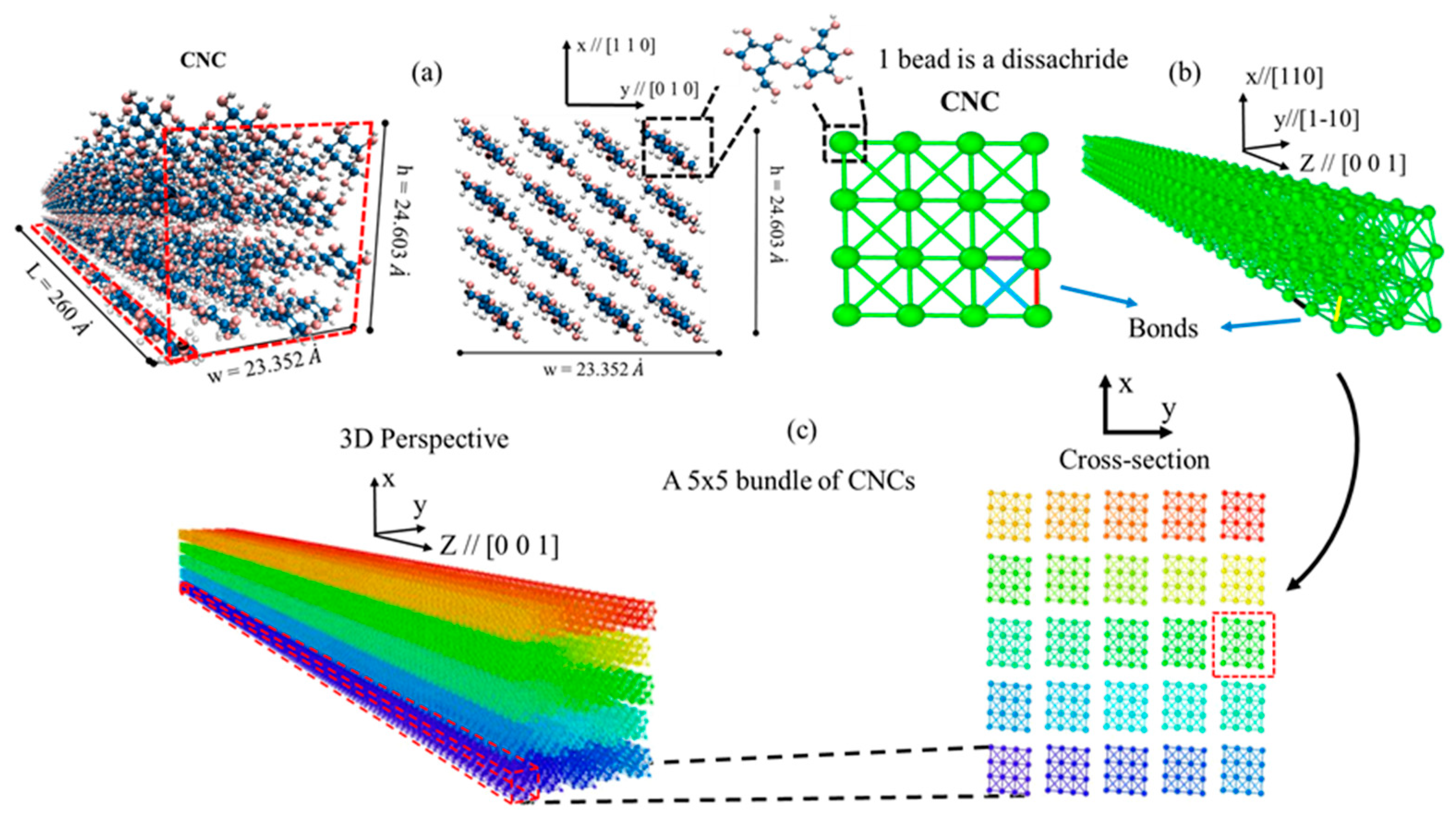
2.1. The Coarse-Grained (CG) Model for Cellulose Nanocrystals (CNC)

The idea behind coarse-graining at the atomistic scale is to save computational time and energy by reducing the number of particles involved in the simulation while maintaining the critical physics of the original model (all-atom model). The CG model used in this study had been recently developed by Shishehbor and Zavattieri (2019), for mechanical and interfacial properties of CNCs [5]. We mainly choose this model for the following reasons: (1) because it provides enough structural details of CNCs, (2) because of its tuneability of interfacial interaction between CNCs for surface functionalization, and (3) because it is available for the public through the nanoHUB toolkit [17,18]. Here we explain the key features and equations of the model, however, for more details readers are referred to the original paper [5].
Figure 1a shows 3D and cross-section views of the molecular structure for a single CNC particle, formed by stacking of many cellulose chains (β-D glucopyranose) through hydrogen bonding (h-bonding) with reported unit cell parameters of a = 7.784 Å, b = 8.201 Å, c = 10.380 Å, α = 90°, β = 90°, γ = 96.55°, at 293 K [1]. While covalent bond (also called bonded interactions) is the dominant interaction in the chain direction, the interaction between chains is mainly through Van der Waals (VdW) and h-bonding (also called nonbonded interactions) [1,7]. Previous studies suggest that the elastic modulus and strength of CNC in the chain direction ([001]) are mainly associated with covalent bonding, while VdW interactions and h-bonding have the main contributions for those properties in the lateral directions (110 and 1–10) [7,40]. In addition, for the interaction between two or more CNC particles, VdW and h-bonding are the major governing interactions. In the CG model proposed for the mechanical and interfacial properties of CNCs [5], CG beads represent disaccharide molecules, and they are connected though different in order to model the mechanical properties of a single CNC (Figure 1b). Although adding more details (6 beads per cellobiose) would provide more information, the computational costs (number of particles and timestep) would increase dramatically. The current CG model would allow us to model big systems without sacrificing mechanical properties and interfacial properties as shown by [5]. The interfacial properties, however, are modeled through nonlocal nonbonded potentials. Therefore, the total energy of the system (E) is defined through bonded (Eb) and nonbonded (Enb) interactions (Equation (1)).
E = E b + E n b
To accurately model the anisotropic mechanical properties of a single CNC in all directions, five different bonds were considered in the model and parametrized to fit the experimental and MD results. For bonded interactions, Morse potential was considered to model dissociation of interactions, and therefore the total bonded energy terms for the model is as follow:
E b ( r ) = i = 1 5 E b i ( r ) = i = 1 5 D b i [ 1 e α b i ( r r 0 b i ) ] 2
where, D, r0, and α are the parameters of Morse potential.
For nonbonded interactions Lennard-Jones (LJ) potential were considered as follow:
E n b ( r ) = 4 ϵ [ ( σ r ) 12 ( σ r ) 6 ]
where, σ is approximately the distance between two beads at equilibrium, ϵ is the energy term for LJ potential depth, and r is the distance between two beads. Figure 1c shows the assembly of 25 CNCs as a 5 × 5 CNC bundle where each particle is shown with a different color. From experimental observations, CNCs extracted from plants and trees, have a width of 2–5 nm (consisting of 16–36 chains) and a length of 50–500 nm [1]. Therefore, the width and length of each particle in the model (2.5 nm width and 100 nm length) are in the range of the experimental observations.

2.2. Twisted Bundles of CNCs

The CG model for the bundle of CNCs studied here are bundles with a square cross-section of 2 × 2, 3 × 3, 4 × 4, and 5 × 5 CNC particles with 100 nm length. To study the effect of twist on the mechanical performance, bundles with different twisted angles (θ) of 0°, 90°, 180°, 270°, and 360° were generated. The twisted structure was generated by applying a transformation matrix to the original position of particles in the structure with θ = 0 as follow:
x = R θ X ,   R θ = { cos ( θ ) sin ( θ ) 0 sin ( θ ) cos ( θ ) 0 0 0 1 }
where, x is the new position of particles, X is the original position of particles, and R θ is the transformation matrix around z axis by θ degree. Figure 2a shows a 5 × 5 bundle of CNCs with 0°, 90°, and 360° twisted angle. It is worth mentioning that in this study we focused on the mechanical features of the CNC bundle rather than self-assembly and chemical aspects and we assumed that the structure had already twisted due to the shape and negative charge and then we studied the mechanical properties. In addition, the mechanical and interfacial properties for individual particles were in the range of experimental and MD results which shows that a negative charge does not have dramatic influence on the mechanical properties. For self-assembly simulations, where conformational analysis is more important than mechanical properties, CG beads could contain a negative charge (although this would increase the computational cost significantly), and therefore further analysis needs to be done for validation of the model.

2.3. Simulation and Analysis Protocol

Initially, the bundles (shown in Figure 2a) are minimized by Hessian-free truncated Newton (HFTN) and conjugate gradient (CG) approaches and then equilibrated at 1 K temperature for three ns using a Nosé-Hoover thermostat and timestep of 5 fs. We used 1 K temperature and fixed the movement of the boundary atoms in the y-direction during equilibration to retain the initial twisted angle. We employed low temperature MD simulations to remove the effect of kinetic energy (thermal fluctuations) on the structure and mechanical properties. This approach had been used before by many authors [7,40,42] for carbon nanotube and CNC. After equilibration, the tensile displacement was at the speed of 0.00001 A/fs (1 m/s) applied on one side of the bundle (the moving boundary particles), while the particles on the opposite side (the fixed boundary particles) were being fixed and the thermostat particles were equilibrated as shown in Figure 2b. We examined different speeds in the range of 0.1–10 m/s and found a convergence of the results below 2 m/s with 10% error. To examine the effect of interfacial properties between CNC particles on the mechanical performance of CNC bundles, variations of ϵ (energy depth in LJ potential in Equation (3)) from 1.25–10 kcal/mol were considered. In the original paper, the authors explained that the values of ϵ = 5.0 and ϵ = 10.0 showed natural twist and perfect interface between two CNCs, respectively [5]. Therefore, here, the range of 1.25–10 kcal/mol was a suitable range to examine the effect of interfacial properties on the results. We employed a Large-scale Atomic/Molecular Massively Parallel Simulator (LAMMPS) [43] MD package to carry out all the simulations and used OVITO package for all the visualization [44].

3. Results and Discussion

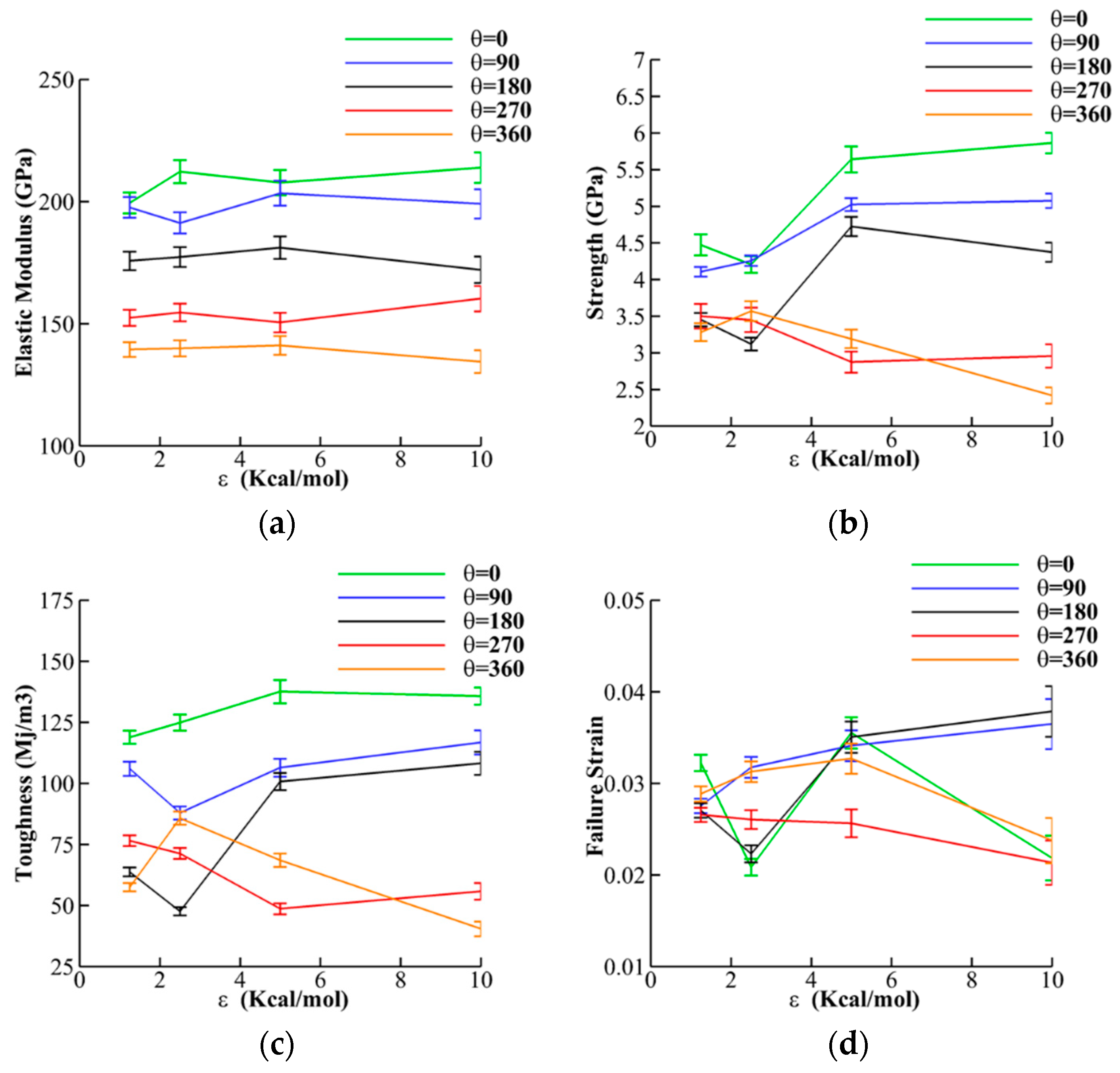
3.1. The Effect of Interface Energy and Twist

After carrying out the simulations for each case study, the elastic modulus (fitted line to 0–0.01 strain in the stress-strain curves), strength (maximum force divided by the cross-section area), toughness (area below stress-strain curve), and failure strain (strain at the maximum force) are extracted from the stress-strain curves (Figure A1). The effect of interfacial energy (ϵ) and twist (θ) on the elastic modulus of a 2 × 2 bundle (Figure 3a), shows that elastic modulus is less sensitive to the ϵ, but significantly decreases as θ increases. For instance, for θ = 360, the elastic modulus (130 ± 10 GPa) drops almost 35% from its value for θ = 0 (200 ± 10 GPa). The results for the strength of 2 × 2 bundles shows more sensitivity to both ϵ and θ. While increasing the ϵ for θ = 0, 90, and 180 increases the strength, it decreases the strength for θ = 270 and 360. For example, for θ = 0, the strength increases from 4.5 GPa at ϵ = 25 kcal/mol to 6.0 GPa at ϵ = 10.0 kcal/mol (33% increase), while for θ = 360, the strength decreases from 3.5 GPa at ϵ = 1.25 kcal/mol to 2.5 GPa at ϵ = 10.0 kcal/mol (28% decrease). In addition, the result shows that θ has more effect than ϵ on the strength and, for the same ϵ, the strength decreases by the increase of θ. The values obtained here for elastic modulus (140–200 GPa) and strength (2.5–6 GPa) are in the range of the reported experimental and MD simulation results for elastic modulus (110–200 GPa) [14,21] and the strength of 2–8 GPa [19,22], respectively. The toughness results (Figure 3c) shows a similar trend observed in the strength. Toughness is sensitive to both ϵ and θ, and for θ = 0, 90, 180, and large values of ϵ (e.g., ϵ = 5.0 and 10.0) toughness increases by the increase of ϵ. However, for θ = 270 and 360, and large values of ϵ (e.g., ϵ = 5.0 and 10.0) toughness decreases. For small values of ϵ (e.g., ϵ = 5.0 and 10.0), the results for toughness fluctuates. In addition, as θ increases from 0 to 360, toughness decreases. For example, toughness decreases from 130 ± 10 Mj/m3 for θ = 0 to 60 ± 20 Mj/m3 for θ = 360.
Figure 3d shows the results for failure strain. The results do not show a specific trend for failure strain by changing θ and ϵ, and the values are in the range of 0.03 ± 0.01 for all cases. The effect of θ and ϵ for a 5 × 5 bundle is also discussed here and compared with a 2 × 2 bundle. However, the effect of size and θ are discussed in more details in Section 3.2. Similar to 2 × 2 bundles, the effect of ϵ and θ on the elastic modulus, strength and toughness of 5 × 5 bundles (solid lines in Figure 4), shows less sensitivity to the ϵ. However, mechanical performance significantly decreases as the twist angle increases.
Comparing the results of 2 × 2 (dashed lines) and 5 × 5 (solid lines) bundles shows that increasing the size of the bundle significantly decreases the mechanical performance. For example, for θ = 0, the elastic modulus decreases by 67% from 150 ± 10 GPa for the 2 × 2 bundles to 50 ± 20 GPa for the 5 × 5 bundles. In addition, the strength decreases by 75% from 3.0 ± 0.5 GPa for the 2 × 2 bundles to 0.75 ± 0.25 GPa for the 5 × 5 bundles. The toughness also decreases on average by 50% from 60 ± 15 Mj/m3 for the 2 × 2 bundles to 30 ± 10 Mj/m3 for the 5 × 5 bundles. There is less trend in the results for failure strain, however, for most θ and ϵ the failure strain decreases by 40%.
Figure 5 demonstrates the effect of θ on the failure mechanism of 5 × 5 bundles and for ϵ = 5.0. The comparison of the broken regions for different values of θ shows that by increasing θ the crack propagates in multiple locations with a twisted shape, while for θ = 0 the crack occurs in one plane.
The reduction in mechanical performance with respect to the increase of θ can be explained by bond dissociation as a result of twist. When a bundle is twisted, the CNC particles experience tension (length increases) and reduction in stiffness and load carrying capacity due to bond dissociation. Consequently, an increase in θ decreases mechanical performance. Although increasing the ϵ in some cases compensate the reduction in strength and stiffness due to twist, for large values of ϵ, CNCs break at the lateral direction (h-bond direction) as opposed to chain direction (covalent bond), and therefore increasing ϵ cannot fully recover the strength and stiffness of the bundle.

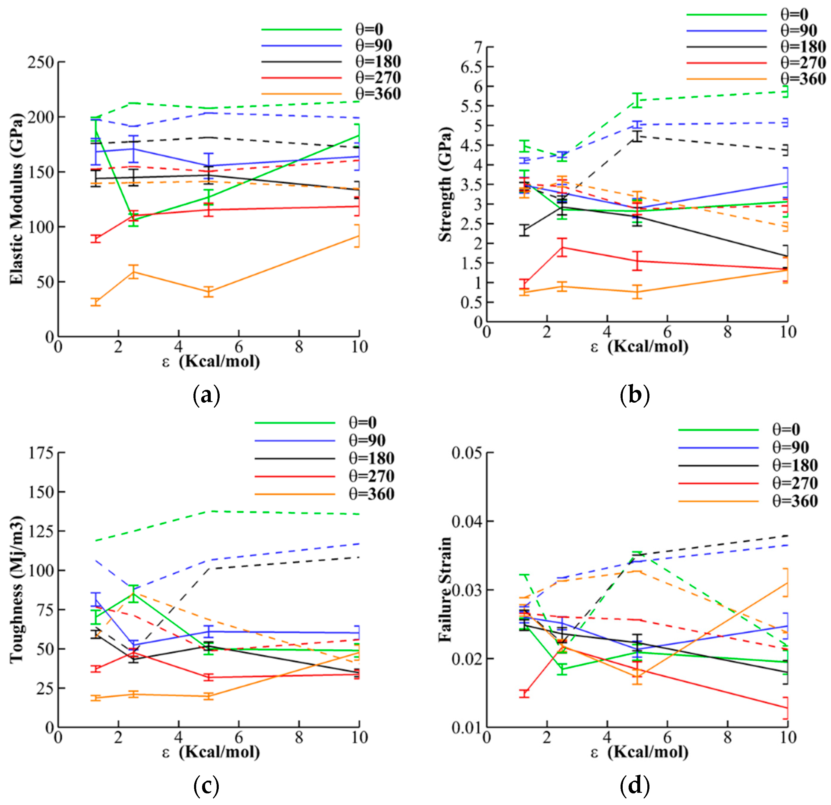
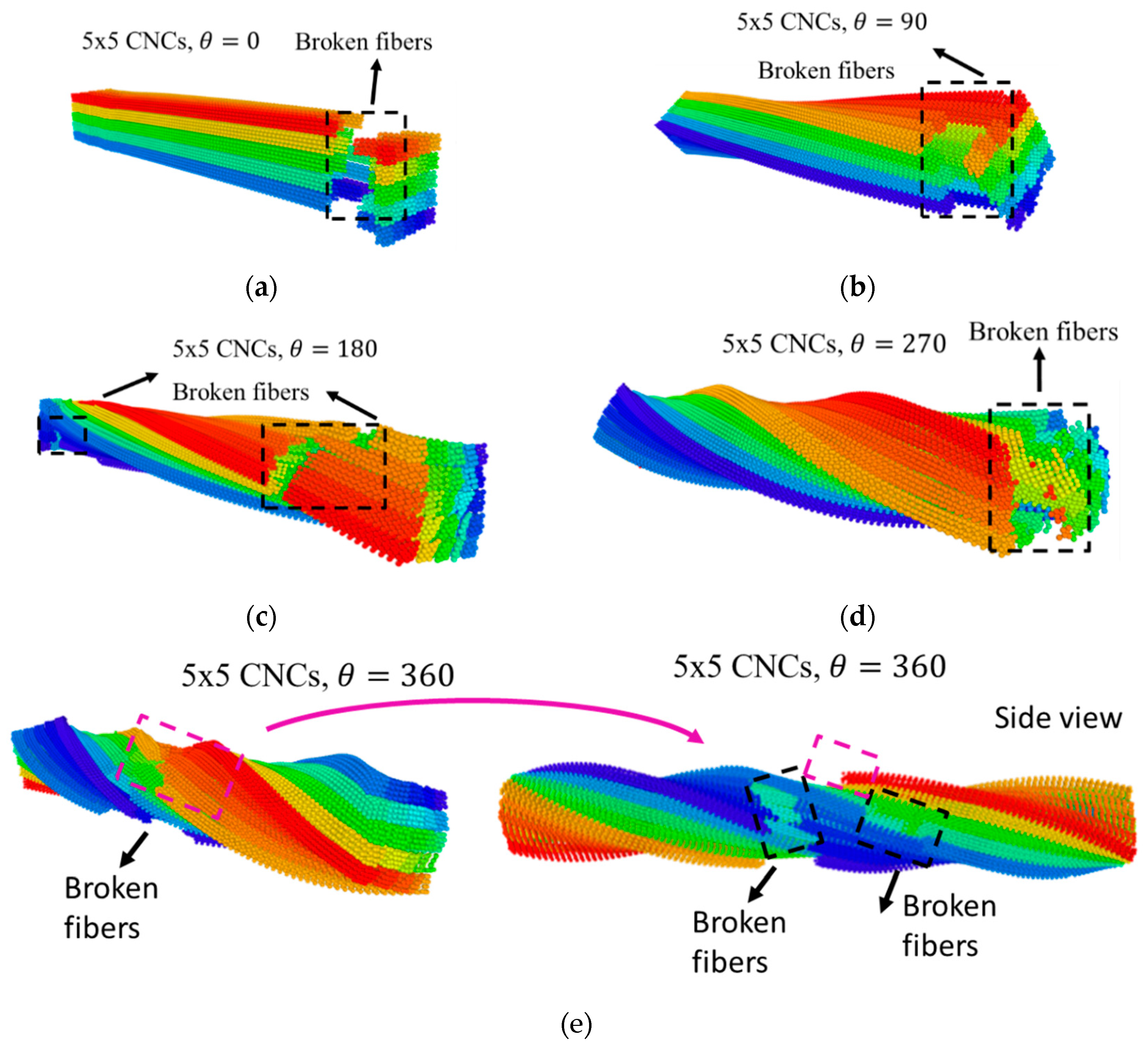
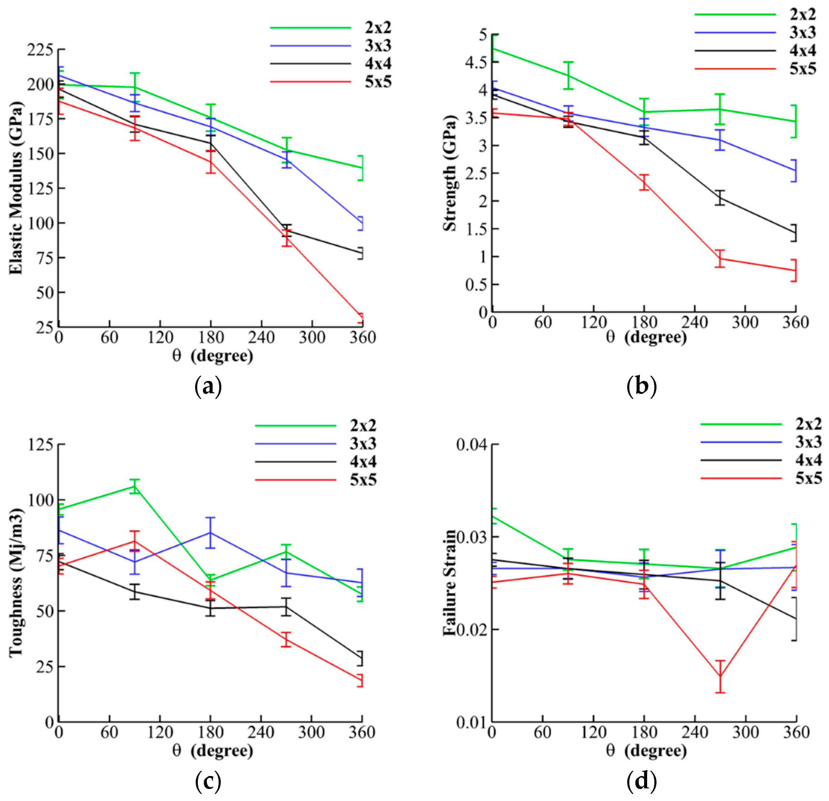
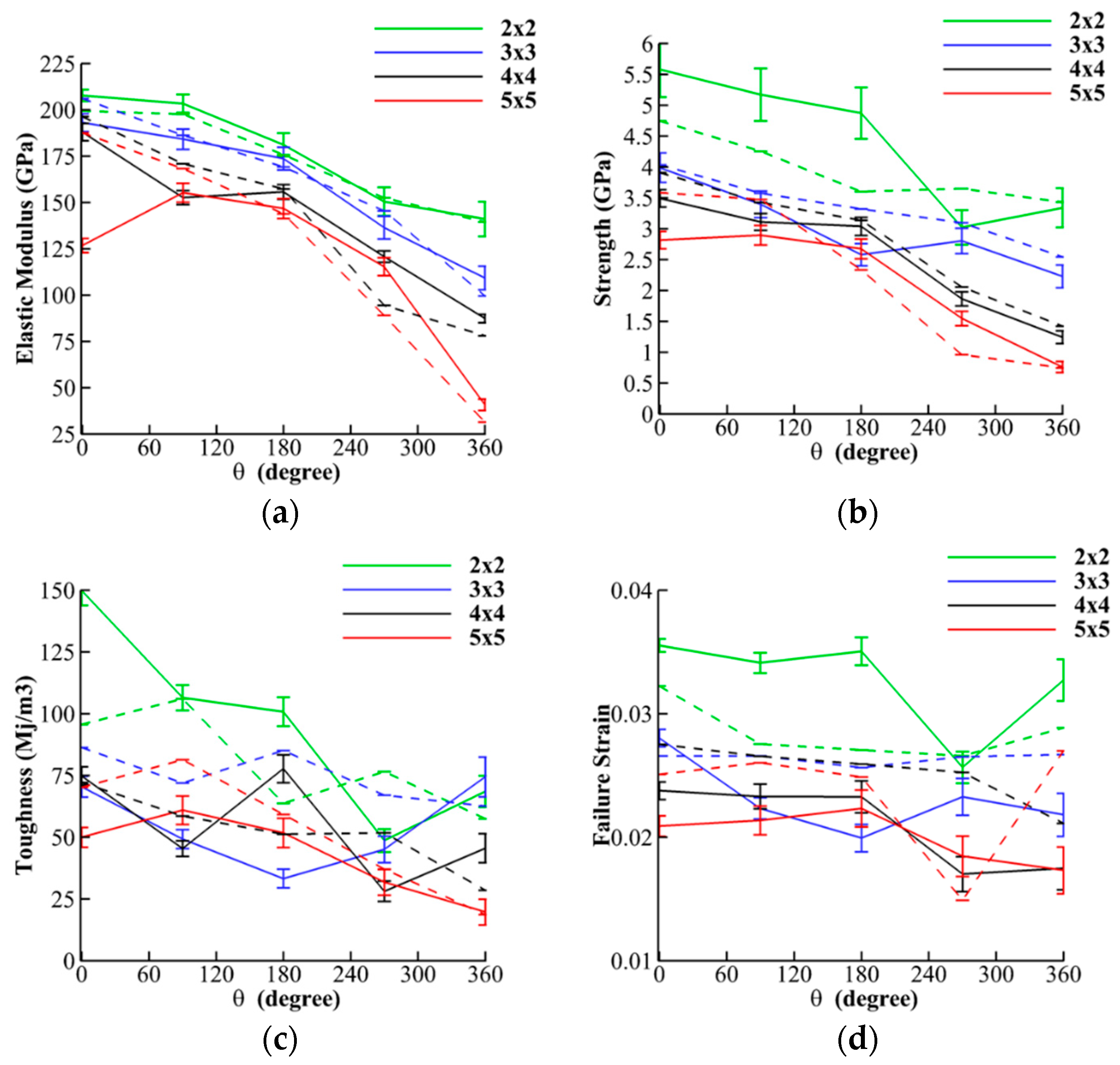
3.2. The Effect of Bundle Size and Twist

In this section, the influence of bundle size and twist on the mechanical performance of CNC bundles are evaluated. As discussed in Section 2.2, bundles with a square cross-section of 2 × 2, 3 × 3, 4 × 4, and 5 × 5 CNCs under a range of different values for ϵ and θ are examined here. Since we have examined the effect of ϵ and θ in Section 3.1. for bundles of 2 × 2 and 5 × 5, here, the effect of size and θ are evaluated for ϵ = 1.25 and 5.0 kcal/mol. The effect of size and θ on the elastic modulus for ϵ = 1.25 kcal/mol (Figure 6a), indicates that by increasing both size and θ, the elastic modulus significantly decreases, and the sensitivity of the results to the size of the bundle is more apparent as θ increases. For example, for θ = 0, the elastic modulus is 200 ± 10 GPa and 180 ± 15 GPa for 2 × 2 and 5 × 5 bundles, respectively (10% decrease); while for θ = 360, the elastic modulus is 140 ± 15 GPa and 30 ± 10 GPa, respectively (75% decrease).
The results for the strength (Figure 6b) also show sensitivity to both size and θ, and the strength decreases more rapidly for bigger bundles and larger θ. For example, for θ = 0, the strength is 4.75 ± 0.25 GPa and 3.5 ± 0.25 GPa for 2 × 2 and 5 × 5 bundles, respectively (25% decrease), while for θ = 360, the strength is 3.5 ± 0.5 GPa and 0.75 ± 0.25 GPa, respectively (75% decrease). The values obtained here for elastic modulus (175–200 GPa) and strength (3.5–5.0 GPa) for θ = 0 are in the range of the reported experimental and MD simulation results for elastic modulus (110–200 GPa) [14,21] and the strength of 2–8 GPa [19,22], respectively. However, for 4 × 4 and 5 × 5 bundles and θ > 270, the effect of size and twist leads to a decrease of elastic modulus and strength below the minimum margins for pristine CNCs (110 GPa and 2 GPa for elastic modulus and strength, respectively). Toughness is also sensitive to both size and θ (Figure 6c), and it decreases with an increase of size and θ. However, the size dependency is clearer for larger θ (θ > 180) and for θ < 180 there are regions with higher toughness for a 5 × 5 bundle than 3 × 3 and 4 × 4 bundles (for example θ = 90). For θ = 360 (large θ), toughness drops approximately 60% from 65 ± 5 (Mj/m3) for 2 × 2 bundles to 20 ± 5 (Mj/m3) for 5 × 5 bundles. The results for failure strain (Figure 6d) indicate that the failure strain varies in the range of 0.025–0.03 for a different size and θ. However, the sensitivity of failure strain to θ is higher than the sensitivity to the size.
The effect of size and θ on the mechanical performance for ϵ = 5.0 kcal/mol are also demonstrated in Figure 7 (solid lines) and compared with the results for ϵ = 1.25 kcal/mol (dashed lines in Figure 7 and solid lines in Figure 6). The results show the same trend for both ϵ = 1.25 and 5.0 kcal/mol, indicating that bundle size and θ have more influence than ϵ. By increasing ϵ from 1.25 to 5.0 kcal/mol, the most affected results are observed in the strength, toughness, and failure strain of 2 × 2 bundles, and for other bundle sizes the change is not significant (less than 20%). Figure 8a shows the effect of size and θ on the failure mechanism for ϵ = 5.0. The comparison of the broken regions for both 2 × 2 and 5 × 5 bundles shows that crack regions move from a plane crack at the boundary to a twisted crack in the middle of the bundle.
The reduction in mechanical performance with respect to the increase of size can be explained by bond dissociation as a result of twist. For a constant twisted angle, increasing the bundle size puts CNC particles under more tension (length of particles increases as a result of twist, especially for boundary particles) and there is a reduction in stiffness and load carrying capacity due to bond dissociation.

4. Summary and Conclusions

In this paper, we employed CG modeling in the framework of MD simulations to evaluate the effect of twist, interfacial energy, and size of CNC bundles on their mechanical performance. The effect of interfacial energy and twist on the mechanical performance (Section 3.1) shows that elastic modulus, strength, and toughness are more sensitive to twisted angle than interfacial energy. In addition, the effect of size of the bundle and twist on their mechanical performance (Section 3.2) revealed that both size and twist have a significant effect on the results. The comparison of the broken regions for different values of twist shows that by increasing twist angle, the crack propagates in multiple locations with a twisted shape, while for θ = 0, the crack occurs in one plane. In addition, the comparison of the broken regions for both 2 × 2 and 5 × 5 bundles shows that crack regions move from a plane crack at the boundary to a twisted crack in the middle of the bundle. The reduction in mechanical performance with respect to the increase of θ and size can be explained by bond dissociation as a result of twist (length of individual CNCs increases). When a bundle is twisted, the CNC particles experience tension (length increases) and a reduction in stiffness and load carrying capacity due to bond dissociation. For a constant twisted angle, increasing the bundle size puts CNCs under more tension and more particles experience bond dissociation, and therefore we observe a reduction in the mechanical performance of the CNC bundles by increasing twist and size. This study helps the researchers to understand the correlation between twist angle, bundle size, and the mechanical performance for optimum design of bundle size. For example, our results show that the increase of bundle size for twisted bundles dramatically decreased the strength and elastic modulus, and therefore researchers may limit the bundle size to 2 × 2 or 3 × 3. We should note that in this study we only focused on CNC-CNC surfaces and all surfaces were similarly hydrophilic. For studies involving CNC-water and CNC-polymer, the effect of hydrophilic and hydrophobic surfaces of CNC can become more important. In addition, the focus of this study was on the mechanical features rather than self-assembly and chemical aspects and we have ignored the influence of all parameters that could influence the twist angle during self-assembly, such as negative charge.

Author Contributions

Conceptualization, M.G.R. and B.G.; methodology, M.G.R.; software, B.G.; validation, B.G., and M.G.R.; formal analysis, M.G.R.; investigation, M.G.R.; resources, M.G.R.; data curation, B.G.; writing—original draft preparation, M.G.R.; writing—review and editing, M.G.R. and B.G; visualization, B.G.; supervision, M.G.R.; project administration, M.G.R.; funding acquisition, M.G.R and B.G.

Funding

This research received no external funding.

Conflicts of Interest

The authors declare no conflict of interest.

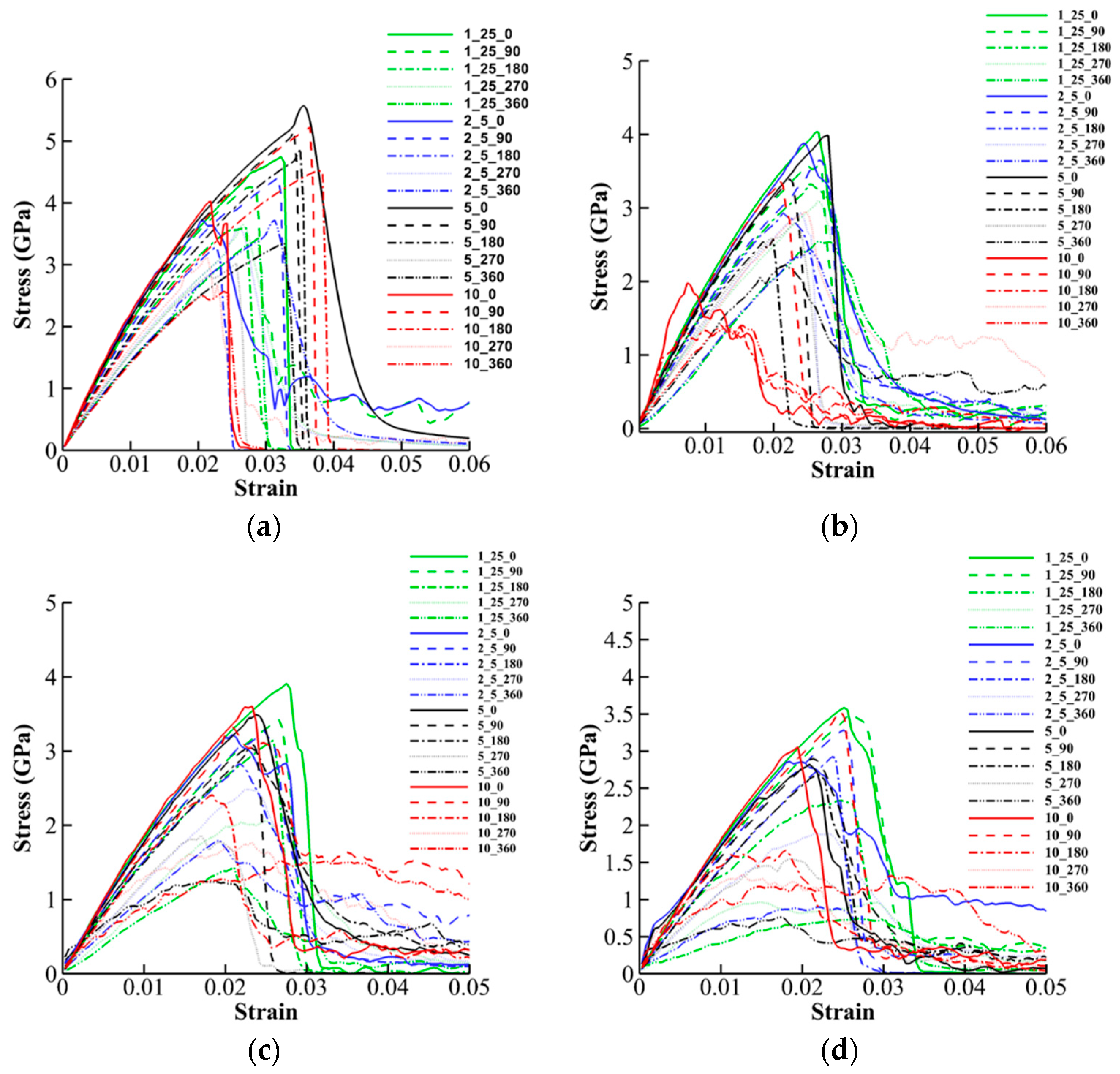
Appendix A. Stress-Strain Curves for Tensile Tests

The results shown in Section 3.1 and Section 3.2 were extracted from the stress-strain curves of the simulations. In this section, all the stress-strain curves are provided for the readers.
Figure A1. Stress-strain curves for different bundle size, interfacial energy, and twist angle. (a) 2 × 2 bundle, (b) 3 × 3 bundle, (c) 4 × 4 bundle, and (d) 5 × 5 bundle.
Jcs 03 00057 g0a1

References

  1. Moon, R.J.; Martini, A.; Nairn, J.; Simonsen, J.; Youngblood, J. Cellulose nanomaterials review: Structure, properties and nanocomposites. Chem. Soc. Rev. 2011, 40, 3941–3994. [Google Scholar] [CrossRef] [PubMed]
  2. Abdul Khalil, H.P.S.; Bhat, A.H.; Ireana Yusra, A.F. Green composites from sustainable cellulose nanofibrils: A review. Carbohydr. Polym. 2012, 87, 963–979. [Google Scholar] [CrossRef]
  3. Dufresne, A. Nanocellulose: From Nature to High Performance Tailored Materials; Walter de Gruyter GmbH & Co KG: Berlin, Germany, 2017. [Google Scholar]
  4. Dufresne, A. Nanocellulose: A new ageless bionanomaterial. Mater. Today 2013, 16, 220–227. [Google Scholar] [CrossRef]
  5. Shishehbor, M.; Zavattieri, P.D. Effects of interface properties on the mechanical properties of bio-inspired cellulose nanocrystal (CNC)-based materials. J. Mech. Phys. Solids 2019, 124, 871–896. [Google Scholar] [CrossRef]
  6. Mirzaeifar, R.; Qin, Z.; Buehler, M.J. Mesoscale mechanics of twisting carbon nanotube yarns. Nanoscale 2015, 7, 5435–5445. [Google Scholar] [CrossRef]
  7. Shishehbor, M.; Dri, F.L.; Moon, R.J.; Zavattieri, P.D. A continuum-based structural modeling approach for cellulose nanocrystals (CNCs). J. Mech. Phys. Solids 2018, 111, 308–332. [Google Scholar] [CrossRef]
  8. López, C.A.; Bellesia, G.; Redondo, A.; Langan, P.; Chundawat, S.P.S.S.; Dale, B.E.; Marrink, S.J.; Gnanakaran, S.; López, C.A.; Bellesia, G.; et al. MARTINI coarse-grained model for crystalline cellulose microfibers. J. Phys. Chem. B 2015, 119, 465–473. [Google Scholar] [CrossRef] [PubMed]
  9. Hadden, J.A.; French, A.D.; Woods, R.J. Unraveling cellulose microfibrils: A twisted tale. Biopolymers 2013, 99, 746–756. [Google Scholar] [CrossRef] [PubMed]
  10. Reising, A.B.; Moon, R.J.; Youngblood, J.P. Effect of particle alignment on mechanical properties of neat cellulose nanocrystal films. J. Sci. Technol. Prod. Process 2012, 2, 32–41. [Google Scholar]
  11. Cao, X.; Dong, H.; Li, C.M. New nanocomposite materials reinforced with flax cellulose nanocrystals in waterborne polyurethane. Biomacromolecules 2007, 8, 899–904. [Google Scholar] [CrossRef]
  12. Auad, M.L.; Mosiewicki, M.A.; Richardson, T.; Aranguren, M.I.; Marcovich, N.E. Nanocomposites made from cellulose nanocrystals and tailored segmented polyurethanes. J. Appl. Polym. Sci. 2010, 115, 1215–1225. [Google Scholar] [CrossRef]
  13. Miao, C.; Hamad, W.Y. Cellulose reinforced polymer composites and nanocomposites: A critical review. Cellulose 2013, 20, 2221–2262. [Google Scholar] [CrossRef]
  14. Wu, X.; Moon, R.J.; Martini, A. Crystalline cellulose elastic modulus predicted by atomistic models of uniform deformation and nanoscale indentation. Cellulose 2013, 20, 43–55. [Google Scholar] [CrossRef]
  15. Sinko, R.; Keten, S. Traction-separation laws and stick-slip shear phenomenon of interfaces between cellulose nanocrystals. J. Mech. Phys. Solids 2015, 78, 526–539. [Google Scholar] [CrossRef]
  16. Chen, P.; Ogawa, Y.; Nishiyama, Y.; Ismail, A.E.; Mazeau, K. Linear, non-linear and plastic bending deformation of cellulose nanocrystals. Phys. Chem. Chem. Phys. 2016, 18, 19880–19887. [Google Scholar] [CrossRef] [PubMed]
  17. Tian, K.; Shishehbor, M.; Zavattieri, P.D. Coarse Graining of Crystalline Cellulose. 2016. Available online: https://nanohub.org/resources/cgmcc. [CrossRef]
  18. Leonardo, J.; Shishehbor, M.; Zavattieri, P.D. Development of a NanoHUB Tool: Mechanical Features of Crystalline Nano Cellulose. 2017. Available online: https://nanohub.org/resources/26941.
  19. Wu, X.; Moon, R.J.; Martini, A. Tensile strength of Iβ crystalline cellulose predicted by molecular dynamics simulation. Cellulose 2014, 21, 2233–2245. [Google Scholar] [CrossRef]
  20. Wu, X.; Moon, R.; Martini, A. Calculation of single chain cellulose elasticity using fully atomistic modeling. Mol. Model. 2011, 37–43. [Google Scholar]
  21. Dri, F.L.; Hector, L.G.; Moon, R.J.; Zavattieri, P.D. Anisotropy of the elastic properties of crystalline cellulose Iβ from first principles density functional theory with Van der Waals interactions. Cellulose 2013, 20, 2703–2718. [Google Scholar] [CrossRef]
  22. Saito, T.; Kuramae, R.; Wohlert, J.; Berglund, L.A.; Isogai, A. An ultrastrong nanofibrillar biomaterial: The strength of single cellulose nanofibrils revealed via sonication-induced fragmentation. Biomacromolecules 2013, 14, 248–253. [Google Scholar] [CrossRef]
  23. Wohlert, J.; Berglund, L.A. A coarse-grained model for molecular dynamics simulations of native cellulose. J. Chem. Theory Comput. 2011, 7, 753–760. [Google Scholar] [CrossRef]
  24. Glass, D.C.; Moritsugu, K.; Cheng, X.; Smith, J.C. REACH coarse-grained simulation of a cellulose fiber. Biomacromolecules 2012, 13, 2634–2644. [Google Scholar] [CrossRef] [PubMed]
  25. Wu, S.; Zhan, H.; Wang, H.; Ju, Y. Secondary Structure Analysis of Native Cellulose by Molecular Dynamics Simulations with Coarse Grained Model. Chin. J. Chem. Phys. 2013, 25, 191. [Google Scholar] [CrossRef]
  26. Srinivas, G.; Cheng, X.; Smith, J.C. A solvent-free coarse grain model for crystalline and amorphous cellulose fibrils. J. Chem. Theory Comput. 2011, 7, 2539–2548. [Google Scholar] [CrossRef] [PubMed]
  27. Srinivas, G.; Cheng, X.; Smith, J.C. Coarse-grain model for natural cellulose fibrils in explicit water. J. Phys. Chem. B 2014, 118, 3026–3034. [Google Scholar] [CrossRef] [PubMed]
  28. Fan, B.; Maranas, J.K. Coarse-grained simulation of cellulose Iβ with application to long fibrils. Cellulose 2015, 22, 31–44. [Google Scholar] [CrossRef]
  29. Li, L.; Pérré, P.; Frank, X.; Mazeau, K. A coarse-grain force-field for xylan and its interaction with cellulose. Carbohydr. Polym. 2015, 127, 438–450. [Google Scholar] [CrossRef] [PubMed]
  30. Poma, A.B.; Chwastyk, M.; Cieplak, M. Elastic moduli of biological fibers in a coarse-grained model: Crystalline cellulose and β-amyloids. Phys. Chem. Chem. Phys. 2017, 19, 28195–28206. [Google Scholar] [CrossRef]
  31. Shishehbor, M.; Zavattieri, P.D. Evaluation of Coarse Grained Models for Cellulose NanoCrystals (CNCs). In Proceedings of the Engineering Mechanics Institute Conference (EMI), Metz, France, 25–27 October 2016. [Google Scholar]
  32. Shishehbor, M.; Pouranian, M.R.; Ramezani, M.G. Molecular investigations on the interactions of graphene, crude oil fractions and mineral aggregates at low, medium and high temperatures. Pet. Sci. Technol. 2019. [Google Scholar] [CrossRef]
  33. Shishehbor, M.; Pouranian, M.R.; Imaninasab, R. Evaluating the adhesion properties of crude oil fractions on mineral aggregates at different temperatures through reactive molecular dynamics. Pet. Sci. Technol. 2018, 36, 2084–2090. [Google Scholar] [CrossRef]
  34. Qin, X.; Feng, S.; Meng, Z.; Keten, S. Optimizing the mechanical properties of cellulose nanopaper through surface energy and critical length scale considerations. Cellulose 2017, 24, 3289–3299. [Google Scholar] [CrossRef]
  35. Leonardo, J.; Shishehbor, M.; Zavattieri, P.D. Mechanics of Crystalline Nano Cellulose Nanofilm. 2017. Available online: https://nanohub.org/resources/cnc. [CrossRef]
  36. Leonardo, J.; Shishehbor, M.; Zavattieri, P. Mechanics of CNC Nanofilm. The Summer Undergraduate Research Fellowship (SURF) Symposiu. 2017. Available online: https://docs.lib.purdue.edu/surf/2017/presentations/144.
  37. Liew, K.M.; Wong, C.H.; Tan, M.J. Twisting effects of carbon nanotube bundles subjected to axial compression and tension. J. Appl. Phys. 2006, 99, 114312. [Google Scholar] [CrossRef]
  38. Wei, X.; Naraghi, M.; Espinosa, H.D. Optimal length scales emerging from shear load transfer in natural materials: Application to carbon-based nanocomposite design. ACS Nano 2012, 6, 2333–2344. [Google Scholar] [CrossRef] [PubMed]
  39. Wang, Y.; Ostanin, I.; Gaidău, C.; Dumitrică, T. Twisting carbon nanotube ropes with the mesoscopic distinct element method: Geometry, packing, and nanomechanics. Langmuir 2015, 31, 12323–12327. [Google Scholar] [CrossRef] [PubMed]
  40. Chang, I.L. Molecular dynamics investigation of carbon nanotube resonance. Model. Simul. Mater. Sci. Eng. 2013, 21, 045011. [Google Scholar] [CrossRef]
  41. Nishiyama, Y.; Sugiyama, J.; Chanzy, H.; Langan, P. Crystal Structure and Hydrogen Bonding System in Cellulose Iα from Synchrotron X-ray and Neutron Fiber Diffraction. J. Am. Chem. Soc. 2003, 125, 14300–14306. [Google Scholar] [CrossRef]
  42. Cao, G.; Chen, X. Buckling of single-walled carbon nanotubes upon bending: Molecular dynamics simulations and finite element method. Phys. Rev. B Condens. Matter Mater. Phys. 2006, 73, 155435. [Google Scholar] [CrossRef]
  43. Plimpton, S. Fast parallel algorithms for short-range molecular dynamics. J. Comput. Phys. 1995, 117, 1–19. [Google Scholar] [CrossRef]
  44. Stukowski, A. Visualization and analysis of atomistic simulation data with OVITO—The Open Visualization Tool. Model. Simul. Mater. Sci. Eng. 2009, 18, 15012. [Google Scholar] [CrossRef]
Figure 1. (a) 3D and cross-section view of the atomistic structure of cellulose nanocrystals (CNC) [1,41]. Pink spheres denote oxygen atoms, blue spheres represent carbon atoms, and white spheres are hydrogen atoms. (b) The coarse-grained (CG) model of CNC, where each bead represents a disaccharide and is connected with 5 different internal bonds is shown with different colors. (c) A 3D and cross-section view of a 5 × 5 CNC bundle, where different particles are shown with a different color.
Jcs 03 00057 g001
Figure 2. 5 × 5 bundles of CNC with different twisted angle (θ). (a) θ = 0°, 90°, and 360°; (b) side view of a 360° rotated bundle. Tensile displacement is applied on the boundary particles of one side while the boundary particles on the other side are fixed.
Jcs 03 00057 g002
Figure 3. Mechanical performance of 2 × 2 twisted bundles of CNCs for different interfacial interactions. (a) elastic modulus, (b) strength, (c) toughness, and (d) failure strain.
Jcs 03 00057 g003
Figure 4. Mechanical performance of 5 × 5 (solid lines) and 2 × 2 (dashed lines) twisted bundle of CNCs for different interfacial interactions. (a) elastic modulus, (b) strength, (c) toughness, and (d) failure strain.
Jcs 03 00057 g004
Figure 5. Failure of 5 × 5 CNC bundles for different θ and interfacial energy of 5.0 kcal/mol. (a) θ = 0, (b) θ = 90, (c) θ = 180, (d) θ = 270, and (e) θ = 360.
Jcs 03 00057 g005
Figure 6. Mechanical performance of twisted bundle of CNCs for bundle size and ϵ = 1.25 kcal/mol. (a) elastic modulus, (b) strength, (c) toughness, and (d) failure strain.
Jcs 03 00057 g006
Figure 7. Mechanical performance of twisted bundle of CNCs for different bundle size shown for ϵ = 5.0 kcal/mol and ϵ = 1.25 kcal/mol with solid and dashed lines, respectively. (a) elastic Modulus, (b) strength, (c) toughness, and (d) failure strain.
Jcs 03 00057 g007
Figure 8. Failure mechanism for 2 × 2 and 5 × 5 bundles at θ = 0, θ = 360 and ϵ = 5.0 kcal/mol. (a) 2 × 2 bundle with θ = 0, (b) 2 × 2 bundle with θ = 360, (c) 5 × 5 bundle with θ = 0, and (d) 5 × 5 bundle with θ = 360.
Jcs 03 00057 g008

