Article

Cyclic Performance of Steel–Concrete–Steel Sandwich Beams with Rubcrete and LECA Concrete Core

1
School of Natural and Build Environments, University of South Australia, Adelaide, SA 5095, Australia
2
Structural Engineering Department, Mansoura University, Mansoura 35516, Egypt
*
Author to whom correspondence should be addressed.
J. Compos. Sci. 2019, 3(1), 5; https://doi.org/10.3390/jcs3010005
Submission received: 14 November 2018 / Revised: 17 December 2018 / Accepted: 3 January 2019 / Published: 7 January 2019
(This article belongs to the Special Issue Sustainable Rubber Composites)

Abstract

:
Due to the structural and economic features of steel–concrete–steel (SCS) structural systems compared with conventional reinforced concrete ones, they are now used for a range of structural applications. Rubcrete, in which crumbed rubber from scrap tires partially replaces mineral aggregates in concrete, can be used instead of conventional concrete. Utilizing rubber waste in concrete potentially results in a more ductile lightweight concrete that can introduce additional features to the SCS structural members. This study aimed to explore different concrete core materials in SCS beams and the appropriate shear connectors required. In this study, four SCS sandwich beams were tested experimentally under incrementally increasing flexure cyclic loading. Each beam had a length of 1000 mm, and upper and lower steel plates with 3 mm thickness sandwiched the concrete core, which had a cross-section of 150 mm × 150 mm. Two of the beams were constructed out of Rubcrete core with welded and bolted shear connectors, while the other two beams were constructed with welded shear connectors and either conventional concrete or lightweight expanded clay aggregate (LECA) concrete cores. The performance of the SCS sandwich beams including damage pattern, failure mode, load-displacement response, and energy dissipation behavior was compared. The results showed that, while Rubcrete was able to provide similar concrete cracking behavior and strength to that of conventional concrete, LECA concrete degraded the strength properties of SCS. Using bolted shear connectors instead of welded ones caused a high number of cracks that resulted in a reduced ductility and deflection capacity of the beam before failure. The rubberized concrete specimen presented an improved ductility and deflection capacity compared with its conventional concrete counterpart.

1. Introduction

The growing demand for large-size structures and high-rise buildings, especially in high-seismic risk areas, increased the need to find structural elements with high strength-to-weight ratios. This can be achieved by improving the material properties and/or by introducing new technologies or structural systems. One such technique is to sandwich a concrete core between two parallel but connected steel plates. This sandwich system is called a “steel–concrete–steel (SCS)” structural system. SCS is a special form of composite system that originated in civil engineering applications and was extended to many other applications including marine structures and nuclear power plants [1,2]. This structural system provides many structural and economical features compared to conventional reinforced concrete and steel structural systems [3,4,5,6] such as (1) higher flexural stiffness, energy absorption, impact and blast resistance, and thermal and acoustic insulation, (2) relatively lower fabrication cost and time as the components can be assembled in a modular construction fashion with less need for formwork, and (3) easy inspection and maintenance for the substrate concrete and steel plates. One form of an SCS element is an SCS beam, which takes advantage of both concrete compression performance and steel tension performance. SCS beams are different from conventional reinforced concrete beams because the standard embedded longitudinal tension and compression reinforcing steel rebars are replaced by equivalent flat external steel plates connected by shear connectors that replace conventional ligatures in reinforced concrete [7].
Some previous research was conducted on SCS sandwich beams investigating the factors affecting their structural behavior, including the concrete core thickness, the steel plate thickness, and the shape and configuration of shear connectors. However, not much research was carried out to investigate the effect of variations in the concrete core material. Liew and Sohel [8] proposed a lightweight SCS sandwich beam with 10–16-mm-diameter J-hook shear connectors and tested its flexural performance under monotonic three-point bending. Their results showed that it is necessary to provide adequate shear connectors in order to delay the formation of shear cracks in the concrete core and to ensure a ductile failure mode. The lightweight concrete (LWC) significantly decreased the beam ultimate load-carrying capacity. Sohel et al. [9] carried out static bending tests on SCS sandwich beams made out of normal weight concrete (NWC) or ultra-lightweight cement composite (ULWCC) core and various types of shear connectors, such as J-hook and headed studs. The test results showed that SCS with J-hook or headed-stud shear connectors exhibited similar load deflection behavior and ultimate strength. The ultimate strength behavior of the SCS beams with ULWCC was similar to those made out of NWC. Abdul-Razaq [10] investigated the flexural behavior of SCS sandwich beams subjected to static monotonic four-point bending load. The beams had dimensions of 150 mm × 250 mm × 1300 mm, steel plate thickness of 1.5–4.0 mm, NWC core with strength of 23.5 MPa, and 12-mm-diameter stud shear connectors with different end shapes (normal or wide) and connections to the steel plates (welded to one or both steel plates). The results showed clear separation between the concrete core and the steel plates when the studs were welded only to the bottom plate. The beam ultimate load capacity improved and the concrete/steel separation decreased when the studs were welded to both plates. The stud-end shape did not affect the beam ultimate load capacity. Huang et al. [5] tested SCS sandwich shell beams subjected to static monotonic concentrated loading. The cores were made out of ULWCC and the connectors were headed shear studs. Punching shear of the concrete core was the failure mode of tested specimens. It was also found that the punching shear resistance of the tested shells was dependent on the control perimeter of punched concrete frustum and shear connectors. El-sayed et al. [7] compared welded and bolted shear connectors with 16 mm diameter in 150 mm × 300 mm × 1600 mm SCS beam with conventional concrete core and subject to four-point bending static load. They found that using welded shear connectors resulted in higher ultimate strength and displacement by 13–15% and 6–12%, respectively, than those showed by the bolted shear connectors. Al-Gasham [11] tested the effect of shear connector diameter (10, 12, and 16 mm) and spacing (100, 200, and 250 mm) on the performance of SCS beams with 1100 mm length, 100 mm width, 150–300 mm depth. The test results showed that the stiffness of beams increased with the increase of connector diameter, while it decreased upon increasing the connector spacing. The ultimate load capacity of the SCS beams increased by 42.1% when enlarging the connector diameter by 60%. Increasing the connector spacing by 150% led to a 68.4% reduction in the ultimate load. Anandavalli et al. [12] investigated the effect of shear connector diameter (8, 10, 12, and 16 mm) on the displacement response of SCS beams with 2200 mm length, 400 mm width, and 300 mm depth. They concluded that a shear connector diameter of less than 12 mm has a negligible effect on displacement response; however, using a 16-mm-diameter shear connector showed significant increase in the beam displacement response.
The impact performance of lightweight SCS beams having J-hook connectors was studied by Liew et al. [13]. The specimens had varying parameters including different core thicknesses (80 and 100 mm) and steel plate thicknesses (4, 6, and 8 mm). Their impact test observations showed that brittle behavior and many cracks were exhibited when using LWC as the core material. On the other hand, Liew and Wang [14] reported that, in comparison with NWC and LWC, a high-strength concrete core did not improve the overall structural performance of SCS panels when subjected to blast loads. Remennikov et al. [15] demonstrated that the concrete core material and its strength had minor effects on the ultimate load carrying capacity or deformations of panels when subjected to large impact loading.
Dai and Liew [16] performed fatigue tests on SCS sandwich beams with 250 mm width, 92 mm height, and 120 mm length. The beams consisted of fiber-reinforced LWC core sandwiched in between two 6-mm face steel plates which were interlocked by J-hook shear connectors. The concrete cores used lightweight expanded clay aggregates (LECA) as coarse aggregate and lightweight expanded glass aggregates (LEGA) as fine aggregate, resulting in a concrete compressive strength of 24–28 MPa. The failure mode of the test specimens was fatigue failure of the steel concrete interface bond. Both the maximum applied stress and stress range affected the beam fatigue behavior, as reflected in the permanent deformation, hysteretic response, stiffness, and energy absorption capacity. Anandavalli et al. [17] proposed and tested SCS sandwich beams with NWC as the core material under reversed cyclic loading. In their SCS system, steel plates were connected using lacings and cross rods without any welding. The only variable in their study was the angle of the lacing. Their results showed similar behavior for all tested specimens regardless of the angle of the lacing. In addition, the laced SCS system was found to be suitable in the case of reversed cyclic loading.
From the previous literature summarized above, the behavior of SCS is highly dependent on the shear connectors. The connectors can perform adequately only if there is a strong bond with the concrete. The cyclic performance of conventional concrete or lightweight concrete SCS beams is less investigated. In addition, no previous study was carried out on utilizing Rubcrete in such beams. Rubcrete is a kind of LWC in which rubber particles partially replace concrete mineral aggregates. Recycling of used rubber in Rubcrete conserves valuable natural resources and reduces the amount of tire rubber entering landfill [18]. Experimental studies on Rubcrete materials showed that using rubber in concrete enhances its ductility, toughness, impact resistance, energy dissipation, and damping ratio [19,20,21]. However, it reduces its compressive strength, tensile strength, and modulus of elasticity compared to conventional concrete [22]. The dynamic characteristics of Rubcrete concrete make it a potential candidate for concrete members subjected to dynamic loading conditions [23,24,25]. Duarte et al. [26] concluded that Rubcrete increased the ductility of concrete-filled steel tubes, which is a major benefit for structures in seismic areas where energy dissipation is needed.
This paper presents the first experimental work on the behavior of SCS sandwich beams having Rubcrete as their core with different types of shear connectors, to investigate the cracking behavior under incrementally increasing flexure cyclic loading. The cyclic performance of Rubcrete SCS sandwich beams was compared with conventional and LECA SCS beams. Combining Rubcrete with the SCS sandwich structural system may produce a new composite structure with adequate strength, ductility, and resistance to earthquake excitation. The data in this research provide introductory information necessary to support the further development of SCS structural systems utilizing rubber waste.

2. Experimental Program

In this research, the performance of SCS sandwich beams having different types of concrete core material and different types of shear connector was experimentally investigated. The effects of using different core material (conventional concrete, Rubcrete, and LECA concrete), and using welded or bolted shear connectors were examined by testing four different beams under incrementally increasing flexure cyclic loading. Figure 1 shows the details of the beam geometry and shear connectors. Each beam specimen was 1000 mm long (900 mm clear span) and had a concrete cross section of 150 mm × 150 mm sandwiched between two 3-mm-thick steel plates at each side. Welded or bolted shear connector studs of 10 mm diameter were used with a spacing of 75 mm in the short direction and 100 mm in the long direction (see Figure 1). Table 1 summarizes the different components of all beams tested in this study. The specimen code used in this test matrix has two parts. The first part uses the letters “CC”, “Rub”, or “LECA” standing for conventional concrete, Rubcrete, or LECA concrete, respectively. The second part uses the letter “W” or “B” standing for welded or bolted shear connectors, respectively.

2.1. Materials

General-purpose cement type, in accordance with Australian Standard (AS) 3972 [27], was used as the binder material in the concrete mixes. Dolomite stone with nominal maximum size of 14 mm was used as coarse aggregate. River sand with a maximum aggregate size of 5 mm was used as fine aggregate. Both coarse rubber and LECA used in this study had particle sizes of 9.5–16.0 mm and were used as a partial replacement of concrete stone by volume (Table 1). The sieve analyses for all aggregates used are shown in Figure 2. The measured specific gravity, fineness modulus, and unit weight were 2.72, 7.93, and 1570 kg/m3, respectively, for dolomite; 2.65, 2.36, and 1630 kg/m3, respectively, for sand; 0.97, 7.52, and 530 kg/m3, respectively, for rubber; and 1.00, 8.05, and 400 kg/m3, respectively, for LECA. Polycarboxylic ether type superplasticizer (SP) with a specific gravity of 1.085 was added to the concrete mixes to control the concrete workability.
Steel plates with 300 MPa yield strength, 416 MPa ultimate strength, and 200 GPa modulus of elasticity were used in the SCS sandwich beams. Deformed steel rebar was used as the welded shear connectors and threaded steel rod was used as the bolted shear connectors. Both welded and bolted shear connectors had 300 MPa yield strength, 430 MPa ultimate strength, and 200 GPa modulus of elasticity. M10 hexagonal steel nuts class 4.6 were used to connect the threaded rod to the steel plates.

2.2. Concrete Mix Design

The concrete mixes were designed according to AS 1012.2 [28] with target compressive strengths of 40 MPa. Constant water-to-cement (W/C) ratio of 0.5, SP of 0.6% (by cement weight), and cement content of 400 kg/m3 were used in all mixes of this study. The fine/coarse aggregate ratio was 1.0/1.2 by weight. The mixing procedure for all mixes was as follows: mix dry sand, stone, rubber (if any), and LECA (if any) for 1 min; add half of the water and mix for 1 min; rest for 2 min; add cement, remaining water, and admixtures, and then mix for 2 min. Due to the high water absorption of LECA particles, they were soaked in tap water for 24 h before the mixing day and then were left in air to dry the particle surface only [29].

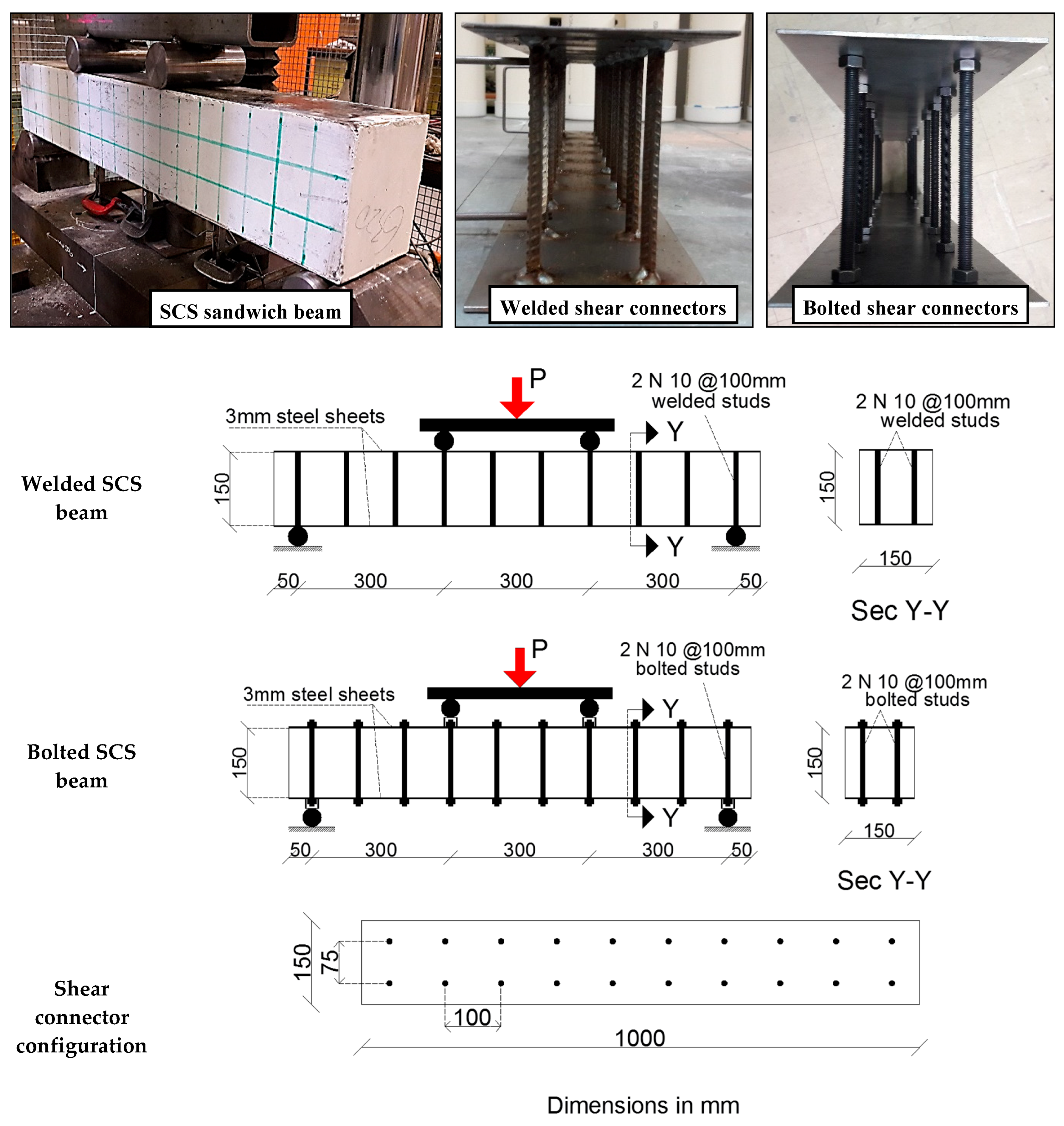
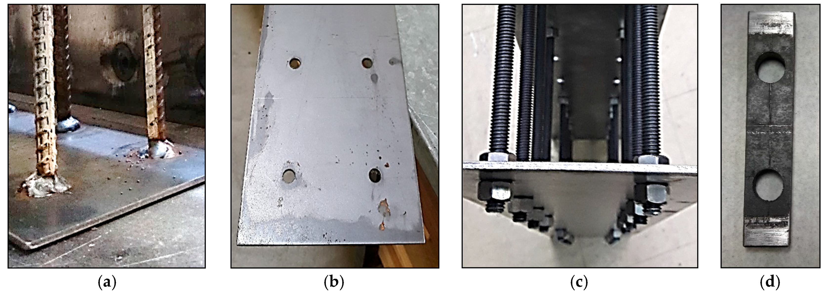
2.3. Variables and Specimen Preparation

The variables in this research were rubber/LECA content (0% and 20% as a replacement of stone volume) and shear connector type (welded and bolted). The concrete stone was partially replaced by rubber/LECA in order to achieve a lightweight concrete core for the tested beam. The welded shear connectors were first placed in the designed locations followed by arc-welding all the way around the connecting point (see Figure 3a). In the bolted shear connectors, the steel plates were first punched at the designed locations; then, the threaded rods were bolted to the steel plate using a pair of M10 hexagonal steel nuts (see Figure 3b,c). The SCS sandwich beams were cast in wooden formwork and the pouring direction was perpendicular to the shear connectors’ longitudinal axes and parallel to the beam width. No surface pre-treatment was used between the steel plates and concrete. Concrete compaction was carried out using a mechanical vibrator. Three standard 100 × 200 mm cylinders were taken from each mix to measure the 28-day compressive strength. All beams and cylinders were de-molded after 24 h, labeled, and then cured in a water bath at 23 ± 2 °C, according to AS 1012.8.1 [30]. The beam specimens were then painted white and marked with grids for ease of crack observations as shown in Figure 1.

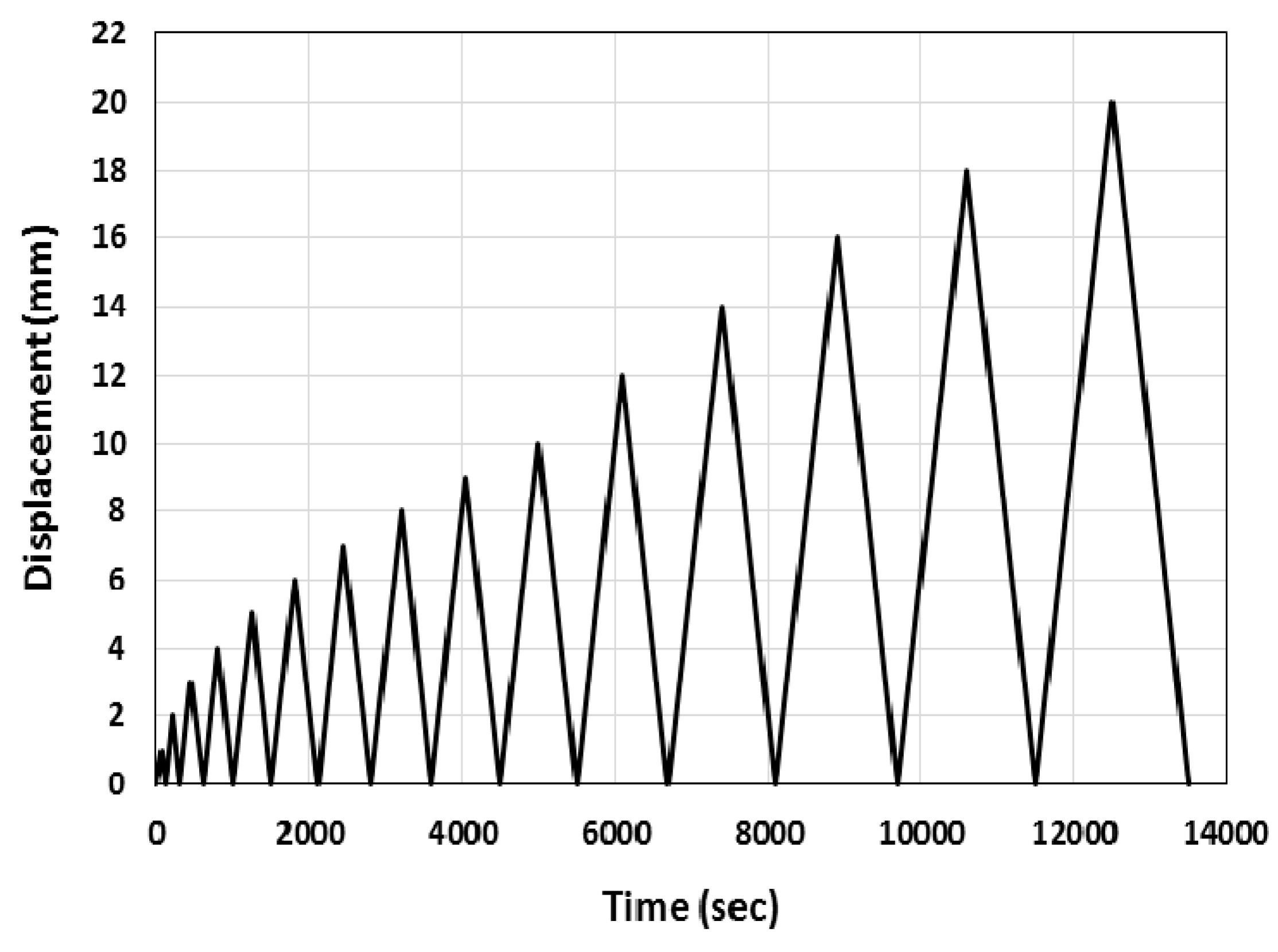
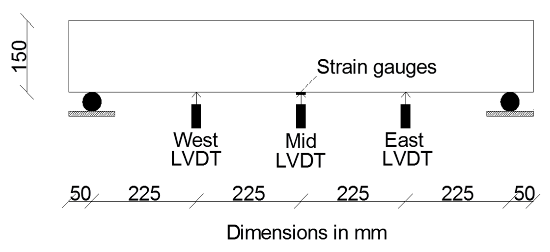
2.4. Instrumentation and Test Set-Ups

Cyclic loading was applied in displacement control mode using an 1800-kN-capacity testing machine. All beam specimens were subjected to cyclic loading at a constant rate of 0.02 mm/s with 1-mm-displacement increment up to 10 mm applied displacement, followed by 2-mm-displacement increment up to 20 mm applied displacement. The specimens were then subjected to monotonic loading at a rate of 0.02 mm/s until failure. Each displacement level consisted of one cycle. Figure 4 shows the cyclic loading pattern used in this experimental study. As some of the bolted shear connectors in beam Rub-B were located at the same place as the beam supports and loading points, small rigid steel prisms (30 mm width × 150 mm length × 15 mm thickness with two 20-mm-diameter holes at 75 mm apart; see Figure 3d) were placed at these support/loading points of the test specimen to avoid any stress concentrations. Figure 5 shows the arrangement of linear variable differential transformers (LVDTs) and strain gauges for the tested beams. All beams were instrumented with three LVDTs to measure the beam deflection at different locations. One was located at the beam mid-span (450 mm from beam supports) and the other two were located at 225 mm from the beam supports (west and east LVDTs in Figure 5). As the expected failure of the steel plate was at the tension zone, two electrical strain gauges were placed at the beam mid-span on the bottom steel plate in the longitudinal direction to measure its strains while loading. The strain gauges had a gauge length of 10 mm and gauge resistance of 120 ± 0.3 Ω. Loading of the test specimens and measurement recording were controlled using a data acquisition system and LABVIEW 8.6 software [31].

3. Experimental Results and Discussion

The effects of using different concrete core materials and using welded or bolted shear connectors on the performance of the SCS sandwich beams, including damage pattern, failure mode, load-displacement response, and energy dissipation behavior, were studied in this experimental investigation. Table 2 shows the cyclic test results of the tested beams. In this table, the ultimate displacement is defined as the displacement when the load capacity of a test specimen dropped by 20% from its peak load capacity.

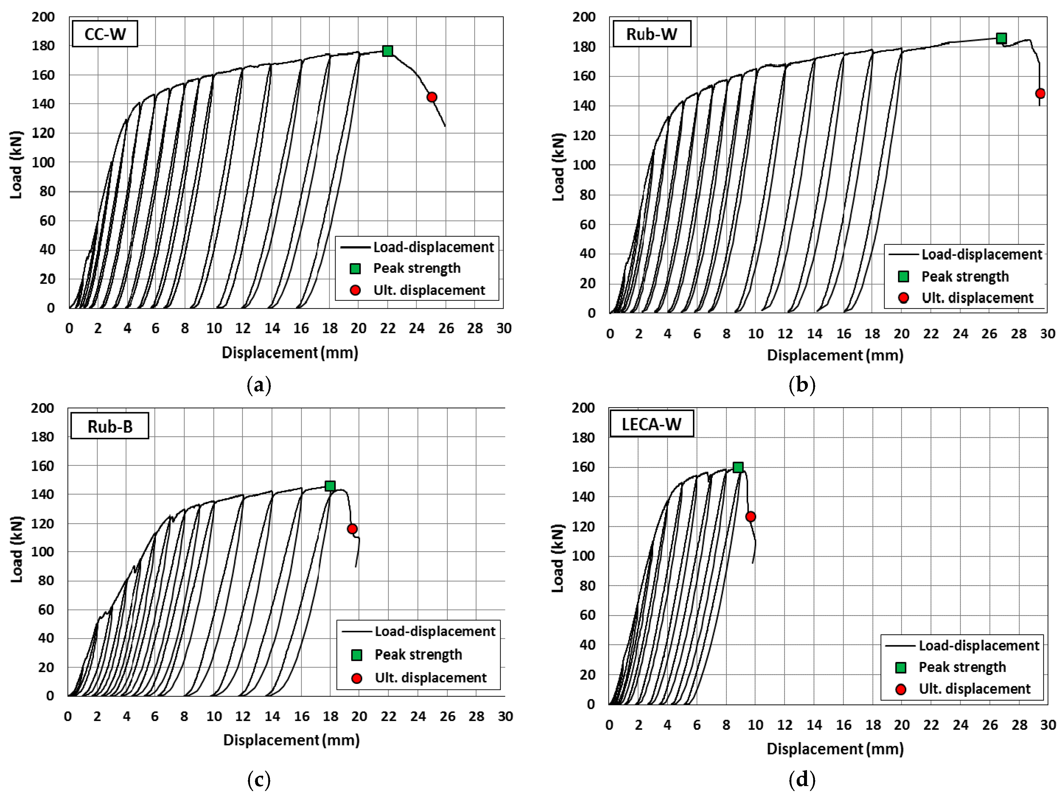
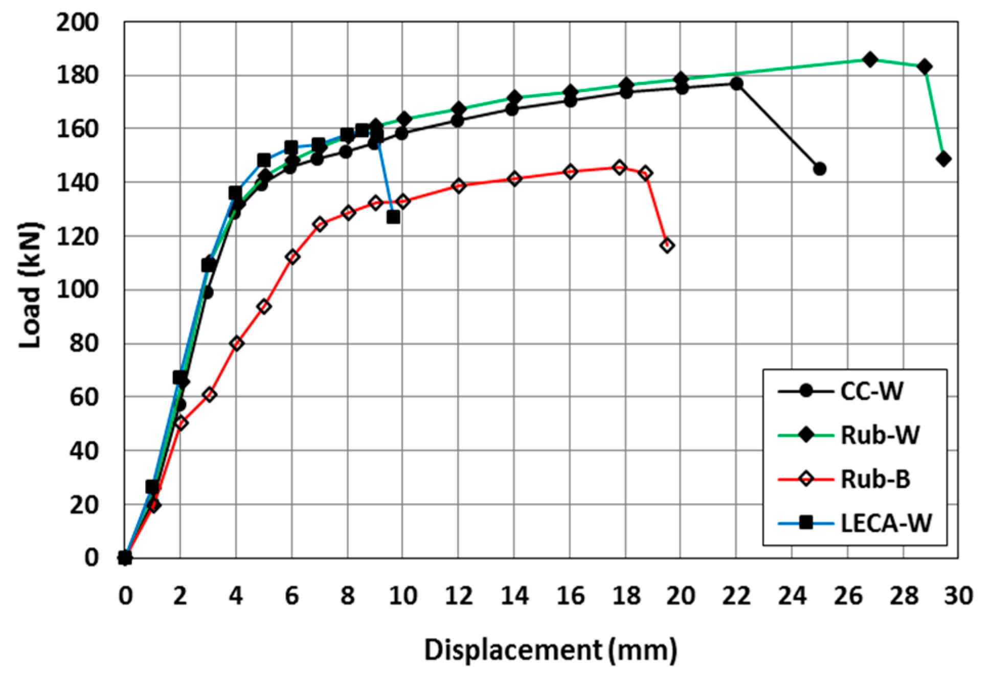
3.1. General Behavior and Backbone Curves
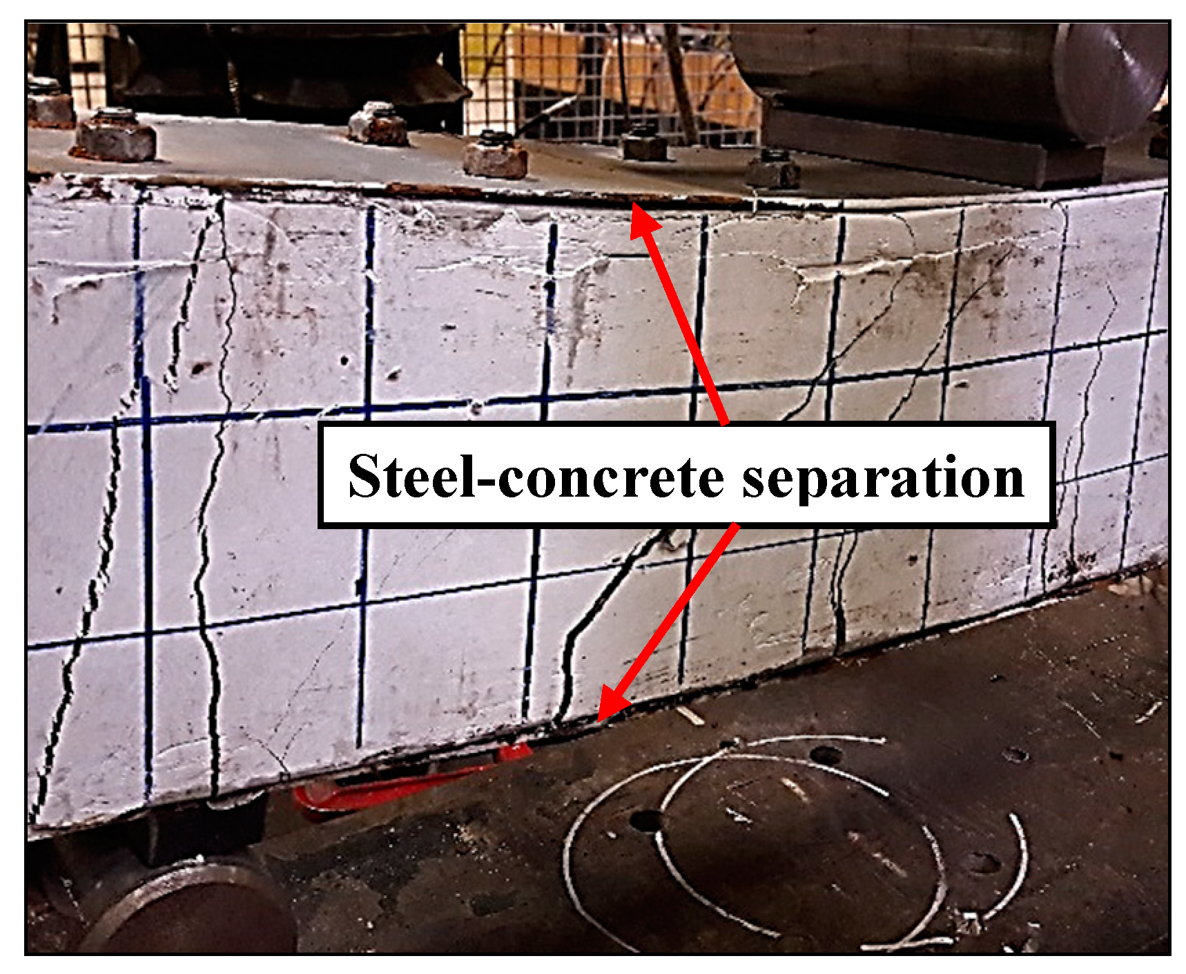
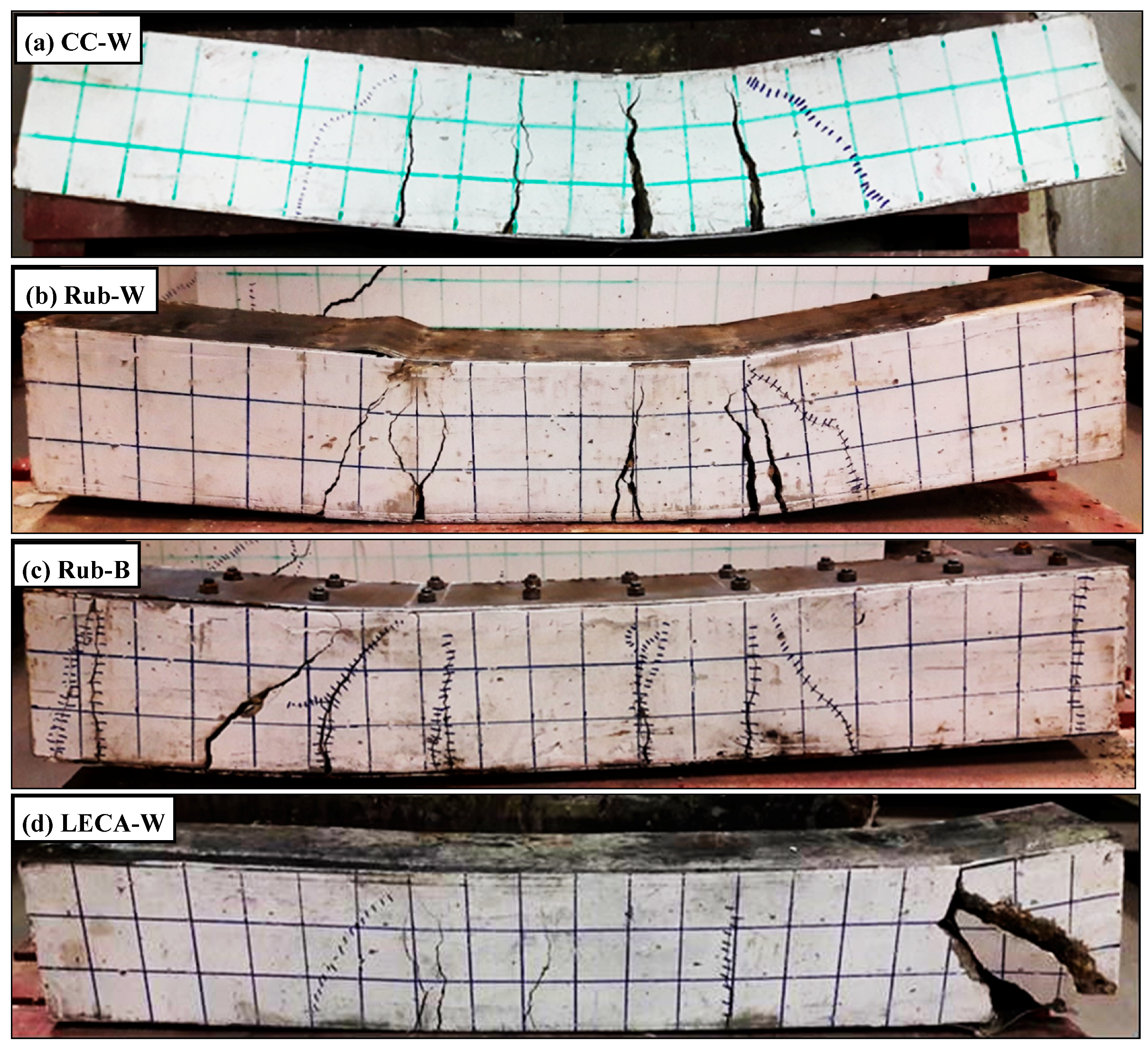
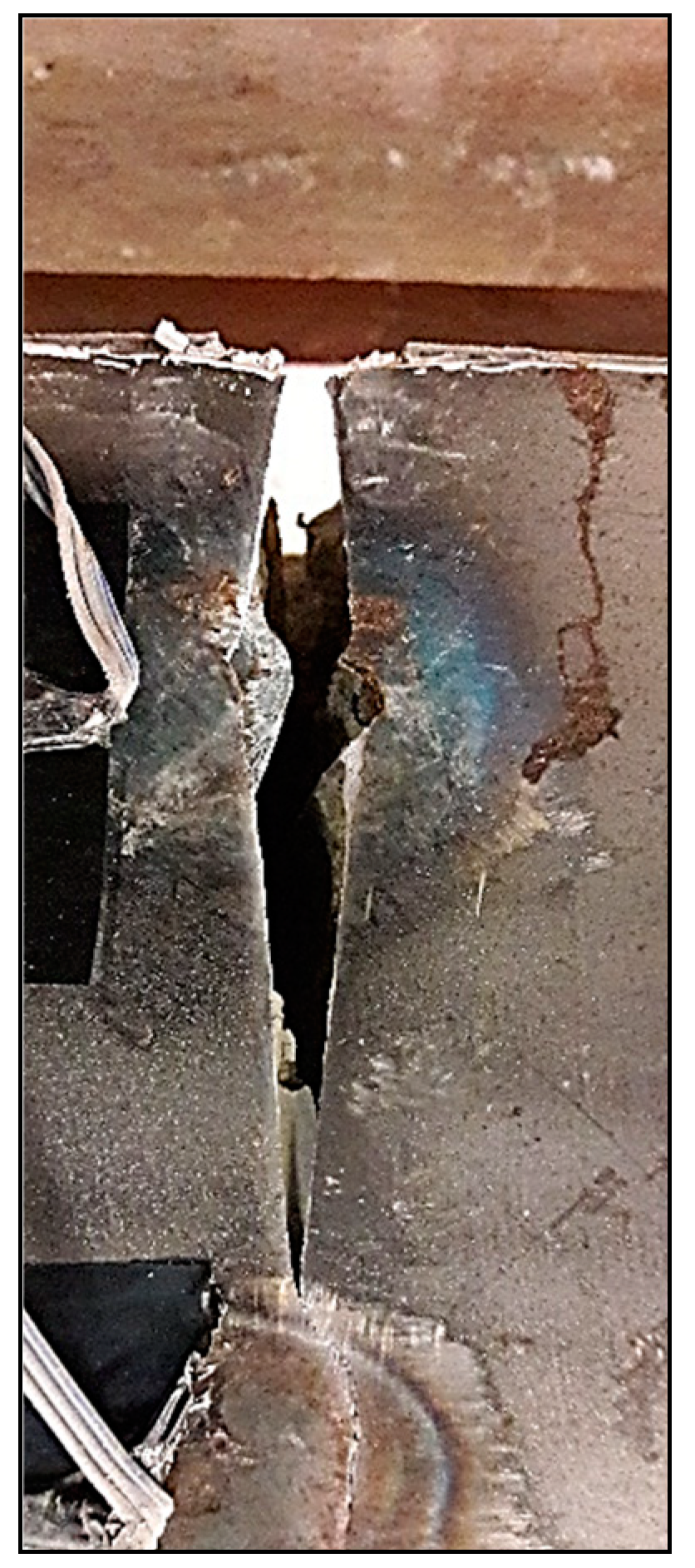
The recorded load versus beam mid-span displacement for each beam is shown in Figure 6. All specimens showed stable nonlinear hysteretic loops until the end of the test. The nonlinearity was attributed to the concrete cracking, steel plate yielding, and/or concrete spalling. The load increased with the applied displacement increase until the beam stiffness decreased due to rupture of the bottom steel plate at 20 mm displacement in the CC-W specimen, crippling of the top steel plate at 27 mm displacement in the Rub-W specimen, steel-concrete separation at 20 mm displacement in the Rub-B specimen, and concrete shear cracking at 10 mm displacement in the LECA-W specimen. Defining specimen failure as a 20% drop in the load resistance, the CC-W, Rub-W, Rub-B, and LECA-W specimens failed at 25.1 mm, 29.4 mm, 19.5 mm, and 9.5 mm displacements, respectively.
The backbone curves of the tested specimens obtained as the envelope of all cycles during the cyclic loading are shown in Figure 7. As shown in the figure, after reaching peak loading capacity of 176.7 kN, 186.1 kN, 145.7 kN, and 159.3 kN, for specimens CC-W, Rub-W, Rub-B, and LECA-W, respectively, the strength degraded due to steel plate yielding, crack width increase, crack extension, and/or concrete spalling. In the case of welded shear connectors, using different concrete core materials showed similar general behavior. Each backbone curve had bilinear relationships with approximately similar slopes (stiffnesses) connected by a transition zone. However, the deformation capacity of the specimens varied significantly due to the effect of the coarse aggregate used. The beam specimen Rub-B with bolted shear connectors behaved similarly to the corresponding welded shear connector specimen. However, due to the formation of multiple early cracks, it showed less stiffness and, hence, less loading resistance and ultimate displacement capacity.
The flexural toughness (T) of the tested specimens was determined as the area under the backbone curve of each specimen shown in Figure 7 and plotted in Figure 8. The flexural toughness was mainly affected by the beam loading capacity and deformability level. Replacing 20% of concrete stone by coarse rubber increased T by 26%; however, using LECA in concrete decreased T by 69%. This indicated higher deformability for the concrete including rubber compared with that including LECA, due to the low toughness and high brittleness of the LECA particles. Using bolted shear connectors instead of welded ones decreased the T by 52%.
Figure 9 shows the peak load and ultimate displacement of the tested beams. Both the peak load and ultimate displacement of Rub-W (SCS sandwich beam utilizing Rubcrete with welded shear connectors) were higher than those of the conventional concrete counterpart, CC-W, by 5% and 17%, respectively, and higher than those of the LECA concrete specimen, LECA-W, by 17% and 309%, respectively. This indicated that adding rubber to concrete can enhance the displacement ductility (as explained in Section 3.4) and, hence, the structural performance under seismic loads. Although the Rubcrete in this study had relatively lower axial compressive strength than the other concrete classes (Table 2), it was still able to enhance the flexural behavior of the SCS sandwich beam since the Rub-W specimen showed peak strength and ultimate displacement 5.3% and 17.1% higher than those of CC-W specimen, respectively. This was due to the partial confinement of the concrete core provided by the top and bottom steel plates. Previous research showed that Rubcrete is able to show better efficiency than conventional concrete under confinement conditions [24,32,33]. In addition, it was shown by other researchers that using Rubcrete (with lower compressive strength than conventional concrete) in structures subjected to flexural loading showed insignificant decrease in the flexural strength [20,21,24].
The LECA-W specimen showed a lower loading capacity and ultimate displacement capacity by 9.8% and 62.1%, respectively, compared to those of the CC-W specimen. This was due to the relatively lower deformability of LECA-W as LECA particles are crushable, which results in immature beam cracking and, hence, reduced flexural resistance. Comparing the bolted shear connectors used in specimen Rub-B with the welded shear connectors used in specimen Rub-W, the bolted specimen showed lower strength and ultimate displacement by 21.7% and 33.6%, respectively. The connection point between the bolted shear connectors and either the top or bottom steel plates is considered as a partially fixed connection compared to that of the welded shear connectors which is a fully fixed connection. The partially fixed connection could allow for some rotation during the beam loading which adds more stress to the concrete core. Due to this partial fixity, the concrete confinement was not as much as that in Rub-W specimen. In addition, this partially fixed connection resulted in slippage between the steel and concrete and easy separation (see Figure 10). Moreover, the drilled holes in the steel plates at the shear connector locations decrease the cross-section area of the steel plate resisting the tension and compression stresses. For all of these reasons, Rub-B specimens experienced early cracking and, hence, lower strength and ductility.

3.2. Failure Mode

Figure 11 shows the global damage, crack extension, and concrete spalling, if any, of the tested beam specimens. Clear concrete spalling was only observed in the LECA-W specimen where the concrete spalling started at a cycle of 7 mm displacement at about 50–100 mm from the bottom-east direction and then developed to 150 mm toward the east direction and 100 mm toward the beam top at the 9 mm displacement cycle. The crack initiation and propagation had different patterns in the tested specimens. All cracks initiated at the bottom of the specimen and extended 100–150 mm toward the beam top. In the CC-W specimen, many vertical cracks occurred symmetrically at 50 mm, 150 mm, and 250 mm from the specimen’s vertical centerline at mid-span displacements of 6 mm and 9 mm (see Figure 11a). The CC-W specimen failure occurred at 20 mm mid-span displacement when the bottom steel plate suddenly ruptured (see Figure 12) at 50 mm from the specimen’s vertical centerline, which was the same location as the first crack in the specimen, initiated at 6 mm displacement. In specimen Rub-W, vertical and inclined cracks occurred at 50 mm, 175 mm, and 250 mm right of the specimen’s vertical centerline, and at 150 mm and 225 mm left of the specimen’s vertical centerline at mid-span displacements of 4 mm and 6 mm (see Figure 11b). Rub-W specimen failure occurred at 27 mm displacement due to steel crippling in the top steel plate, located at 200 mm left of the specimen’s vertical centerline. The Rub-B specimen showed the highest number of vertical and inclined cracks that occurred at 3 mm, 6 mm, 8 mm, and 20 mm mid-span displacements and were located at 50 mm, 150 mm, 250 mm, and 450 mm right of the specimen’s vertical centerline, and at 125 mm, 225 mm, 325 mm, and 450 mm left of the specimen’s vertical centerline (see Figure 11c). Rub-B specimen failure occurred at 20 mm mid-span displacement due to steel–concrete separation at both top and bottom steel plates, located at 300–400 mm left of the specimen’s vertical centerline. In the LECA-W specimen, vertical cracks occurred at 3 mm, 7 mm, and 8 mm mid-span displacement, located 150 mm right of the specimen’s vertical centerline, and at 50 mm, 150 mm, and 250 mm left of the specimen’s vertical centerline (see Figure 11d). Due to the relatively lower deformation capacity and shear strength of LECA particles, at 10 mm mid-span displacement, specimen LECA-B failed with a significant shear crack in the concrete core that was extended from above the right support of the beam toward 150 mm from the beam top right end.
Comparing the global damage of the tested specimen utilizing different concrete materials and welded shear connectors, it can be concluded that the Rubcrete is able to provide similar concrete cracking behavior to that of conventional concrete with no rupture in the steel plates, which could be a lifesaving feature under cyclic loading events. This is attributed to the low modulus of elasticity and high Poisson’s ratio of concrete containing rubber, which results in a relatively ductile concrete with lower crushing compared to conventional concrete, even though the core concrete compressive strength was reduced due to the use of rubber particles instead of course aggregate. However, the LECA concrete could have immature sudden failure under stress due to the crushability and brittle failure of the LECA particles that control the crack development [29]. Using bolted shear connectors instead of welded ones in Rubcrete specimens caused a higher number of and wider cracks, which resulted in a reduced deformation capacity. More experimental investigations are recommended for this structural system using Rubcrete with additional design details to control the local buckling and rupture of the top and bottom steel plate. Steel plate thickness, and shear connector diameter, spacing, and shape are mainly suggested for future testing.

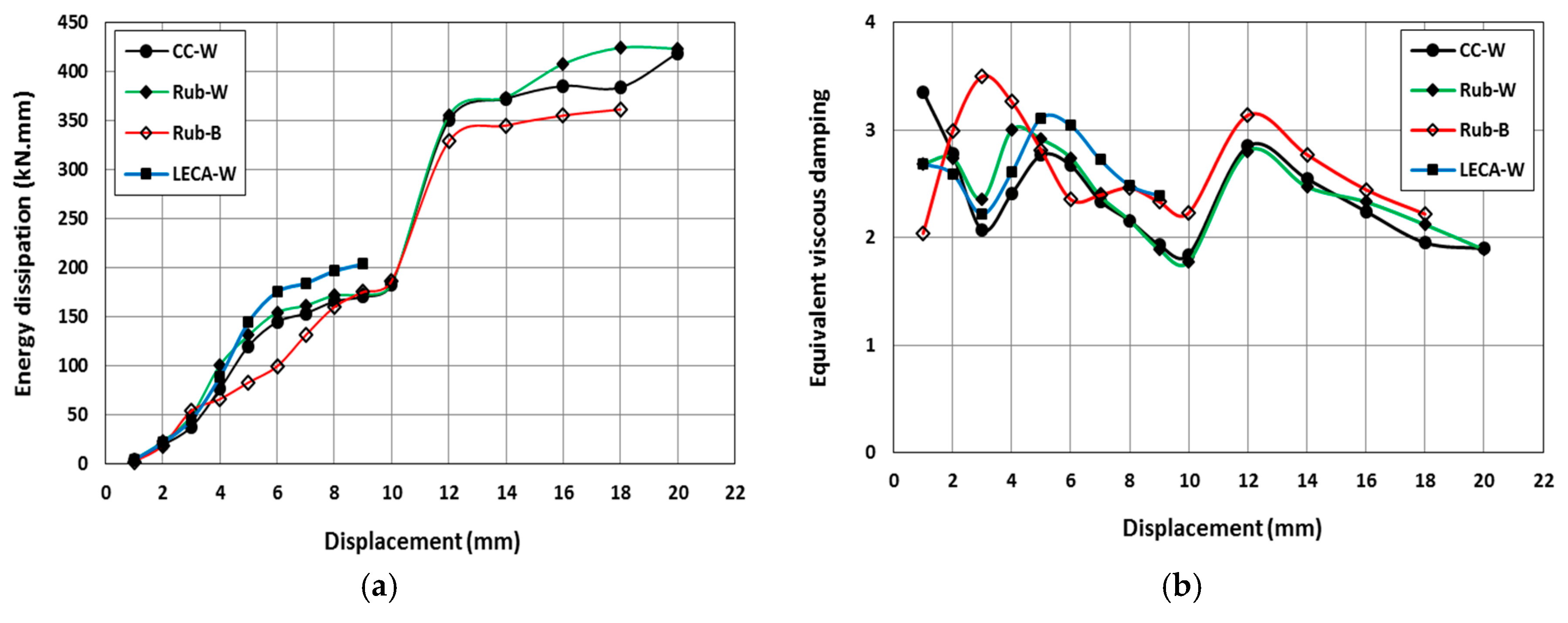
3.3. Energy Dissipation and Equivalent Viscous Damping

The energy dissipation of the tested beams at each displacement was calculated from the hysteretic curves as the enclosed area by cycle of the load versus displacement curve. Figure 13a shows the amount of energy dissipated at each loading cycle for the tested specimens. As shown in the figure, the energy dissipation increased with the displacement increase in all tested specimens. For specimens with welded shear connectors (CC-W, Rub-W, and LECA-W), the energy dissipation increased almost linearly with the displacement increase up to a displacement of 6 mm. Beyond that and up to 10 mm displacement, the increasing rate of the energy dissipation decreased. This was because the initiation and propagation of most of the concrete core cracks occurred up to 6 mm displacement and was then followed by a lesser level of dissipation between 6 mm and 10 mm displacement, basically due to the opening and closing of the cracks. A significant increase in the energy dissipation was observed when the displacement increased from 10 mm to 12 mm (excluding the LECA-W specimen as it failed before 10 mm displacement) due to doubling the displacement increment; then, the energy dissipation increased until the end of cyclic loading with the same rate as that observed between 6 mm and 10 mm displacement. Specimen Rub-B that had bolted shear connectors showed a similar energy dissipation trend to that of Rub-W, but different increasing rates due to the development of the number of cracks initiated at 3–8 mm mid-span displacement.
Rubcrete was able to increase the energy dissipation of the SCS sandwich beam by an average of 10% throughout the cyclic loading compared to a conventional concrete SCS beam. The same superiority of Rubcrete energy dissipation (of 10% higher) was observed when comparing it with that of LECA concrete up to 5 mm displacement. However, beyond 5 mm displacement until the LECA concrete specimen failure (at 9 mm displacement), it showed higher energy dissipation than the Rubcrete by an average of 14%. This might be attributed to the crushability of LECA particles that developed while concrete cracks were opening and closing which did not occur in rubber particles. The specimen with welded shear connectors (Rub-W) showed higher energy dissipation than the specimen with bolted connectors (Rub-B) by an average of 24% throughout the cyclic loading. This might be attributed to the partially fixed connections between the shear connectors and steel plates that caused steel plate slipping over concrete and, hence, less contribution to dissipating energy.
The equivalent viscous damping coefficient (ζeq) was calculated using Equation (1) [34] and plotted in Figure 13b for all tested specimens.
ζ e q = 1 4 π   E d E s ,
where Ed is the energy dissipated in each loading cycle and Es is the stored energy measured at the peak force of the same cycle.
As shown in Figure 13b, the variation of ζeq of the tested specimens with displacement showed similar behavior with the ζeq value ranging between 1.8 and 3.5. Both CC-W and Rub-W specimens displayed almost the same values of ζeq throughout the cyclic test due to the similarity of their backbone and energy dissipation curves. Using LECA aggregate in LECA-W specimens showed higher ζeq than those shown by CC-W and Rub-W specimens by an average of 6% due to its relatively higher energy dissipation before its early failure. Bolted shear connectors showed higher ζeq by an average of 9% than the welded ones. This was due to the significant decrease of Es (which increases ζeq) compared with the less significant decrease of Ed (which decreases ζeq).

3.4. Ductility

The displacement ductility values, μ, of the specimens were calculated using the following equation [35]:
μ = Δ u Δ y ,
where the Δ y and Δ u values were obtained using the bilinear approximation of the capacity developed following the procedure provided by Federal Emergency Management Agency (FEMA) 356 [36]. The ultimate displacement, Δ u , is the displacement at the peak load, Vy and Δ y . are the effective yield load and displacement, and Ke and αKe are the effective yield and post-yield stiffness, respectively. An iterative procedure was used to determine the bilinear idealized curves assuming the equal energy concept and intersection of the two curves at 0.6 Vy.
Table 3 presents the characteristics of the bi-linearized capacity curves and the ductility of the test specimens obtained using Equation (2). As shown in the table, the LECA-W specimen had the lowest ductility of 2.3, which can be attributed to the premature failure of this specimen as explained before. While the ductility of the conventional concrete specimen CC-W was 4.9, it increased to 6.5 when rubber was added to the mix in specimen Rub-W. This can be attributed to the effect of rubber particles in bridging the cracks, and limiting the propagation and the width of the cracks. While using similar concrete materials in Rub-W and Rub-B, the shear bolted connectors resulted in significant loss in ductility. This can be attributed to the reduced stiffness of the specimen, as shown in Table 3.

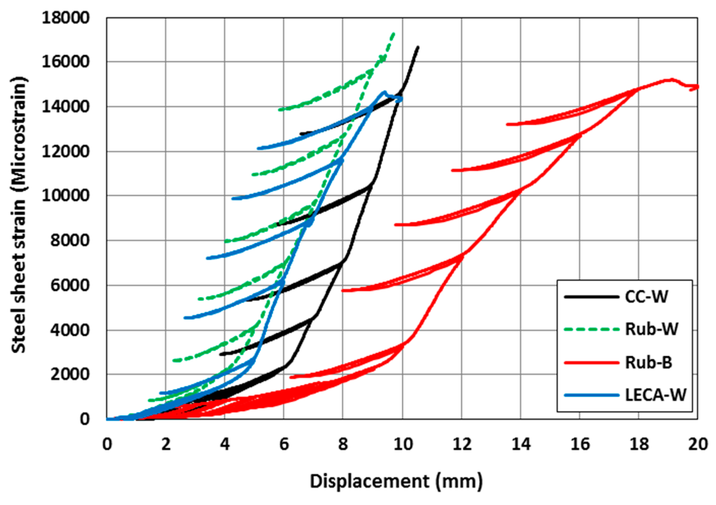
3.5. Bottom Steel Plate Strains

Longitudinal strains in the bottom steel plate were measured at the mid-span of each beam. Figure 14 shows the variation of plate strains with the cyclic displacement. All strain gauges malfunctioned at about 16,000 microstrain; however, the recorded strains before this limit could be compared. As shown in the figure, the strains in the steel plates increased with the displacement increase at a relatively slow rate before the specimen yielding and at a higher rate after yielding. Before yielding, there was no significant difference in the measured strains for all tested specimens. After yielding and at a given displacement, specimens Rub-W and LECA-W showed significantly higher strains than those shown by the CC-W specimen. This was due to the earlier crack initiation and propagation in those specimens (at 3–4 mm displacement) that caused higher stresses and strains. At the displacement range of 6–10 mm, Rub-W and LECA-W showed steel plate strains higher than those of CC-W by an average of 90%. Using rubber compared with using LECA resulted in higher steel plate strains by an average of 20%. This indicated that using Rubcrete increases the structure strains, which could be attributed to the higher dilation of the rubberized concrete compared to the LECA concrete. The bolted shear connector specimen (Rub-B) showed the lowest measured strain in the bottom steel plate throughout the test, although it utilized Rubcrete. This might be attributed to the drilled holes in the steel plates that may have resulted in strain concentrations around the holes’ sections rather than the location of the mounted strain gauges and, hence, lower recorded strains. More experimental investigations are recommended with a greater number of strain gauges that could help in deriving better conclusions.

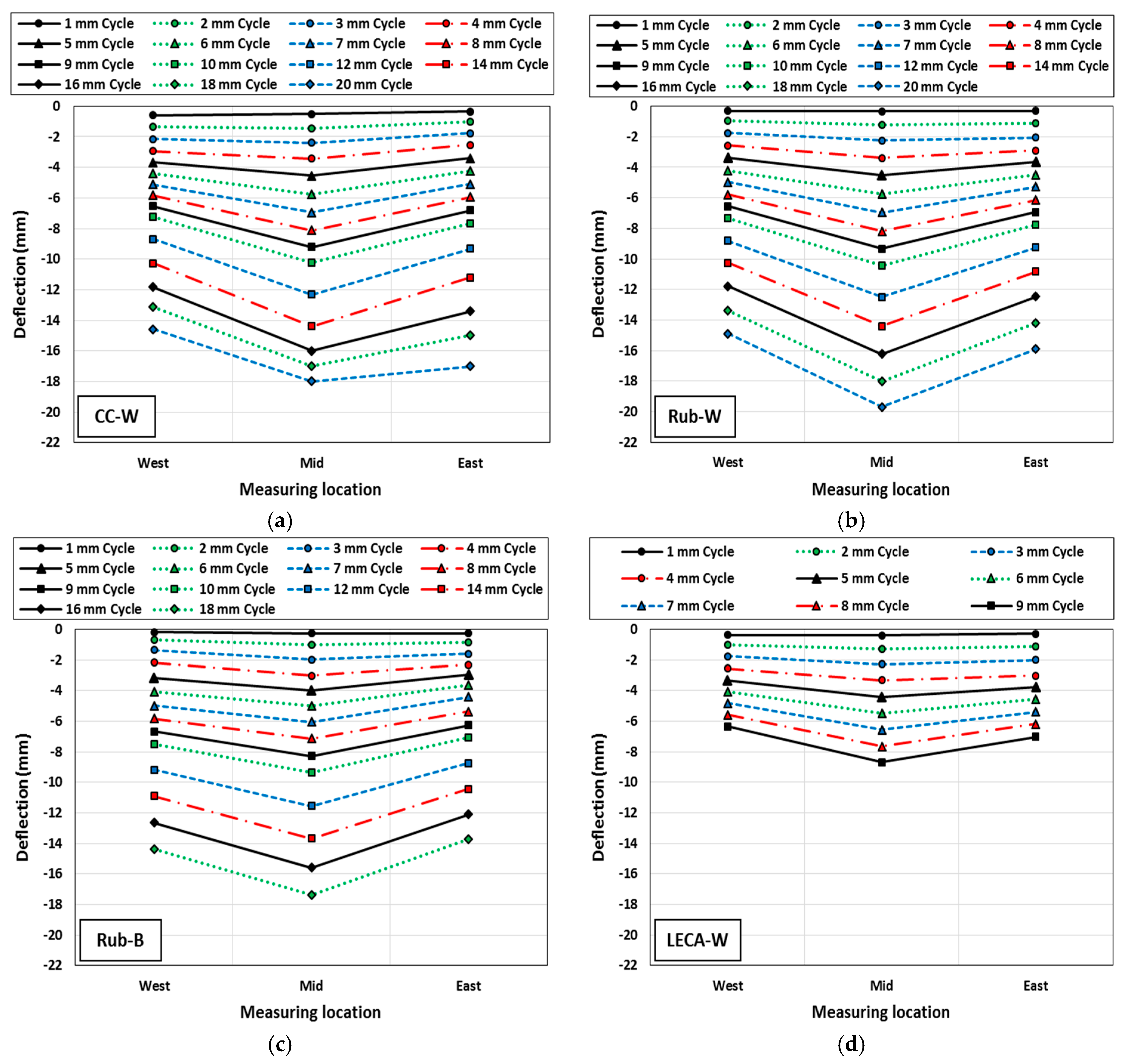
3.6. SCS Beam Deflection Pattern

The beam deflection was measured using LVDTs at three different locations, namely west, mid, and east (see Figure 5). Figure 15 shows the distribution of the maximum measured deflections at different locations for each loading cycle. As shown in the figure, increasing the displacement increased the beam deflections with almost symmetrical deflection distribution along the beam span up to a displacement level of 9 mm. Beyond that, due to the non-symmetric nature of the crack widths under loading, some differences were recorded between the measured east and west deflections, as shown clearly in specimen CC-W (Figure 15a). Specimen Rub-W showed similar deflections to those shown by the CC-W specimen up to 14 mm displacement. However, due to the relatively higher deformability of Rubcrete, it displayed 6% higher deflection between 14 mm and 20 mm displacement. Specimen LECA-W showed lower deflection than those of CC-W and Rub-W by 7% and 5%, respectively, due to the low deformability and brittleness of LECA particles compared to mineral stone or rubber. Specimen Rub-B showed lower deflection than that shown by Rub-W by an average of 11%. This was attributed to sliding occurring at the steel–concrete interface of this specimen that allows for lateral movement of the concrete core while cracking, which resulted in less vertical movement (deflection).

4. Conclusions

This paper presents the first experimental work on the behavior of SCS sandwich beams made out of Rubcrete, with different shear connectors, under incrementally increasing cyclic loading. The cyclic performance of SCS sandwich beams made out of Rubcrete was compared with SCS sandwich beams made out of conventional or LECA concrete. The results of this investigation are summarized in the following points:
  • Rubcrete was able to provide similar concrete cracking behavior to that of conventional concrete with no rupture of the steel plates, which could be a lifesaving feature under earthquake loading events. However, LECA concrete showed earlier sudden failure. Using bolted shear connectors instead of welded ones in Rubcrete specimens caused a higher number of cracks that were able to decrease the specimen deformability before failure.
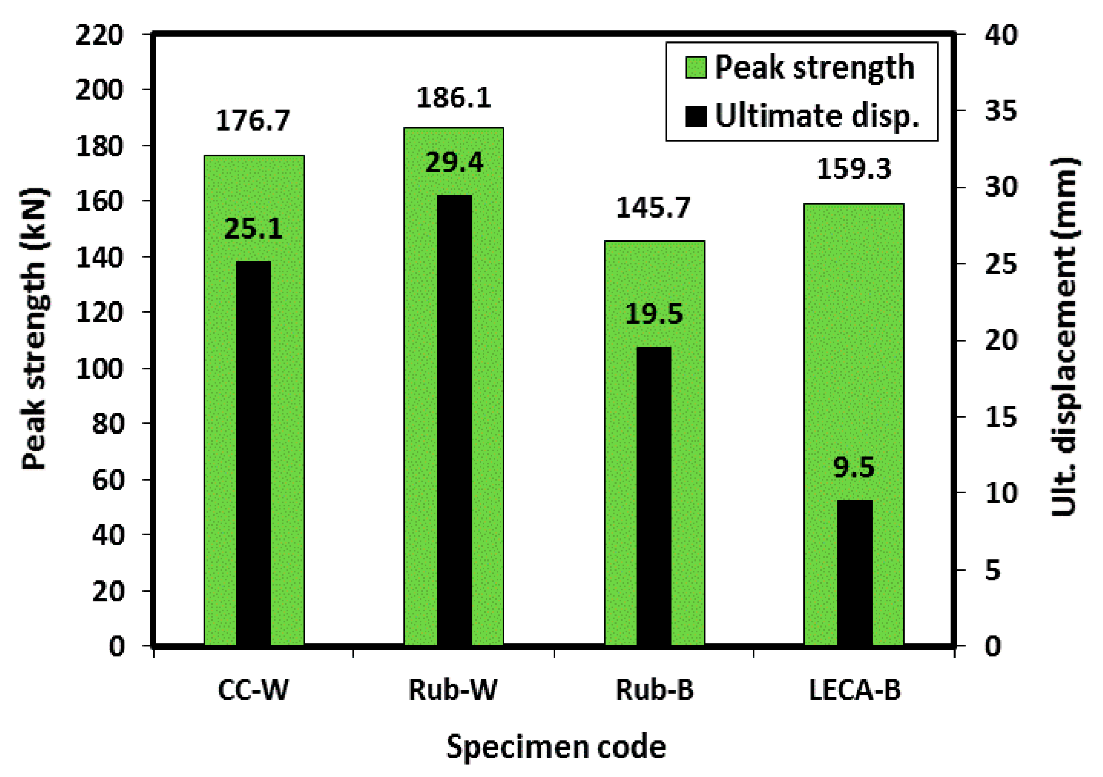
  • The peak strength and ultimate displacement of the Rub-W specimen were higher than those of the CC-W specimen by 5% and 17%, respectively, and higher than those of the LECA-W specimen by 17% and 309%, respectively. The LECA-W specimen showed less strength and ultimate displacement by 9.8% and 62.1%, respectively, compared to those of the CC-W specimen. The Rub-B specimen showed lower strength and ultimate displacement by 21.7% and 33.6%, respectively, compared to those of Rub-W specimen.
  • Rubcrete was able to increase the energy dissipation of the SCS sandwich beam by an average of 10% compared to that of conventional concrete. The same superiority of Rubcrete energy dissipation was observed when comparing it with that of LECA concrete up to 5 mm displacement. However, beyond 5 mm displacement until the LECA concrete specimen failure, it showed higher energy dissipation than that of Rubcrete by an average of 14%.
  • The LECA-W specimen had the lowest ductility of 2.3 due to its premature failure. While the ductility of the conventional concrete specimen CC-W was 4.9, it increased to 6.5 when rubber was added to the mix in specimen Rub-W. Using bolted connectors instead of welded reduced the ductility significantly.
  • Specimens Rub-W and LECA-W showed 90% higher steel plate strains than those shown by CC-W specimens. The Rub-W specimen showed 20% higher steel plate strains than the LECA-W specimen.

Author Contributions

Conceptualization, O.Y. and R.H.; methodology, O.Y.; formal analysis, O.Y.; investigation, O.Y. and R.H.; resources, J.E.M.; writing—original draft preparation, O.Y., R.H. and J.E.M.; writing—review and editing, Y.Z. and X.M.; supervision, O.Y.; project administration, J.E.M.

Funding

This research received no external funding.

Acknowledgments

The authors gratefully acknowledge the donation of the rubber aggregate by Tyrecycle Pty. Ltd. (Somerton, Australia). The authors also acknowledge the contributions of Tom Benn, Tim Golding, and Renyu Qiu who assisted in the experimental work reported in this paper.

Conflicts of Interest

The authors declare no conflict of interest.

References

  1. Leekitwattana, M.; Boyd, S.W.; Shenoi, R.A. An alternative design of steel-concrete-steel sandwich beam. In Proceedings of the 9th International Conference on Sandwich Structures (ICSS-9), Pasadena, CA, USA, 14–16 June 2010. [Google Scholar]
  2. Chu, M.; Song, X.; Ge, H. Structural performance of steel-concrete-steel sandwich composite beams with channel steel connectors. In Proceedings of the 22nd International Conference on Structural Mechanics in Reactor Technology (SMiRT 22), San Francisco, CA, USA, 18–23 August 2013. [Google Scholar]
  3. Huang, Z.; Liew, J.Y.R. Steel-concrete-steel sandwich composite structures subjected to extreme loads. Int. J. Steel Struct. 2016, 16, 1009–1028. [Google Scholar] [CrossRef]
  4. Liew, J.Y.R.; Sohel, K.M.A. Structural performance of steel-concrete-steel sandwich composite structures. Adv. Struct. Eng. 2010, 13, 453–470. [Google Scholar] [CrossRef]
  5. Huang, Z.-Y.; Wang, J.-Y.; Richard Liew, J.Y.; William Marshall, P. Lightweight steel–concrete–steel sandwich composite shell subject to punching shear. Ocean Eng. 2015, 102, 146–161. [Google Scholar] [CrossRef]
  6. Varma, A.H.; Malushte, S.R.; Lai, Z. Modularity & innovation using steel-plate composite (sc) walls for nuclear and commercial construction. In Proceedings of the 11th International Conference on Advances in Steel and Concrete Composite Structures, Beijing, China, 3–5 December 2015. [Google Scholar]
  7. El-sayed, K.M.; Khalil, N.N.; El Backlesh, T.A. Flexural behavior of steel–concrete–steel sandwich slabs. Adv. Res. 2016, 8, 1–13. [Google Scholar] [CrossRef]
  8. Liew, J.Y.R.; Sohel, K.M.A. Lightweight steel–concrete–steel sandwich system with j-hook connectors. Eng. Struct. 2009, 31, 1166–1178. [Google Scholar] [CrossRef]
  9. Sohel, K.M.A.; Richard Liew, J.Y.; Yan, J.B.; Zhang, M.H.; Chia, K.S. Behavior of steel–concrete–steel sandwich structures with lightweight cement composite and novel shear connectors. Compos. Struct. 2012, 94, 3500–3509. [Google Scholar] [CrossRef]
  10. Abdul-Razaq, A. Experimental and analytical study of the steel-concrete-steel beam under flexural behavior. In Proceedings of the 5th Jordanian International Civil Engineering Conference, Amman, Jordan, 13–15 December 2011. [Google Scholar]
  11. Al-Gasham, T.S.S. Experimental behavior of steel-concrete-steel sandwich beams with truss configuration of shear connectors. J. Eng. 2016, 22, 18–29. [Google Scholar]
  12. Anandavalli, N.; Rajasankar, J.; Prakash, A.; Sivaprasad, B. Static response of steel-concrete-steel sandwich beam with bi-directionally inclined connectors. Am. J. Civ. Eng. Arch. 2013, 1, 15–20. [Google Scholar] [CrossRef]
  13. Liew, J.Y.R.; Sohel, K.M.A.; Koh, C.G. Impact tests on steel–concrete–steel sandwich beams with lightweight concrete core. Eng. Struct. 2009, 31, 2045–2059. [Google Scholar] [CrossRef]
  14. Liew, J.Y.R.; Wang, T.Y. Novel steel-concrete-steel sandwich composite plates subject to impact and blast load. Adv. Struct. Eng. 2011, 14, 673–687. [Google Scholar] [CrossRef]
  15. Remennikov, A.M.; Kong, S.Y.; Uy, B. The response of axially restrained non-composite steel–concrete–steel sandwich panels due to large impact loading. Eng. Struct. 2013, 49, 806–818. [Google Scholar] [CrossRef] [Green Version]
  16. Dai, X.X.; Richard Liew, J.Y. Fatigue performance of lightweight steel–concrete–steel sandwich systems. J. Constr. Steel Rese. 2010, 66, 256–276. [Google Scholar] [CrossRef]
  17. Anandavalli, N.; Lakshmanan, N.; Rajasankar, J.; Knight, G.S. Behaviour of steel–concrete–steel sandwich composite beams with lacing subjected to reversed cyclic loads. J. Sandw. Struct. Mater. 2017, 1–21. [Google Scholar] [CrossRef]
  18. Li, G.; Garrick, G.; Eggers, J.; Abadie, C.; Stubblefield, M.A.; Pang, S.S. Waste tire fiber modified concrete. Compos. Part B Eng. 2004, 35, 305–312. [Google Scholar] [CrossRef]
  19. Al-Tayeb, M.M.; Abu Bakar, B.H.; Ismail, H.; Akil, H.M. Effect of partial replacement of sand by recycled fine crumb rubber on the performance of hybrid rubberized-normal concrete under impact load: Experiment and simulation. J. Clean. Prod. 2013, 59, 284–289. [Google Scholar] [CrossRef]
  20. Hassanli, R.; Youssf, O.; Mills, J.E. Experimental investigations of reinforced rubberized concrete structural members. J. Build. Eng. 2017, 10, 149–165. [Google Scholar] [CrossRef]
  21. Youssf, O.; ElGawady, M.A.; Mills, J.E. Experimental Investigation of Crumb Rubber Concrete Columns under Seismic Loading; Elsevier: Amsterdam, The Netherlands, 2015; pp. 13–27. [Google Scholar]
  22. Gupta, T.; Chaudhary, S.; Sharma, R.K. Assessment of mechanical and durability properties of concrete containing waste rubber tire as fine aggregate. Constr. Build. Mater. 2014, 73, 562–574. [Google Scholar] [CrossRef]
  23. Resende, F.M.; Roitman, N.; Magluta, C.; Toledo Filho, R.D. Influence of Scrap Rubber Tires and Steel Fibers on the Damping Characteristics of Normal Concrete; Civil Engineering Deparment, COPPE/Federal University of Rio de Janero: Rio de Janero, Brazil, 2003. [Google Scholar]
  24. Youssf, O.; ElGawady, M.A.; Mills, J.E. Static cyclic behaviour of frp-confined crumb rubber concrete columns. Eng. Struct. 2016, 113, 371–387. [Google Scholar] [CrossRef]
  25. Youssf, O.; Mills, J.E.; Hassanli, R. Assessment of the mechanical performance of crumb rubber concrete. Constr. Build. Mater. 2016, 125, 175–183. [Google Scholar] [CrossRef]
  26. Duarte, A.P.C.; Silva, B.A.; Silvestre, N.; de Brito, J.; Júlio, E.; Castro, J.M. Tests and design of short steel tubes filled with rubberised concrete. Eng. Struct. 2016, 112, 274–286. [Google Scholar] [CrossRef]
  27. Standards Australia. General Purpose and Blended Cements; Standards Australia: Sydney, Australia, 2010. [Google Scholar]
  28. Standards Australia. Methods for Testing Concrete, Preparation of Concrete Mixes in the Laboratory as 1012.2; Standards Australia: Sydney, Australia, 2014. [Google Scholar]
  29. Youssf, O.; Hassanli, R.; Mills, J.E.; Abd Elrahman, M. An experimental investigation of the mechanical performance and structural application of leca-rubcrete. Constr. Build. Mater. 2018, 175, 239–253. [Google Scholar] [CrossRef]
  30. Standards Australia. Methods for Sampling and Testing Aggregates, Method for Making and Curing Concrete—Compression and Indirect Tensile Test Specimens; Standards Australia: Sydney, Australia, 2014. [Google Scholar]
  31. Labview User’s Manual, version 8.6; National Instruments Corporation: Austin, TX, USA, 2003.
  32. Youssf, O.; Hassanli, R.; Mills, J.E. Retrofitting square columns using frp-confined crumb rubber concrete to improve confinement efficiency. Constr. Build. Mater. 2017, 153, 146–156. [Google Scholar] [CrossRef]
  33. Hassanli, R.; Youssf, O.; Mills Julie, E. Seismic performance of precast posttensioned segmental frp-confined and unconfined crumb rubber concrete columns. J. Compos. Constr. 2017, 21, 04017006. [Google Scholar] [CrossRef]
  34. Jacobsen, L.S. Steady forced vibrations as influenced by damping. Trans. ASME 1930, 52, 169–181. [Google Scholar]
  35. Priestley, M.; Calvi, G.; Kowalsky, M. Direct displacement-based seismic design. In Proceedings of the 2005 NZSEE Conference, Taupo, New Zealand, 11–13 March 2005; pp. 33–43. [Google Scholar]
  36. Building Seismic Safety Council. Prestandard and Commentary for the Seismic Rehabilitation of Buildings. Report FEMA-356; Washington, DC, 2000. Available online: https://www.fema.gov/media-library-data/20130726-1444-20490-5925/fema_356.pdf (accessed on 3 January 2019).
Figure 1. Beam geometry and shear connector details.
Jcs 03 00005 g001
Figure 2. Sieve analysis of the aggregates used.
Jcs 03 00005 g002
Figure 3. Shear connectors: (a) welded rebar, (b) punched steel plate, (c) bolted rods, and (d) rigid steel prism.
Jcs 03 00005 g003
Figure 4. Cyclic loading pattern.
Jcs 03 00005 g004
Figure 5. Instrumentation detailing of the tested beams.
Jcs 03 00005 g005
Figure 6. Cyclic behavior for tested specimens: (a) CC-W, (b) Rub-W, (c) Rub-B, and (d) LECA-W.
Jcs 03 00005 g006
Figure 7. Backbone curves for tested specimens.
Jcs 03 00005 g007
Figure 8. Flexural toughness for tested specimens.
Jcs 03 00005 g008
Figure 9. Backbone load-displacement results of the test beams.
Jcs 03 00005 g009
Figure 10. Steel–concrete separation in Rub-B specimen.
Jcs 03 00005 g010
Figure 11. Damage pattern of the tested specimens: (a) CC-W, (b) Rub-W, (c) Rub-B, and (d) LECA-W.
Jcs 03 00005 g011
Figure 12. Steel rupture occurred at the bottom steel plate of the CC-W specimen.
Jcs 03 00005 g012
Figure 13. (a) Energy dissipation of the tested specimens, and (b) Equivalent viscous damping of the tested specimens.
Jcs 03 00005 g013
Figure 14. Displacement vs. bottom steel plate strain hysteretic curves for the tested specimens.
Jcs 03 00005 g014
Figure 15. Deflection patterns at each loading cycle for (a) CC-W, (b) Rub-W, (c) Rub-B, and (d) LECA-W.
Jcs 03 00005 g015
Table 1. Properties of the test specimens and concrete mix proportions.
Specimen
Code
Concrete Core
Material
Shear
Connectors
Rc
(%)
W/CMix Proportions (kg/m3)
CementSandDolomiteRubberLECAWaterSP
CC-WConventional concreteWelded--0.5400817985----2002.36
Rub-WRubcreteWelded200.540081778870.3--2002.36
Rub-BRubcreteBolted200.540081778870.3--2002.36
LECA-WLECA concreteWelded200.5400817788--72.62002.36
Rc—percentage of stone volume replaced by rubber/LECA; W/C—water-to-cement ratio; SP—superplasticizer dosage.
Table 2. Cyclic test results.
Specimen
Code
Concrete Core
Material
Shear
Connectors
Rc
(%)
Compressive
Strength
(MPa)
Beam
Weight
(kg)
Ultimate Displacement,
du
(mm)
Peak
Strength
(kN)
Displacement at Peak
Strength, dp
(mm)
Mode of Failure
CC-WCCWelded--44.463.225.1176.722.0Steel rupture
Rub-WRubCWelded2031.360.529.4186.126.8Steel crippling
Rub-BRubCBolted2031.361.119.5145.717.8Separation
LECA-WLCWelded2040.159.79.5159.38.5Core shear
Table 3. Characteristics of the bi-linearized capacity curves of the test specimens.
SpecimenΔyΔuVyVuKeαKeVy/Vuμ
CC-W4.522.0147.0176.733.01.70.834.9
Rub-W4.428.8155.1186.035.01.30.836.5
Rub-B6.418.7128.1145.820.01.40.882.9
LECA-W4.09.1141.0159.335.53.60.892.3

