Article

Carbon Fiber Reinforced Thermoplastics Molding by Using Direct Resistance Heating to Carbon Nanofilaments Grafted Carbon Fiber

Department of Biomedical Engineering, Doshisha University, Kyoto 610-0321, Japan
*
Author to whom correspondence should be addressed.
J. Compos. Sci. 2019, 3(1), 14; https://doi.org/10.3390/jcs3010014
Submission received: 30 November 2018 / Revised: 18 January 2019 / Accepted: 29 January 2019 / Published: 1 February 2019

Abstract

:
In the automobile industry, carbon fiber reinforced thermoplastics (CFRTP) have attracted attention as potential materials to reduce the weight of the automobile body. In order to apply CFRTP to mass-produced automobile parts, it is necessary to develop the reduction of molding time and the impregnation method into the carbon fiber (CF) for the thermoplastic resin, which has relatively high viscosity. Although the conventional hot press molding uses only the heat transfer from the mold to the molding materials, it is expected to develop a new molding method for CFRTP using heat generation of the materials themselves to overcome these issues. As a method of heating the carbon fiber, there is a direct resistance heating method, in which carbon fiber is directly energized and heated by Joule heat. We have developed resistance welding methods in which carbon nanotube (CNT) grafted carbon fiber (CNT-CF) is used for the heating elements, and revealed that the higher welded strength is obtained by using CNT-CF instead of CF. Therefore, the carbon nanofilaments (CNF) grafted carbon fiber (CNF-CF) including CNF-CF is expected not only to be used as a resistance heating medium at the time of joining but also as a reinforcing fiber and as a self-heating member at the time of molding. In this study, we develop the CFRTP molding method by using direct resistance heating to CNF-CF in the hot press molding. CFRTP ([0°]20) with the volume fractions (Vf) of 40% are molded by conventional hot press and hot press with direct resistance heating to reinforcing fiber. CF or CNF-CF is used for reinforcement. CFRTP molded by hot press with direct resistance heating to CNF-CF indicated lower void content than CFRTP molded by hot press with direct resistance heating to CF. Compared to CFRTP molding by only hot press, hot press molding with direct resistance heating to CNF-CF can mold CFRTP with low void content.

1. Introduction

In the automotive industry, from the strict regulation of CO2 exhausted from automobiles, it is necessary to reduce the weight of the automobile body [1]. Carbon fiber reinforced plastics (CFRP), which have high specific strength and specific rigidity, are superior for use to lightweight component parts [2]. CFRP has been actively researched and developed in various manufacturing related fields such as the automobile and aircraft industries [3].
Within the automobile industry, Carbon fiber reinforced thermoplastics (CFRTP) have rarely been used; however, considering the good recyclability and productivity, the use of CFRTP which uses thermoplastic resin as matrix is desirable [4,5]. Since CFRTP is superior in formability and secondary processing to CFRP, it is recognized as a new material to replace metals and CFRP. In order to apply CFRTP to mass-produced automobile parts, it is necessary to develop the reduction of molding time and the impregnation method into the carbon fiber (CF) for the thermoplastic resin, which has relatively high viscosity. Although the conventional hot press molding uses only the heat transfer from the mold to the molding materials, it is expected to develop a new molding method for CFRTP using heat generation of the materials themselves to overcome these issues.
As a method of heating the carbon fiber, there is a direct resistance heating method, in which carbon fiber is directly energized and heated by Joule heat [6]. We have developed the molding method and bonding method of CFRTP using direct resistance heating to carbon fiber [7,8]. It is expected to increase the molding speed further and improve the bonding strength. Carbon nanofilaments (CNF), including carbon nanotube (CNT), have excellent mechanical, electrical, and thermal properties. Therefore, their application to composite materials is attempted using various methods. Grafting of CNF onto carbon fiber using chemical vapor deposition (CVD method) has been reported in the literature [9,10,11,12,13,14,15,16,17,18], and loading Ni or Fe on the surface of carbon fiber and carbon nanofilaments are successfully grafted in relatively lower temperature condition [9].
We have developed resistance welding methods in which CNF grafted carbon fiber (CNF-CF) is used for the heating elements, and revealed that the higher welded strength is obtained by using CNF-CF instead of CF [19]. Therefore, the CNF-CF is expected not only to be used as a resistance heating medium at the time of joining but also as a reinforcing fiber and as a self-heating member at the time of molding.
In this study, to develop a molding method of CFRTP with low void contents, direct resistance heating to carbon fiber is applied to hot press molding. Carbon nanofilament (CNF) grafted carbon fiber is also used for the self-heating member, and the effect of direct resistance heating and CNF grafting to the carbon fiber surface on the impregnation properties of CFRTP are discussed.

2. Materials and Methods

2.1. Materials

The studied CFRTP were fabricated using spread tows of 24K Polyacrylonitrile (PAN)-based carbon fiber (Nippon Tokushu Fabric, Katsuyama, Japan) and non-woven fabric (50 g/m2, Prototype, Kuraray, Okayama, Japan) manufactured from polyamide 6 (Ube Industries, Tokyo, Japan). Hereafter, spread tows of 24K PAN-based carbon fiber is referred to as CF.

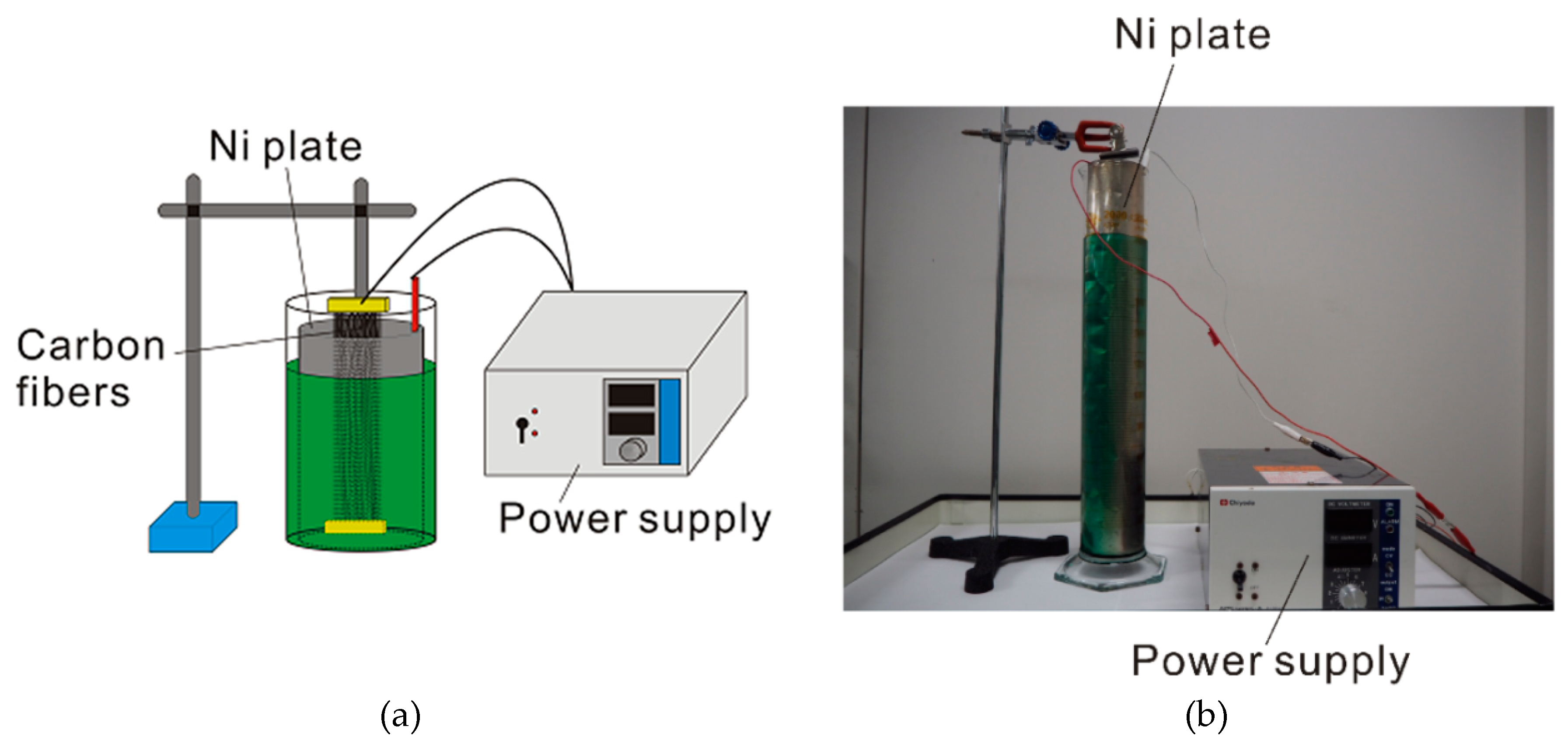
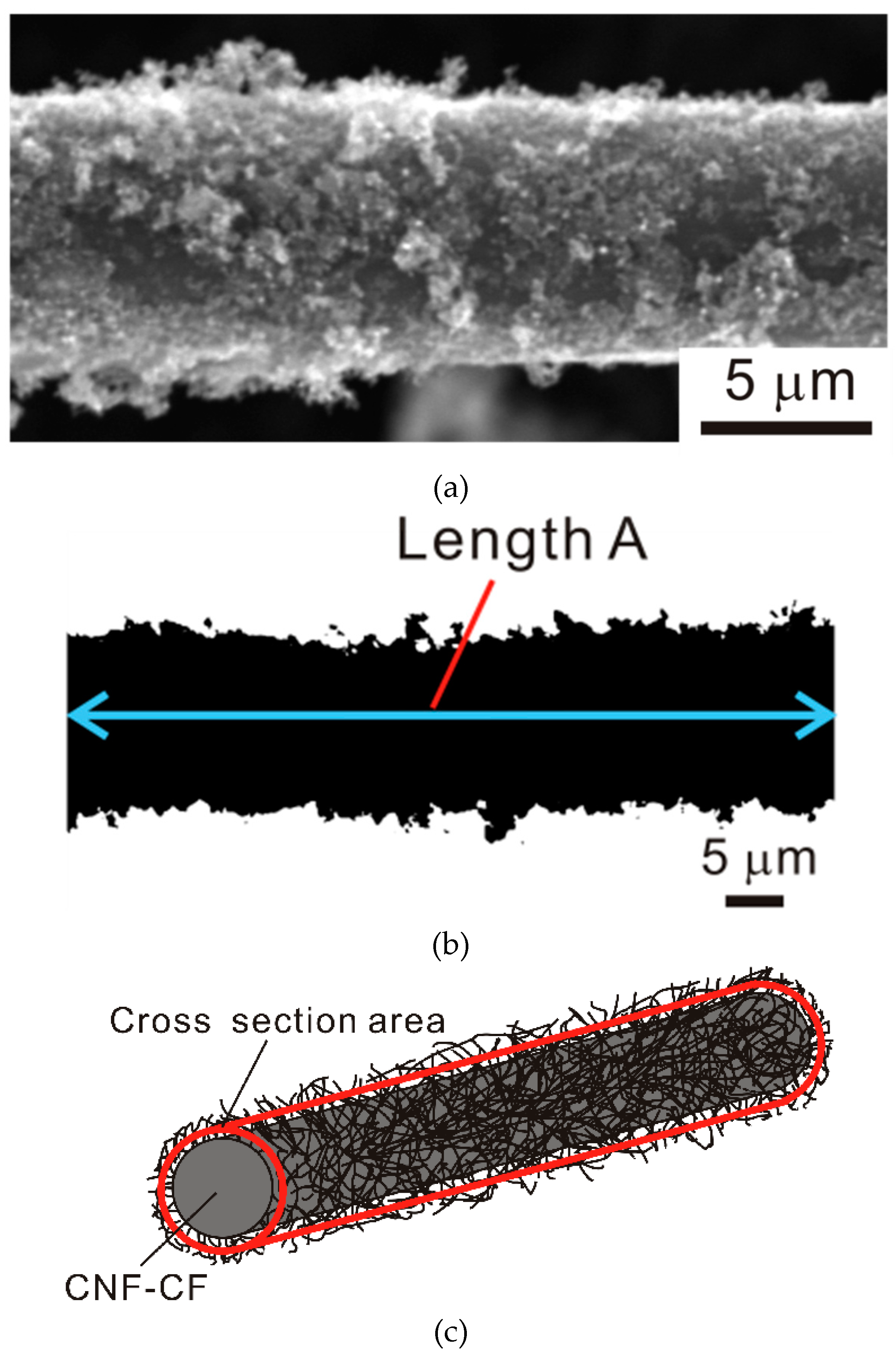
2.2. Preparation of CNF-CF and Measurement of Electric Resistance

In order to graft CNF on the CF surface (190 mm in length), Ni, as a catalyst for CNF grafting, was plated onto the surface of carbon fiber by the electrolytic Ni plating method. A schematic drawing and a photo image of Ni electrolytic plating methods are shown in Figure 1. The components of the plating bath consisted of Nickel sulfate hexahydrate (240 g/L), Nickel chloride hexahydrate (45 g/L), and Boracic acid (30 g/L). The carbon fiber, which is surrounded by the Ni plate, was connected to one end of the electrode and dipped in the plating bath. An inverter type DC power supply unit (APS-A012010, Chiyoda, Tokyo, Japan) was used in this study. The plating time was 20 s and the current density was 0.3 A. The carbon fiber is referred to as Ni-CF. The carbon fiber is referred to as Ni-CF. CNF was grafted onto CF by the chemical vapor deposition (CVD) system (MPCVD-70, Microphase, Tsukuba, Japan) at 600 °C for 30 min with ethanol flowing through at the rate of 2 mL/min. These CNF grafted carbon fiber is referred to as CNF-CF. The morphology of the surface of each fiber (CF, Ni-CF, CNF-CF) was examined by using a scanning electron microscope (SEM, JSM-6390LT, JEOL, Tokyo, Japan). The electric resistance value of each fiber was measured by the DC milli-ohm meter (GOM-802, GW Instek, Yokohama, Japan).

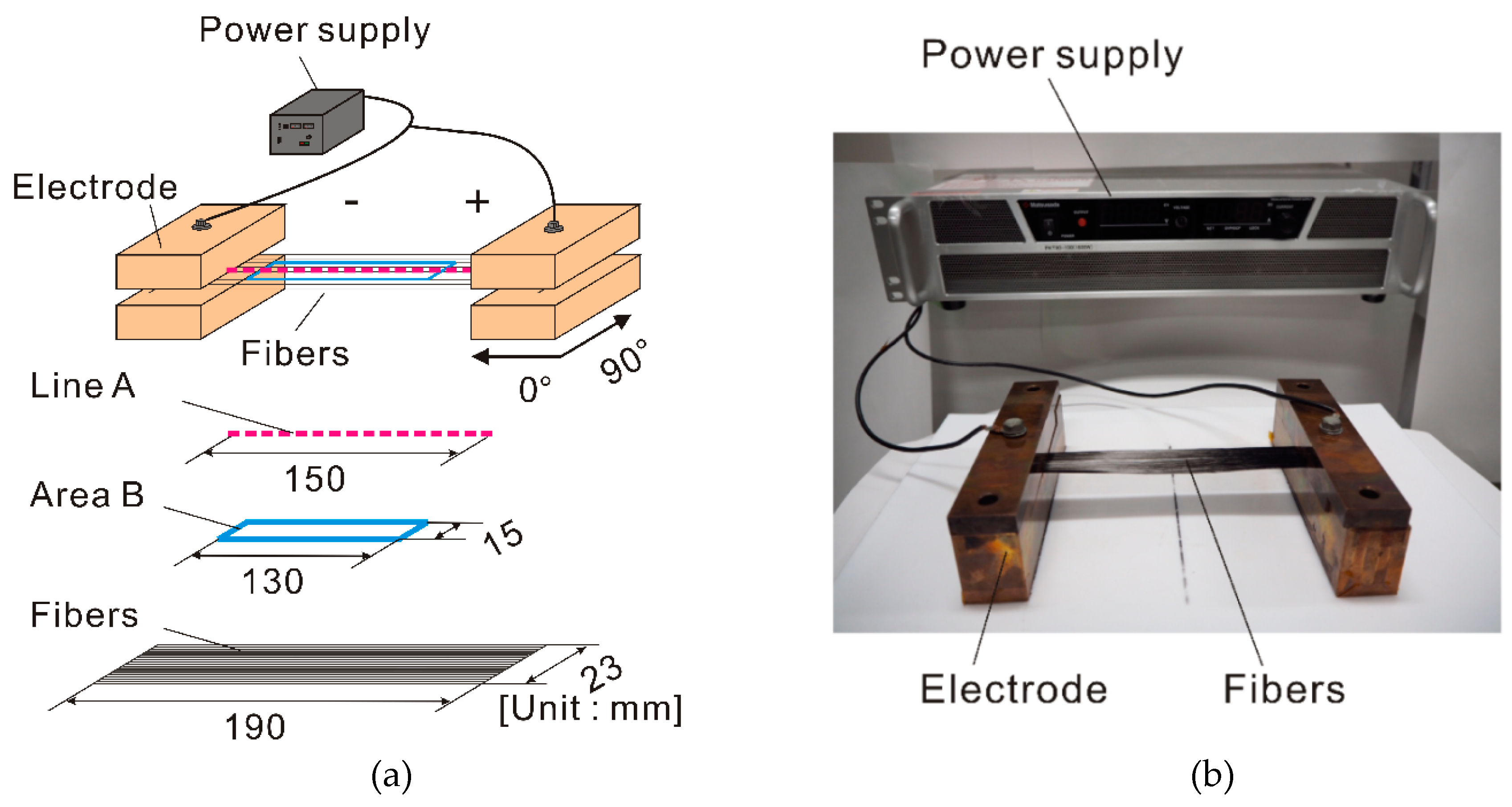
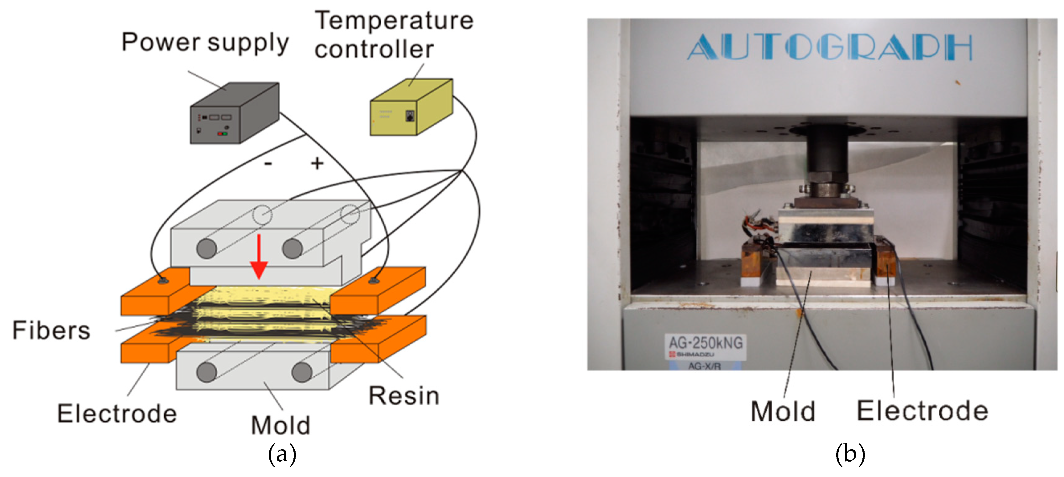
2.3. Direct Resistance Heating

In order to clarify the effect of CNF grafting on the temperature distribution of direct resistance heating of carbon fiber, the temperature distribution of each fiber was measured. A schematic drawing and a photo image for experimental setup of the temperature distribution measurement of each fiber are shown in Figure 2. A DC power supply (PKT80-100, Matsusada Precision, Kusatsu, Japan) is used in this study. As shown in Figure 2, electric power is supplied to each fiber through a copper electrode under a constant voltage condition of 13 V, and the temperature distribution of each fiber is measured using infrared thermography (R300SR-H, NEC Avio, Tokyo, Japan). Average temperature of Line A (150 mm in length) at 0° direction to each fiber and histogram of Area B (15 mm × 130 mm) was obtained from the thermal image.

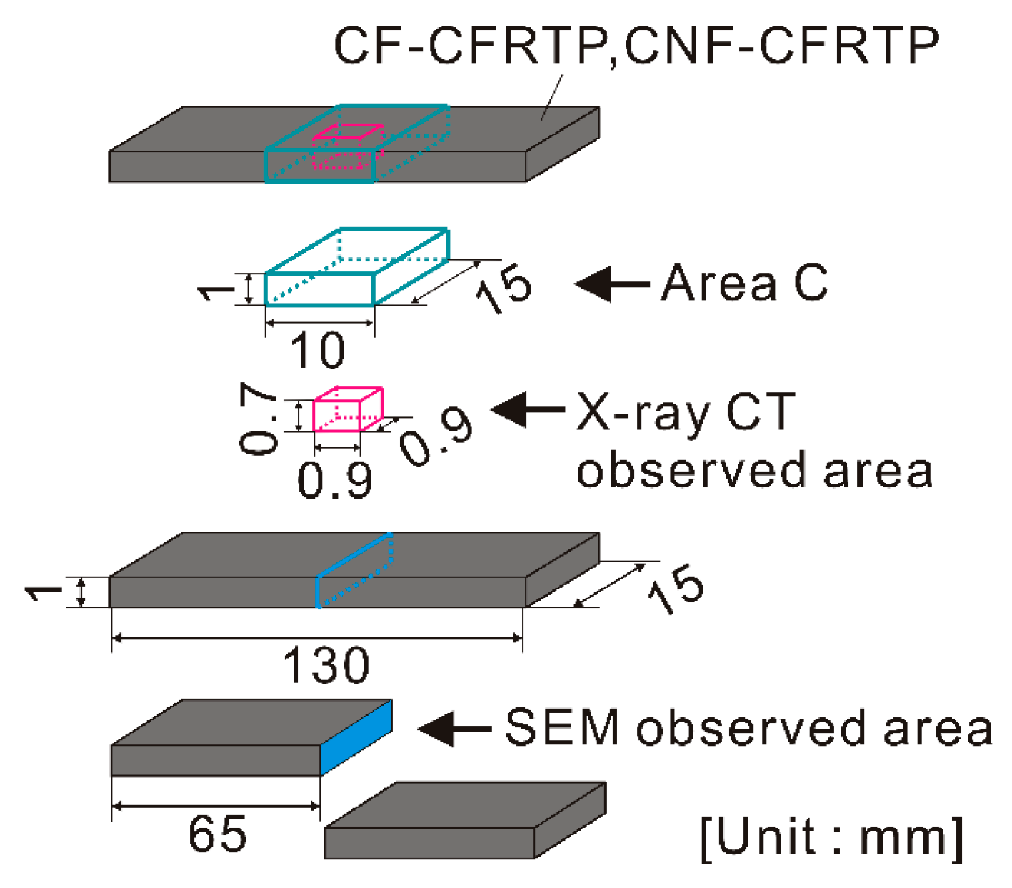
2.4. Molding of CFRTP

In order to clarify the effect of direct resistance heating to carbon fiber and CNF grafting on the impregnating properties of CFRTP, CFRTP ([0°]20 with the volume fraction (Vf) of 40%) was molded. CFRTP were fabricated using CF and CNF-CF (190 mm in length). Figure 3 shows a schematic drawing and a photo image of CFRTP hot press molding using direct resistance heating to carbon fiber. For reinforcing fiber of CFRTP, CF and CNF-CF were used. For comparison, CFRTP molded by only hot press without using direct resistance heating was also prepared. The molding of CFRTP is carried out by using a flat type mold attached to a universal precision testing machine (Autograph, AG-250 kN, Shimadzu, Kyoto, Japan). The molding conditions were molding temperature of 250 °C, molding pressure of 2 MPa and press holding time of 60 s. For the direct resistance heating to CF and CNF-CF, electric power is supplied to carbon fiber in the 0° longitudinal direction for 60 s under the constant electricity condition of 13 V by the DC power supply. After molding CFRTP, specimens with 130 mm in length and 15 mm in width were cut out. The interlaminar temperature history of the center part of CFRTP was measured using a K type thermocouple with a data logger (Midi Logger GL820, Graphtec, Yokohama, Japan).
The CFRTP molded by hot press with direct resistance heating and hot press without direct resistance heating were observed by using the X-ray microscope (Nano3DX, Rigaku, Tokyo, Japan), which can deliver 3D computed tomography (X-ray CT) images at high resolution for CFRP. Five observation regions (0.9 mm × 0.9 mm × 0.7 mm) randomly selected from Area C (15 mm × 10 mm × 1 mm, Figure 4) were observed. Their void content was calculated by image analysis processing. The cross sections of CFRTP were polished using a cross section polisher (CP, SM-09010, JEOL Ltd.) at a voltage of 5 kV for a polishing time of 10 h and observed by using SEM. Ten randomly selected images were taken from the SEM observed images and the void content of CFRTP was calculated by image analysis processing.
Hereafter, CFRTP molded by using CF and CNF-CF as the reinforced fiber are referred to as CF-CFRTP and CNF-CFRTP. Hot press molding and hot press mold with direct resistance heating are referred to as HP and DRH-HP, respectively.

3. Results and Discussion

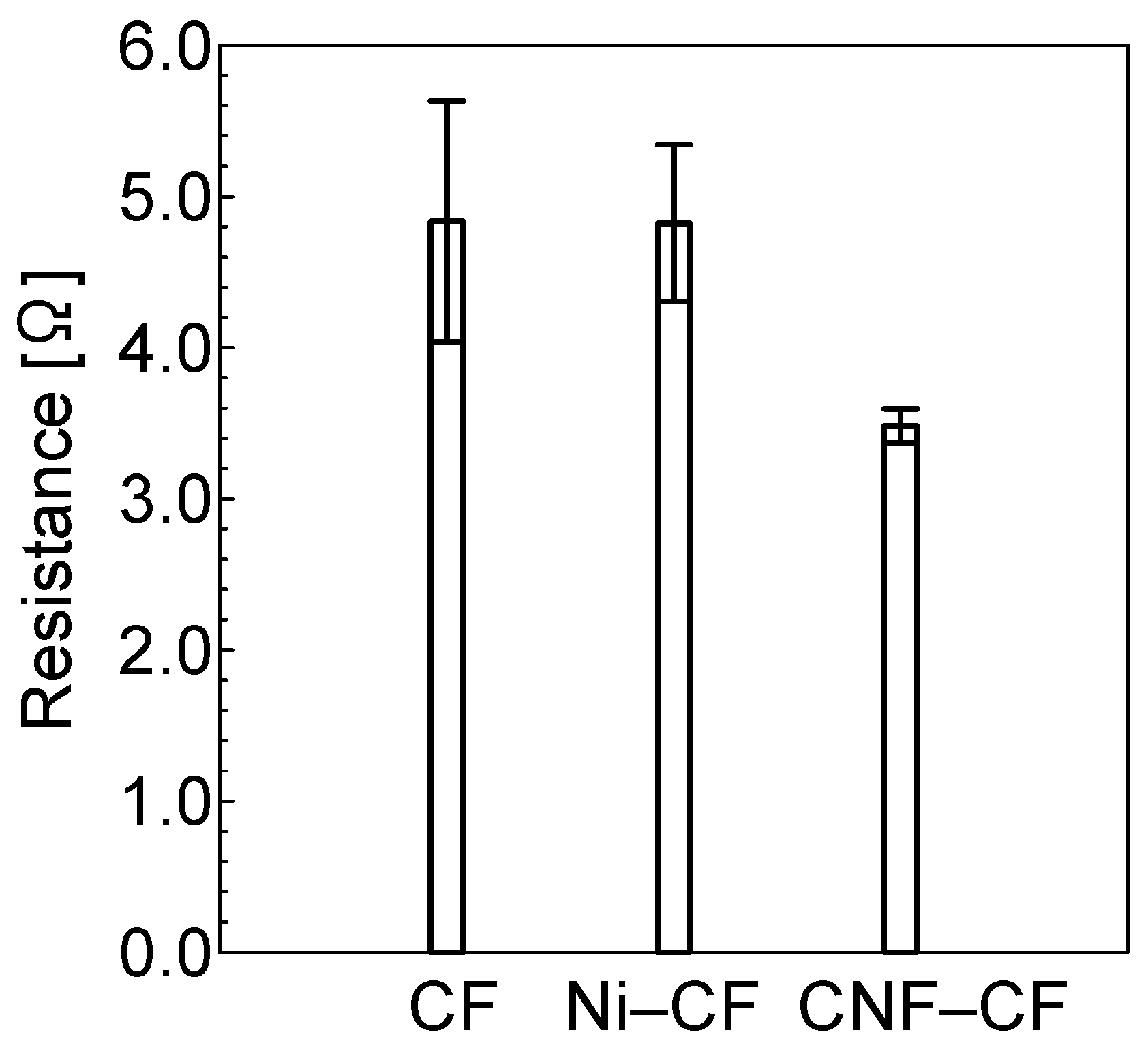
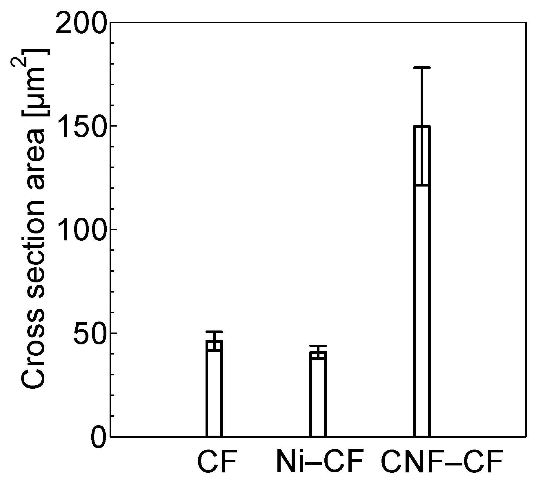
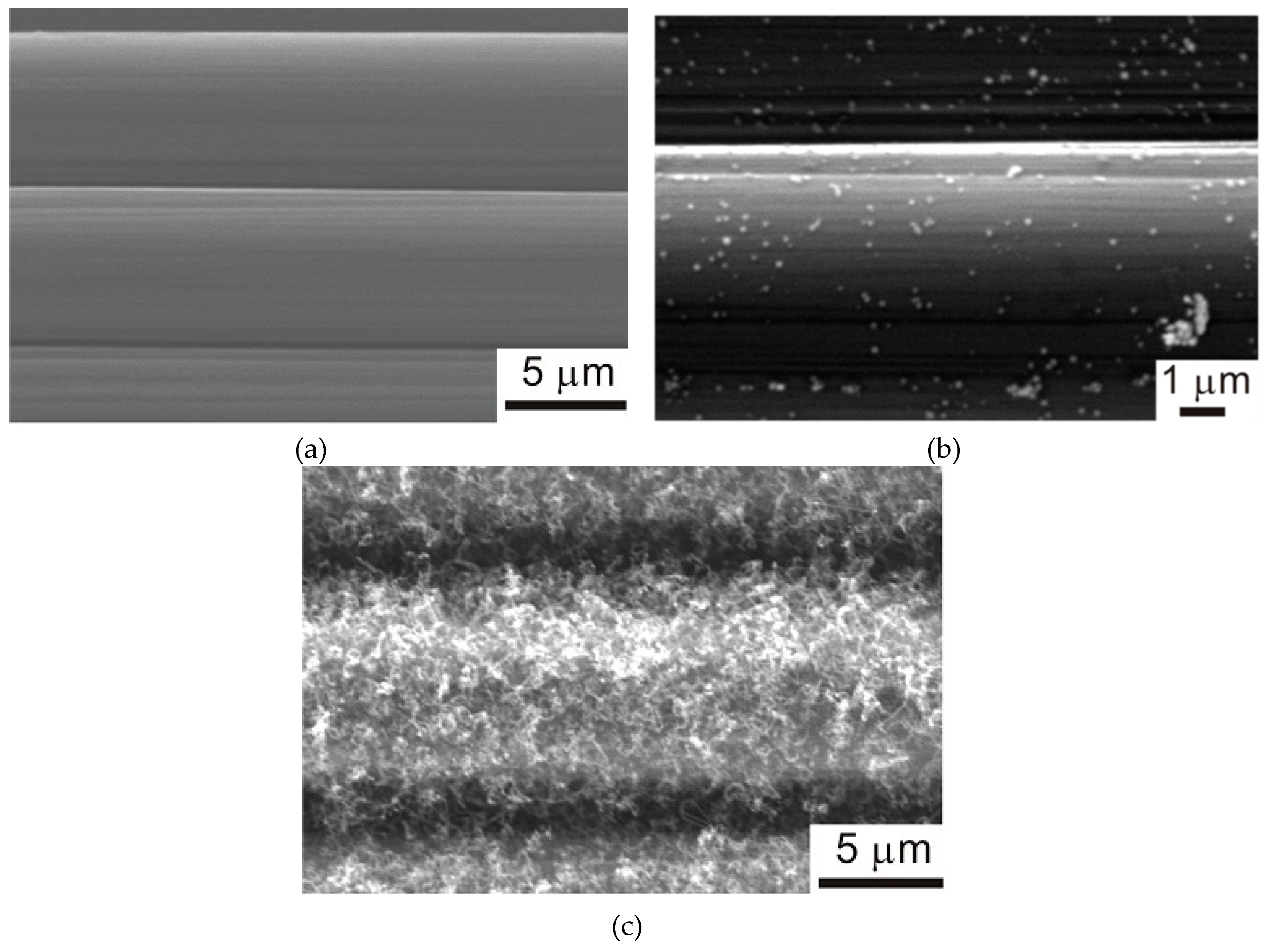
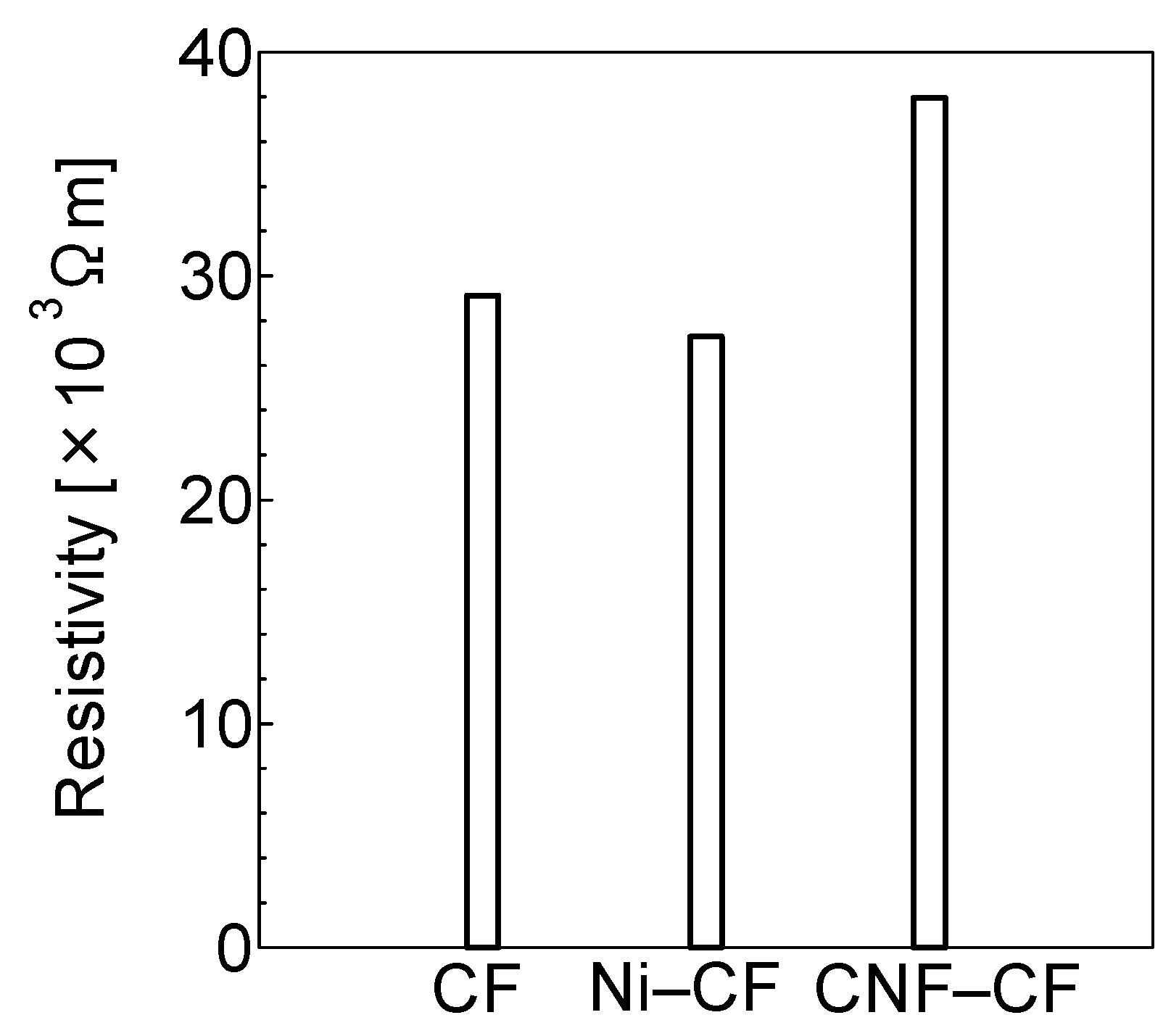
3.1. Observation of Each Fiber and Its Electric Resistance Value

SEM images of CF, Ni-CF, and CNF-CF are shown in Figure 5. As a result of line analysis by energy dispersive X-ray spectrometry (EDS) on Ni-CF using a transmission electron microscope (TEM), Ni was plated on the CF surface [20]. In CNF-CF, CNF is grafted on the CF surface. The electric resistance value of each fiber is shown in Figure 6. There was no significant difference between CF and Ni-CF, but CNF-CF showed lower electric resistance value by 28% than CF.
The schematic diagram of a method for calculating the cross-section area of CNF-CF is shown in Figure 7. Figure 7b shows binary image of a CNF-CF by image analysis processing. By using fiber length A and the binary area, the outer diameter and apparent cross section area were calculated. Figure 7c shows the schematic drawing of apparent cross section area of the CNF-CF obtained by this process. For CF and Ni-CF, the cross-section area was measured by using SEM images. The measured cross-section area of each fiber is shown in Figure 8. CNF-CF had a larger cross-section area than that of CF and Ni-CF due to CNF grafting on the CF surface. This largest cross section area of CNF-CF is considered to be the reason for the fact that CNF-CF has the smallest electric resistance value shown in Figure 6. The resistivity calculated simply by the apparent cross-sectional area is shown in Figure 9. CNF-CF showed higher resistivity value than CF and Ni-CF. It means that the resistivity of CNF grafted part is higher than that of CF itself. The reason for this result is that a lot of void (air) are exist between CNFs in the apparent cross-section area.

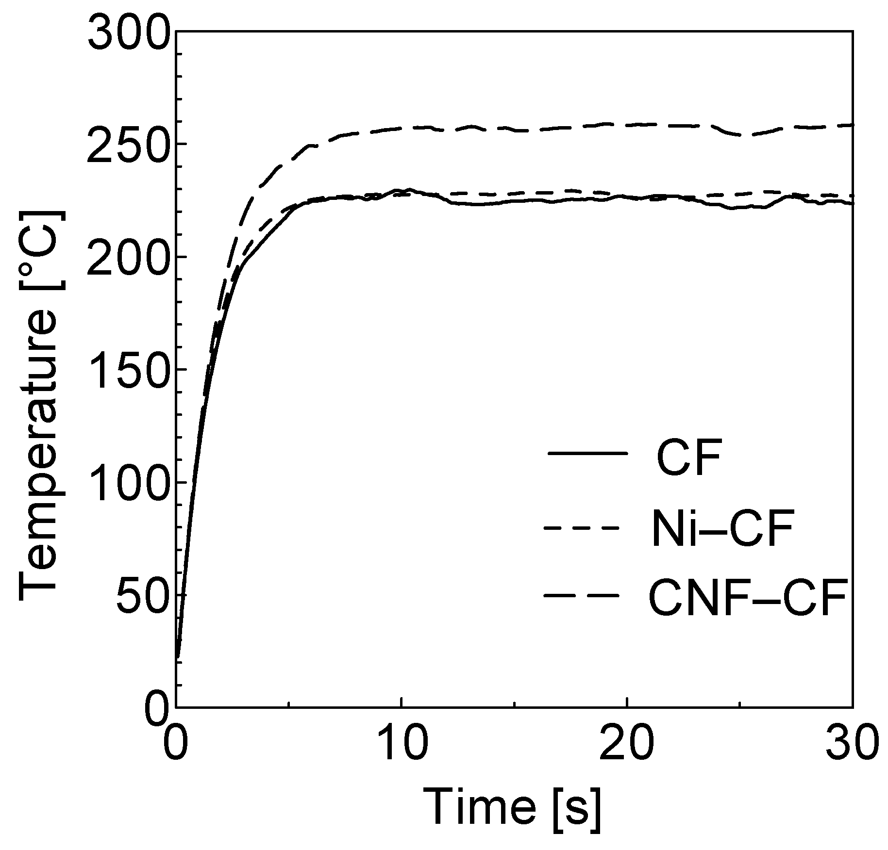
3.2. Heating Characteristic of Each Fiber at Direct Resistance Heating

Figure 10 shows the temperature distribution of each fiber when power is supplied with respect to 0° direction for 30 s under the constant voltage condition of 13 V, and the average temperature history on Line A in Figure 2 is shown in Figure 11. CNF-CF reached the highest temperature. The occupied percentage of heated area, that is higher than the melting point of PA6, 225 °C, is shown in Figure 12. In the case of CNF-CF, 99.9% of Area B was above 225 °C, while 74.9% and 77.2% are for CF and Ni-CF, respectively.
According to the first Joule’s law, with voltage V, the electric resistance value R and the time t; the resulting Joule heat is calculated by the following Equation (1).
Q = V 2 R t
In this study, since direct resistance heating was performed under constant voltage condition. Therefore, the Joule’s heat quantity can be obtained depends on the electric resistance value from Joule’s first law. As shown in Figure 6, CNF-CF showed lowest electric resistance value. This is considered to be the reason for the fact that CNF has the largest Joule heat and shows the larger area which is higher than the melting point.

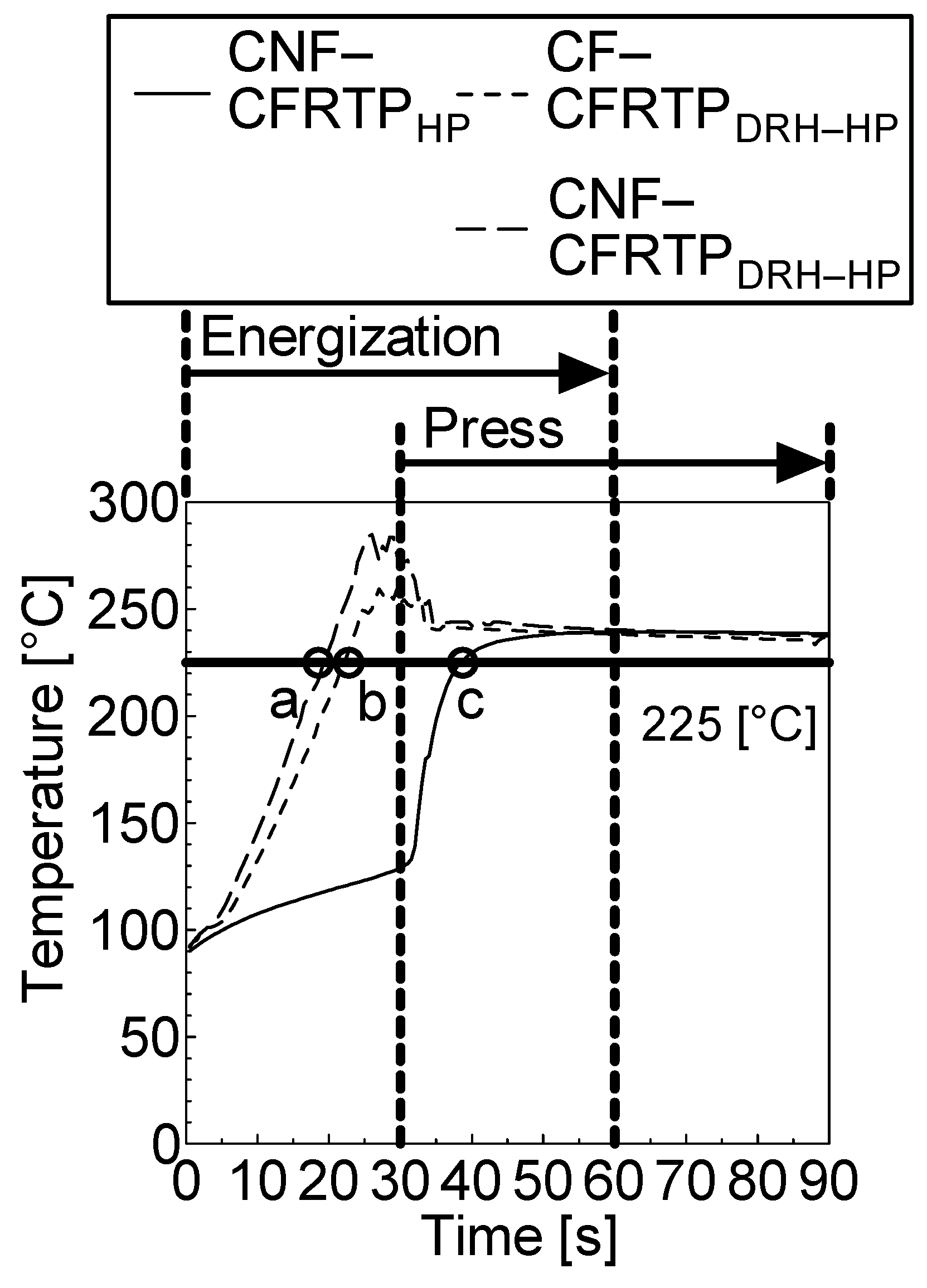
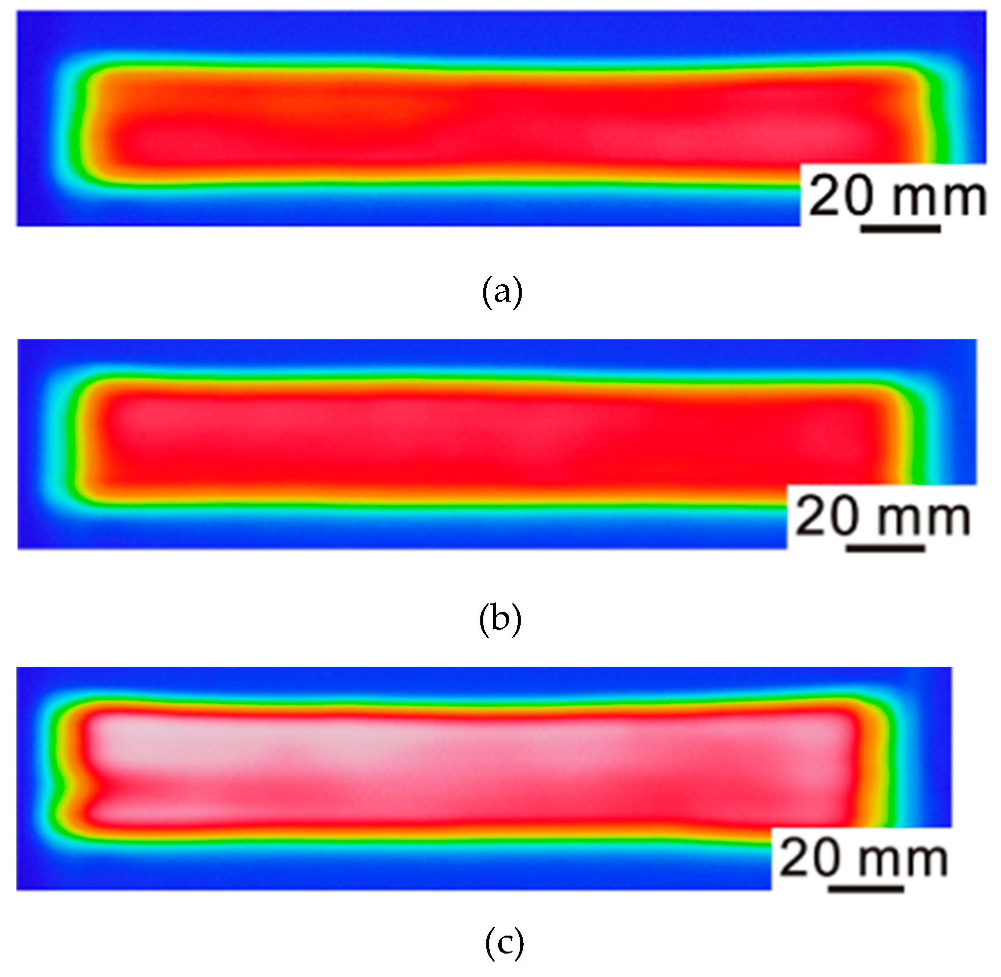
3.3. Interlaminar Temperature History of CFRTP

The interlaminar temperature histories of CFRTP molded with only HP for CNF-CF (CNF-CFRTPHP), CFRTP molded with DRH-HP for CF (CF-CFRTPDRH-HP), and CFRTP molded with DRH-HP for CNF-CF (CNF-CFRTPDRH-HP) are shown in Figure 13. The time to reach 225 °C (melting point of PA6) is 19 s for CNF-CFRTPDRH-HP, 25 s for CF-CFRTPDRH-HP, and 38 s for CNF-CFRTPHP. CNF-CFRTPDRH-HP reaches the temperature of more than 225 °C faster than CNF-CFRTPHP. In addition, CNF-CFRTPDRH-HP reaches a higher reached temperature than CF-CFRTPDRH-HP until press starts. Due to the higher temperature of CNF-CF than CF by direct resistance heating, CNF-CFRTPDRH-HP is considered to reach higher temperature. After pressurizing, however, there is no significant difference of temperature histories because of the heat transfer to the matrix resin.

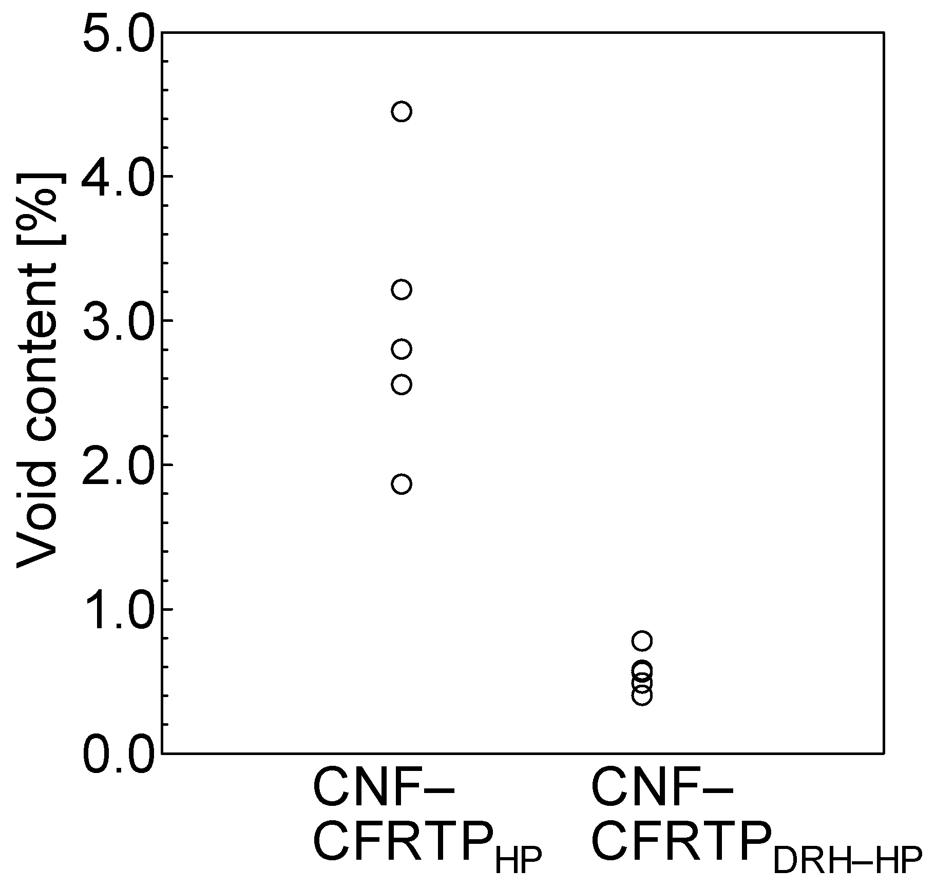
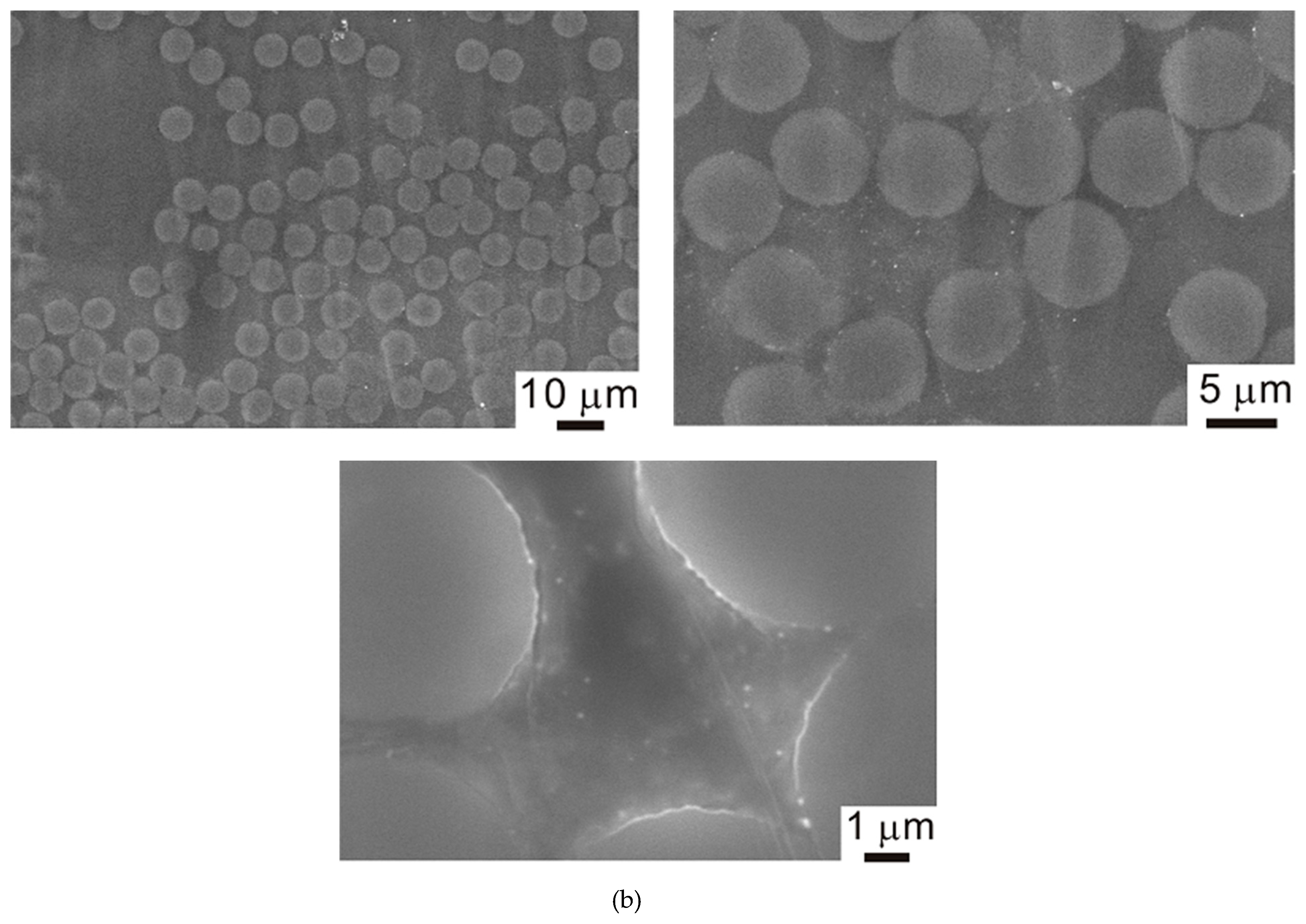
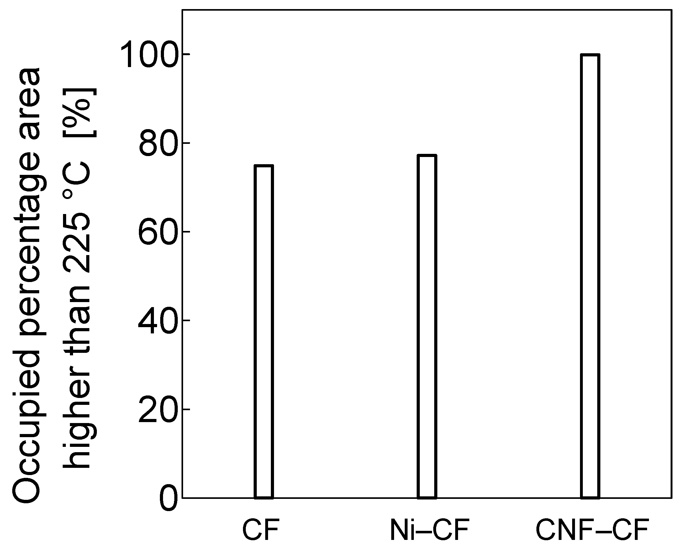
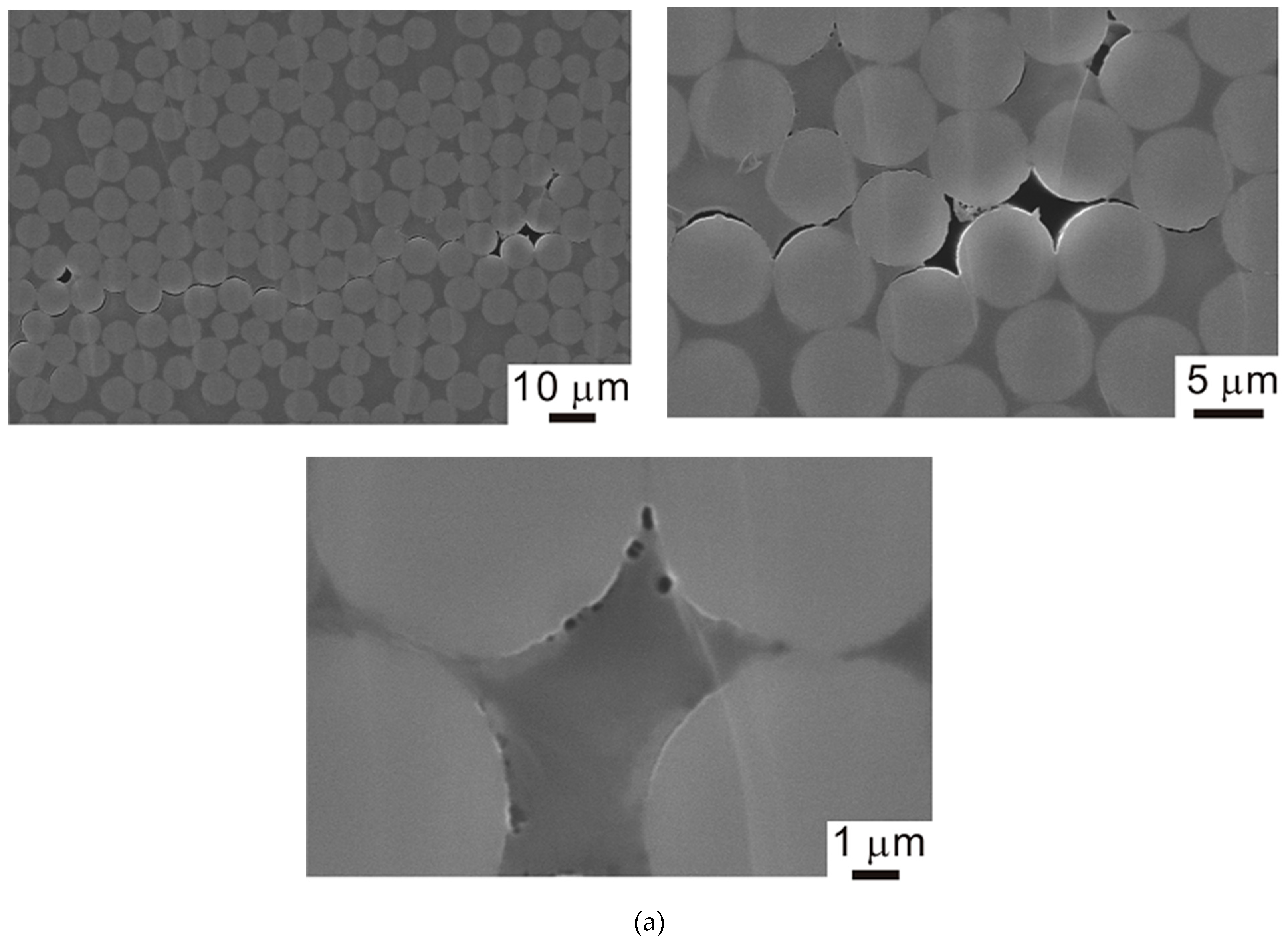
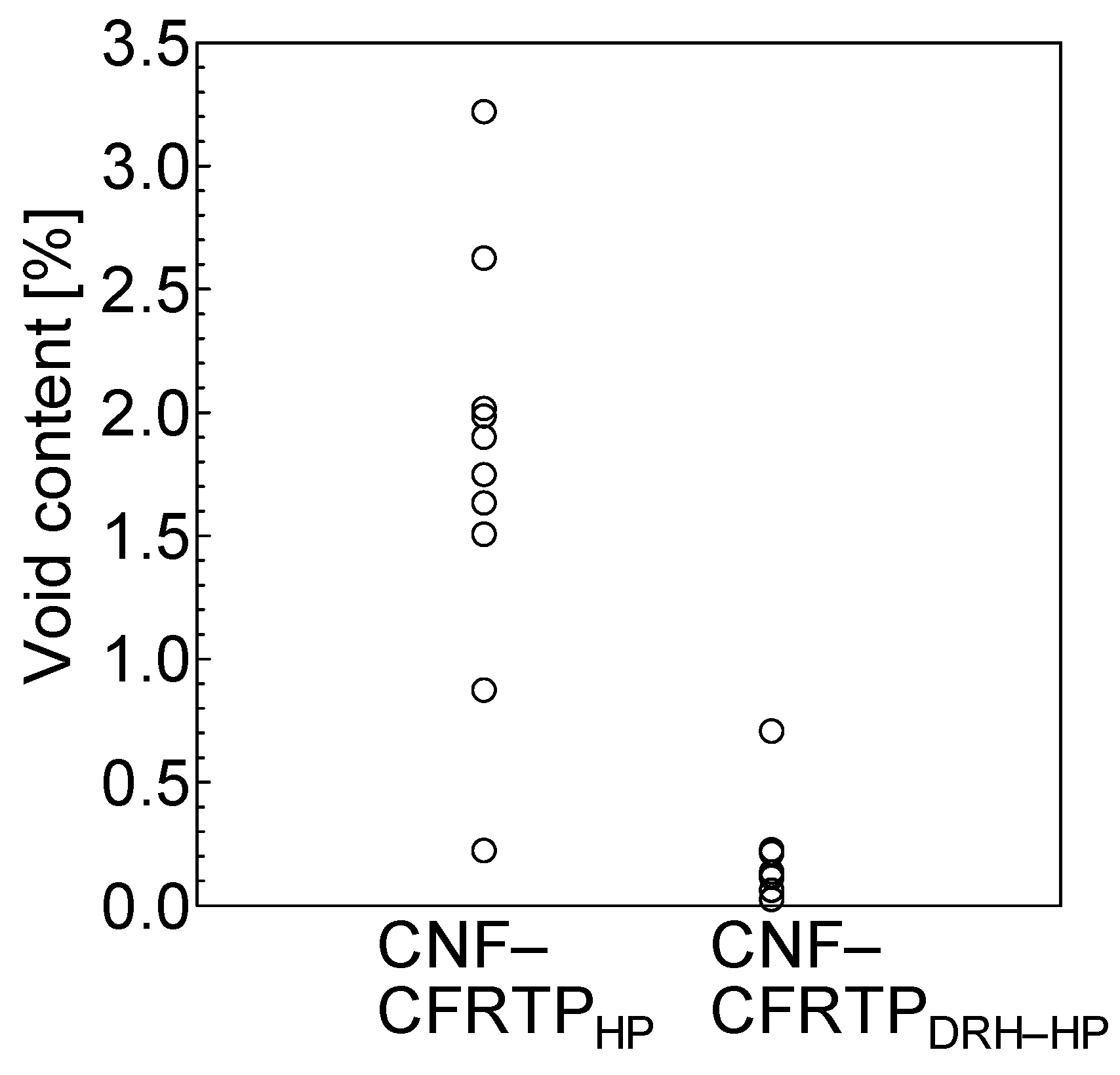
3.4. Effect of Direct Resistance Heating on Impregnating Properties of CFRTP

X-ray microscope images and extracted void images of CNF-CFRTP molded by HP and DRH-HP are shown in Figure 14. The void content of CNF-CFRTP molded by HP and DRH-HP observed with X-ray microscope is shown in Figure 15. CFRTP molded by DRH-HP (CNF-CFRTPDRH-HP) showed a lower void than CFRTP molded by only HP (CNF- CFRTPHP).
As shown in Figure 13, the interlaminar temperature of CFRTP molded by DRH-HP reaches the melting point of PA6 faster than CFRTP molded with only HP, as the melt viscosity of PA6 shows lower melt viscosity as the temperature increases [21]. The melt viscosity of PA6 increased in CNF-CFRTPDRH-HP, as compared to CNF-CFRTPHP because of the higher temperature and longer time over the melting point of PA6, as shown in Figure 13. Direct resistance heating of carbon fiber itself can promote the impregnation of resin to the carbon fiber, and CFRTP with the low void ratio can be obtained by using direct resistance heating.

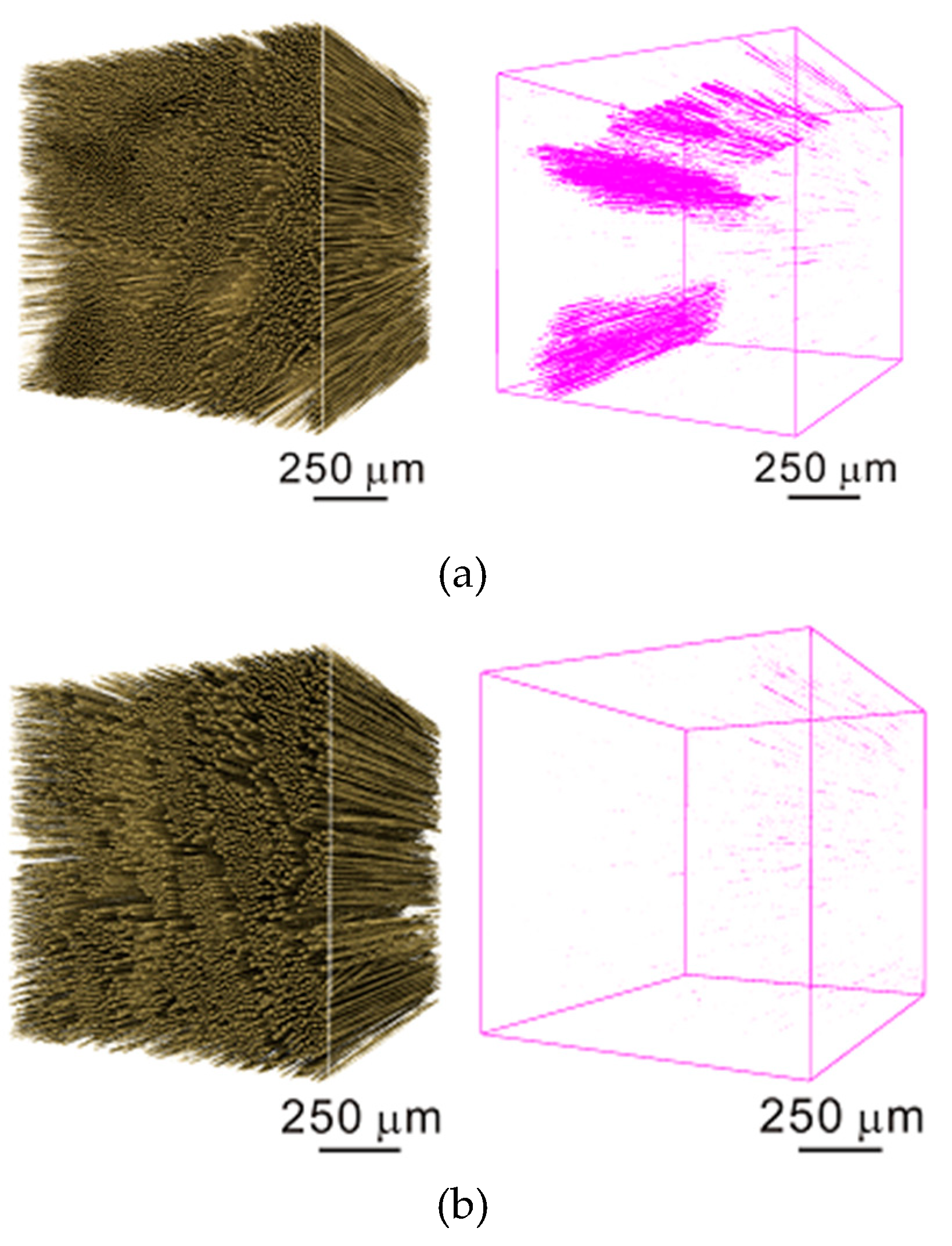
3.5. Effect of CNF on Impregnating Properties of CFRTP

SEM images of CF-CFRTP and CNF-CFRTP molded by DRH-HP are shown in Figure 16. The void content of CNF-CFRTPDRH-HP and CF-CFRTPDRH-HP are shown in Figure 17. CFRTP molded using CNF-CF as reinforcing fiber (CNF-CFRTPDRH-HP) has lower void content than CFRTP molded using CF as reinforcing fiber (CF-CFRTPDRH-HP).
As shown in Figure 6 CNF-CF showed lower electric resistance value than CF. By using CNF-CF for the heating elements, due to the higher temperature than melting point of PA6 of 225 °C and larger area above 225 °C, the viscosity of melted PA6 became lower and CNF-CFRTPDRH-HP showed better impregnation compared with CF-CFRTPDRH-HP. For the hot press molding with the direct resistance heating to reinforcing fiber of CFRTP, CNF-CF is suitable compared to CF.

4. Conclusions

In this study, to develop a molding method of CFRTP with low void contents, direct resistance heating to carbon fiber is applied to hot press molding. Carbon nanofilaments (CNF) grafted carbon fiber is also used for self-heating member and the effect of direct resistance heating and CNF grafting to carbon fiber surface on impregnation properties of CFRTP were investigated. The investigation yielded the following conclusions.
  • CNF grafted carbon fiber shows a lower electric resistance value than carbon fiber. Due to this, CNF grafted carbon fiber can be heated faster than carbon fiber by direct resistance heating under constant voltage conditions.
  • Compared to CFRTP molding by only hot press, hot press molding with direct resistance heating to CNF-CF can mold CFRTP with low void content.
  • For hot press molding with the direct resistance heating to reinforcing fiber of CFRTP, CNF grafted carbon fiber is suitable compared to carbon fiber.

Author Contributions

Conceptualization, K.T.; Methodology, K.T.; Investigation, R.H. and M.T.; Writing-Original Draft Preparation, R.H.; Writing-Review & Editing, K.T.; Supervision, T.K.; Project Administration, K.T.; Funding Acquisition, K.T. and T.K.

Funding

This work was partially supported by KAKENHI (Japan Society for the Promotion of Science, Grant-in-Aid for Scientific Research (B)) (26289011) and a research project on “Research and Development Center for Advanced Composite Materials” of Doshisha University and MEXT (the Ministry of Education, Culture, Sports, Science and Technology, Japan)—Supported Program for the Strategic Research Foundation at Private Universities, 2013–2017, the project S1311036.

Conflicts of Interest

The authors declare no conflict of interest.

References

  1. International Energy Agency. CO2 Emission from Fuel combustion Highlights 2014; IEA: Paris, France, 2014; pp. 7–12. [Google Scholar]
  2. Feraboli, P.; Masini, A.; Taraborrelli, L.; Pivetti, A. Integrated development of CFRP structures for a topless high performance vehicle. Compos. Struct. 2007, 78, 495–506. [Google Scholar] [CrossRef]
  3. Holmes, M. Carbon fibre reinforced plastics market continues growth path. Reinf. Plast. 2013, 57, 24–29. [Google Scholar] [CrossRef]
  4. Galoone, A.; Ariante, M.; Fusco, G.; Flores, F.; Bizzarro, G.; Zinno AProta, A. Thermoplastic composite structure for mass transit vehicle: Design, computational engineering and experimental validation. In Proceedings of the 15th Edition of the European Conference on Composite Materials ECCM15, Venice, Italy, 24–28 June 2012; pp. 24–28. [Google Scholar]
  5. Baba, S. Continuous fiber reinforced thermoplastics CFRTP-GFRTP and market. J. JSPE 2015, 81, 503–506. [Google Scholar]
  6. Enoki, S.; Iwamoto, K.; Harada, R.; Tanaka, K.; Katayama, T. Heating properties of carbon fibers by direct resistance heating. WIT Tans. Build. Environ. 2012, 124, 239–248. [Google Scholar]
  7. Enoki, S.; Moriito, K.; Tanaka, K.; Katayama, T. CFRTP molding method of the three-dimensional shape by using direct resistance heating to carbon fiber. HPSM 2014, 137, 273–282. [Google Scholar] [Green Version]
  8. Tanaka, K.; Okada, K.; Katayama, T. Effect of water surface treatment on tensile shear strength of resistance welded CFRTP. J. Soc. Mater. Sci. 2018, 67, 284–290. [Google Scholar] [CrossRef]
  9. Cesano, F.; Bertarione, S.; Scarano, D.; Zecchina, A. Connecting carbon fibers by means of catalytically grown nanofilaments: Formation of carbon-carbon composites. Chem Mater. 2005, 17, 5119–5123. [Google Scholar] [CrossRef]
  10. Pradhan, D.; Sharon, M. Carbon nanotubes, nanofilaments and nanobeads by thermak chemical vapor deposition process. Mater. Sci. Eng. 2002, B96, 24–28. [Google Scholar] [CrossRef]
  11. Calvo, M.; Arenillas, A.; Garcia, R.; Moinelo, S. Growth of carbon nanofilaments on coal foams. Fuel 2009, 88, 46–53. [Google Scholar] [CrossRef]
  12. Greef, N.; Zhang, L.; Magrez, A.; Forro, L.; Locquet, J.; Verpoest, I.; Seo, J. Direct growth of carbon nanotubes on carbon fibers:effect of the CVD parameters on the degradation of mechanical properties of carbon fibers. Diam. Relat. Mater. 2015, 51, 39–48. [Google Scholar] [CrossRef]
  13. Naito, K.; Yang, J.; Xu, Y.; Kagawa, Y. Enhancing the thermal conductivity of polyacrylonitrile-and pitch-based carbon fibers by grafting carbon nanotubes on them. Carbon 2010, 48, 1849–1857. [Google Scholar] [CrossRef]
  14. Qian, H.; Bismarck, A.; Greenhalgh, E.; Shaffer, M. Carbon nanotube grafted carbon fibres: A study of wetting and fibre fragmentation. Compos. Part. A 2010, 41, 1107–1114. [Google Scholar] [CrossRef] [Green Version]
  15. Gong, X.; Liu, J.; Baskaran, S.; Voise, D.; Young, J. Surfactant-assisted processing of carbon nanotube/polymer composites. Chem. Mater. 2000, 12, 1049–1052. [Google Scholar] [CrossRef]
  16. Thostenson, E.; Ren, Z.; Chou, T. Advances in the science and technology of carbon nanotubes and their composites: A review. Key Eng. Mater. 2001, 61, 1899–1912. [Google Scholar] [CrossRef]
  17. Volder, M.; Tawfick, S.; Baughman, R.; Hart, A. Carbon nanotubes: Present and future commercial applications. Science 2013, 339, 535–539. [Google Scholar] [CrossRef] [PubMed]
  18. Yu, B.; Jiang, Z.; Tang, Z.; Yue, C.; Yang, J. Enhanced interphase between epoxy matrix and carbon fiber with carbon nanotube-modified silane coating. Kye Eng. Mater. 2014, 99, 131–140. [Google Scholar] [CrossRef]
  19. Tanaka, K.; Tanaka, Y.; Katayama, T. Effect of carbon nanotube grafting on tensile shear strength of resistance welded CFRTP. J. Soc. Mater. Sci. 2016, 65, 727–732. [Google Scholar] [CrossRef]
  20. Tanaka, K.; Uzumasa, K.; Katayama, T. Influence of CNT grafting on carbon fibers on impact properties of CFRTP laminate. Key Eng. Mater. 2018, 774, 410–415. [Google Scholar] [CrossRef]
  21. Tanaka, K.; Sone, M.; Katayama, T. Evaluation of tensile property of CF/PA6 at molding temperature. J. Soc. Mater. Sci. 2018, 67, 460–467. [Google Scholar] [CrossRef]
Figure 1. Schematic drawing and photo image of Ni electrolytic plating method. (a) Schematic drawing. (b) Photo image.
Jcs 03 00014 g001
Figure 2. Schematic drawing and photo image for experimental setup of the temperature distribution measurement of each fiber. (a) Schematic drawing. (b) Photo image.
Jcs 03 00014 g002
Figure 3. Schematic drawing and photo image of carbon fiber reinforced thermoplastics (CFRTP) hot press molding using direct resistance heating to carbon fiber. (a) Schematic drawing. (b) Photo image.
Jcs 03 00014 g003
Figure 4. Observed area of X-ray microscope and SEM.
Jcs 03 00014 g004
Figure 5. SEM images of each carbon fiber. (a) Carbon fiber (CF). (b) Ni-CF. (c) Carbon nanofilaments (CNF)-CF.
Jcs 03 00014 g005
Figure 6. Electric resistance of each carbon fiber. (N = 6, mean ± S. D.).
Jcs 03 00014 g006
Figure 7. Schematic diagram for calculating the cross-section area of CNF-CF. (a) SEM image of CNF-CF. (b) Binary image of CNF-CF. (c) Schematic drawing of apparent cross section area of CNF-CF.
Jcs 03 00014 g007
Figure 8. Cross section area of each carbon nanofilaments. (N = 6, mean ± S. D.).
Jcs 03 00014 g008
Figure 9. Resistivity of each carbon fiber.
Jcs 03 00014 g009
Figure 10. Temperature distribution of each carbon nanofilaments. (a) CF. (b) Ni-CF. (c) CNF-CF.
Jcs 03 00014 g010
Figure 11. Temperature history of each carbon nanofilaments.
Jcs 03 00014 g011
Figure 12. Temperature histogram of carbon nanofilaments.
Jcs 03 00014 g012
Figure 13. Temperature history of CF-CFRTP and CNF-CFRTP.
Jcs 03 00014 g013
Figure 14. X-ray microscope images and extracted void images of CNF-CFRTP. (a) Hot press molding (HP). (b) Hot press mold with direct resistance heating (DRH-HP).
Jcs 03 00014 g014
Figure 15. Void content of CNF-CFRTP measured by X-ray microscope.
Jcs 03 00014 g015
Figure 16. SEM image of CF-CFRTP and CNF-CFRTP molded by DRH-HP. (a) CF-CFRTP. (b) CNF-CFRTP.
Jcs 03 00014 g016aJcs 03 00014 g016b
Figure 17. Void content of CF-CFRTP and CNF-CFRTP calculated by using SEM images.
Jcs 03 00014 g017

