Article

Axial Response of Concrete-Filled FRP Tube (CFFT) Columns with Internal Bars

by
Asmaa Abdeldaim Ahmed
and
Radhouane Masmoudi
*
Department of Civil Engineering, University of Sherbrooke, Sherbrooke, QC J1K 2R1, Canada
*
Author to whom correspondence should be addressed.
J. Compos. Sci. 2018, 2(4), 57; https://doi.org/10.3390/jcs2040057
Submission received: 26 July 2018 / Revised: 31 August 2018 / Accepted: 5 September 2018 / Published: 24 September 2018
(This article belongs to the Special Issue Use of Fiber-Reinforced Polymer Composites in Civil Engineering)

Abstract

:
This paper aims at investigating the general axial behavior of long circular concrete-filled, fiber-reinforced polymer (FRP) tube (CFFT) columns internally reinforced with different longitudinal rebars. A total of seven CFFT and three reinforced concrete (RC) columns served as control specimens for comparisons and were constructed and tested under cyclic axial loading until failure. The test parameters were: (1) internal reinforcement type (steel, glass fiber-reinforced polymer (GFRP) or carbon fiber-reinforced polymer (CFRP)) and amount; (2) GFRP tube thicknesses; and (3) nature of loading. All columns had 1900-mm in height and 213-mm in diameter. Examination of the test results has led to a number of significant conclusions in regards to the trend and ultimate condition of the axial stress-strain behavior, mode of failure of tested CFFT columns, and plastic strains. As expected, an increase in the FRP tube thickness (or stiffness) resulted in an increase in the strength and strain enhancement ratios. The validity of the available design provisions for predicting the ultimate load-carrying capacity of tested columns is also highlighted.

1. Introduction

Over the past couple of decades, fiber-reinforced polymer (FRP) composites have been used for enhancing the behavior of reinforced concrete (RC) members, including several advantages such as favorable strength-to-weight ratio, non-corrosive characteristics, and reduced long-term maintenance costs. An important application of FRP composites is as a confining material for concrete, both in the seismic retrofit of existing RC columns and in the construction of concrete-filled FRP tubes (CFFTs) as earthquake-resistant columns in new construction. The FRP tube acts as a stay-in-place structural formwork, a noncorrosive reinforcement for the concrete for flexure and shear using the multidirectional fiber orientation, which provides confinement to the concrete in compression, and the contained concrete is protected from the intrusion of moisture with corrosive agents that could otherwise deteriorate the concrete core [1]. The majority of existing studies have focused on the monotonic axial stress-strain behavior of FRP-confined unreinforced concrete, which has led to the development of over 80 stress-strain models (e.g., [2,3,4,5,6,7]). In contrast, only a few studies have so far investigated the behavior of FRP-confined concrete under axial cyclic compression [8,9,10,11,12,13,14] and to the best knowledge of the authors, only two analytical cyclic stress-strain models [12,15] have been proposed in the literature. Meanwhile, there is a distinct lack of research on the axial cyclic stress-strain behavior of full-scale CFFT columns with internal reinforcement bars. It is worth mentioning that the existing stress-strain models of FRP-confined concrete were developed almost exclusively based on results of specimens with height-to-diameter ratio (h/d = 2) [14]. It is, therefore, important to examine the stress-strain behavior of full-scale CFFT columns reinforced with and without internal bars with high (h/d) ratios and to develop new analytical models to describe this behavior under axial cyclic compression loading.
Nowadays, FRP bars as an alternative to steel bars have emerged as a realistic and cost-effective solution to overcome the corrosion problems. FRP bars offer many advantages over conventional steel bars, including a density of one-quarter to one-fifth that of steel, greater tensile strength than steel, and no corrosion even in harsh chemical environments. Previous experimental studies indicated that the compression behavior of concrete columns reinforced with GFRP reinforcements has been similar to that with steel, but with less contribution of FRP longitudinal bars to strength capacity [16,17,18,19,20]. These studies also showed the applicability of exclusively reinforcing the columns with FRP bars and subjected them to concentric load. Using FRP bars, therefore, instead of conventional steel bars in the CFFT columns, can provide a step forward to develop a promising totally corrosion-free new structural system. Nonetheless, the axial behavior of FRP bars as longitudinal reinforcement in compression members has been quite limited, especially for the CFFT columns. To the best knowledge of the authors, there is no literature to date addressing the behavior of FRP-reinforced full-scale CFFT columns under axial cyclic compression loading. This paper reports on an experimental investigation that was undertaken to address this important research gap. This paper presents the test results of seven CFFT and three reinforced concrete (RC) columns reinforced longitudinally with steel or GFRP and CFRP bars tested under monotonic and cyclic axial compression loads. A discussion on the influence of the main test parameters in the observed behaviors is provided. Furthermore, the validity of the available design provisions for predicting the ultimate load capacity of tested columns is also highlighted.

2. Review of Codes and Design Guidelines

The North American codes use the form of Equation (1) to compute the theoretical nominal axial load capacity, (Po), of the conventional RC column reinforced with steel under concentric loading.
P o = k c f c   ( A g A s ) + f y A s .
where Ag is the gross sectional area of concrete, f c is the design ultimate concrete strength, fy and As are the yielding strength and area of the steel reinforcement bars, receptively. The parameter kc is defined as the ratio between the in-place strength of concrete to the concrete cylinder strength, ( f co / f c ). The difference is attributed to the size effect, shape, and concrete casting practice between columns and concrete cylinders, a value of 0.85 is being suggested for kc [12]. The two Canadian codes CSA-S6-06 [21] and CSA-A23.3 [22] provide similar equations as in the ACI 318 [23], except for introducing a material resistance factor for steel and concrete instead of the strength reduction factor specified in the ACI 318 [23]. In addition, the Canadian codes use the factor α1 instead of kc, which depends on the value of the unconfined concrete compressive strength. The ACI 440.R1 [24], CSA S806 [25], and S6-06 [21] were used to calculate the maximum loading carrying capacity for the FRP-reinforced control specimens. However, the contribution of FRP bars on the ultimate capacity of the columns is neglected, as specified by the design codes. For the specimens confined with FRP tubes, the ACI 440.2R [1] and the two Canadian codes (CSA S806 [25], S6-06 [21]) use the same equations of the conventional steel (RC) columns to predict the compressive strength but using ( f cc ) instead of ( f c ). Table 1 summarizes axial load-carrying capacity design provision equations for the FRP confined concrete columns.

3. Experimental Work
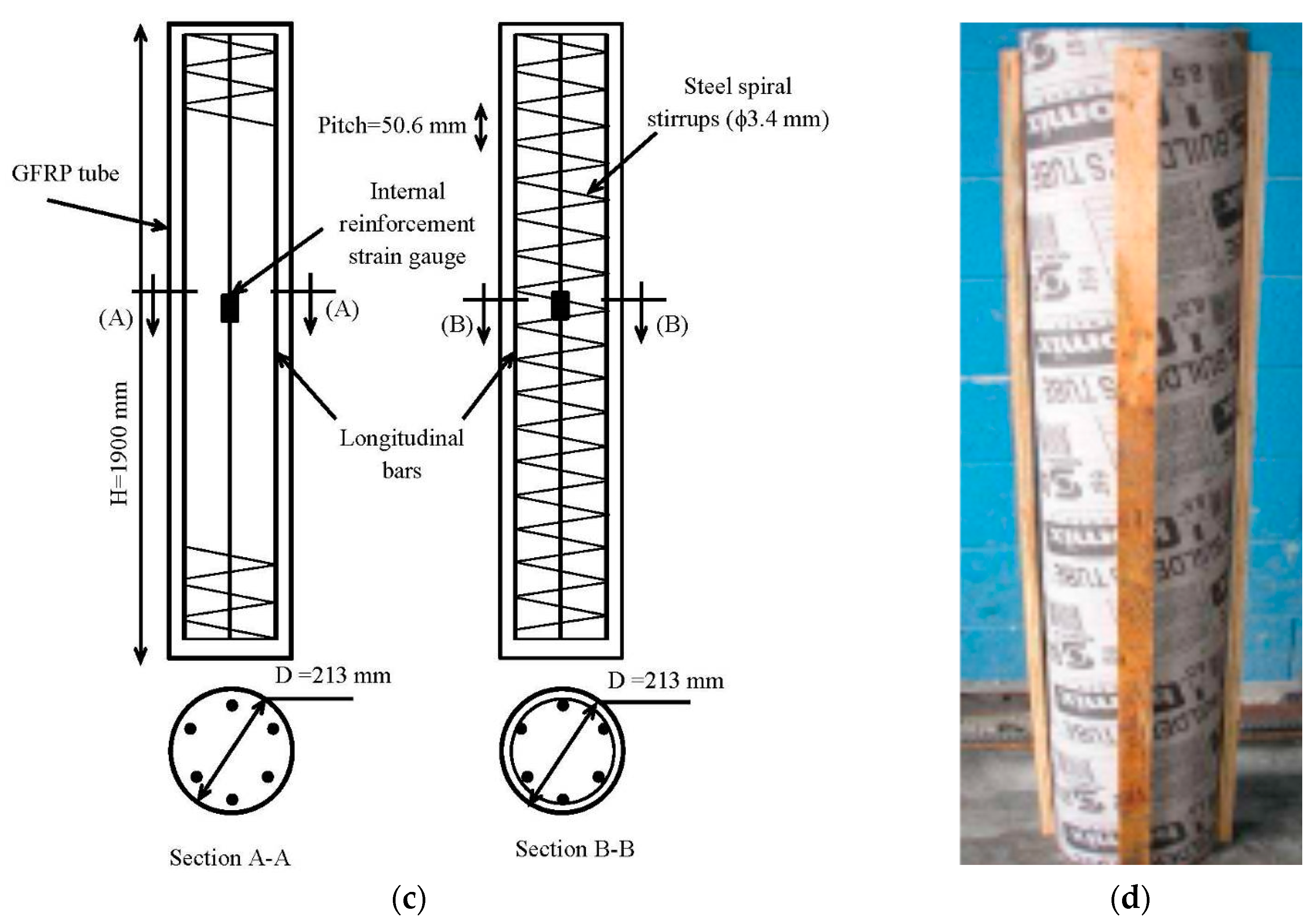
3.1. Test Matrix

A total of 10 RC and CFFT circular columns, comprising 3 RC control columns and 7 steel or FRP-reinforced CFFT columns, were fabricated and tested under concentric axial monotonic or cyclic compression loading. All columns had the same height (h = 1900 mm) to diameter (d = 213 mm) ratio of 9.0. The investigated test parameters were: (i) GFRP tubes thicknesses (2.9 and 6.4 mm); (ii) internal reinforcement type (steel; GFRP; or CFRP bars) and amount; and (iii) natural of loading (i.e., monotonic and cyclic). The control RC columns were reinforced longitudinally with reinforcement ratio (ρL) equal to (3.4%), one specimen reinforced with steel bars and the other specimen reinforced with GFRP bars. Steel spiral stirrups (pitch = 50.6 mm) were used as transverse reinforcement and were designed to have an approximately similar hoop stiffness to the GFRP tube (Type A). The CFFT columns were laterally confined with GFRP tubes (Type A or B). One specimen was internally reinforced with deformed steel bars (6 M15; ρL = 3.4%) and laterally confined with tube type (A). Four specimens were reinforced with six GFRP bars No. 3 or No. 5 (ρL = 1.2 and 3.4%, respectively) and laterally confined with tubes type (A and B). Besides, one specimen (A-C(3.4)-C) was reinforced with longitudinal CFRP bars (6 No. 3; ρL = 1.2%) and laterally confined with tube type (A) and was designed to have similar axial stiffness as in specimen (A-G(3.4)-C). All specimens were tested under single complete unloading/reloading axial cyclic compression loading, except one specimen (B-G(1.2)-M) which was tested under monotonic axial compression loading. Table 2 shows the test specimens’ details. The specimens were labeled as follows: The first letters S, A, or B are defining “the type of lateral reinforcement: steel spiral stirrups, GFRP tube type (A), or tube type (B), respectively”. This was followed by a letter S, G, or C. These letters were used to indicate “the longitudinal reinforcement type: steel, GFRP, or CFRP bars, respectively”, followed by a subscript indicating “the longitudinal reinforcement ratio”. The final letter refers to the nature of loading type “M for monotonic or C for complete unloading/reloading cyclic loading”. For instance, the specimen (A-S(3.4)-C) was laterally confined with GFRP tube type (A), reinforced internally with steel bars with a reinforcement ratio of 3.4%, and tested under cyclic axial compression loading. Table 2 shows the text matrix.

3.2. Material Properties
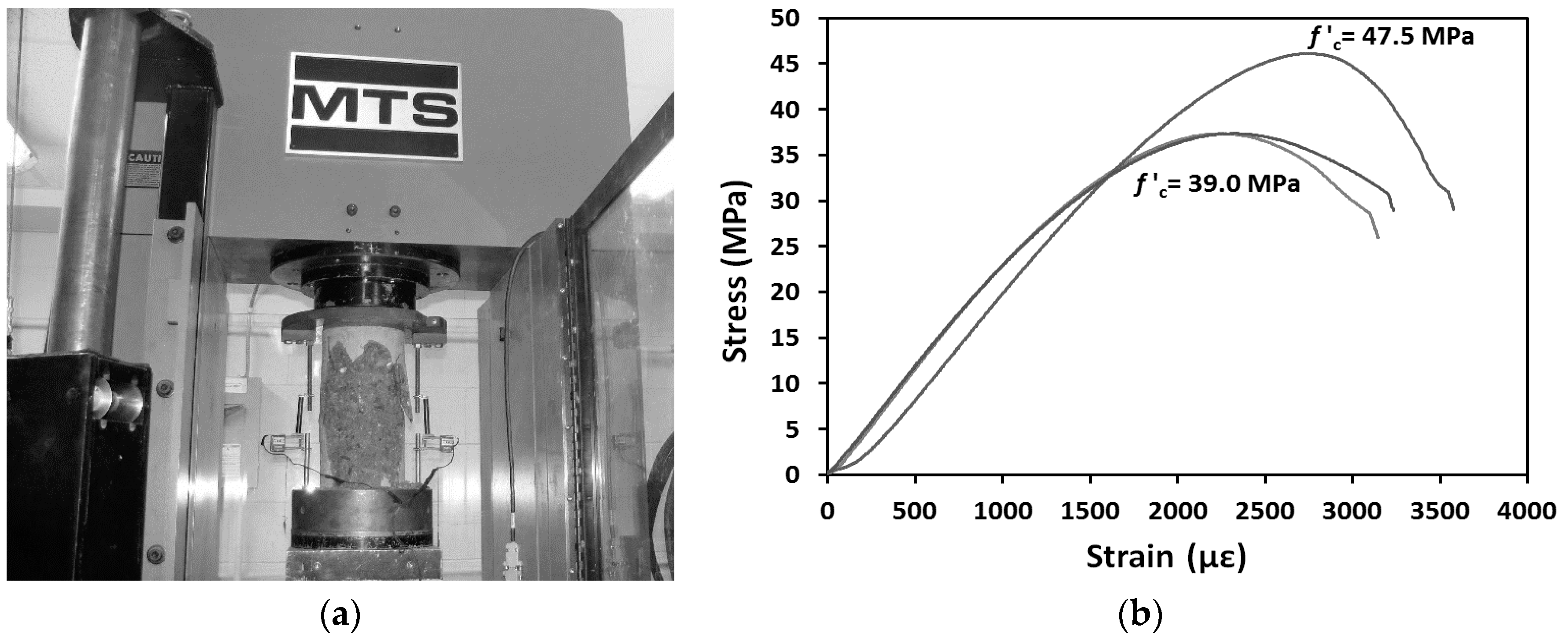
Four materials were used in fabricating the test specimens. These materials are concrete, FRP tubes, steel reinforcing (bars and stirrups), and FRP bars. The following sections provide a description of the different experimental tests conducted to evaluate the mechanical properties of the different materials used herein.

3.2.1. Concrete

All columns were constructed using a ready-mixed normal strength concrete (NSC) with an entrained-air ratio of 5 to 8%. The actual concrete compressive strength was determined from testing six concrete cylinders “150 mm × 300 mm” on the same day of testing the columns. Figure 1 shows typical axial stress-strain curves for the concrete cylinders. The average concrete compressive strength and tensile strength were 41.5 MPa and 4.2 MPa, respectively.

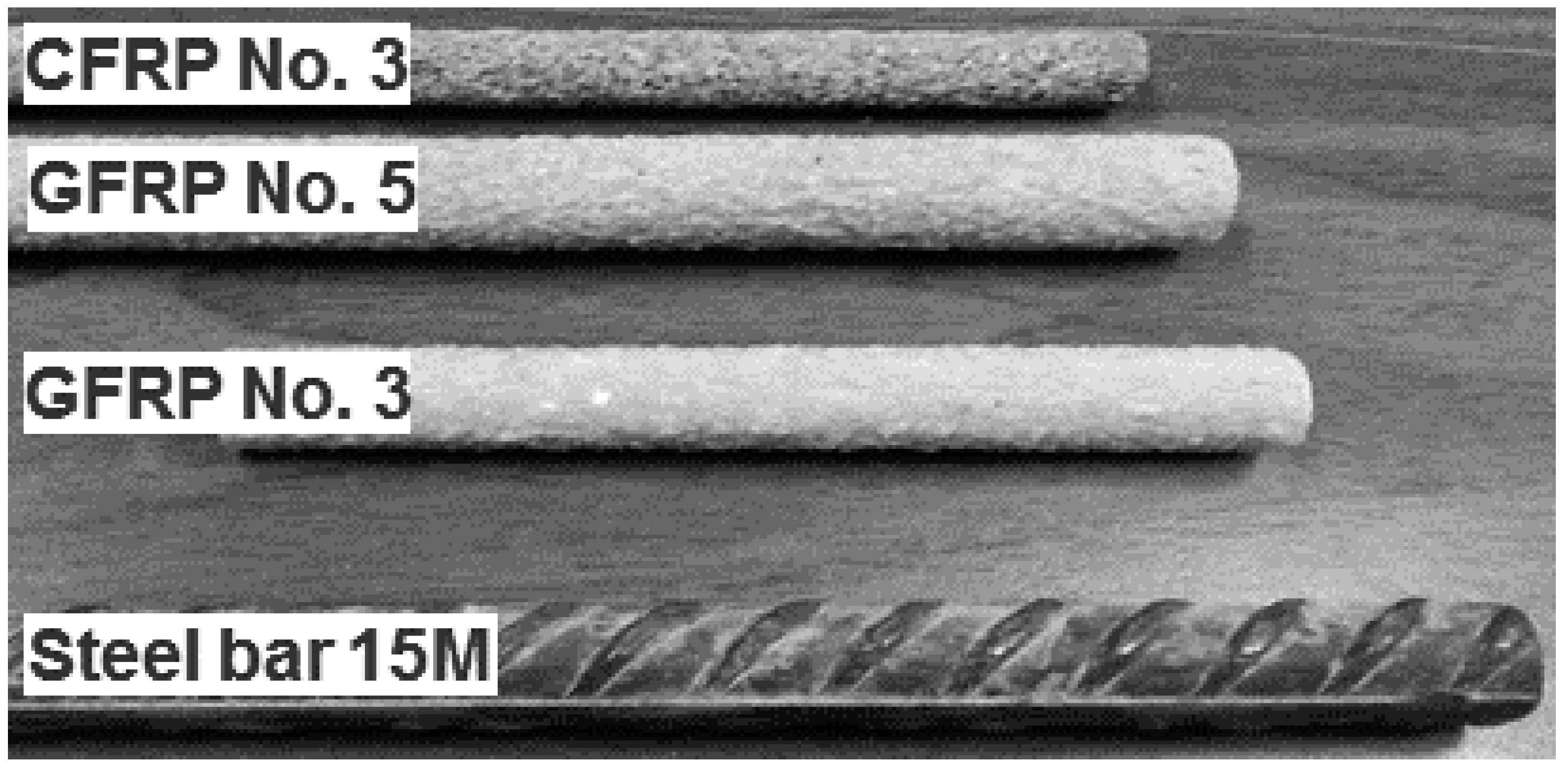
3.2.2. Steel and FRP bars
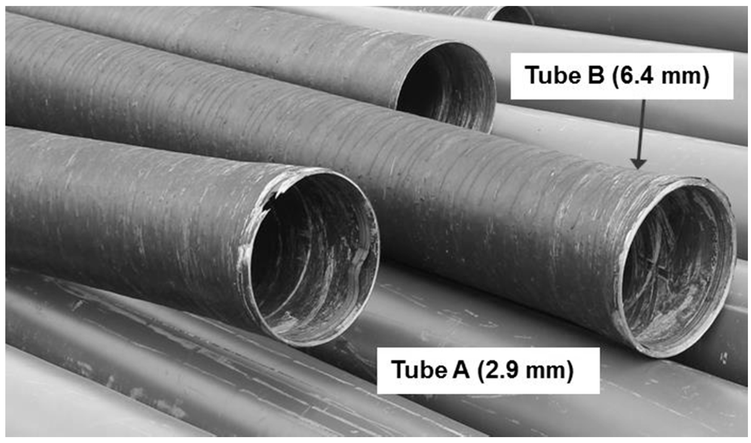
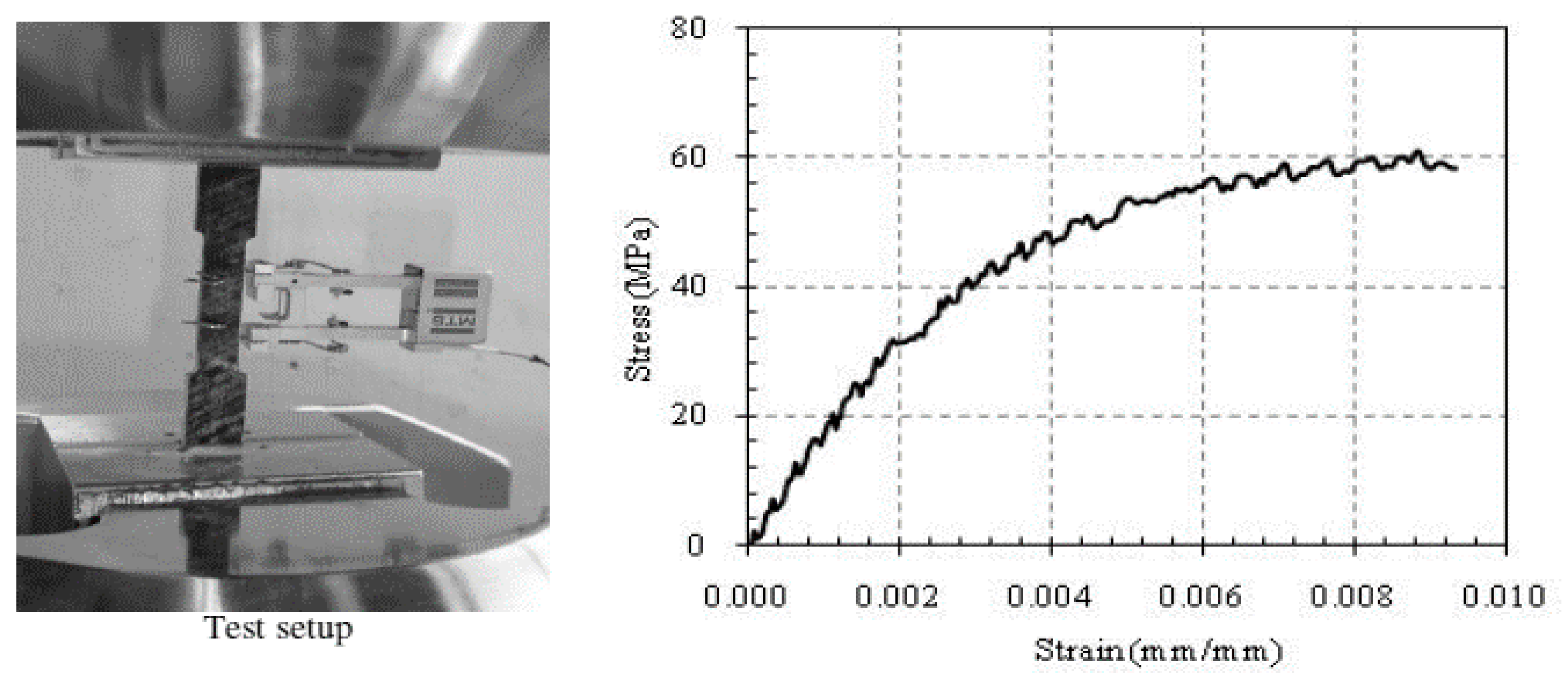
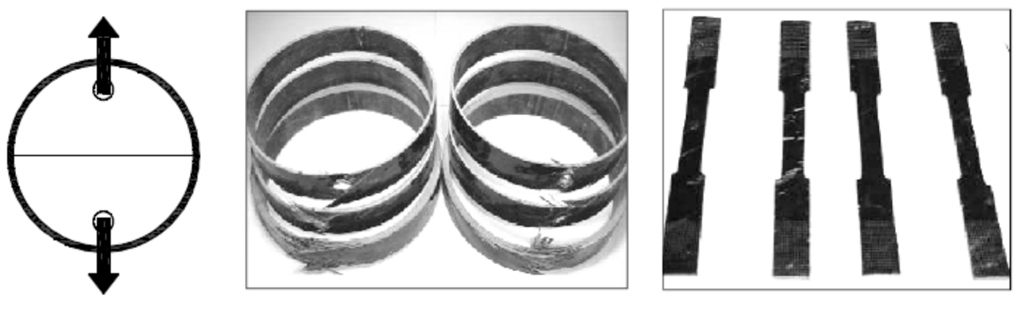
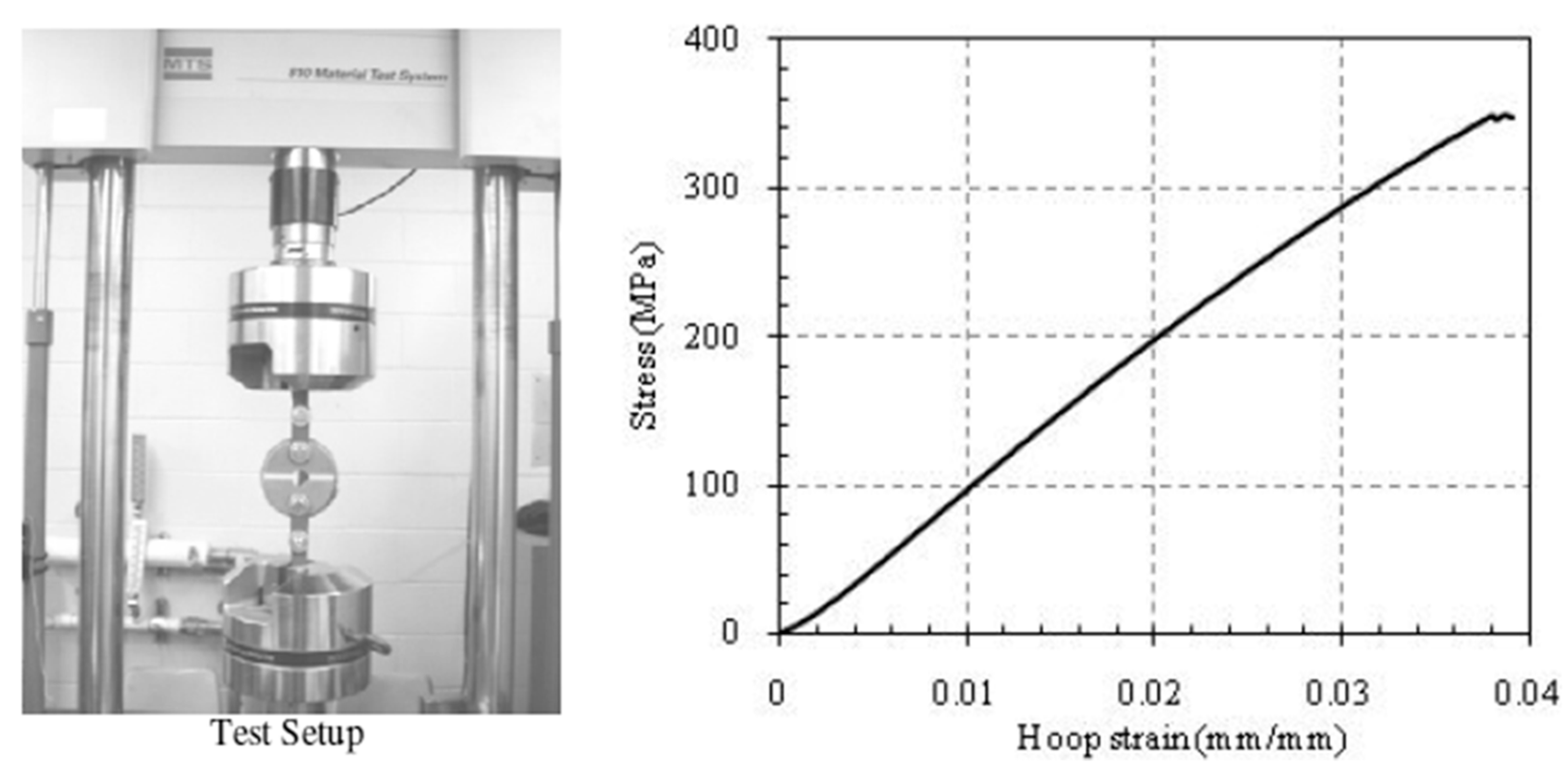
Two different steel bars were used to reinforce the control and CFFT specimens. Wire mild steel bars 3.4 mm in diameter were served as transverse spiral reinforcement for the control specimens. Deformed steel bars M15 (16 mm in-diameter; 200 mm2 in cross-sectional area); were used as a longitudinal reinforcement for test specimens. The mechanical properties of the steel bars were obtained from standard tests that were carried out according to American Society for Testing and Materials (ASTM) [26], on five specimens for each type of steel bar. The mechanical properties of the steel bars are presented in Table 3. Three types of sand-coated FRP bars manufactured by a Canadian company [27] were used as longitudinal reinforcement for the tested columns. Sand-coated surface was made to improve the bond between the bars and surrounding concrete. Two types of FRP bars were made from continuous glass fibres and one type was made from continuous carbon fibres with a fibre content of 73% and impregnated in a vinyl ester resin through the pultrusion process. GFRP bars No. 3 and No. 5 (9.5 mm and 15.9 mm in diameter; 71 mm2 and 199 mm2 in cross-sectional area, respectively) and CFRP bars No. 3 (9.5 mm in diameter; 71 mm2 in cross-sectional area) were used. Table 3 shows the mechanical properties of the FRP bars as provided by the manufacture. Figure 2 shows the different bars used in this investigation.

3.2.3. FRP Tubes

Two types of GFRP tubes were used as structural stay-in-place formwork for the tested specimens. The GFRP tubes were fabricated using a filament-winding technique; E-glass fiber and Epoxy resin with different fibre angles 90° and 60° with respect to the longitudinal axis of the tubes. The two types of GFRP tubes (types A&B) were used with different thicknesses and having the same internal diameters 213 mm as shown in Figure 3. The thickness of tube (A) equals 2.90 mm, while for tube B equals 6.40 mm. The glass fibre volume fraction as provided by the manufacture was 68 ± 3%. Figure 4 shows the specimens of FRP tubes for the split-disk test and coupon tensile test. Typical test samples of the coupon tests and split-disk test in the axial and hoop directions for GFRP tubes are shown in Figure 5 and Figure 6, respectively. Table 4 shows the dimensions and mechanical properties of FRP tubes.

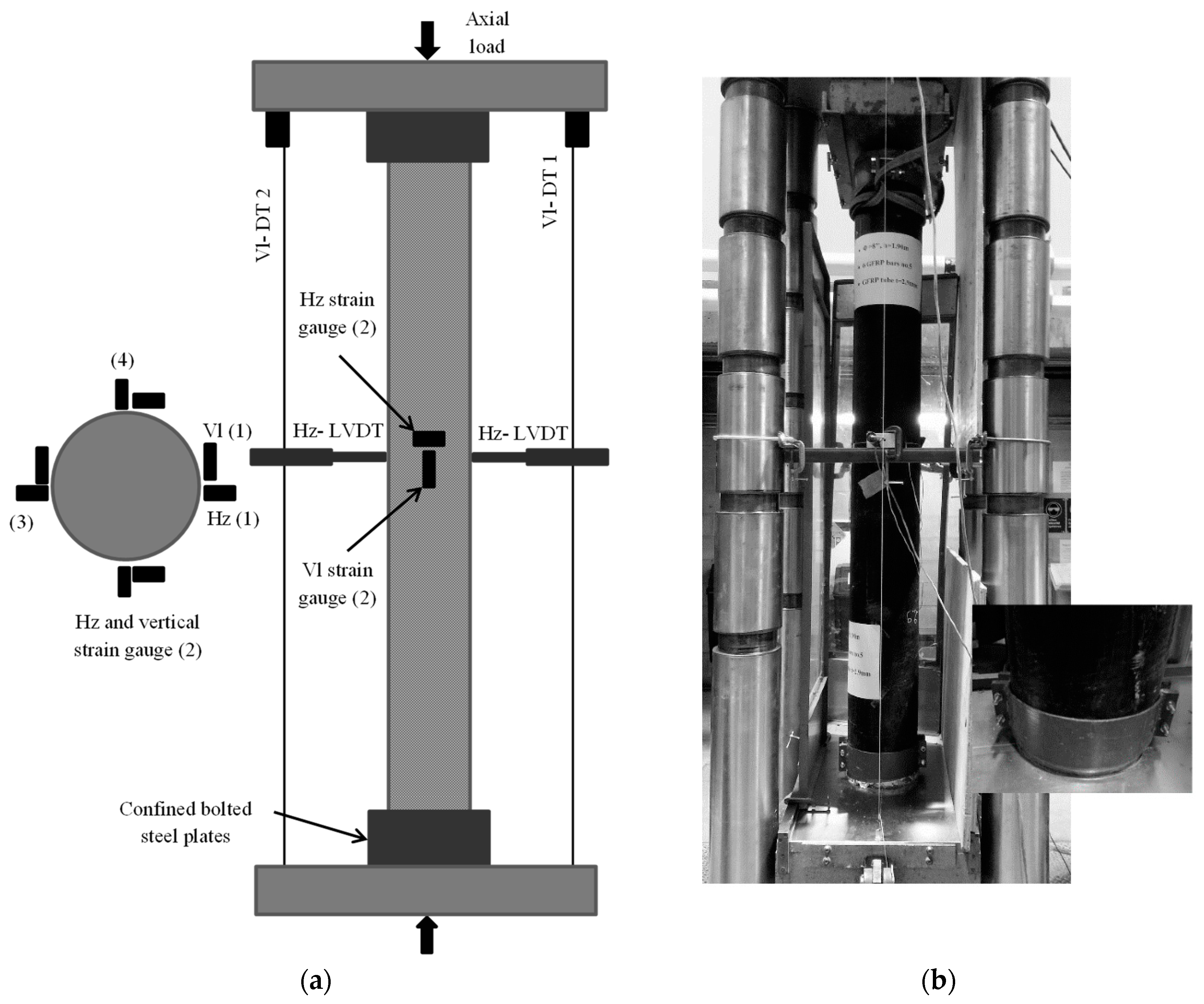
3.3. Instrumentation and Testing Procedures

Several strain gauges were mounted on the internal reinforcement bars prior to the concrete casting and on concrete or GFRP tube surfaces before testing. Eight strain gauges were located at the column mid-height in both axial and lateral directions to measure the axial and lateral strains, respectively. Two strain gauges were bonded on two longitudinal bars 180° degree apart at the mid-height of the column. Two displacement transducers (DTs) were used to measure the axial deformation of the column over the full height as shown in Figure 7a. Additionally, two in-plane linear variable displacement transducers (LVDTs) were located at the mid-height to record the lateral displacements of each column.
All columns were capped with a thin layer of the high strength sulphur to ensure uniform load distribution during testing. Before testing, both ends of the columns were further confined with bolted steel collars made from 10 mm (0.39 in) thick steel plates in order to prevent premature failure at their ends. The specimens were loaded under axial compression loading using a 6000-kN (1349 kips) capacity-testing machine. Loading and unloading in compression tests were achieved with load control at a rate approximately equal to 2.3 kN/s and each cyclic 40 kN until failure. During the test, load, axial and lateral displacements, and strains were recorded automatically using a data acquisition system connected to the computer. Figure 7 shows the test specimen schematic and the test specimen inside the testing machine.

4. Test Result and Discussion

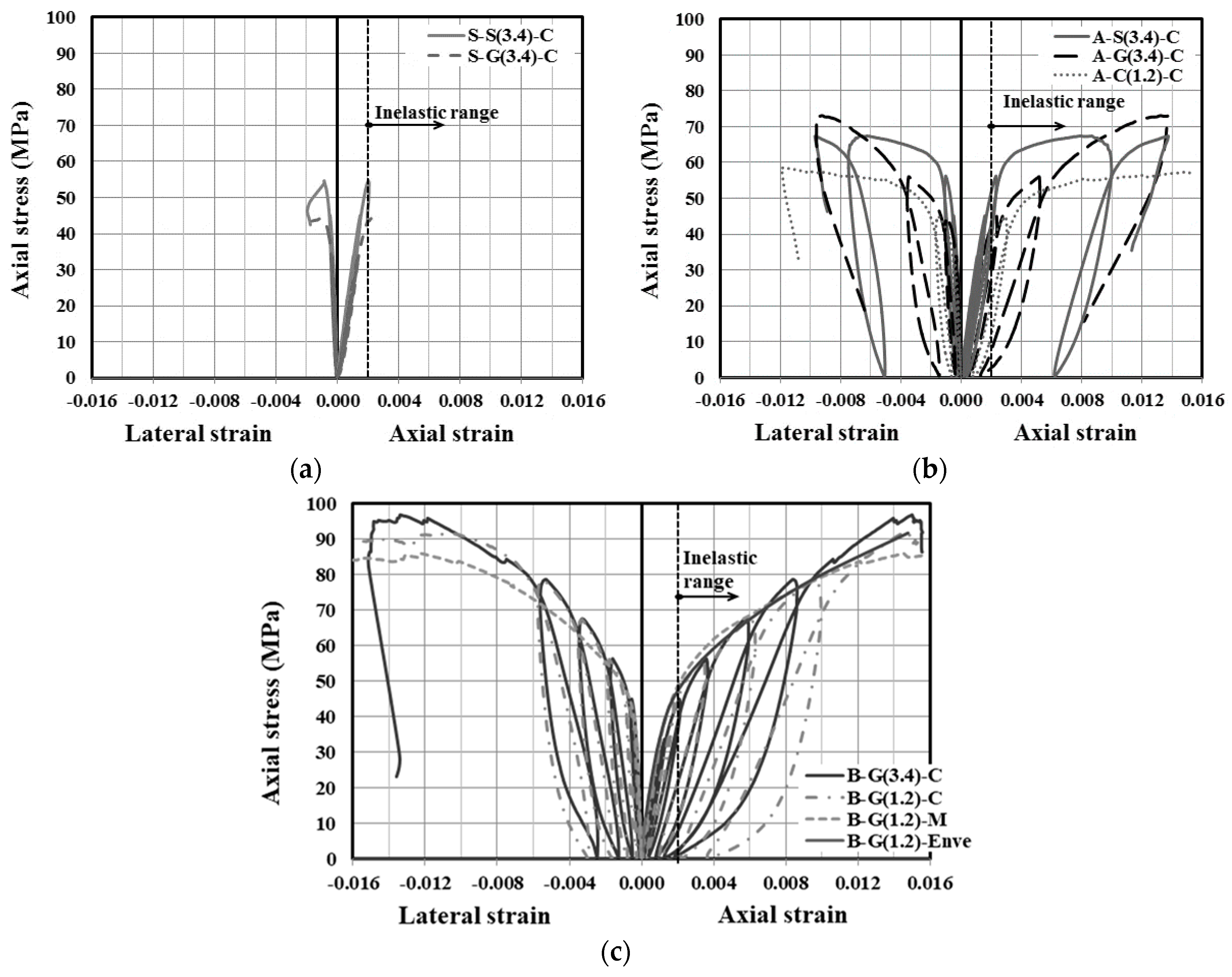
4.1. Axial and Lateral Stress-Strain Responses

Figure 8 depicts the cyclic and monotonic stress-strain relationships for reinforced control and CFFT columns. In Figure 8, the axial stress and strain are presented as positive and the lateral strain as negative. The axial stress was obtained from dividing the axial load by the concrete gross area (Ag). The axial and lateral stress-strain curves were plotted from the maximum recorded strain gauge of each column bonded in the vertical and hoop directions at the column mid-height. The key experimental results of the tested columns are shown in Table 2. In this Table 2, the experimental ultimate load (Pu), the confined concrete compressive strength ( f cc )—that is, the maximum compressive strength at the ultimate load (=Pu/Ag), the corresponding axial strain ( ε cc ), the unconfined concrete compressive strength ( f c ) from cylinders and the corresponding axial strain of unconfined concrete ( ε co ) are reported. As shown in Figure 8, the stress-strain diagrams for all columns exhibited almost similar initial stiffness with a relatively linear slope in the elastic range of the stress-strain curves, indicating that the elastic axial stiffness is not affected by confinement, regardless of the investigated tested parameters. Lam and Teng [12] and Karimi [29] also noted that in the elastic range when axial strain values were smaller than 0.002, the confinement of FRP-confined concrete is negligible. As seen in Figure 8, in all reinforced CFFT columns the maximum compressive strain at failure exceeded the elastic axial strain limit (taken as 0.002) indicating inelastic overall buckling of the reinforced CFFT columns [29]. On the other hand, the stress-strain responses of the GFRP-reinforced control columns initially behaved similar to that of the steel-reinforced control column up to their peak load. However, the peak axial stress for the steel-reinforced column was slightly higher than that of their counterpart reinforced with GFRP bars by an average of 11%.
The enveloped curves of the reinforced CFFT columns represent the upper boundary of the cyclic axial stress-strain responses, showing bilinear responses with a transition zone in the vicinity of the unconfined concrete ( f c ), followed by near stabilization of the load-carrying capacity at the end due to excessive lateral buckling until failure (i.e., B-G(3.4)-C and B-G(1.2)-C). The initial slope was almost identical for all the specimens while the second slope is highly governed by GFRP tubes stiffness rather than the internal reinforcement type and amount, particularly in thicker tube thickness (see Figure 4). The axial stress-strain curves for GFRP and steel-reinforced CFFT columns showed similar shapes of the hysteresis loops for the unloading/reloading paths. However, the steel-reinforced CFFT column hysteresis loop starts to open after the yielding of steel bars. The unloading paths for the CFFT columns reinforced with steel or FRP bars exhibited non-linear behavior. The degree of the non-linearity increased as the unloading axial strain increased. Moreover, the reloading paths could be resembled as straight lines. It can be also observed that the FRP-reinforced CFFT columns exhibited lower residual plastic strains compared to that of the steel-reinforced CFFT columns after the yielding of the steel bars, when the load was removed. This is due to the lack of yield plateau in GFRP bars which results in a much lower residual strains. In addition, due to the fact that the steel bars have a very low tangent modulus after yielding and, therefore, are more susceptible to buckling under compression than GFRP bars which maintain their modulus of elasticity throughout the entire duration of loading [12,30,31,32].

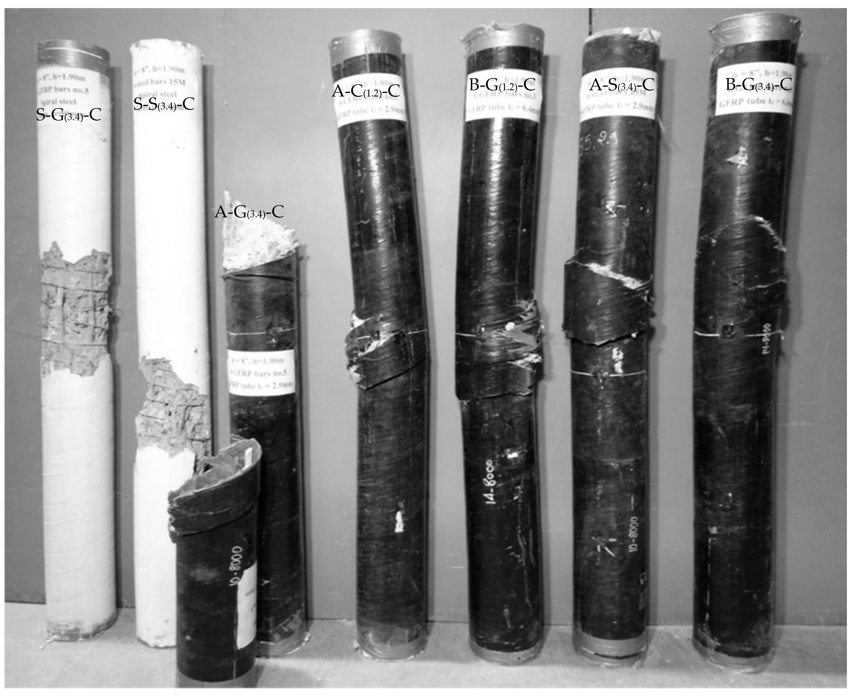
4.2. Mode of Failure

The GFRP tube provided significant confinement attributing to shift the failure mode from axially dominated material failure to instability failure for the CFFT columns. The instability was evident in a significant single curvature mode shape of the bent column. Despite the specimens experiencing large lateral deflections beyond the ultimate load, the deflected columns were still stable and carried more axial load. Loading the specimens continued until localized failure occurred near the mid height of the column. Finally, GFRP tube rupture, concrete crushing, and local buckling of steel bars or crushing of the FRP bars in the compression side of the CFFT columns were observed. This observation is in agreement with the previous research works conducted on slender FRP-confined columns [3,33]. On the other hand, the control columns showed a substantially different failure mode compared to that which occurred for the CFFT columns. For both control columns reinforced with steel or GFRP bars showed similar responses. The failure was typically initiated with vertical cracks starting to appear at approximately 85% of their peak loads and followed by concrete dilation and lateral deformation of transverse and longitudinal reinforcement leading to concrete cover spalling. Thereafter, the concrete core crushed and spiral stirrups fractured after the buckling of the longitudinal bars. Moreover, inclined diagonal shear surface was observed leading to a separation of the concrete core into two column parts causing a sudden drop after reaching the peak load. Figure 9 shows overall failure modes of tested specimens. Table 2 summarizes the test results for all specimens.

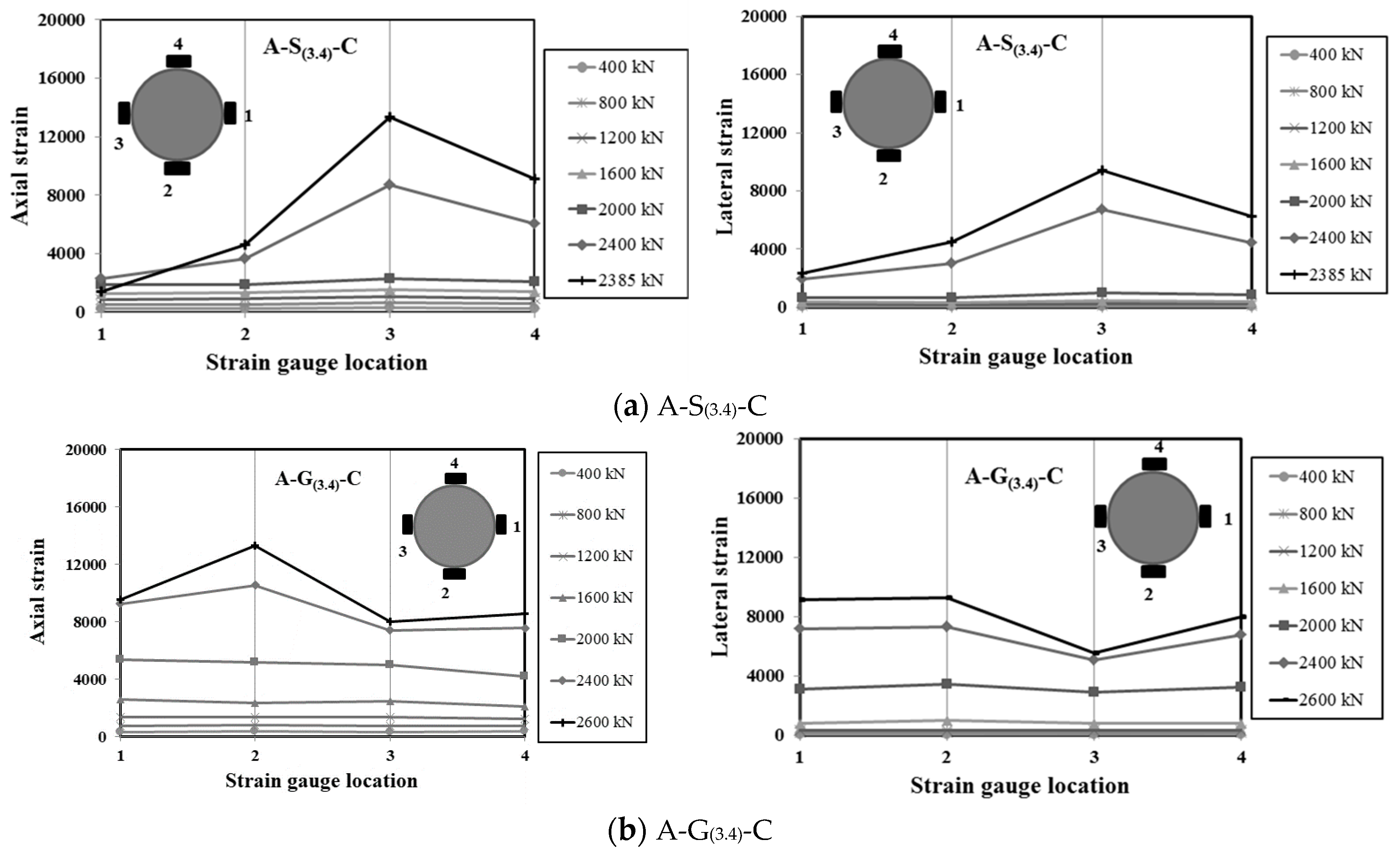
4.3. State of Stress in the GFRP Tube

Typical distributions of axial and lateral strains at various loads of selected reinforced CFFT columns over the perimeter of the GFRP tube at the column mid-height are presented in Figure 10. As shown in this figure, the uniform distribution of the lateral strains in the FRP tubes near loading level of 2000 kN (450 kips) indicates efficient confinement of the tubes. As a result of the instability failure of the reinforced CFFT columns, due to buckling produced by highly variable lateral confinement and induced significant bending in the column before failure. The maximum, minimum, and average lateral strains in the hoop direction (εh, max, min, aver.) of the FRP tube at the ultimate load are reported in Table 2.

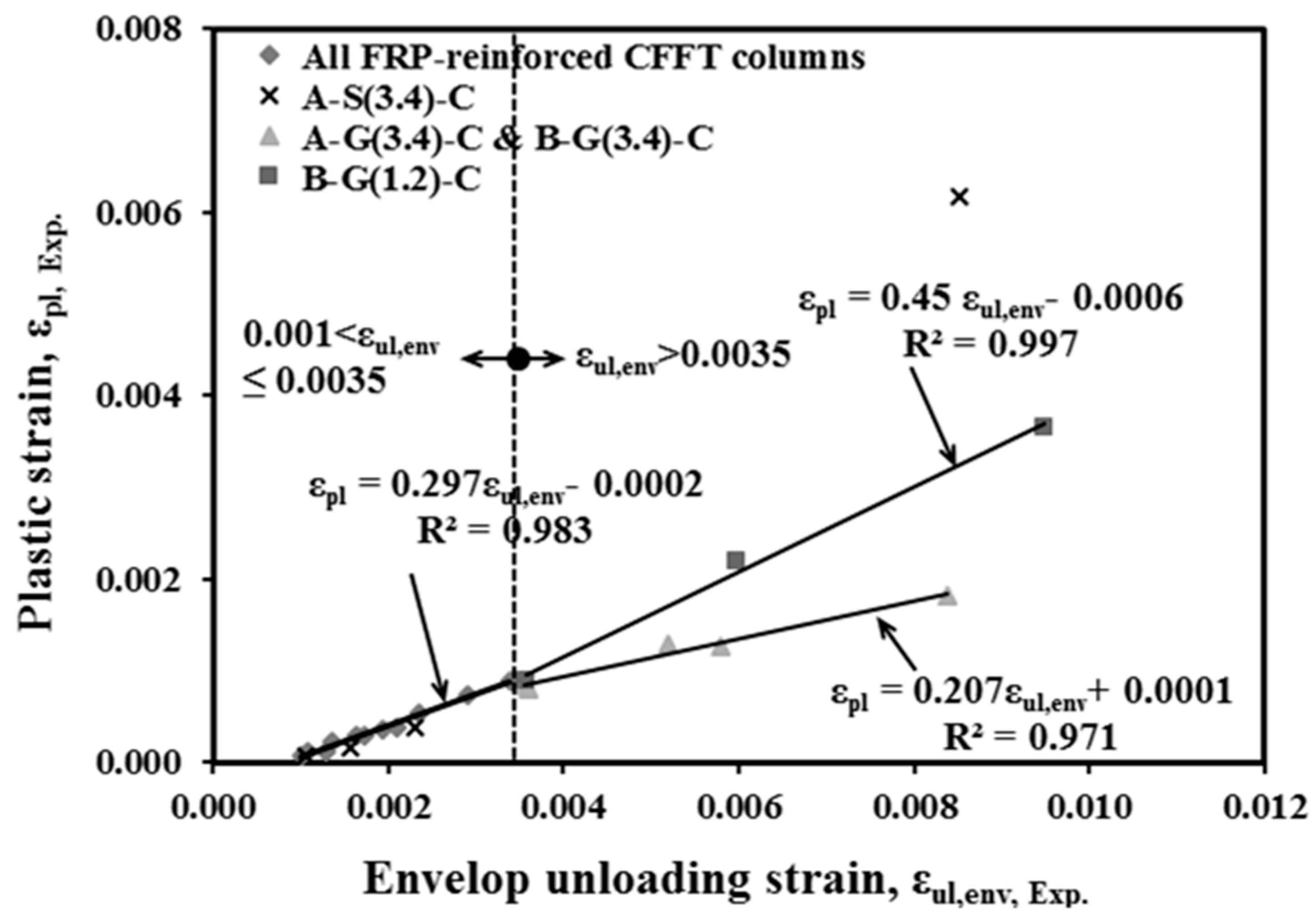
4.4. Plastic Strains

The relationship between the plastic strain and envelop unloading strain (εun,env.) is an important aspect for modelling the unloading/reloading axial cycles. The plastic strain (εpl) in this paper is defined as the residual axial strain when the axial stress is unloaded to zero stress of each unloading path [12,34]. Previous studies for unconfined, steel-confined, and FRP-confined concrete cylinders and square prisms (e.g., [9,12,30,31,34]) have shown that the plastic strain is linearly proportional to envelop unloading strain. Yet, the proposed model of Lam and Teng [12] is highly accurate in predicating both the unloading and reloading paths and estimate plastic strains for FRP-confined NSC cylinders [25]. Lam and Teng [12] suggested the following equations to predicate the plastic strains: (1) εpl = 0 when εun,env ≤ 0.001; (2) a linear increase in εpl when 0.001 ≤ εun,env ≤ 0.0035 (Equations (3) and (5) an additional linear increase relationship when εun,env > 0.0035 (Equation (3)). In the present study, in order to evaluate the effect of confinement level and internal reinforcement type and ratio on the plastic strains, the correlations between the plastic strain versus unloading envelope strains of specimens in each cycle, are plotted in Figure 11.
ε pl = [ 1.4 ( 0.87 0.004 f c ) 0.64 ]   ( ε un , env 0.001 )
ε pl = ( 0.87 0.004 f c )   ε un , env 0.0016
In Figure 11, it can be observed that the plastic strains of the reinforced CFFT columns when εun,env < 0.001 are negligible. The trend line at the unloading envelope strain ranged between 0.001 and 0.0035 and almost coincide, which suggests that the residual plastic strain has little or no influence on the reinforced CFFT specimens, regardless of the investigated test parameters. Also, a linear relationship between the plastic strains and envelope unloading strain is observed. This observation is also in good agreement with previous tests conducted on FRP-confined unreinforced concrete cylinders and steel-reinforced square prisms [8,12,31,34]. Nevertheless, when the envelope unloading strains were above 0.0035 (εun,env > 0.0035), it was found that the plastic strains of the FRP-reinforced CFFT columns were linearly proportional to the envelop unloading strains. The relationship is slightly dependent on the level of confinement but is strongly dependent on the longitudinal reinforcement amount and type. The statistical characteristics of the trend lines for reinforced CFFT columns showed different trends. The slope of the trend lines of the CFFT columns reinforced with GFRP bars decrease linearly with the increase of the FRP longitudinal reinforcement ratio.

5. Comparisons of Predictions versus Experimental Results

This section evaluates the applicability of the confinement models of the Canadian codes and the ACI design codes and guidelines to the tested columns, and identifies the most and least conservative model’s predictions. Table 5, Table 6 and Table 7 present the predicated axial load-carrying capacity versus the experimental test results for the control and CFFT-reinforced specimens as specified by the North American codes for steel and FRP bars, respectively. The safety and environmental reductions factors included in all the design equations were set to 1.0. Several limitations were also considered to control the ( f cc ) predications as recommended by the design codes and guidelines, for instance the CAN/CSA-S806 [25] limits the FRP hoop strain to 0.006 times its elastic modulus Ef while the CAN/CSA-S6-06 [21] limits the confinement pressure flFRP at the ultimate limit state (ULS) to be between 0.1 f c and 0.33 f c . Furthermore, the ACI 440.2R (2008) [1] limits the maximum ultimate strain to 0.01 to prevent excessive cracking and the resulting loss of concrete integrity. When this limit is applicable, the corresponding maximum value of ( f cc ) should be recalculated from the stress-strain curve. The confining pressure, flFRP, was calculated based on the ultimate hoop tensile strength fFRPu, which equals the value obtained from the split disk test.
For the GFRP-reinforced control specimens, the ACI 440.1R [24], CSA S806 [25], and CSA S6-06 [21] predication values were an average (Ptest/Ppred) of 1.45 ± 0.02, 1.57 ± 0.02, and 1.67 ± 0.02 and COVs of 1.38%, respectively. The ACI 440.1R [24] had the closest predication values to the experimental results. However, all codes showed slightly higher conservative predication values for the GFRP-reinforced control specimens than for the steel-reinforced column. This might be due to neglecting the contribution of the compressive resistance of the GFRP bars to the axial-carrying capacity. Tobbi et al. [20] and Afifi el al. [16] reported that the compressive strength of the GFRP bars could be taken as a function of its tensile strength. Therefore, they introduced a new factor equal to 0.35 of the tensile strength to account for the reduction in the compressive strength of the GFRP bars.
Generally speaking, all design codes and guidelines overestimated the values for the FRP-reinforced CFFT columns, particularly those specimens with tube Type B. The ACI 440.2R [3], CSA S806 [9], and CSA S6-06 [10] predication values were 1.68 ± 0.31, 1.57 ± 0.18, and 1.72 ± 0.35 and had a COV of 18.4%, 11.3%, and 20.5%, respectively. As shown in Table 6, the CSA S806 [25] predications were better based on the average than the ones of the CSA S6-06 [21] and ACI 440.2R [1]. It should be mentioned that the ( f cc ) provided by CSA S806 [25] is governed by limiting the hoop tensile strain to be not more than 0.006. In addition, limiting the confinement pressure flFRP ≤ (0.33 f c ) according to the CSAS6-06 [21] and the maximum ultimate strain equal to 0.01, according to the ACI 440.2R [1], for the specimens with tube Type B, also led to more conservative predictions. However, with no consideration for the confinement codes limits, the CSA S806 [25] predication values underestimated while the CSA S6-06 [21] and ACI 440.2R [1] yielded good yet conservative predication values. In order to better predict and model the stress-strain behavior of CFFT columns internally reinforced with FRP and steel bars subjected to axial cyclic compression loading further experimental investigations are needed.

6. Conclusions

On the basis of the experimental test results and theoretical investigations in this paper, the following conclusions can be drawn:
  • As expected, an increase in the FRP tube thickness (or stiffness) results in an increase in the strength and strain enhancement ratios ( f cc / f c and εcc/εco).
  • In general, the envelop curves for the CFFT tested specimens showed bilinear responses with a transition zone near the peak strength of the unconfined concrete ( f c ). The slope of the second branch is highly governed by GFRP tube stiffness rather than the longitudinal reinforcement amount and type.
  • The FRP-reinforced CFFT columns showed lower residual plastic strains compared to that of the steel-reinforced CFFT columns after the yielding of the steel bars, when the load was removed. This can be due to the lack of yield plateau in GFRP bars which results in a much lower residual strain. As a result, the influence of internal reinforcement on cyclic loading should be considered when modelling the unloading/reloading cyclic axial stress-strain response.
  • The GFRP-reinforced CFFT columns showed comparable ultimate axial strength and strain capacities compared to their counterparts reinforced with steel bars. This proves the applicability of exclusively reinforcing the CFFT columns with FRP bars and subjecting them to an axial compression load. However, a wide range of investigated parameters are necessary for a complete understanding of the behavior of FRP-reinforced CFFT columns.
  • The ACI 440.R1 (2015), CSA S806 (2012), and CSA S6-06 (2010) design provisions provided higher conservative results for the GFRP-reinforced control specimens than that of the steel-reinforced specimen. This might be due to neglecting the contribution of the compressive resistance of the GFRP bars to the axial-carrying capacity.
  • For FRP-reinforced CFFT columns, the CSA S806 (2012) showed better predictions based on the average with and without considering the confinement codes limits than that of the CSA S6-06 (2010) and ACI 440.2R (2008), particularly for thicker tube thickness.

Author Contributions

Conceptualization, Methodology, Validation, Formal Analysis, Investigation, Writing—Original Draft Preparation, and Writing—Review & Editing, A.A.A.; Supervision, and Funding Acquisition, R.M.

Funding

This research was partially funded by [Natural Sciences and Engineering Research Council of Canada (NSERC)].

Acknowledgments

The authors acknowledge the contribution of the Canadian Foundation for Innovation (CFI) for the infrastructure used to conduct testing. Special thanks to the manufacturer (FRE Composites, QC, Canada) for providing FRP tubes.

Conflicts of Interest

The authors declare no conflicts of interest.

References

  1. American Concrete Institute (ACI). Guide for the Design and Construction of Externally Bonded FRP Systems for Strengthening Concrete Structures; ACI 440.2R-08; American Concrete Institute: Farmington Hills, MI, USA, 2008. [Google Scholar]
  2. Fam, A.Z.; Rizkalla, S. Behavior of axially loaded concrete-filled circular fiber reinforced polymer tubes. ACI Struct. J. 2001, 98, 280–289. [Google Scholar]
  3. Fitzwilliam, J.; Bisby, L. Slenderness Effects on Circular CFRP Confined Reinforced Concrete Columns. J. Compos. Constr. 2010, 14, 280–288. [Google Scholar] [CrossRef]
  4. Lam, L.; Teng, J.G. Design-oriented stress-strain models for FRP-confined concrete. Constr. Build. Mater. 2003, 17, 471–489. [Google Scholar] [CrossRef]
  5. Samaan, M.; Mirmiran, A.; Shahawy, M. Modeling of concrete confined by fiber composites. J. Struct. Eng. 1998, 124, 1025–1031. [Google Scholar] [CrossRef]
  6. Wei, Y.Y.; Wu, Y.F. Unified stress–strain model of concrete for FRP-confined columns. Constr. Build. Mater. 2012, 26, 381–392. [Google Scholar] [CrossRef]
  7. Xiao, Y.; Wu, H. Compressive behavior of concrete confined by carbon fiber composite jackets. J. Mater. Civ. Eng. 2000, 12, 139–146. [Google Scholar] [CrossRef]
  8. Abbasnia, R.; Ahmadi, R.; Ziaadiny, H. Effect of confinement level, aspect ratio and concrete strength on the cyclic stress–strain behavior of FRP-confined concrete prisms. Compos. Part B Eng. 2012, 43, 825–831. [Google Scholar] [CrossRef]
  9. Abbasnia, R.; Hosseinpour, F.; Rostamian, M.; Ziaadiny, H. Cyclic and monotonic behavior of FRP confined concrete rectangular prisms with different aspect ratios. Constr. Build. Mater. 2013, 40, 118–125. [Google Scholar] [CrossRef]
  10. Ilki, A.; Kumbasar, N. Compressive behavior of carbon fiber composite jacketed concrete with circular and non-circular cross sections. J. Earthq. Eng. 2003, 7, 381–406. [Google Scholar] [CrossRef]
  11. Lam, L.; Teng, J.G.; Cheung, J.G.; Xiao, Y. FRP-confined concrete under axial cyclic compression. Cem. Concr. Compos. 2006, 28, 949–958. [Google Scholar] [CrossRef]
  12. Lam, L.; Teng, J.G. Stress-strain model for FRP-confined concrete under cyclic axial compression. Eng. Struct. 2009, 31, 308–321. [Google Scholar] [CrossRef]
  13. Mirmiran, A.; Shahawy, M.; Beitleman, T. Slenderness Limit for Hybrid FRP Concrete Columns. J. Compos. Constr. 2001, 5, 26–34. [Google Scholar] [CrossRef]
  14. Ozbakkaloglu, T.; Lim, J.; Vincent, T. FRP-confined concrete in circular sections: Review and assessment of stress–strain models. Eng. Struct. 2013, 49, 1068–1088. [Google Scholar] [CrossRef]
  15. Shao, Y.; Zhu, Z.; Mirmiran, A. Cyclic modeling of FRP confined concrete with improved ductility. Cem. Concr. Compos. 2006, 28, 959–968. [Google Scholar] [CrossRef]
  16. Afifi, Z.; Mohamed, M.; Benmokrane, B. Axial capacity of circular concrete columns reinforced with glass-FRP bars and spirals. J. Compos. Constr. 2014, 18, 04013017. [Google Scholar] [CrossRef]
  17. De Luca, A.; Matta, F.; Nanni, A. Behavior of full-scale glass fiber-reinforced polymer reinforced concrete columns under axial load. ACI Struct. J. 2010, 107, 589–596. [Google Scholar]
  18. Mohamed, H.; Afifi, M.; Benmokrane, B. Performance Evaluation of Concrete Columns Reinforced Longitudinally with FRP Bars and Confined with FRP Hoops and Spirals under Axial Load. J. Bridge Eng. 2014, 19, 04014020. [Google Scholar] [CrossRef]
  19. Sharma, U.K.; Bhargava, P.; Kaushik, S.K. Behavior of confined high strength concrete columns under axial compression. J. Adv. Concr. Technol. 2005, 3, 267–281. [Google Scholar] [CrossRef]
  20. Tobbi, H.; Farghaly, A.S.; Benmokrane, B. Concrete columns reinforced longitudinally and transversally with glass fiber-reinforced polymers bars. ACI Struct. J. 2012, 109, 1–8. [Google Scholar]
  21. Canadian Standard Association (CSA). Canadian Highway Bridge Design Cod; CAN/CSA-S6-06; Canadian Standard Association: Toronto, ON, Canada, 2010. [Google Scholar]
  22. Canadian Standards Association (CAN/CSA). Design of Concrete Structures; A23.3-14; Canadian Standards Association: Mississauga, ON, Canada, 2014. [Google Scholar]
  23. American Concrete Institute (ACI). Building Code Requirements for Structural Concrete; ACI 318-14; American Concrete Institute: Farmington Hills, MI, USA, 2014. [Google Scholar]
  24. American Concrete Institute (ACI). Guide for the Design and Construction of Concrete Reinforced with FRP Bars; ACI 440.1R-15; American Concrete Institute: Farmington Hills, MI, USA, 2015. [Google Scholar]
  25. Canadian Standard Association (CSA). Design and Construction of Building Components with Fibre-Reinforced Polymers; CSA-S806-12; Canadian Standards Association: Toronto, ON, Canada, 2012. [Google Scholar]
  26. ASTM A615/A615M-09. Standard Specification for Deformed and Plain Carbon Steel Bars for Concrete Reinforcement; ASTM: West Conshohocken, PA, USA, 2009. [Google Scholar]
  27. Pultrall, Inc. V-ROD Composite Reinforcing Rods Technical Data Sheet; Pultrall, Inc.: Thetford Mines, QC, Canada, 2007; Available online: www.pultrall.com (accessed on 15 July 2007).
  28. Masmoudi, R.; Mohamed, H. Axial behavior of slender-concrete-filled FRP tube columns reinforced with steel and carbon FRP bars. In Proceedings of the 10th International Symposium on Fiber-Reinforced Polymer Reinforcement for Concrete Structures, Tampa, FL, USA, 2–4 April 2011. [Google Scholar]
  29. Karimi, K.; Tait, M.; El-Dakhahkni, W. Influence of Slenderness on the behavior of a FRP-Enclosed Steel-Concrete Composite Column. J. Compos. Constr. 2012, 16, 100–109. [Google Scholar] [CrossRef]
  30. Ozbakkaloglu, T.; Akin, E. Behavior of FRP-confined normal- and high-strength concrete under cyclic axial compression. J. Compos. Constr. 2012, 16, 451–463. [Google Scholar] [CrossRef]
  31. Sakai, J.; Kawashima, K. Unloading and reloading stress strain model for confined concrete. J. Struct. Eng. 2006, 132, 112–122. [Google Scholar] [CrossRef]
  32. Xia, Y.; Xian, G.; Wang, Z.; Li, H. Static and Cyclic Compressive Properties of Self-Compacting Concrete-Filled Flax Fiber–Reinforced Polymer Tubes. J. Compos. Constr. 2016, 20, 04016046. [Google Scholar] [CrossRef]
  33. Mohamed, H.; Abdel Baky, H.; Masmoudi, R. Nonlinear stability analysis of CFFT columns: Experimental and Theoretical Investigations. ACI Struct. J. 2010, 107, 699–708. [Google Scholar]
  34. Wang, Z.; Wang, D.; Smith, S.; Lu, D. CFRP-Confined Square RC Columns. II: Experimental Investigation. J. Compos. Constr. 2012, 16, 150–160. [Google Scholar] [CrossRef]
Figure 1. (a) Compression test of concrete cylinders; (b) typical axial stress-strain relationships for concrete cylinders.
Jcs 02 00057 g001
Figure 2. Different steel and fiber-reinforced polymer (FRP) bars used in this study.
Jcs 02 00057 g002
Figure 3. Filament wound glass fiber-reinforced polymer (GFRP) tubes.
Jcs 02 00057 g003
Figure 4. Specimens of FRP tubes for the split-disk test and coupon tensile test [28].
Jcs 02 00057 g004
Figure 5. Test setup and stress-strain curve for the FRP tubes for coupon tensile test of Tube B [28].
Jcs 02 00057 g005
Figure 6. Test setup and stress-hoop strain behavior of the FRP tubes for split-disk test of Tube B [28].
Jcs 02 00057 g006
Figure 7. Instrumentations and test setup: (a) schematic of the test setup and placing of specimen instrumentations; (b) test specimen inside the testing machine; (c) test specimens details A-A for concrete-filled, fiber-reinforced polymer (FRP) tube (CFFT) and B-B for reinforced concrete (RC) columns; (d) cardboard construction of RC columns.
Jcs 02 00057 g007aJcs 02 00057 g007b
Figure 8. Axial cyclic stress-strain curves for the: (a) Control columns; (b) reinforced-CFFT columns confined with tube type A; (c) reinforced-CFFT columns confined with tube type B.
Jcs 02 00057 g008
Figure 9. Overall failure modes of tested specimens.
Jcs 02 00057 g009
Figure 10. Strain distribution versus different strain gauges locations surrounding the column perimeter at the mid-height for specimen: (a) A-S(3.4)-C; (b) A-G(3.4)-C.
Jcs 02 00057 g010
Figure 11. Plastic strain versus envelop unloading strain relationships of test specimens.
Jcs 02 00057 g011
Table 1. Axial load-carrying capacity design equations used for concrete-filled, fiber-reinforced polymer (FRP) tube (CFFT) columns.
CodeEquation
CAN/CSA S806 (2012) p r = 0.85 [ α 1 φ c f cc ( A g A s ) + φ s f y A s ]
where: ke = 0.85, ϕc = 0.60, ϕs = 0.85 and ϕFRP = 0.75
f cc = 0.85 f c + k l k c f l , where: kl = 6.7( f l )−0.17 × kc = 1
f l = 2 n F t F f F d , where: f F = the smaller of 0.006Ef or ϕfffu
CAN/CSA S6-06 (2010) p r = k e [ α 1 φ c f cc ( A g A s ) + φ s f y A s ]
where: ke = 0.8, ϕc = 0.75, ϕs = 0.9 and ϕFRP = 0.6, α1 = 0.85–0.0015 f c ≥ 0.39
f cc = f c + 2 f lFRP
f lFRP = 2 t FRP φ FRP f FRPu d , where: 0.1 f c f lFRP 0.33 f c
ACI-440.2R-08 (2008) φ p n = 0.85 φ [ 0.85 f cc ( A g A st ) + f y A st ] , where: ϕ = 0.75
f cc = f c + Ψ f × 3.3 k a f lFRP , where: Ѱf = 0.95, (ka) = 1
f lFRP = 2 E f n t f ε fe d
ε fe = k ε ε fu , kε = 0.55, where: 0.08 f c f lFRP , ε ccu 0.01
Table 2. Specimen’s details and test results.
IDLateral Reinforcement TypeLongitudinal BarsPu (kN) f cc a (MPa) f cc / f c εcc (µε)εcc/εoεh, Min. (µε)εh, Aver. (µε)εh, Max. (µε)
TypeArea
S-S(3.4)-Cϕ[email protected]Steel6 M 15194854.601.23−25101.04377599836
S-G(3.4)-Cϕ[email protected]GFRP6 No. 5157547.201.08−27111.126539351144
S-G(3.4)-C*ϕ[email protected]GFRP6 No. 5160648.641.10−23790.99270457605
A-S(3.4)-CASteel6 M 15240267.381.53−13,7493.83244246979707
A-G(3.4)-CAGFRP6 No. 5260373.061.66−13,7184.63517280879610
B-G(3.4)-CBGFRP6 No. 5345596.972.20−15,5785.494435974515,135
B-G(1.2)-CBGFRP6 No. 3327291.822.08−15,5635.9611,45613,78716,113
B-G(1.2)-MBGFRP6 No. 3306886.091.95−15,5145.15315611,35616,090
A-C(1.2)-CACFRP6 No. 3208658.551.33−15,4864.654190824011,913
A-C(1.2)-C*ACFRP6 No. 3203957.231.30−15,4755.102738802412,947
Table 3. Tensile properties of FRP and steel bars.
Reinforcement TypeNominal Diameter (mm)Nominal Area (mm2)Tensile Modulus of Elasticity (GPa)Yield Strength (MPa)Ultimate Strength (MPa)Ultimate Strain (%)
GFRP No. 39.57145.4-8561.89
GFRP No. 515.919948.2-7511.60
CFRP No. 3 9.571128-14311.20
Wire (mild steel)3.492006758500.30 *
15 M (deformed steel)162002004196860.21 *
* Yield strain.
Table 4. Dimension and mechanical properties of FRP tubes.
Tube Typed (mm) t frp (mm) No. of LayersStacking SequencefFRPU (MPa)εFRPU (%)EFRPU (MPa)fX (MPa)εX (%)EX (MPa)
A2132.906[60°, 904°, 60°]5481.7032,26055.20.628865
B2136.4012[±60°, 902°, ±60°, 906°]5101.6930,20059.20.757897
D and tfrp are the internal diameter and thickness of the FRP tubes, respectively. fFRPU, εFRPU, and EFRPU are, respectively, the ultimate strength, ultimate tensile strain, and Young’s modulus in the hoop direction; while fX, εX, and EX are the ultimate strength, ultimate tensile strain, and Young’s modulus in the axial direction, respectively.
Table 5. Code predications comparisons versus test results for control (RC) columns.
IDPtestACI 440.R1 (2015)CSA S806 (2012)CSA S6-06 (2010)
PPredictPtest/PPredictPPredictPtest/PPredictPPredictPtest/PPredict
S-S(3.4)-C19481524 *1.28 *1439 *1.35 *1354 *1.44 *
S-G(3.4)-C157510971.4410121.569521.65
S-G(3.4)-C*160610971.4610121.599521.69
--Average1.45 Average1.57 Average1.67
--SD0.02 SD0.02 SD0.02
--COV%1.38 COV%1.38 COV%1.38
* Calculated according to the ACI and CSA codes for steel; Average, SD and COV calculated for GFRP-reinforced control specimens only.
Table 6. Code predications comparisons versus test results for CFFT-reinforced columns (consideration of allowable confinement codes limits).
IDPtest (kN)ACI 440.2R (2008)CSA S806 (2012)CSA S6-06 (2010)
PPredictPtest/PPredictPPredictPtest/PPredictPPredictPtest/PPredict
A-S(3.4)-C24021998 *1.20 *18981.27 *1986 *1.21 *
A-G(3.4)-C260315711.6614711.7715841.64
B-G(3.4)-C345516502.0919761.7515812.19
B-G(1.2)-C327216871.9420201.6216162.02
B-G(1.2)-M306816871.8220201.5216161.90
A-C(1.2)-C208616061.3015041.3916191.29
A-C(1.2)-C*203916061.2715041.3616191.26
--Average1.68 Average1.57 Average1.72
--SD0.31 SD0.18 SD0.35
--COV%18.4 COV%11.3 COV%20.5
* Values calculated according to the ACI and CSA codes for steel; Average, SD and COV calculated for FRP-reinforced CFFT specimens only.
Table 7. Code predications comparisons versus test results for CFFT-reinforced columns (with no consideration for allowable confinement codes limits).
IDPtestACI 440.2R (2008)CSA S806 (2012)CSA S6-06 (2010)
PPredictPtest/PPredictPPredictPtest/PPredictPPredictPtest/PPredict
A-S(3.4)-C240221851.10 *27120.89 *19861.21 *
A-G(3.4)-C260317581.4822851.1415841.64
B-G(3.4)-C345524491.4134421.0022451.54
B-G(1.2)-C327225031.3135190.9322951.43
B-G(1.2)-M306825031.2335190.8722951.34
A-C(1.2)-C208617971.1623360.8916191.29
A-C(1.2)-C*203917971.1323360.8716191.26
--Average1.29 Average0.95Average1.42
--SD0.13 SD0.10SD0.14
--COV%9.8 COV%11.0COV%9.7
* Values calculated according to the ACI and CSA codes for steel; Average, SD and COV calculated for FRP-reinforced CFFT specimens only.

