An Experimental Investigation of FRCC Shear Walls Reinforced with Steel and GFRP Bars

Abstract
:1. Introduction
2. Materials and Methods
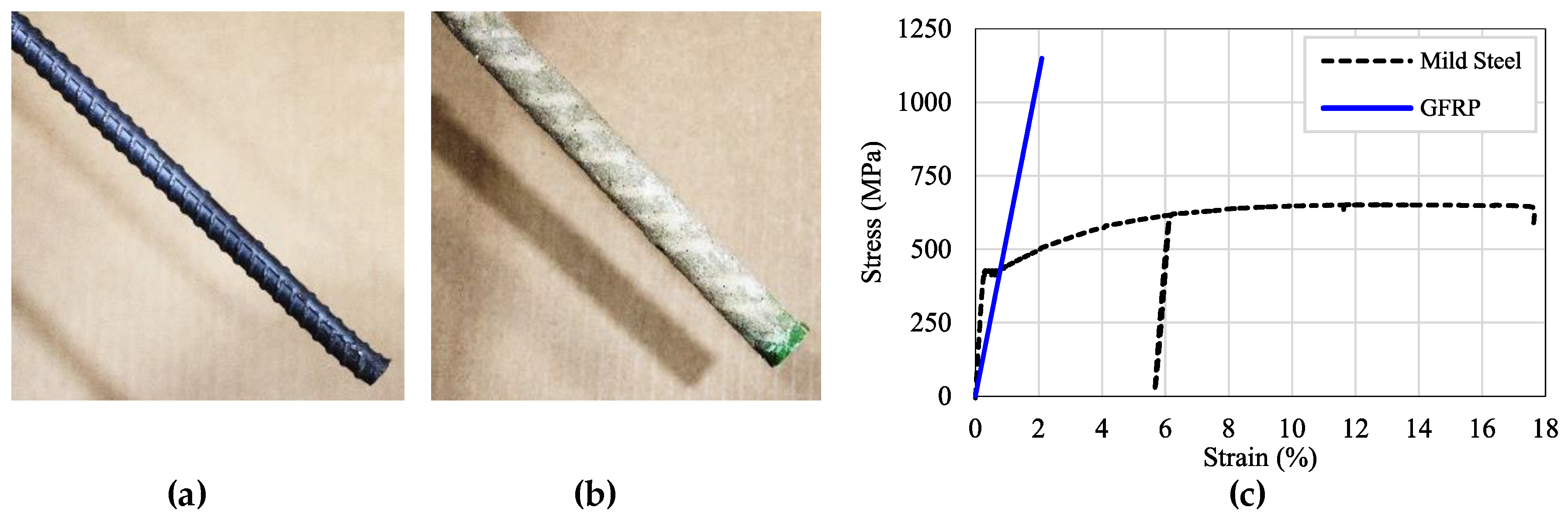
2.1. Materials
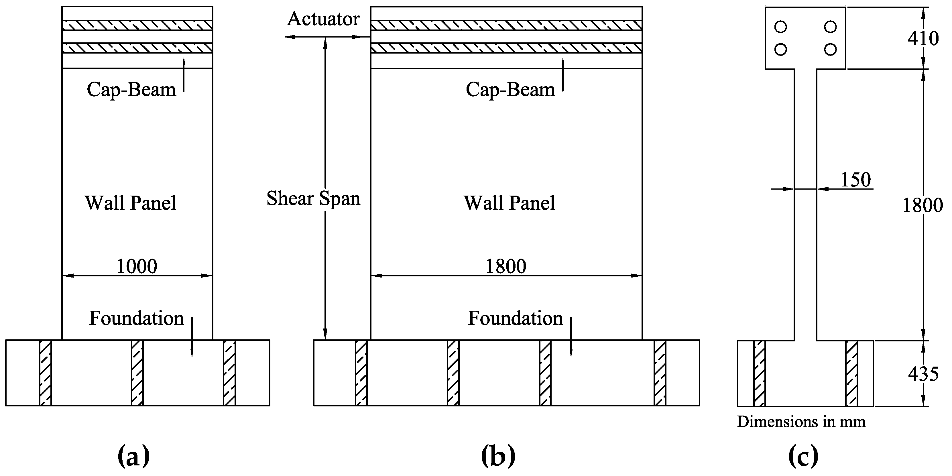
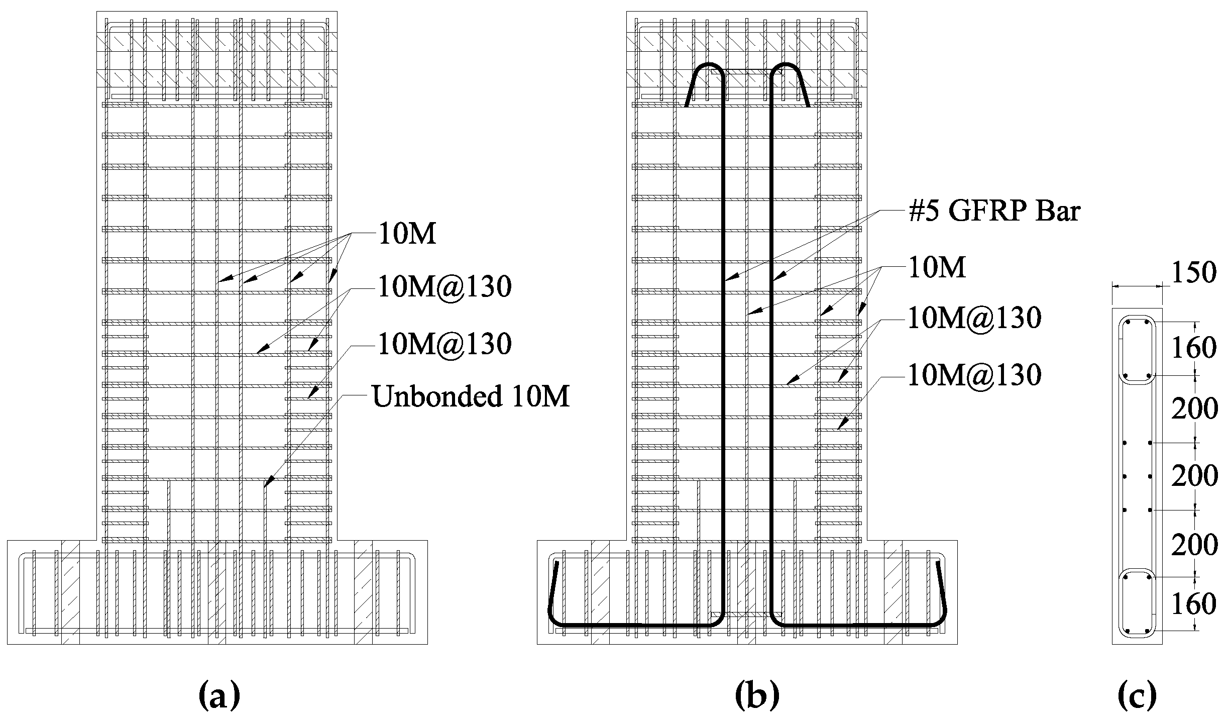
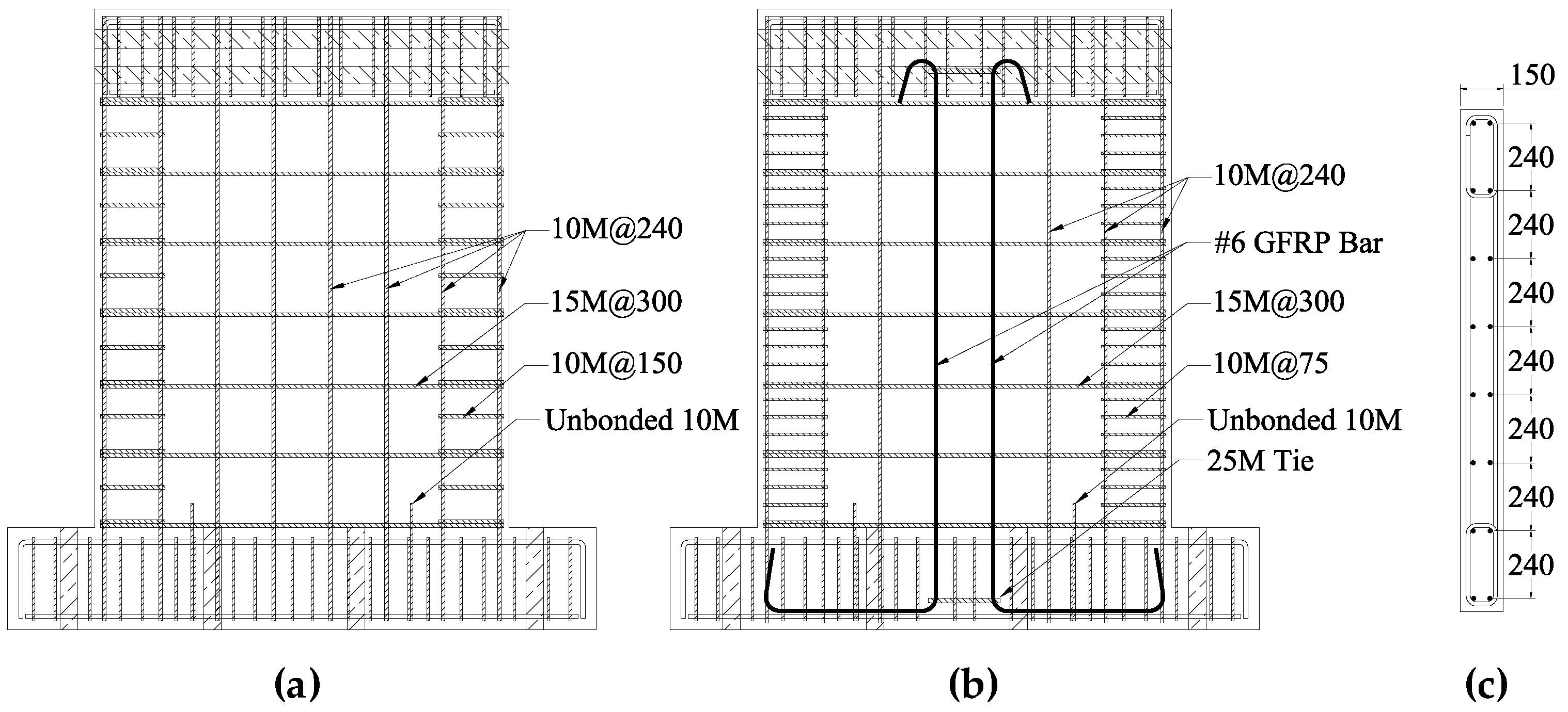
2.2. Test Specimens
3. Results
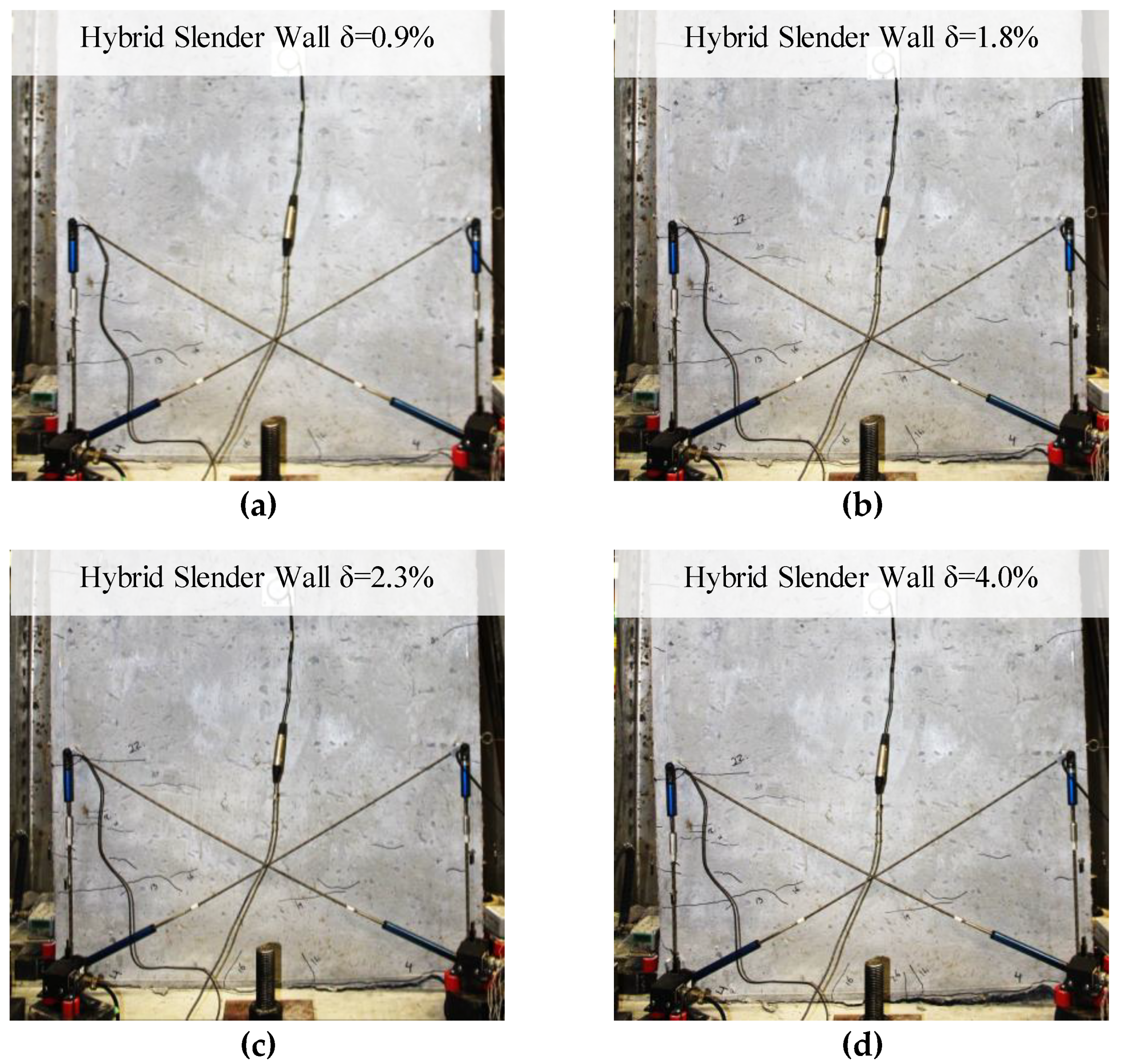
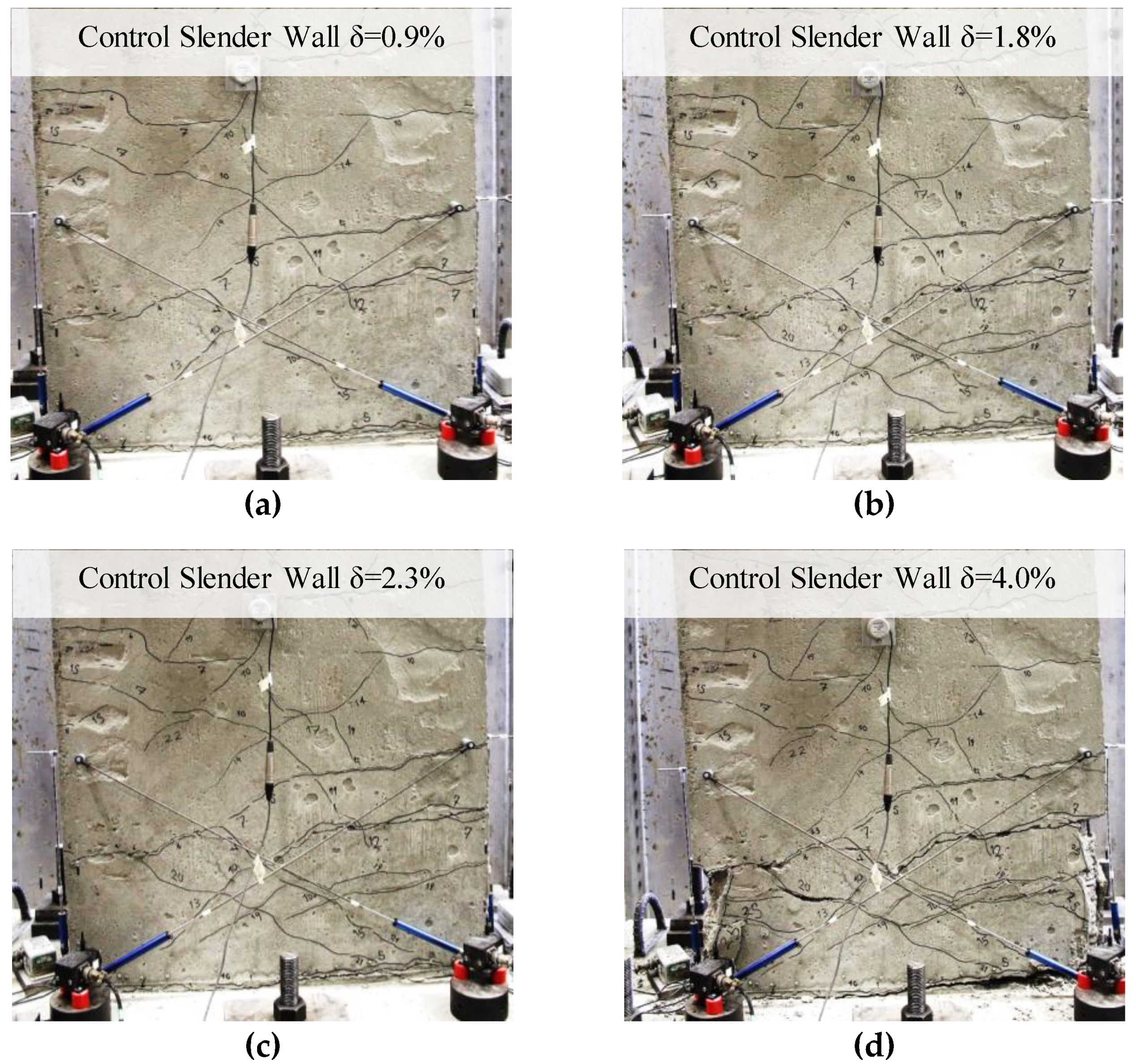
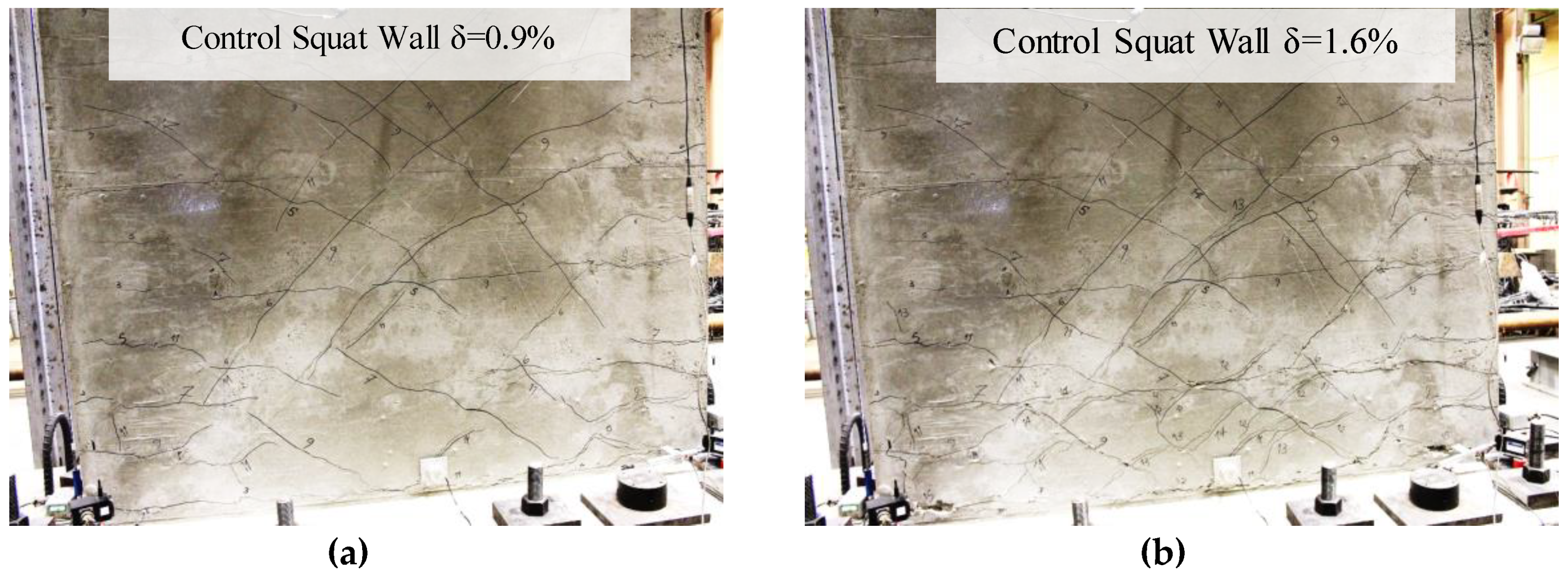
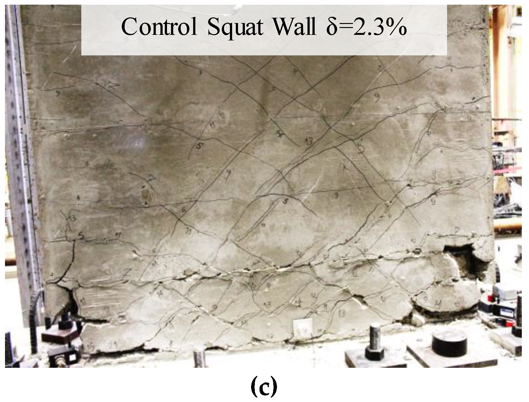
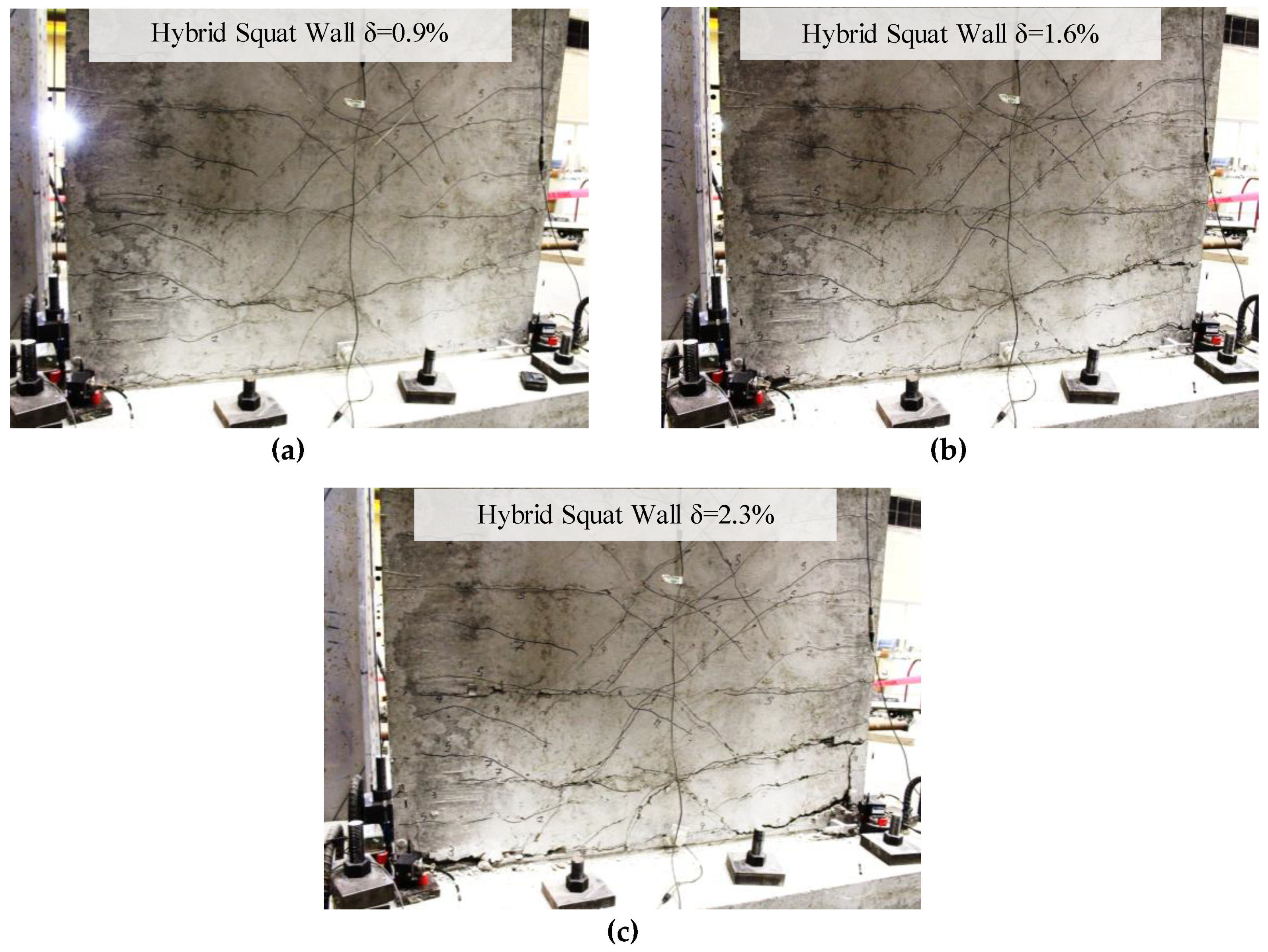
3.1. Damage Propagation
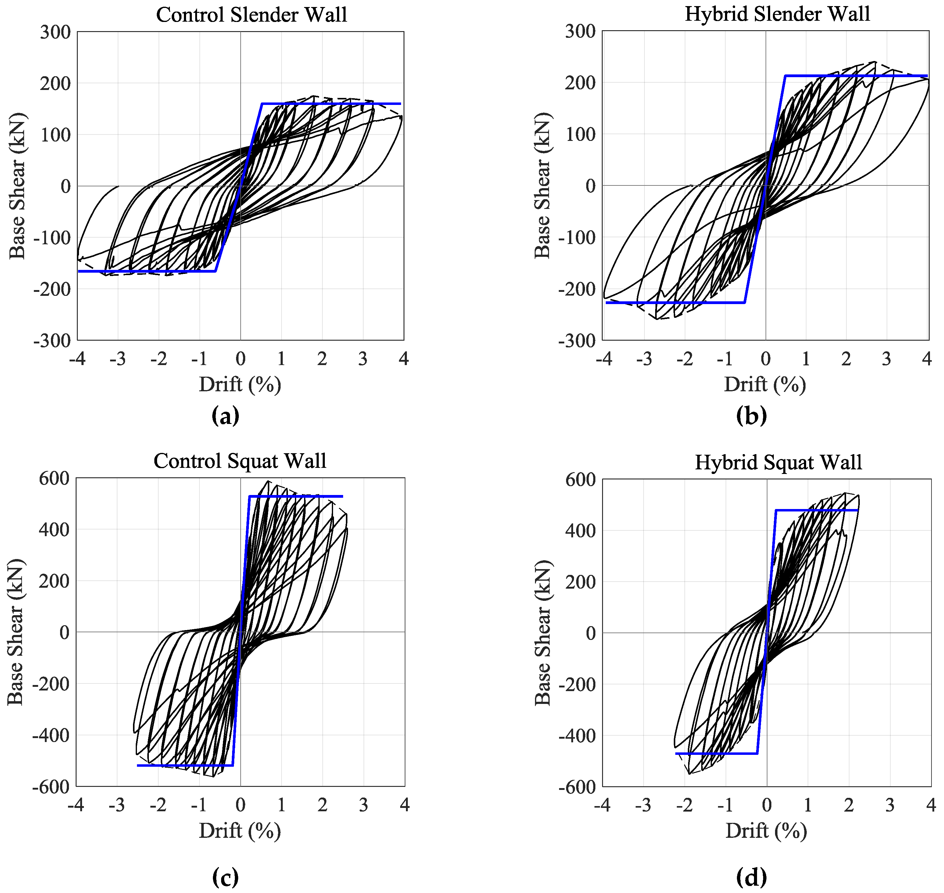
3.2. Hysteretic Response
3.3. Self-Centering
3.4. Hysteretic Stiffness
3.5. Hysteretic Energy Dissipation
4. Discussions
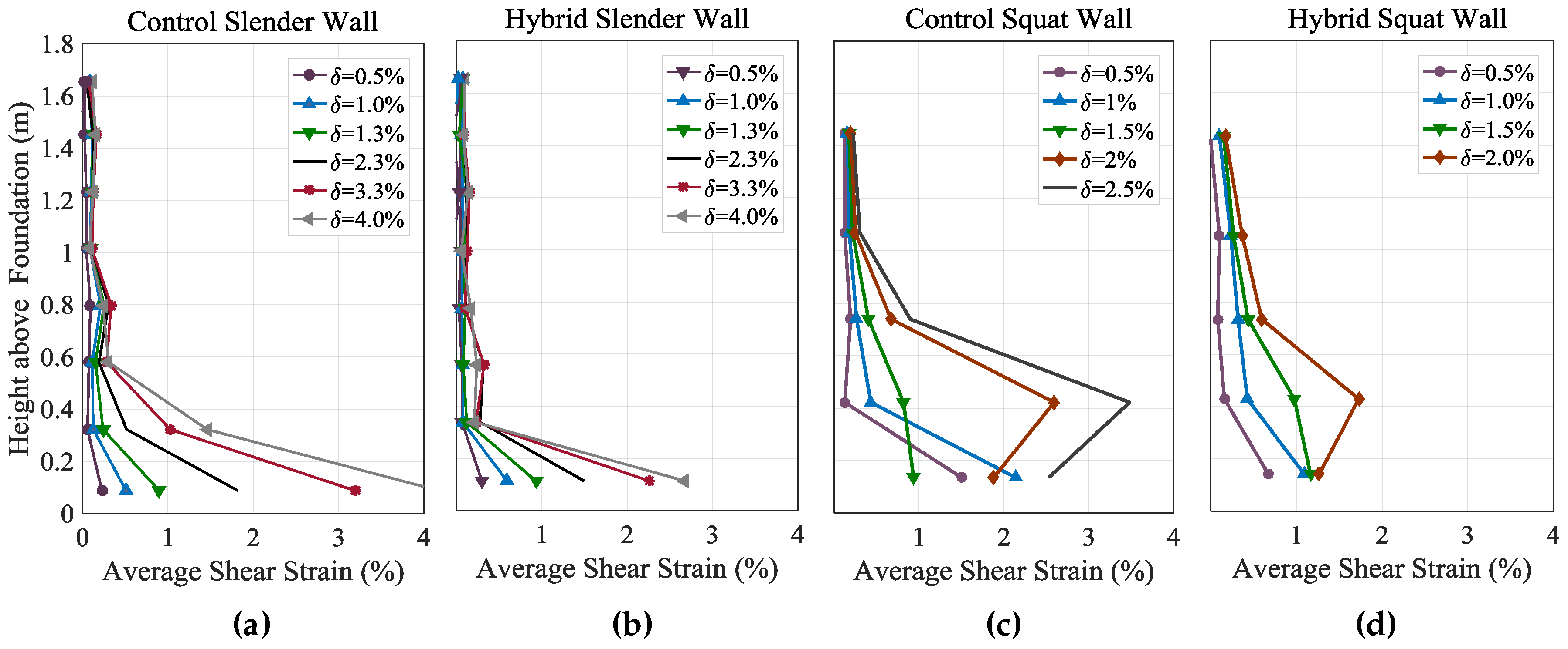
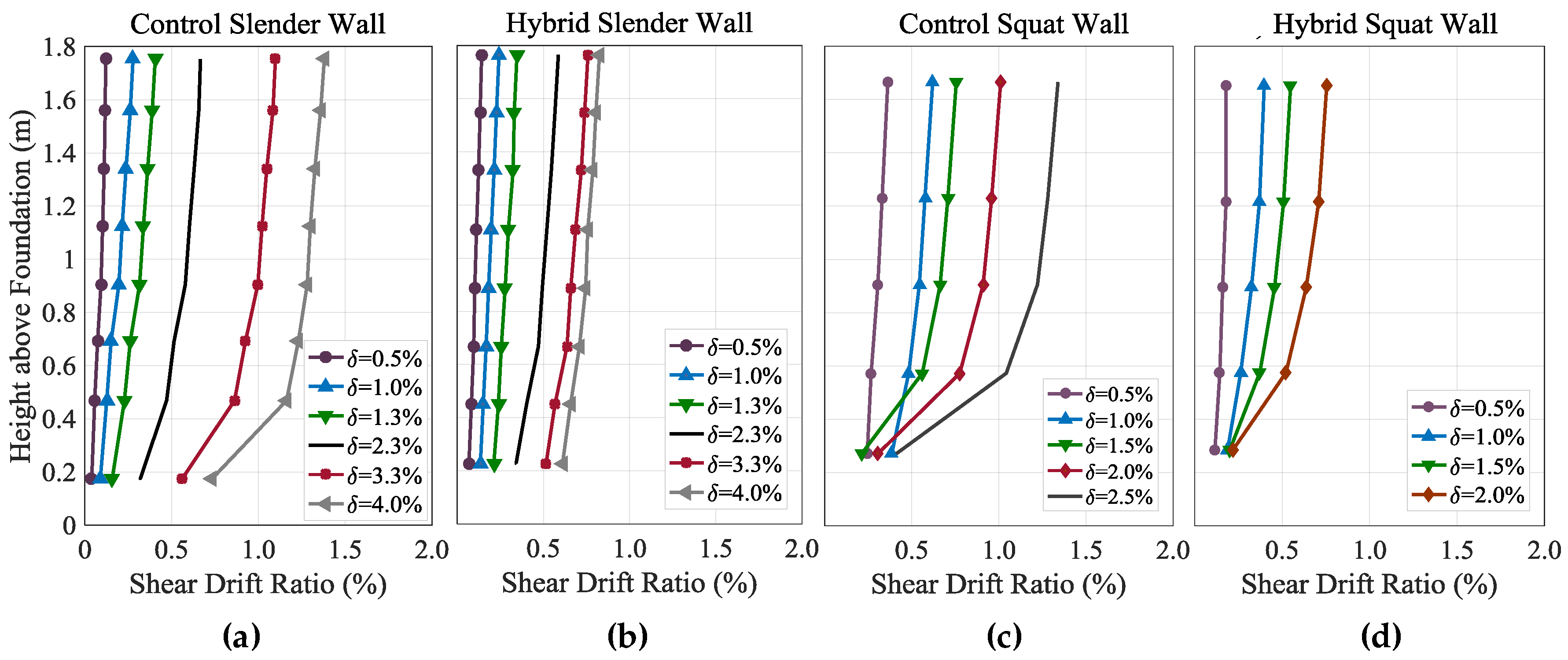
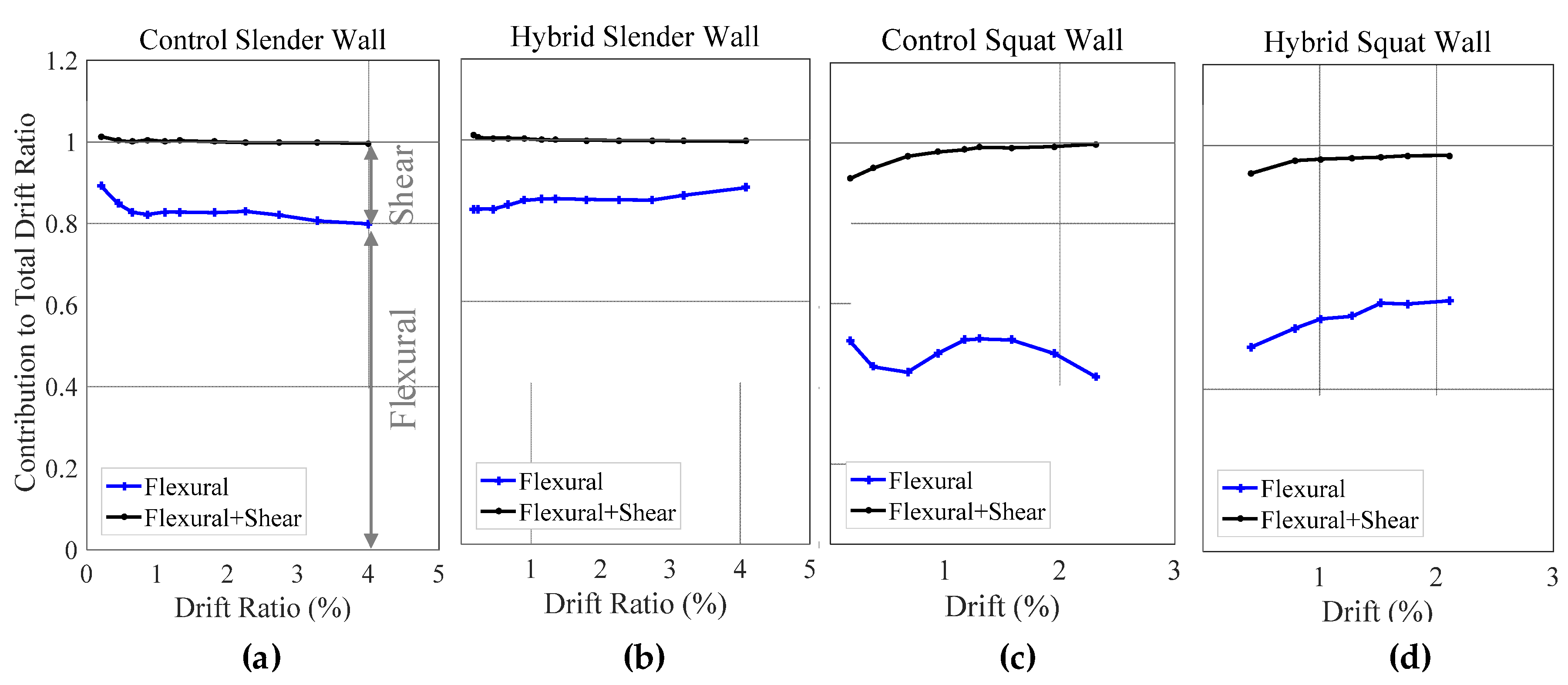
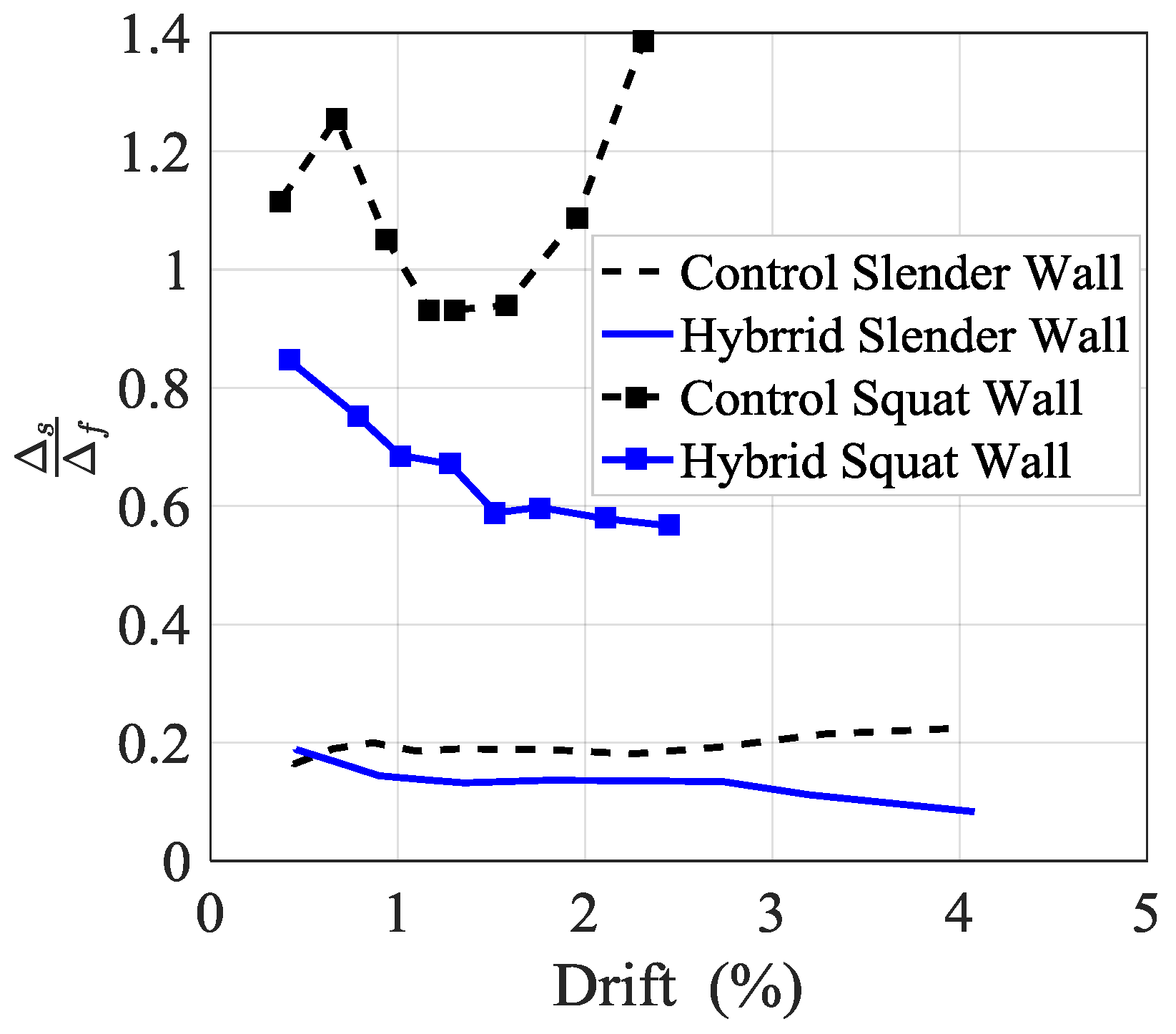
- The responses of the slender walls were more influenced by flexure than shear, as flexural deformations contributed to about 80% of lateral displacements of the slender walls, while they were responsible for 42% to 62% of the displacements affecting the squat walls. For this reason, it can be concluded that detailing RC shear walls with vertical GFRP bars is more effective in reducing the residual drift ratios of slender shear walls in comparison to squat shear walls. Regarding squat walls, other preparations should also be considered to decrease the residual shear drift ratios of the walls. Also, detailing slender and squat walls with GFRP bars decreased the shear deformations of the walls with respect to their control specimens.
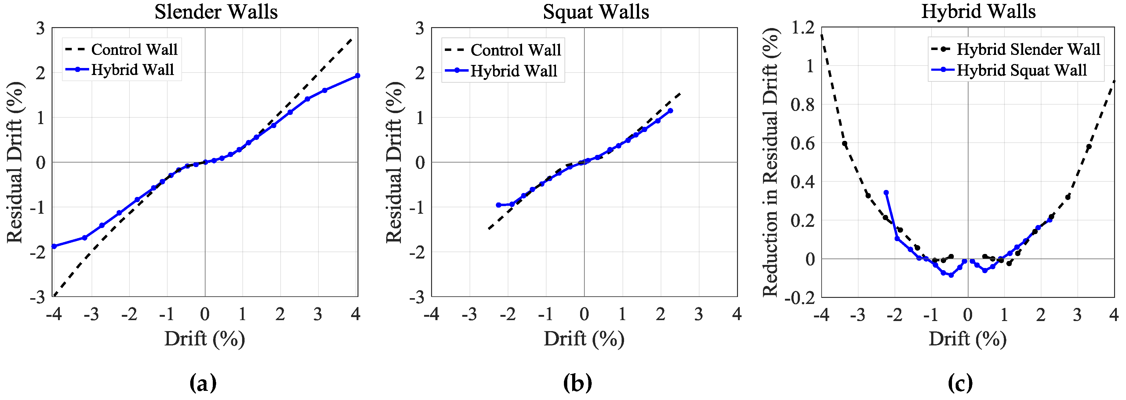
- Both hybrid slender and squat specimens had slightly greater residual drift ratios in comparison to their control shear walls at drift ratios of 1.0% and smaller. Then the walls showed lower residual drift ratios than their corresponding control walls for drift ratios greater than 1.0%. For this reason, detailing shear walls with GFRP bars could be more effective in improving the collapse prevention seismic performance of the shear walls, rather than their immediate occupancy levels.
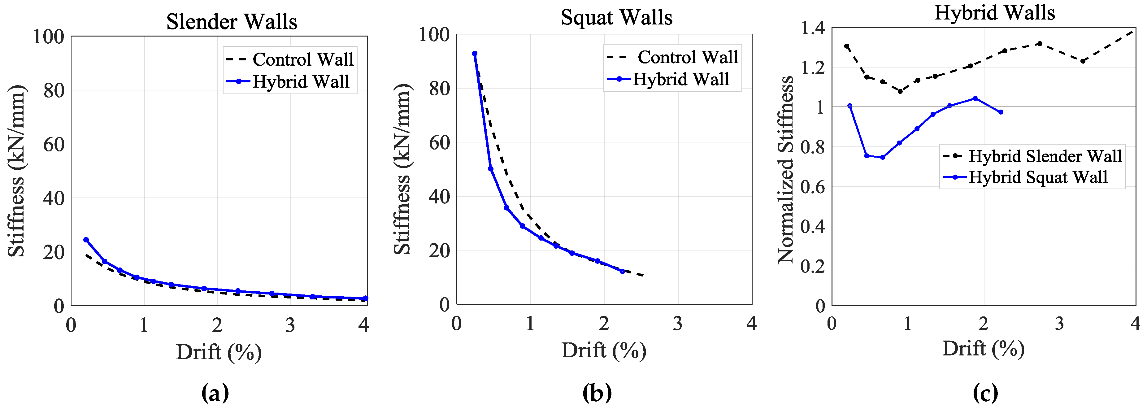
- Special considerations should be taken into account to provide GFRP-reinforced shear walls with adequate levels of stiffness. In this study, the hybrid squat wall, which had a comparable lateral load capacity to the control squat wall, showed lower stiffness in comparison to the control squat wall after cracking, which can impose some problems on the serviceability of the wall. On the other hand, the hybrid slender wall, which had a higher strength than the control slender wall, maintained a higher stiffness.
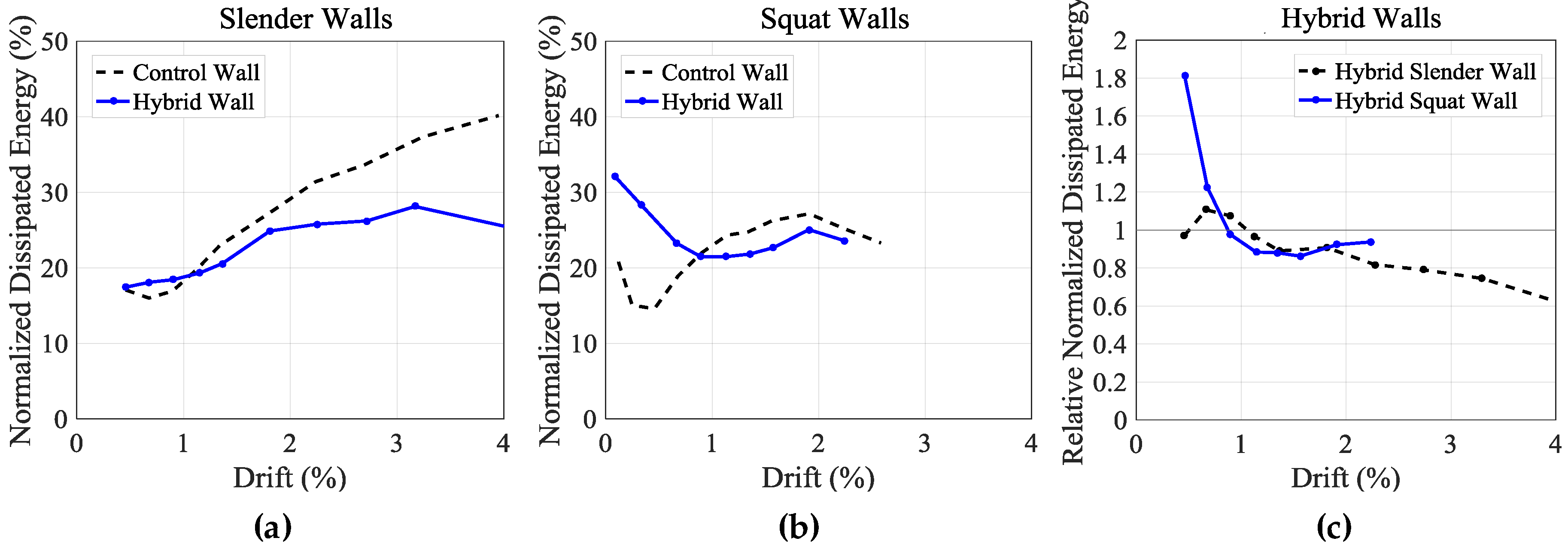
- Both hybrid shear walls dissipated significant amounts of energy. The hybrid specimens showed greater energy dissipation capacities in comparison to their control walls for drift ratios of 1.0% and smaller, when the walls had greater residual drifts than their control walls. However, as the hybrid walls started to have lower residual drifts than their control walls, the energy dissipation capacities of the walls dropped below those of their control walls.
- The hybrid shear walls displayed comparable ductility indices in comparison to their corresponding control walls. Also, the failures of the hybrid walls were triggered by the failure of their outmost steel rebars, meaning that brittle GFRP bars were well protected in the webs of the hybrid walls.
- Due to the fiber reinforcement of the hybrid specimens, the walls sustained mitigated damage in comparison to their control walls. In effect, the hybrid walls sustained less cover spalling and fewer concrete cracks.
- Future studies can focus on the development of valid analytical and finite-element models based on the available experimental data.
Author Contributions
Funding
Acknowledgments
Conflicts of Interest
References
- Wu, Y.; Liu, T.; Oehlers, D.J. Fundamental principles that govern retrofitting of reinforced concrete columns by steel and FRP jacketing. Adv. Str. Eng. 2006, 9, 507–533. [Google Scholar] [CrossRef]
- Mohamed, H.M.; Afifi, M.Z.; Benmokrane, B. Performance evaluation of concrete columns reinforced longitudinally with FRP bars and confined with FRP hoops and spirals under axial load. J. Bridge Eng. 2014, 19, 1–12. [Google Scholar] [CrossRef]
- Mohamed, N.; Farghaly, A.; Benmokrane, B.; Neale, K.W. Experimental investigation of concrete shear walls reinforced with glass fiber–reinforced bars under lateral cyclic loading. J. Compos. Constr. 2014, 18, 1–10. [Google Scholar] [CrossRef]
- Ghazizadeh, S.; Cruz-Noguez, C.A. Damage-resistant reinforced concrete low-rise walls with hybrid GFRP-steel reinforcement and steel fibers. J. Compos. Constr. 2018, 22, 04018002. [Google Scholar] [CrossRef]
- Ghazizadeh, S.; Cruz-Noguez, C.A.; Talaei, F. Analytical model for hybrid FRP-steel reinforced shear walls. Eng. Str. 2018, 156, 556–566. [Google Scholar] [CrossRef]
- Cai, Z.K.; Daiyu, W.; Zhenyu, W. Full-scale seismic testing of concrete building columns reinforced with both steel and CFRP bars. Compos. Str. 2017, 178, 195–209. [Google Scholar] [CrossRef]
- Parra-Montesinos, G.J.; Kim, K.Y. Seismic behavior of low-rise walls constructed with strain-hardening fiber reinforced cement composites. In Proceedings of the 13th World Conference on Earthquake Engineering, Vancouver, BC, Canada, 1–6 August 2004. [Google Scholar]
- American Society of Testing Materials (ASTM). Standard Test Methods and Definitions for Mechanical Testing of Steel Products, ASTM A370-14. Available online: https://www.scribd.com/document/342633217/A370-14-Standard-Test-Methods-and-Definitions-for-Mechanical-Testing-of-Steel-Products (accessed on 14 August 2018).
- American Society of Testing Materials (ASTM). Standard Test Method for Compressive Strength of Cylindrical Concrete Specimens, ASTM C39/C39M-15a. Available online: http://www.c-s-h.ir/wp-content/uploads/2015/01/C-39.pdf (accessed on 14 August 2018).
- Canadian Standards Association (CSA). Design of Concrete Structures, CSA A23.3-14. Available online: https://store.csagroup.org/ccrz__ProductDetails?viewState=DetailView&cartID=&sku=A23.3-14 (accessed on 14 August 2018).
- Canadian Standards Association (CSA). Design and Construction of Building Structures with Fibre-Reinforced Polymers, CSA S806–S12. Available online: http://www.ictturkey.com/assets/images/can.csa.s806-02.pdf (accessed on 14 August 2018).
- Oesterle, R.G.; Fiorato, A.E.; Johal, L.S.; Carptenter, J.E.; Russell, H.G.; Corley, W.G. Earthquake-Resistant Structural Walls-Test of Isolated Walls; National Science Foundation: Washington, WA, USA, 1976. [Google Scholar]
- Mohamed, N.; Farghaly, A.S.; Benmokrane, B.; Neale, K.W. Drift capacity design of shear walls reinforced with glass fiber-reinforced polymer bars. Struct. J. 2014, 111, 1397–1406. [Google Scholar] [CrossRef]
- Park, R. Ductility evaluation from laboratory and analytical testing. In Proceedings of the 9th World Conference on Earthquake Engineering, Tokyo-Kyoto, Japan, 2–9 August 1988. [Google Scholar]
- Hidalgo, P.A.; Ledezma, C.A.; Jordan, R.M. Seismic behavior of squat reinforced concrete shear walls. Earthq. Spectra 2002, 18, 287–308. [Google Scholar] [CrossRef]


| Specimen | Yield Drift (%) | Ultimate Drift (%) | Ductility | Yield Strength (kN) | Effective Stiffness (kN/mm) |
|---|---|---|---|---|---|
| Control Slender | 0.52 | 3.92 | 7.3 | 159.9 | 15.6 |
| Hybrid Slender | 0.48 | 3.94 | 8.1 | 212.5 | 22.0 |
| Control Squat | 0.22 | 2.49 | 11.3 | 527.4 | 133.2 |
| Hybrid Squat | 0.22 | 2.22 | 10.0 | 478.2 | 120.0 |
© 2018 by the authors. Licensee MDPI, Basel, Switzerland. This article is an open access article distributed under the terms and conditions of the Creative Commons Attribution (CC BY) license (http://creativecommons.org/licenses/by/4.0/).
Share and Cite
Tolou Kian, M.J.; Ghazizadeh, S.; Cruz Noguez, C.A. An Experimental Investigation of FRCC Shear Walls Reinforced with Steel and GFRP Bars. J. Compos. Sci. 2018, 2, 55. https://doi.org/10.3390/jcs2030055
Tolou Kian MJ, Ghazizadeh S, Cruz Noguez CA. An Experimental Investigation of FRCC Shear Walls Reinforced with Steel and GFRP Bars. Journal of Composites Science. 2018; 2(3):55. https://doi.org/10.3390/jcs2030055
Chicago/Turabian StyleTolou Kian, Mohammad J., Sina Ghazizadeh, and Carlos A. Cruz Noguez. 2018. "An Experimental Investigation of FRCC Shear Walls Reinforced with Steel and GFRP Bars" Journal of Composites Science 2, no. 3: 55. https://doi.org/10.3390/jcs2030055
APA StyleTolou Kian, M. J., Ghazizadeh, S., & Cruz Noguez, C. A. (2018). An Experimental Investigation of FRCC Shear Walls Reinforced with Steel and GFRP Bars. Journal of Composites Science, 2(3), 55. https://doi.org/10.3390/jcs2030055