Article

Ballistic Performance of Aramid/Epoxy Composite Laminates Under FSP Impact: Experimental and Numerical Investigation


by
Carlos A. Espinosa-Domínguez
1,*,
Helvio R. Mollinedo-Ponce de León
2,
Orlando Susarrey-Huerta
3,
Marcos Rodríguez Millán
4,
Noé López-Perrusquia
1 and
Marco A. Doñu-Ruiz
1
1
Grupo Ciencia e Ingeniería de Materiales, Universidad Politécnica del Valle de México (UPVM), Av. Mexiquense S/N, Esquina con Av. Universidad Politécnica, Col. Villa Esmeralda, Tultitlán de Mariano Escobedo 54910, Estado de México, Mexico
2
UPIITA, Instituto Politécnico Nacional, Av. Instituto Politécnico Nacional No. 2580, Col. La Laguna Ticomán, Ciudad de México 07340, Mexico
3
SEPI, ESIME Unidad Zacatenco, Instituto Politécnico Nacional, Av. Luis Enrique Erro S/N, Unidad Profesional Adolfo López Mateos, Zacatenco, Ciudad de México 07738, Mexico
4
Department of Mechanical Engineering, Universidad Carlos III de Madrid, Avenida de la Universidad, 30 (Edificio Sabatini), 28911 Leganés, Madrid, Spain
*
Author to whom correspondence should be addressed.
J. Compos. Sci. 2026, 10(8), 413; https://doi.org/10.3390/jcs10080413
Submission received: 26 June 2026 / Revised: 28 July 2026 / Accepted: 31 July 2026 / Published: 4 August 2026

Abstract

The ballistic performance of a non-commercial aramid/epoxy composite laminate subjected to Fragment Simulating Projectile (FSP) impact was investigated through combined experimental testing and numerical simulation. Ballistic tests were performed in accordance with STANAG 2920 to determine the ballistic limit velocity (V50). Complete and partial penetration responses were identified, with the ballistic transition region occurring between 412 and 452 m/s. The experimental ballistic limit was V50 = 440.57 m/s. A three-dimensional finite element model was developed in ANSYS® AUTODYN 2026 R1 using a Lagrangian formulation and an orthotropic constitutive model incorporating elastic behavior, stress/strain-based failure criteria, post-failure response, and geometric strain erosion. The numerical simulations predicted a ballistic limit of V50 = 440.65 m/s, corresponding to a relative difference of less than 0.03% with respect to the experimental result. The numerical model successfully reproduced the ballistic transition, damage evolution, projectile velocity history, and energy transfer during impact, providing good agreement with the experimentally observed penetration responses. These results demonstrate that the proposed methodology provides a reliable and validated framework for predicting the ballistic response of aramid/epoxy composite laminates under standardized FSP impact conditions and supports the design and evaluation of lightweight composite armor systems.

1. Introduction

Composite materials have become increasingly important in aerospace, transportation, marine, and defense applications due to their high specific mechanical properties, lightweight characteristics, and energy absorption capability. Among these materials, fiber-reinforced polymer (FRP) composites have received considerable attention for ballistic protection systems, where reduced weight, structural efficiency, and damage tolerance are essential requirements. The combination of high-performance fibers and polymer matrices enables the development of lightweight protective structures with enhanced mechanical performance. Recent advances in aramid-based composites and hybrid armor architectures have expanded their application potential in next-generation ballistic protection systems [1,2,3,4,5].
Ballistic impact represents a complex high-rate loading condition in which multiple damage mechanisms develop simultaneously, including fiber fracture, matrix cracking, delamination, and localized deformation. The interaction between these mechanisms governs the energy absorption capability and ballistic resistance of composite laminates. Experimental investigations on Kevlar and other high-performance fibers have provided fundamental knowledge regarding penetration behavior, failure mechanisms, and the influence of impact parameters such as projectile characteristics, velocity, and laminate configuration [6,7,8,9,10,11].
Aramid fibers are widely used in ballistic protection applications due to their high tensile strength, low density, and excellent energy absorption capability. When combined with polymeric matrices, particularly epoxy resins, these fibers produce lightweight laminates with high stiffness and effective load transfer between constituents. However, the ballistic response of aramid/epoxy composites depends strongly on fiber architecture, interfacial behavior, matrix properties, and manufacturing conditions, making accurate prediction of their mechanical response a challenging task [2,4,5,9,12,13,14].
The development of numerical methodologies has significantly contributed to understanding and predicting the behavior of composite materials subjected to dynamic impact loading. Early hydrocode formulations established the basis for simulating high-rate phenomena, while subsequent constitutive models incorporated anisotropic behavior, damage evolution, and failure mechanisms associated with composite materials. These advances have enabled more accurate predictions of deformation, delamination, and ballistic response under severe loading conditions [15,16,17,18,19,20,21].
Finite element and hydrocode simulations, including ABAQUS/Explicit, LS-DYNA, and AUTODYN approaches, have been extensively applied to evaluate the ballistic response of composite laminates and protective structures. Numerical investigations have analyzed the influence of projectile characteristics, laminate thickness, material configuration, and failure modeling strategies on energy absorption and penetration behavior. Recent studies have improved numerical predictions through refined constitutive models, failure criteria, and computational strategies capable of reproducing the complex damage mechanisms occurring in composite laminates under ballistic impact [8,22,23,24,25].
Beyond flat composite laminates, numerical and experimental studies have been extended to complex protective structures, particularly ballistic helmets, where geometry, impact location, and structural configuration strongly influence protective performance. Finite element models have been employed to evaluate helmet resistance, predict impact response, and optimize protective designs under different projectile conditions [26,27,28,29,30].
Recent research has also focused on hybrid composite architectures as a strategy to enhance ballistic resistance through the combination of complementary materials. The incorporation of ceramic layers, metallic reinforcements, shape memory alloys, and modified polymer matrices has demonstrated the potential to improve energy absorption, damage tolerance, and overall ballistic performance compared with conventional composite laminates [31,32,33,34].
Despite significant progress in experimental characterization and numerical modeling, accurately predicting the ballistic limit velocity (V50) of composite materials remains challenging due to the complex interaction between material properties, failure mechanisms, and impact conditions. Standardized evaluation methods, such as STANAG 2920, provide a reference framework for ballistic testing and comparison of protective materials; however, the correlation between experimental measurements and numerical predictions continues to require further validation for advanced composite systems [35,36].
Therefore, this study investigates the ballistic performance of a non-commercial, in-house manufactured aramid/epoxy composite laminate subjected to Fragment Simulating Projectile (FSP) impact through a combined experimental and numerical approach. The ballistic limit velocity (V50) is experimentally determined and compared with numerical predictions obtained using ANSYS® AUTODYN. The main contribution of this work is the validation of a numerical methodology capable of reproducing the ballistic response of a custom-developed aramid/epoxy laminate, providing a reliable framework for the design and evaluation of lightweight composite protection systems.

2. Materials and Methods

2.1. Composite Laminate and Projectile Properties

Aramid fiber/epoxy composite laminates with an areal density of 200 g/m2 were manufactured using a vacuum bagging process. The laminates consisted of 28 layers arranged in a 0°/90° stacking sequence. Detailed information regarding the manufacturing procedure, physical characterization, and processing conditions has been previously reported by Espinosa-Domínguez et al. [5].
The laminate panels were fabricated with nominal dimensions of 400 × 400 × 5 mm according to the requirements established in NOM-142-SCFI-2000 and STANAG 2920 [35,36]. These standards define the testing procedures and performance requirements for ballistic-resistant materials and personal protection systems.
The material, geometry, and dimensions of the Fragment Simulating Projectiles (FSPs) were defined according to STANAG 2920 [35]. The standard specifies 4340 steel projectiles of caliber 0.22 (Type 1, armor-piercing) with a nominal mass of 1.1 g, which are commonly employed for evaluating the ballistic resistance of protective materials.

2.2. Finite Element Model and Numerical Setup

The ballistic impact simulations were performed using the Explicit Dynamics module of ANSYS® AUTODYN, which is suitable for highly nonlinear dynamic problems involving large deformation, high strain rates, and complex failure mechanisms. The impact event between the FSP and the aramid/epoxy composite laminate was modeled using the finite element method (FEM).
The composite laminate was represented using a macromechanical orthotropic material formulation. Orthotropic materials exhibit three mutually perpendicular planes of elastic symmetry, resulting in different mechanical responses along the principal material directions. Therefore, the laminate was modeled as an equivalent homogeneous orthotropic material using the constitutive formulation proposed for anisotropic materials under dynamic loading conditions [16,17,20].
The material response was defined through the coupling of an equation of state (EOS) and a constitutive strength model. The EOS describes the relationship between pressure and internal energy, while the strength formulation defines the deviatoric stress response associated with material deformation. In the present work, the elastic strength model was adopted to describe the initial mechanical response of the aramid/epoxy laminate before failure initiation [16,20].
For an orthotropic material, the relationship between stress σ i j and strain ε i j is expressed through the stiffness matrix C i j , as shown in Equation (1):
σ } = C { ε
Following Anderson et al. [16], the stress response was separated into volumetric and deviatoric components, allowing the thermodynamic response defined by the equation of state to be treated independently from the material strength response. The constitutive formulation can therefore be expressed as
σ 11 σ 22 σ 33 σ 23 σ 31 σ 12 = C 11 C 12 C 13 0 0 0 C 21 C 22 C 23 0 0 0 C 31 C 32 C 33 0 0 0 0 0 0 C 44 0 0 0 0 0 0 C 55 0 0 0 0 0 0 C 66 ε 11 d + 1 3 ε v ε 22 d + 1 3 ε v ε 33 d + 1 3 ε v ε 23 d ε 31 d ε 12 d

Failure Criteria

The onset of failure in the aramid/epoxy laminate was defined using the Material Stress/Strain failure criterion implemented in AUTODYN. This criterion evaluates the stress and strain components along the principal orthotropic directions and predicts failure when the corresponding allowable limits are exceeded. Such approaches have been widely applied for representing the directional failure behavior of composite materials subjected to dynamic loading conditions [16,17,20,21].
Once the failure criterion is satisfied, the material response is modified according to the selected Orthotropic post-failure formulation, which accounts for the reduction in load-carrying capability along the damaged material directions. This approach enables the numerical representation of directional damage mechanisms commonly observed in composite laminates, including fiber failure, matrix cracking, and interlaminar degradation [16,20,21].
For composite laminates, failure in the through-thickness direction σ 33 produces a loss of stress-carrying capability in that direction. Consequently, the damaged constitutive response is modified as follows:
Δ σ 11 Δ σ 22 Δ σ 33 Δ σ 23 Δ σ 31 Δ σ 12 = C 11 C 12 0 0 0 0 C 21 C 22 0 0 0 0 0 0 0 0 0 0 0 0 0 α C 44 0 0 0 0 0 0 α C 55 0 0 0 0 0 0 α C 66 Δ ε 11 Δ ε 22 Δ ε 33 Δ ε 23 Δ ε 31 Δ ε 12
The reduction in shear stiffness associated with the damaged state is represented by the parameter α (0 ≤ α ≤ 1). This parameter controls the reduction in the corresponding shear moduli after failure initiation, allowing the orthotropic degradation behavior of the composite laminate to be reproduced [16,20].
In-plane failure occurs when the stress and/or strain limits are exceeded along the principal material directions (1, 2, or 3). Once failure is detected in a specific direction, the corresponding stress component is reduced according to the post-failure formulation. Assuming failure in the 2-direction, the damaged constitutive matrix can be expressed as
Δ σ 11 Δ σ 22 Δ σ 33 Δ σ 23 Δ σ 31 Δ σ 12 = C 11 0 C 13 0 0 0 0 0 0 0 0 0 C 31 0 C 33 0 0 0 0 0 0 α C 44 0 0 0 0 0 0 α C 55 0 0 0 0 0 0 α C 66 Δ ε 11 Δ ε 22 Δ ε 33 Δ ε 23 Δ ε 31 Δ ε 12
When failure occurs simultaneously in all three principal directions, the material loses its deviatoric load-carrying capability and is only able to support hydrostatic pressure, representing the fully damaged condition of the composite material [16,20].
To control excessive element distortion during projectile penetration, erosion was defined using the Instantaneous Geometric Strain criterion available in AUTODYN. Elements exceeding the prescribed geometric strain limit were removed from the computational domain, preventing numerical instability caused by severe deformation while maintaining the physical representation of material failure during ballistic impact.

2.3. Numerical Modeling of Ballistic Impact in Composite Laminates

The aramid/epoxy composite laminate was modeled using the actual dimensions of the manufactured plate (400 × 400 × 5 mm), according to the geometric requirements established in NOM-142-SCFI-2000 [36].
A three-dimensional Lagrangian formulation was adopted to discretize the laminate geometry, since this approach is suitable for representing large deformations, material distortion, and failure phenomena occurring during high-velocity impact events. In AUTODYN, the computational domain is defined using structured mesh zoning directions denoted as I, J, and K, which correspond to the number of cells along the longitudinal, transverse, and thickness directions of the model, respectively.
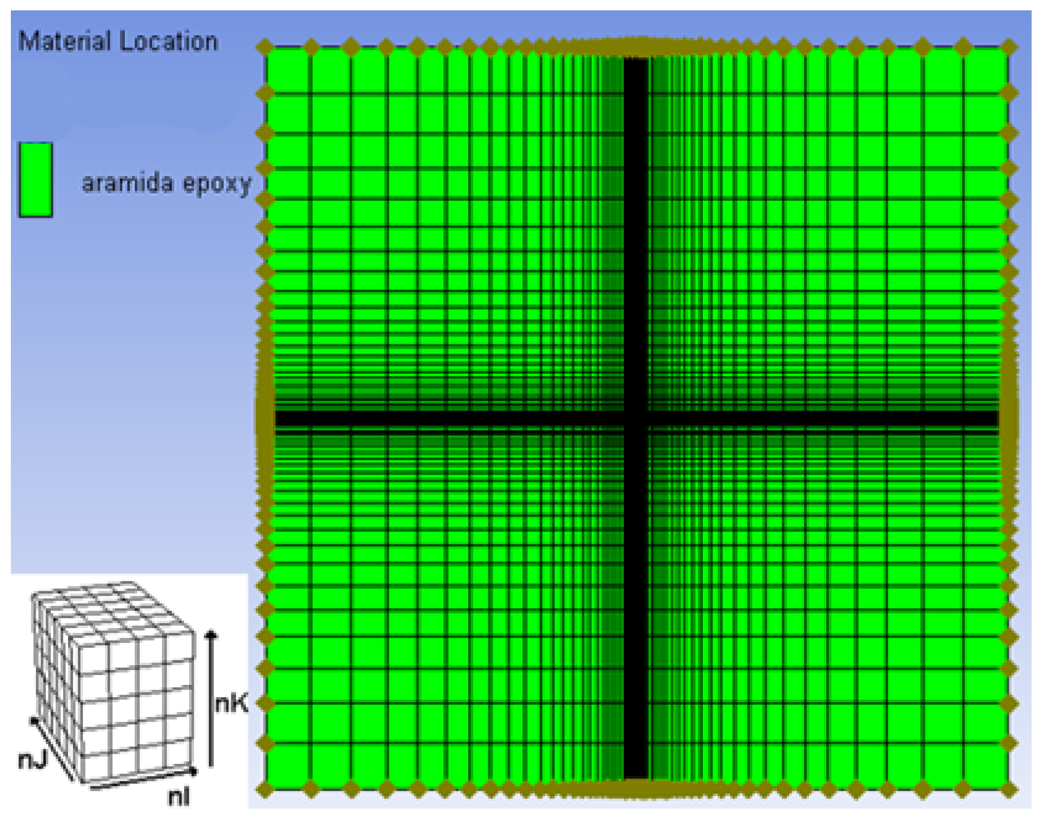
The finite element mesh was defined using I = 59, J = 59, and K = 27 divisions, resulting in a total of 100,800 nodes and 92,987 elements. A structured mesh with a uniform in-plane element size of approximately 0.5 mm was employed in the I and J directions to provide adequate spatial resolution in the projectile impact region, as illustrated in Figure 1. The selected discretization was established considering previous numerical investigations of ballistic impact on aramid-based composite laminates and protective structures, where explicit dynamic formulations with refined mesh configurations have been successfully applied to reproduce penetration behavior and damage development [9,22,26].
A full three-dimensional model was employed instead of a quarter-symmetry configuration. Although the geometry exhibits apparent symmetry, the orthotropic nature of the laminate and the possibility of asymmetric damage development, including localized delamination, fiber breakage, and non-uniform deformation, may influence the predicted impact response. Therefore, the complete laminate geometry was modeled to capture the local deformation field and failure behavior during projectile penetration.
An orthotropic material model was assigned to represent the mechanical response of the aramid/epoxy composite laminate. The material parameters required for numerical simulation, including elastic constants, strength limits, and failure parameters, were obtained from previously reported experimental and numerical studies on aramid/epoxy composite systems [9,13,26]. The implemented constitutive formulation was defined using the Orthotropic Equation of State (EOS), Elastic Strength model, Material Stress/Strain failure criterion, Orthotropic post-failure response, and Instantaneous Geometric Strain erosion criterion available in AUTODYN.
The selected constitutive formulation has been widely applied for the numerical evaluation of aramid-based composites subjected to dynamic impact loading. These approaches allow the representation of directional mechanical behavior, anisotropic response, and reduction in load-carrying capability after failure initiation [16,17,20,21]. The mechanical and failure parameters implemented in the numerical model are summarized in Table 1.

2.3.1. Modeling of the FSP

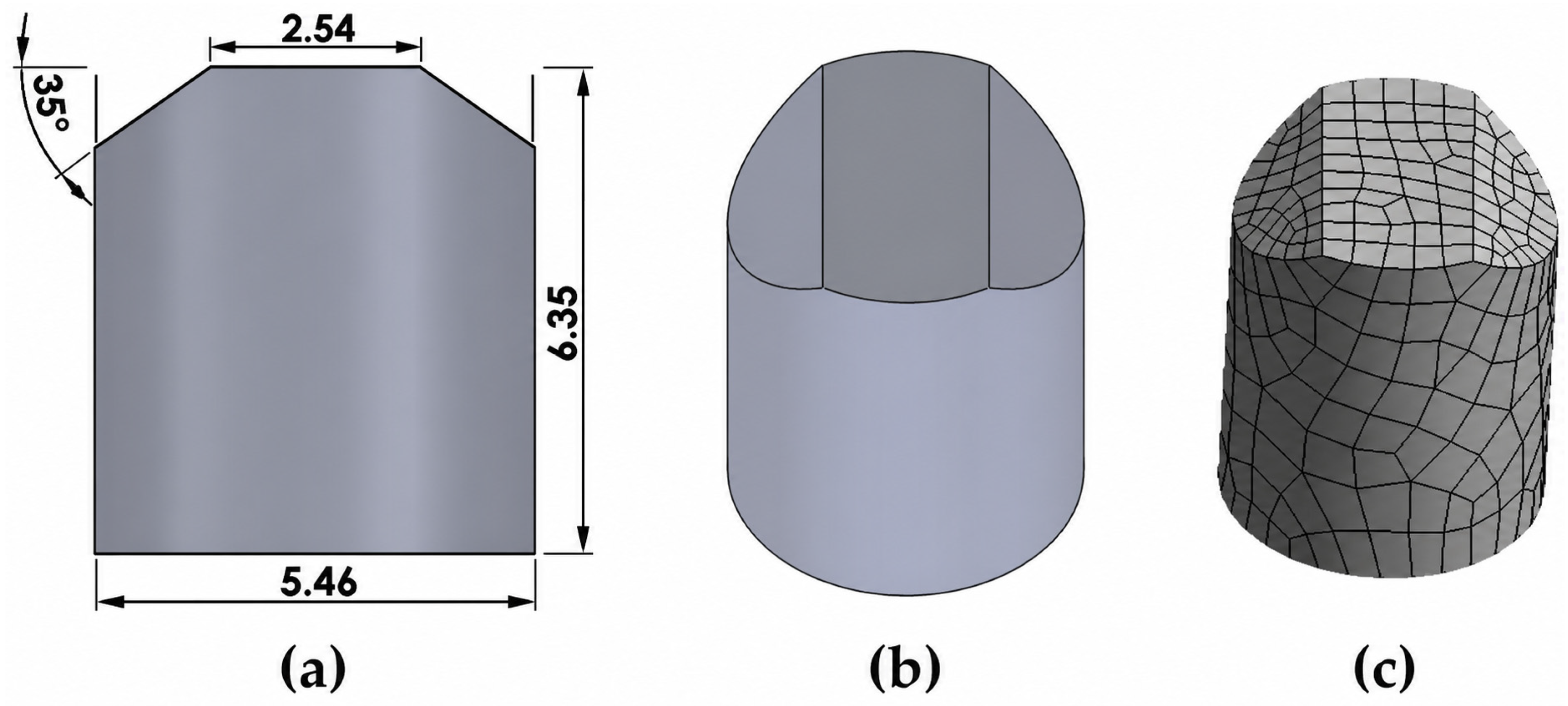
The projectile geometry and characteristics were defined according to STANAG 2920 [35], which specifies the use of a 0.22 caliber Fragment Simulating Projectile (FSP) for ballistic testing. The projectile presents a nominal diameter of 5.46 mm and a mass of 1.1 g.
A Lagrangian formulation was adopted for the projectile, which was modeled as a rigid body during the impact event. Considering the high hardness of the AISI 4340 steel projectile and the limited deformation observed after impact, the rigid-body assumption was employed to reduce computational cost while maintaining an accurate representation of the projectile–target interaction.
The projectile material was defined as AISI 4340 steel according to STANAG 2920 [35]. The reference density value of 7.83 g/cm3 was obtained from the AUTODYN material database.
The FSP geometry was discretized using an explicit linear mesh formulation with a nominal element size of 0.9 mm. According to the mesh statistics generated in AUTODYN, the projectile discretization consisted of 290 nodes and 1088 elements. The selected mesh density provided an adequate representation of the projectile geometry and contact interface while maintaining computational efficiency during the high-velocity impact simulations.
The geometric characteristics of the FSP are illustrated in Figure 2.

2.3.2. Boundary Conditions

Appropriate initial and boundary conditions were defined to reproduce the ballistic impact conditions observed during the experimental tests.
The composite laminate was modeled using fully clamped boundary conditions by applying a General 3D Velocity boundary condition to all nodes located along the plate edges, as illustrated in Figure 1. The translational velocity components were prescribed as V x = 0 , V y = 0 , and V z = 0 , while the rotational velocity components were prescribed as R x = 0 , R y = 0 , and R z = 0 throughout the simulation. Consequently, the constrained edge nodes remained fully fixed, preventing translational motion, rotational motion, and boundary slippage during impact, whereas the remaining nodes of the laminate were allowed to deform freely according to the adopted orthotropic constitutive formulation and failure criteria.
The adopted boundary conditions were selected to reproduce the rigid clamping configuration used during the experimental ballistic tests. Since the propagation of stress waves and the development of back-face deformation are affected by the support conditions, maintaining consistency between the numerical and experimental configurations was necessary to accurately predict the laminate response during projectile impact.
The FSP was positioned at the center of the laminate and placed close to the target surface to ensure immediate contact. An initial velocity was assigned in the direction normal to the laminate surface, corresponding to the impact velocities evaluated experimentally.
The interaction between the projectile and the composite laminate was defined using a Lagrangian–Lagrangian contact formulation with an external gap algorithm. The contact distance was automatically calculated by AUTODYN, resulting in an initial gap value of approximately 0.019 mm.

2.3.3. Experimental Tests FSP

The experimental program consisted of ballistic impact tests performed on flat aramid fiber/epoxy composite laminate plates with nominal dimensions of 400 × 400 × 5   m m . The tests were conducted in accordance with NOM-142-SCFI-2000 [36] and STANAG 2920 [35], following procedures commonly employed in ballistic evaluation and certification tests for personal protection systems.
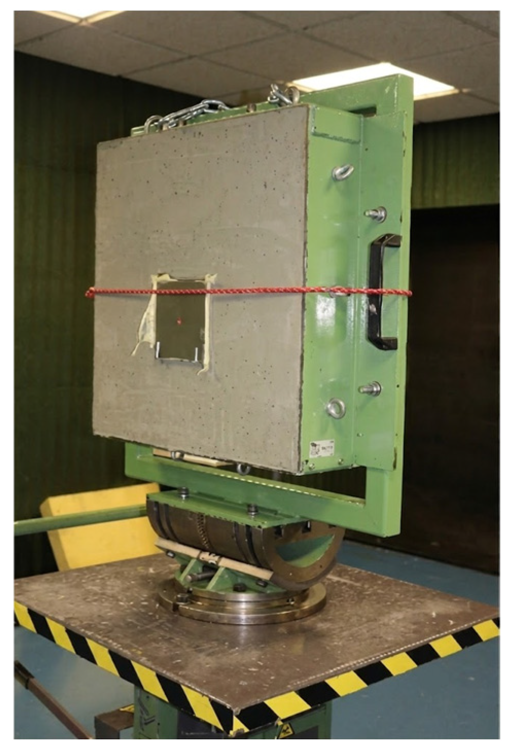
The ballistic impact tests were conducted by the specialized company FECSA under controlled testing conditions. During testing, the specimens were fully clamped along their edges to reproduce a fixed support condition during impact. Figure 3 illustrates the clamping fixture and support configuration employed during the ballistic impact tests.
The composite laminates were impacted using six FSPs with a diameter of 5.46 mm and a nominal mass of 1.1 g. The ballistic limit velocity V 50 is defined as the velocity at which the projectile has a 50% probability of completely perforating the target material. According to STANAG 2920 [35], the V 50 value is determined using an even number of impact events (minimum of six), calculated as the arithmetic mean of velocities corresponding to an equal number of partial and complete perforations. The difference between the highest and lowest velocities within the selected group must not exceed 40 m/s.
The velocity range considered for the ballistic tests was 412 < V 0 < 453   m / s . In all the experiments, the projectiles did not exhibit significant deformation, erosion, or damage after impact.

3. Results

3.1. Experimental FSP Results

Ballistic impact tests were conducted on the manufactured aramid/epoxy composite laminates using Fragment Simulating Projectiles (FSPs) in accordance with the STANAG 2920 ballistic test procedure. The experimental results are summarized in Table 2.
The experimental results revealed two distinct ballistic responses: complete penetration (CP) and partial penetration (PP). Partial penetration was characterized by projectile arrest within the laminate, whereas complete penetration occurred when the projectile fully penetrated the target.
A transition region between partial and complete penetration was observed within an impact velocity interval of approximately 412–452 m/s. Within this range, relatively small variations in impact velocity produced different penetration responses, indicating that the laminate was tested near its ballistic limit. This transition behavior is characteristic of fiber-reinforced composite laminates subjected to high-velocity impact, where the absorbed energy approaches the critical energy required for complete penetration.
Following the procedure established in STANAG 2920, the ballistic limit velocity (V50) was calculated using the arithmetic mean of the six valid impact velocities, consisting of three complete and three partial penetration events. The resulting ballistic limit was:
V 50 = 440.57   m / s

3.2. Experimental Damage Morphology After Ballistic Impact

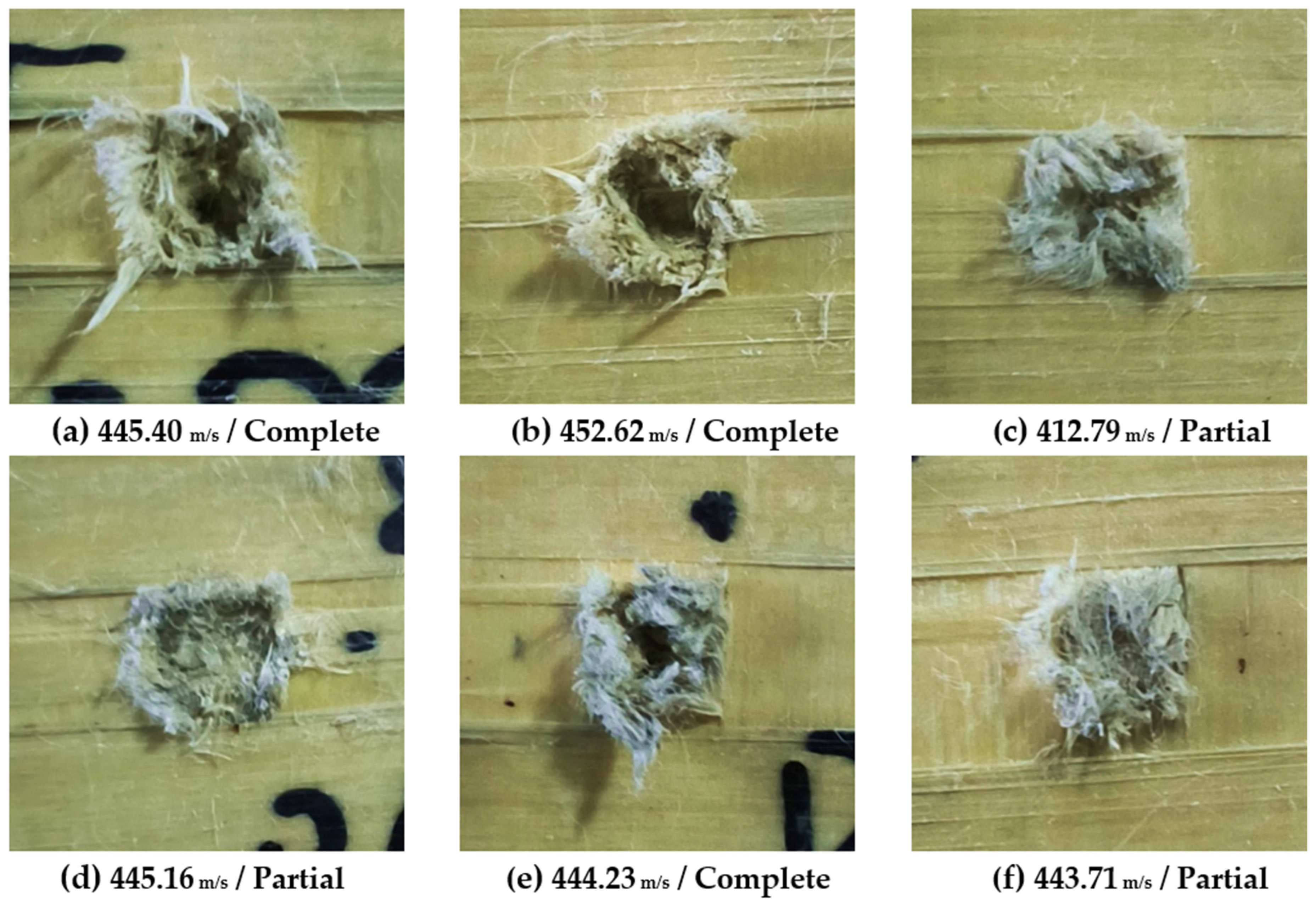
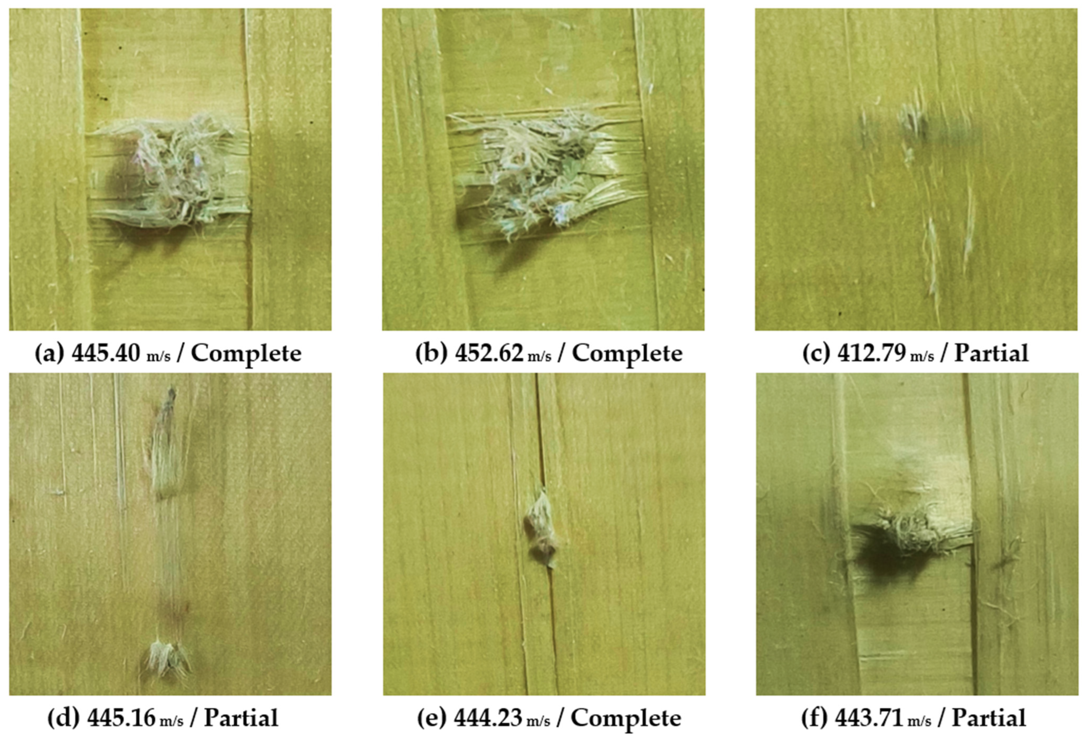
The damage morphology observed after the ballistic tests is presented in Figure 4 and Figure 5, corresponding to the front and rear faces of the aramid/epoxy composite laminates, respectively. In all the specimens, the impact damage remained localized around the projectile strike point, although the extent of surface damage depended on the impact velocity and the resulting penetration condition.
Figure 4 shows the front-face damage generated by the FSP. Complete penetration (CP) specimens exhibited larger damaged areas accompanied by pronounced fiber rupture and extensive fiber pull-out surrounding the impact zone. In contrast, partial penetration (PP) specimens displayed more confined damage with a smaller affected region, indicating that a greater proportion of the projectile kinetic energy was absorbed within the laminate without complete perforation. The most severe front-face damage was observed for impact velocities of 445.40 m/s and 452.62 m/s, where the laminate surface exhibited significant fiber extraction and material disruption.
Figure 5 presents the corresponding rear-face damage. Distinct differences between complete and partial penetration were observed. Complete penetration resulted in perforation of the laminate together with considerable fiber pull-out from the rear surface, whereas partial penetration produced localized rear-face deformation with limited fiber extraction and no complete perforation. Among the partial penetration specimens, the laminate impacted at 412.79 m/s exhibited the smallest damaged region, suggesting that the projectile kinetic energy was effectively dissipated before complete penetration occurred.
Overall, the observed failure patterns indicate that the ballistic response of the aramid/epoxy laminate was governed primarily by localized fiber rupture, fiber pull-out, and progressive deformation within the impact region. As the impact velocity approached and exceeded the ballistic limit, the extent of fiber extraction and surface damage increased, reflecting the higher amount of residual kinetic energy available to promote complete projectile penetration.

3.3. Numerical Results

Numerical simulations were performed using AUTODYN considering the same impact velocities employed in the experimental ballistic tests for the determination of the ballistic limit velocity (V50). Six representative impact conditions within the ballistic transition region were analyzed, including three complete penetration (CP) and three partial penetration (PP) events, corresponding to the experimental impact conditions summarized in Table 2.
The transient evolution of the ballistic impact process predicted by the numerical model is illustrated in Figure 6. The sequence shows the progressive interaction between the FSP and the aramid/epoxy composite laminate from the initial approach to complete perforation. Upon impact, localized deformation develops beneath the projectile, followed by progressive penetration accompanied by material degradation within the laminate thickness. As the projectile advances, the deformation zone propagates through the laminate, producing localized damage concentrated around the impact trajectory. At the final stage, the projectile completely perforates the laminate, while the damaged region remains confined to the vicinity of the impact point. The progressive damage observed in the simulation is governed by the orthotropic constitutive formulation together with the stress/strain failure criterion, orthotropic post-failure response, and the instantaneous geometric strain erosion model implemented in AUTODYN.
The penetration results predicted by the numerical simulations are summarized in Table 3.
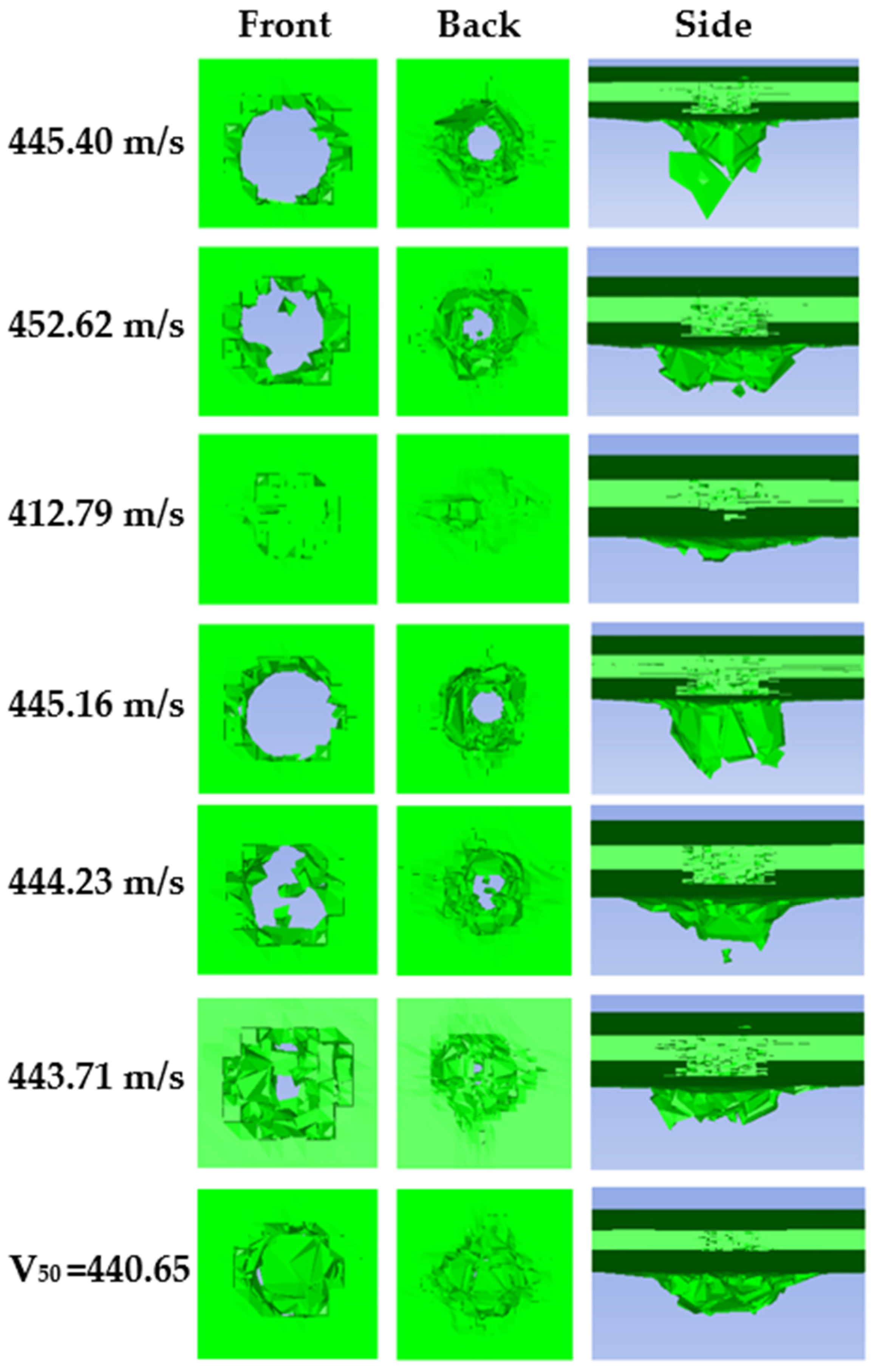
As summarized in Table 3, the numerical simulations predicted three complete penetration events and three partial penetration events. Complete penetration was obtained at impact velocities of 445.40, 452.62, and 445.16 m/s, whereas 412.79, 444.23, and 443.71 m/s resulted in partial penetration.
The corresponding final penetration responses predicted by the numerical simulations are presented in Figure 7, including the front, back, and side views for each impact condition. Complete penetration cases exhibited full projectile perforation through the laminate, producing a continuous damage path across the thickness, whereas partial penetration cases resulted in projectile arrest within the laminate thickness, with damage remaining localized around the impact region. The front views reveal a relatively localized failure zone around the projectile entry point, whereas the back views exhibit a more extensive damaged region associated with damage propagation and rear-face deformation. This asymmetric distribution indicates that material degradation accumulated progressively as the projectile traversed the laminate thickness, producing greater failure toward the exit surface. The side views further illustrate the through-thickness development of material failure and element erosion, highlighting the progressive evolution of damage during projectile penetration. Overall, the predicted damage patterns exhibited the characteristic transition between complete and partial penetration in the vicinity of the predicted ballistic limit.

3.3.1. Damage Evolution and Failure Mechanisms

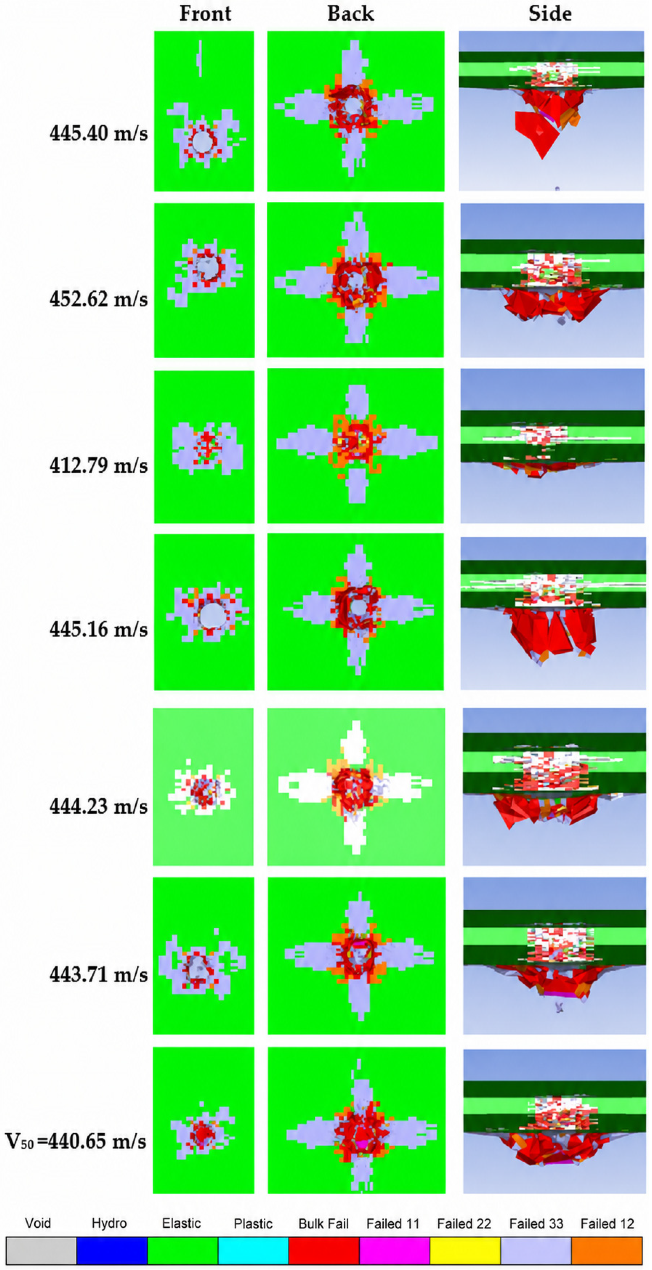
To further investigate the failure mechanisms predicted by the numerical model, the damage distribution was analyzed using the Material Status contours obtained from AUTODYN, as presented in Figure 8. These contours identify the regions where the material satisfied the failure criterion and element erosion occurred, providing a detailed visualization of the spatial distribution of damage following ballistic impact.
The predicted damage remained highly localized around the projectile trajectory for all the impact conditions. Complete penetration cases exhibited a continuous failure path extending across the laminate thickness, whereas partial penetration cases showed localized damage with the projectile arrested before complete perforation. The front views reveal a relatively localized failure zone around the projectile entry point, while the back views exhibit a more extensive damaged region associated with damage propagation and rear-face deformation. This asymmetric distribution indicates that material degradation accumulated progressively as the projectile traversed the laminate thickness, producing greater failure toward the exit surface. The side views illustrate the evolution of through-thickness damage and the extent of element erosion generated during projectile penetration, clearly showing the differences between complete and partial penetration events.
At the predicted ballistic limit (V50 = 440.65 m/s), the damage pattern exhibits characteristics intermediate between complete and partial penetration, representing the transition region where localized material failure develops without a fully established through-thickness failure path. The predicted failure morphology is consistent with the experimental damage observations and provides further insight into the progressive evolution of damage within the aramid/epoxy composite laminate during high-velocity impact.

3.3.2. Energy Evolution During Ballistic Impact

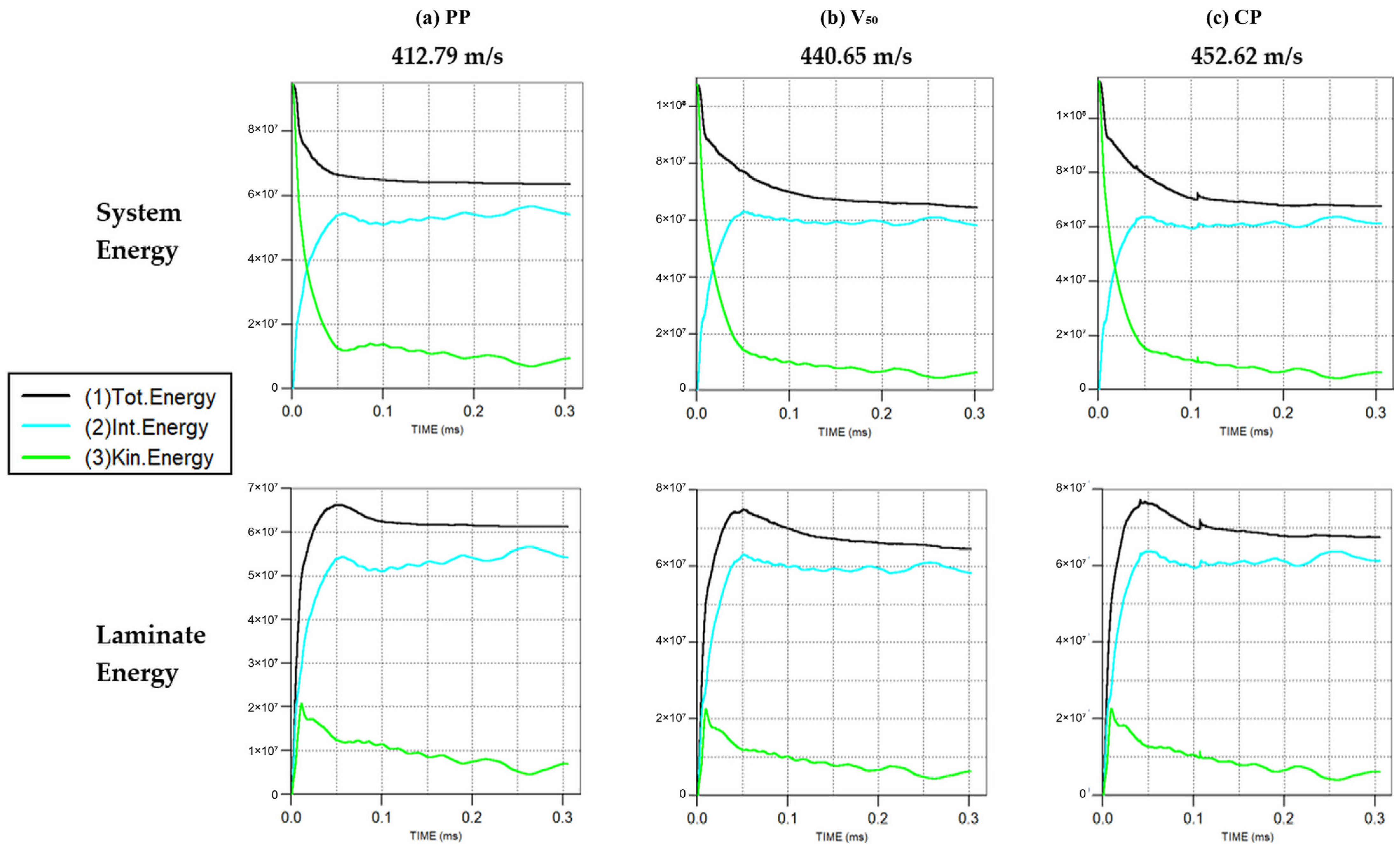
To further examine the energy transfer during ballistic impact, the evolution of the system energy and laminate energy predicted by the numerical simulations was analyzed for three representative impact conditions: partial penetration (PP, 412.79 m/s), the predicted ballistic limit (V50 = 440.65 m/s), and complete penetration (CP, 452.62 m/s), as shown in Figure 9. For all the impact conditions, the total energy remained nearly constant throughout the simulations, with only minor fluctuations observed during the impact event. Immediately after projectile impact, the kinetic energy decreased rapidly as energy was transferred to the composite laminate, while the internal energy increased sharply owing to material deformation and damage development. Following the initial impact stage, the internal energy gradually approached a nearly constant value, whereas the kinetic energy continued to decrease as the impact event progressed. At the ballistic limit (V50), the energy evolution exhibited an intermediate response between the partial and complete penetration cases, reflecting the transition region between projectile arrest and complete perforation.

3.3.3. Projectile Velocity Evolution

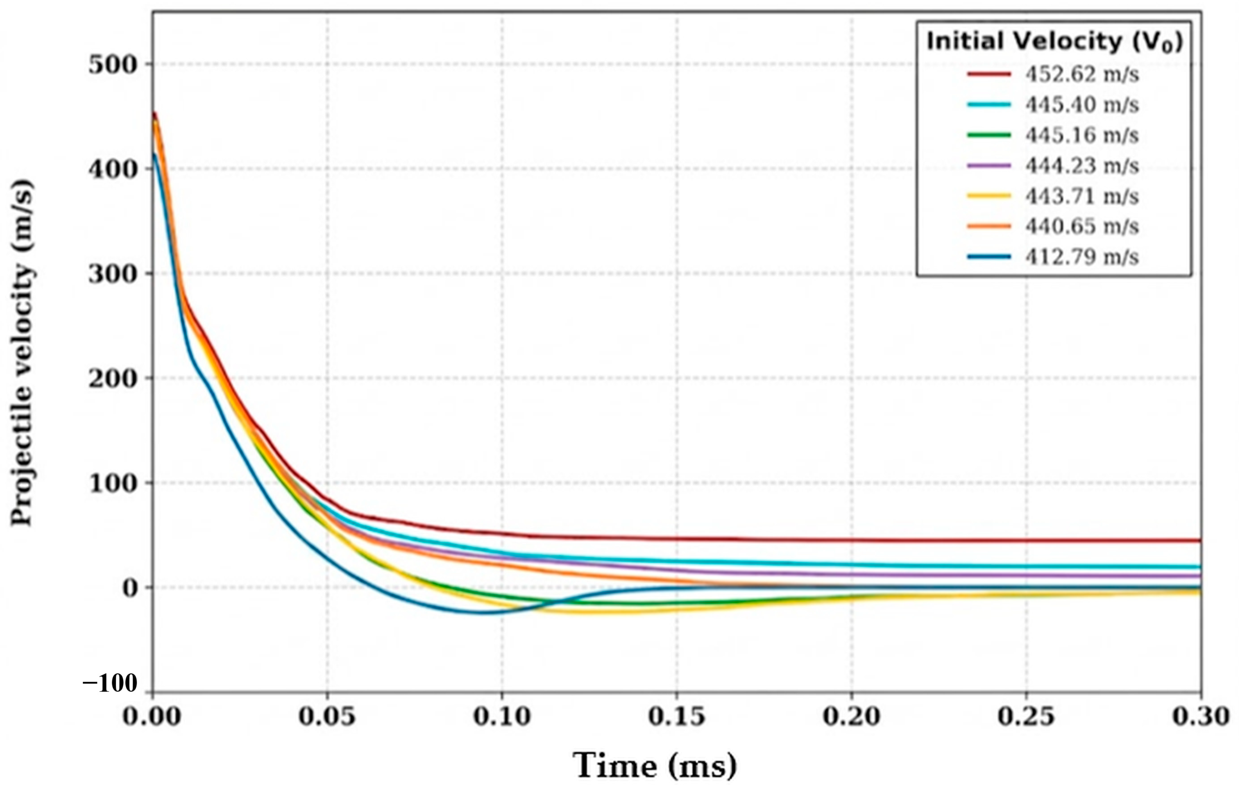
To examine the projectile response during ballistic impact, the velocity histories predicted by the numerical simulations were analyzed for the representative impact conditions corresponding to partial penetration (PP), the ballistic limit (V50), and complete penetration (CP), as presented in Figure 10. In all the cases, the projectile experienced a rapid reduction in velocity immediately after impact, indicating the transfer of kinetic energy to the composite laminate during the initial stage of the impact event. The highest rate of deceleration occurred within the first instants of impact, after which the projectile velocity gradually approached a nearly constant value. For the complete penetration case, the projectile retained a positive residual velocity after perforating the laminate. In contrast, the partial penetration case exhibited a continuous reduction in velocity until reaching values close to zero, followed by a slight reversal in the velocity direction before stabilizing. The velocity history corresponding to the ballistic limit (V50) approached a residual velocity close to zero, representing the transition between the partial and complete penetration responses.

3.4. Comparison Between Experimental and Numerical Results

A direct comparison between the experimental and numerical results was performed to assess the agreement between the observed and predicted penetration responses. The corresponding results are summarized in Table 4. For the six representative impact conditions, the numerical simulations reproduced the experimentally observed penetration response in four cases, whereas two impact conditions exhibited different penetration outcomes. Specifically, discrepancies were observed at impact velocities of 445.16 m/s and 444.23 m/s, while the remaining impact conditions showed identical penetration responses in both the experimental tests and the numerical simulations. Both discrepancies occurred within the ballistic transition region surrounding the ballistic limit (V50), where complete and partial penetration responses may occur under similar impact conditions. The numerical simulations predicted a ballistic limit velocity of V50 = 440.65 m/s, which is in close agreement with the experimental value of 440.57 m/s, corresponding to a relative difference of less than 0.03%.

4. Discussion

The combined experimental and numerical investigation revealed a well-defined transition between partial and complete penetration within the impact velocity range of approximately 412–452 m/s, which is consistent with the ballistic limit criterion established in STANAG 2920 [35]. Within this transition region, relatively small variations in projectile impact velocity produced different penetration responses, indicating that the ballistic performance of the aramid/epoxy laminate is highly sensitive to the balance between the projectile kinetic energy and the energy absorption capability of the composite. Similar transition behavior has been reported for aramid-based composite laminates subjected to high-velocity impact, where the penetration response is governed by the proximity of the impact energy to the critical energy required for complete penetration [6,11,12].
The numerical simulations reproduced the principal characteristics of the experimental ballistic response, including the occurrence of both complete and partial penetration events within the transition region. Direct comparison between the experimental observations and numerical predictions showed agreement for four of the six representative impact conditions, while the two discrepancies occurred at impact velocities located close to the ballistic limit. Such differences are expected within the transition region, where small variations in impact conditions may alter the penetration response. Furthermore, the numerical model predicted a ballistic limit velocity of V50 = 440.65 m/s, which differs by less than 0.03% from the experimentally determined value of 440.57 m/s. Similar levels of agreement between experimental ballistic testing and numerical simulations have been reported for Kevlar-based composite laminates using finite element and hydrocode approaches [10,11,14,24,28].
The numerical results also provided detailed information regarding the damage evolution and energy transfer mechanisms that cannot be directly obtained from ballistic experiments. The Material Status contours showed that material degradation remained localized around the projectile trajectory, with complete penetration cases exhibiting a continuous damage path through the laminate thickness, whereas partial penetration cases remained confined to localized damage with projectile arrest. The predicted energy histories indicated a rapid conversion of projectile kinetic energy into laminate internal energy during the initial stages of impact, while the projectile velocity histories distinguished the characteristic responses associated with partial penetration, the ballistic limit, and complete penetration. These observations are consistent with previous numerical investigations describing progressive damage evolution and energy dissipation in aramid composite laminates subjected to ballistic loading [8,17,21,24].
The close correspondence between the experimental observations and the numerical predictions indicates that the adopted constitutive formulation, together with the implemented stress/strain failure criterion, orthotropic post-failure model, and instantaneous geometric strain erosion algorithm, adequately represented the global ballistic response of the investigated laminate under Fragment Simulating Projectile (FSP) impact. Similar constitutive modeling strategies have been successfully employed for ballistic simulations of Kevlar composite laminates and protective structures [17,19,21,24,28]. Consequently, the proposed methodology provides a practical numerical framework for evaluating the ballistic performance of non-commercial aramid/epoxy composite laminates during the preliminary design stage, reducing the number of experimental trials required for ballistic characterization.
Future work should focus on incorporating advanced progressive damage formulations and interlaminar failure models capable of explicitly representing delamination, matrix cracking, and fiber pull-out, thereby improving the prediction of localized failure mechanisms during high-velocity impact [18,25].

5. Conclusions

The ballistic performance of a 28-layer non-commercial aramid/epoxy composite laminate subjected to Fragment Simulating Projectile (FSP) impact was investigated through combined experimental testing and numerical simulations using ANSYS® AUTODYN. Based on the obtained results, the following conclusions can be drawn:
The experimental ballistic limit velocity of the investigated laminate was determined as V50 = 440.57 m/s, while the numerical model predicted V50 = 440.65 m/s, corresponding to a relative difference of less than 0.03%.
Both the experimental tests and numerical simulations identified a well-defined transition region between partial and complete penetration. The numerical model reproduced the penetration response for four of the six representative impact conditions, whereas the remaining discrepancies occurred within the ballistic transition region surrounding the ballistic limit.
The numerical simulations successfully reproduced the principal features of the ballistic impact process, including the progressive damage evolution, through-thickness failure, projectile velocity evolution, and the transfer of kinetic energy into laminate internal energy for partial penetration, ballistic limit, and complete penetration conditions.
The adopted constitutive formulation implemented in AUTODYN, together with the selected failure criterion and post-failure modeling strategy, provided an accurate prediction of the global ballistic response of the investigated aramid/epoxy laminate under standardized FSP impact conditions.
In addition to providing experimental ballistic performance data for a non-commercial aramid/epoxy composite laminate manufactured by the vacuum bag process, this study establishes a validated experimental–numerical methodology that can be applied to the evaluation and preliminary design of lightweight composite armor systems, reducing the extent of experimental testing required during ballistic characterization and optimization.

Author Contributions

Conceptualization, H.R.M.-P.d.L., O.S.-H. and N.L.-P.; methodology, H.R.M.-P.d.L. and C.A.E.-D.; software, C.A.E.-D., M.R.M. and H.R.M.-P.d.L.; validation, M.R.M., H.R.M.-P.d.L. and C.A.E.-D.; formal analysis, M.R.M. and C.A.E.-D.; investigation, C.A.E.-D., O.S.-H. and M.A.D.-R.; resources, N.L.-P., O.S.-H. and M.A.D.-R.; data curation, C.A.E.-D. and M.R.M.; writing—original draft preparation, C.A.E.-D.; writing—review and editing, H.R.M.-P.d.L., O.S.-H. and M.R.M.; visualization, M.A.D.-R., C.A.E.-D. and N.L.-P.; supervision, O.S.-H. and H.R.M.-P.d.L.; project administration, N.L.-P. and M.A.D.-R. All authors have read and agreed to the published version of the manuscript.

Funding

This research received no external funding.

Data Availability Statement

The raw data supporting the conclusions of this article will be made available by the authors on request.

Acknowledgments

The authors would like to acknowledge FECSA for its support in conducting the ballistic impact tests at the company’s facilities.

Conflicts of Interest

The authors declare no conflict of interest. While the authors acknowledge FECSA for providing facilities and technical support for the ballistic impact tests, this support did not influence the study design, data collection, analysis, interpretation, manuscript preparation, or the decision to publish the results.

Abbreviations

The following abbreviations are used in this manuscript:
CPComplete Penetration
FEMFinite Element Method
FSPFragment Simulating Projectile
GFRPGlass Fiber Reinforced Polymer
NOMOfficial Mexican Norm
PPPartial Penetration
SMAShape Memory Alloy
STANAGStandardization Agreement
V50Ballistic Limit Velocity

References

  1. Naik, N.K.; Shrirao, P. Composite structures under ballistic impact. Compos. Struct. 2004, 66, 579–590. [Google Scholar] [CrossRef]
  2. Bhat, A.; Naveen, J.; Jawaid, M.; Norrrahim, M.N.F.; Rashedi, A.; Khan, A. Advancement in fiber reinforced polymer, metal alloys and multi-layered armour systems for ballistic applications—A review. J. Mater. Res. Technol. 2021, 15, 1300–1317. [Google Scholar] [CrossRef]
  3. Rana, K.; Sajid, Z.; Baluch, A.H.; Špatenka, P. Aramid fibre composites for ballistic impact protection: A mechanistic review of recent advances. Appl. Compos. Mater. 2026, 33, 103. [Google Scholar] [CrossRef]
  4. Kim, G.; Cho, Y.Y.; Lee, M.Y.; Prasad, C.; Munagapati, V.S.; Wen, J.-C.; Choi, H.Y.; Won, J.S. Progress and prospects of Kevlar–epoxy composites: The next generation materials for bulletproof and body armor applications. Compos. Part B Eng. 2026, 324, 113906. [Google Scholar] [CrossRef]
  5. Espinosa Dominguez, C.A.; Ortiz Hernández, H.; Mollinedo, H.; Susarrey Huerta, O.; Hernández Moreno, H. Development and physical characterization of a composite laminate aramid/epoxy manufactured by the vacuum bag method. Polym. Korea 2023, 47, 108–115. [Google Scholar] [CrossRef]
  6. Zhu, G.; Goldsmith, W.; Dharan, C.K.H. Penetration of laminated Kevlar by projectiles—I. Experimental investigation. Int. J. Solids Struct. 1992, 29, 399–420. [Google Scholar] [CrossRef]
  7. Lee, B.L.; Song, J.W.; Ward, J.E. Failure of Spectra® polyethylene fiber-reinforced composites under ballistic impact loading. J. Compos. Mater. 1994, 28, 1202–1226. [Google Scholar] [CrossRef]
  8. Silva, M.A.G.; Cismașiu, C.; Chiorean, C.G. Numerical simulation of ballistic impact on composite laminates. Int. J. Impact Eng. 2005, 31, 289–306. [Google Scholar] [CrossRef]
  9. Kumar, S.; Gupta, D.S.; Singh, I.; Sharma, A. Behavior of Kevlar/epoxy composite plates under ballistic impact. J. Reinf. Plast. Compos. 2010, 29, 2048–2064. [Google Scholar] [CrossRef]
  10. Bresciani, L.M.; Manes, A.; Ruggiero, A.; Iannitti, G.; Giglio, M. Experimental tests and numerical modelling of ballistic impacts against Kevlar® 29 plain-woven fabrics with an epoxy matrix: Macro-homogeneous and meso-heterogeneous approaches. Compos. Part B Eng. 2016, 88, 114–130. [Google Scholar] [CrossRef]
  11. Gonçalves Nunes, S.; Scazzosi, R.; Manes, A.; Amico, S.C.; Ferreira de Amorim Júnior, W.; Giglio, M. Influence of projectile and thickness on the ballistic behavior of aramid composites: Experimental and numerical study. Int. J. Impact Eng. 2019, 132, 103307. [Google Scholar] [CrossRef]
  12. Ramadhan, A.A.; Abu Talib, A.R.; Mohd Rafie, A.S.; Zahari, R. High velocity impact response of Kevlar-29/epoxy and 6061-T6 aluminum laminated panels. Mater. Des. 2013, 43, 307–321. [Google Scholar] [CrossRef]
  13. Bandaru, A.K.; Chavan, V.V.; Ahmad, S.; Alagirusamy, R.; Bhatnagar, N. Ballistic impact response of Kevlar® reinforced thermoplastic composite armors. Int. J. Impact Eng. 2016, 89, 1–13. [Google Scholar] [CrossRef]
  14. Biswas, K.; Datta, D. Experimental and numerical analysis of ballistic impact and material characterization of GFRP and Kevlar 29/epoxy composite laminate. Proc. Inst. Mech. Eng. Part L J. Mater. Des. Appl. 2025, 239, 603–616. [Google Scholar] [CrossRef]
  15. Anderson, C.E., Jr. An overview of the theory of hydrocodes. Int. J. Impact Eng. 1987, 5, 33–59. [Google Scholar] [CrossRef]
  16. Anderson, C.E., Jr.; Cox, P.A.; Johnson, G.R.; Maudlin, P.J. A constitutive formulation for anisotropic materials suitable for wave propagation computer programs—II. Comput. Mech. 1994, 15, 201–223. [Google Scholar] [CrossRef]
  17. Hayhurst, C.J.; Hiermaier, S.J.; Clegg, R.A.; Riedel, W.; Lambert, M. Development of material models for Nextel and Kevlar-epoxy for high pressures and strain rates. Int. J. Impact Eng. 1999, 23, 365–376. [Google Scholar] [CrossRef]
  18. van Hoof, J. Modelling of Impact Induced Delamination in Composite Materials. Ph.D. Thesis, Carleton University, Ottawa, ON, Canada, 1999. [Google Scholar]
  19. Hayhurst, C.J.; Livingstone, I.H.G.; Clegg, R.A.; Destefanis, R.; Faraud, M. Ballistic limit evaluation of advanced shielding using numerical simulations. Int. J. Impact Eng. 2001, 26, 309–320. [Google Scholar] [CrossRef]
  20. Clegg, R.A.; White, D.M.; Riedel, W.; Harwick, W. Hypervelocity impact damage prediction in composites: Part I—Material model and characterisation. Int. J. Impact Eng. 2006, 33, 190–200. [Google Scholar] [CrossRef]
  21. Liu, T.; Zhang, X.-T.; He, N.-B.; Jia, G.-H. Numerical material model for composite laminates in high-velocity impact simulation. Lat. Am. J. Solids Struct. 2017, 14, 1912–1931. [Google Scholar] [CrossRef][Green Version]
  22. Gower, H.L.; Cronin, D.S.; Plumtree, A. Ballistic impact response of laminated composite panels. Int. J. Impact Eng. 2008, 35, 1000–1008. [Google Scholar] [CrossRef]
  23. Ahn, J.-H.; Nguyen, K.-H.; Park, Y.-B.; Kweon, J.-H.; Choi, J.-H. A numerical study of the high-velocity impact response of a composite laminate using LS-DYNA. Int. J. Aeronaut. Space Sci. 2010, 11, 221–226. [Google Scholar] [CrossRef]
  24. Rodríguez-Millán, M.; Moreno, C.E.; Marco, M.; Santiuste, C.; Miguélez, M.H. Numerical analysis of the ballistic behaviour of Kevlar® composite under impact of double-nosed stepped cylindrical projectiles. J. Reinf. Plast. Compos. 2016, 35, 124–137. [Google Scholar] [CrossRef]
  25. Roszak, M.; Stępczak, M.; Kazimierczak, M.; Jamroziak, K. Finite element method modeling strategies for fiber-based ballistic composites: From discrete fiber models to digital twins of fabrics. Arch. Comput. Methods Eng. 2026; advance online publication. [CrossRef]
  26. Tham, C.Y.; Tan, V.B.C.; Lee, H.P. Ballistic impact of a Kevlar® helmet: Experiment and simulations. Int. J. Impact Eng. 2008, 35, 304–318. [Google Scholar] [CrossRef]
  27. Lee, H.P.; Gong, S.W. Finite element analysis for the evaluation of protective functions of helmets against ballistic impact. Comput. Methods Biomech. Biomed. Eng. 2010, 13, 537–550. [Google Scholar] [CrossRef] [PubMed]
  28. Rodríguez-Millán, M.; Ito, T.; Loya, J.A.; Olmedo, A.; Miguélez, M.H. Development of numerical model for ballistic resistance evaluation of combat helmet and experimental validation. Mater. Des. 2016, 110, 391–403. [Google Scholar] [CrossRef]
  29. Rubio, I.; Rodríguez-Millán, M.; Marco, M.; Olmedo, A.; Loya, J.A. Ballistic performance of aramid composite combat helmet for protection against small projectiles. Compos. Struct. 2019, 226, 111153. [Google Scholar] [CrossRef]
  30. Hong, H.; Qiu, C.; d’Apolito, L.; Yang, Y. Impact energy absorption numerical analysis and structural optimization of lightweight composite ballistic helmet. Fibers Polym. 2026, 27, 2383–2407. [Google Scholar] [CrossRef]
  31. Bandaru, A.K.; Vetiyatil, L.; Ahmad, S. The effect of hybridization on the ballistic impact behavior of hybrid composite armors. Compos. Part B Eng. 2015, 76, 300–319. [Google Scholar] [CrossRef]
  32. Gregori, D.; Scazzosi, R.; Nunes, S.G.; Amico, S.C.; Giglio, M.; Manes, A. Analytical and numerical modelling of high-velocity impact on multilayer alumina/aramid fiber composite ballistic shields: Improvement in modelling approaches. Compos. Part B Eng. 2020, 187, 107830. [Google Scholar] [CrossRef]
  33. Ravindran, P.; Kumar, K.M.; Rangasamy, S.; Vijaya Kumar, K.R. Experimental and numerical investigation of ballistic impact analysis on Kevlar reinforced polymer composites and shape memory alloy sheet reinforced Kevlar epoxy polymer composites. Polym. Korea 2022, 46, 470–475. [Google Scholar] [CrossRef]
  34. Leiva Palomera, D.F.; Fernández Abreu, M.E.; Valín Rivera, J.L.; Valin Fernández, M.; Ferreira de Amorim Júnior, W.; Valenzuela Diaz, F.R.; Alcaino Molina, D.A.; Mendez Jofre, P.E.; Ketterer, C.I.G. Analysis of the ballistic effectiveness of the hybrid composite of polyurethane and Kevlar 29 with different grammages. Polymers 2025, 17, 372. [Google Scholar] [CrossRef] [PubMed]
  35. NATO Standardization Agency. STANAG 2920: Ballistic Test Method for Personal Armour Materials and Combat Clothing; NATO Standardization Agency: Brussels, Belgium, 2003. [Google Scholar]
  36. Secretaría de Comercio y Fomento Industrial. NOM-142-SCFI-2000, Niveles de Protección de Materiales para Blindajes Resistentes a Impactos Balísticos—Especificaciones de Seguridad y Métodos de Prueba; Diario Oficial de la Federación: Ciudad de México, México, 2000. [Google Scholar]
Figure 1. Finite element model of the aramid/epoxy laminate showing the structured mesh and constrained boundary nodes. The black regions correspond to areas of high mesh-line density resulting from local mesh refinement.The dark green diamond markers indicate the boundary nodes constrained using the General 3D Velocity boundary condition.
Jcs 10 00413 g001
Figure 2. Geometry and finite element discretization of the Fragment Simulating Projectile (FSP): (a) dimensional sketch, (b) CAD model, and (c) finite element mesh. The colors shown are default visualization settings of the software and do not represent different materials or physical properties.
Jcs 10 00413 g002
Figure 3. Clamping fixture employed for ballistic impact testing of the composite laminates.
Jcs 10 00413 g003
Figure 4. Front-face damage morphology of the aramid/epoxy composite laminates after impact with Fragment Simulating Projectiles (FSPs): (a) 445.40 m/s (CP), (b) 452.62 m/s (CP), (c) 412.79 m/s (PP), (d) 445.16 m/s (PP), (e) 444.23 m/s (CP), and (f) 443.71 m/s (PP).
Jcs 10 00413 g004
Figure 5. Rear-face damage morphology of the aramid/epoxy composite laminates after impact with Fragment Simulating Projectiles (FSPs): (a) 445.40 m/s (CP), (b) 452.62 m/s (CP), (c) 412.79 m/s (PP), (d) 445.16 m/s (PP), (e) 444.23 m/s (CP), and (f) 443.71 m/s (PP).
Jcs 10 00413 g005
Figure 6. Time evolution of the numerical simulation of a 0.22 caliber Fragment Simulating Projectile (FSP) impacting the aramid/epoxy composite laminate at an impact velocity of 445.40 m/s, showing (a) initial projectile position (0 ms), (b) initial contact and onset of penetration (0.1 ms), (c) progressive penetration and damage development (0.2 ms), and (d) complete perforation of the laminate (0.3 ms).
Jcs 10 00413 g006
Figure 7. Final penetration responses predicted by the numerical simulations for the six impact velocities used in the ballistic assessment and the predicted ballistic limit (V50 = 440.65 m/s). Front, back, and side views illustrate the damage morphology and through-thickness response of the aramid/epoxy composite laminate, highlighting the transition between complete and partial penetration. The colors are default AUTODYN visualization settings.
Jcs 10 00413 g007
Figure 8. Material Status contours predicted by the numerical simulations for the six impact velocities and the predicted ballistic limit (V50 = 440.65 m/s). Front, back, and side views illustrate the spatial distribution of material failure and element erosion within the aramid/epoxy composite laminate after ballistic impact. Complete penetration cases exhibit a continuous failure path through the laminate thickness, whereas partial penetration cases show localized damage associated with projectile arrest.
Jcs 10 00413 g008
Figure 9. Evolution of the system energy (top row) and laminate energy (bottom row) predicted by the numerical simulations for three representative impact conditions: (a) partial penetration (PP, 412.79 m/s), (b) ballistic limit (V50 = 440.65 m/s), and (c) complete penetration (CP, 452.62 m/s). The curves show the evolution of total, internal, and kinetic energies during ballistic impact, illustrating the progressive transfer of projectile kinetic energy into internal energy and the corresponding energy absorption of the aramid/epoxy composite laminate.
Jcs 10 00413 g009
Figure 10. Projectile velocity histories predicted by the numerical simulations for the six experimental impact velocities and the predicted ballistic limit (V50 = 440.65 m/s). Positive residual velocities indicate complete penetration, whereas velocities approaching zero or exhibiting a slight negative value correspond to projectile arrest and partial penetration.
Jcs 10 00413 g010
Table 1. Material model parameters of the aramid/epoxy composite laminate implemented in ANSYS® AUTODYN [9,13,26].
ParameterValue
Equation of stateOrthotropic
Reference density (g/cm3)1.17
Young’s modulus 11 (kPa)1.799 × 10⁷
Young’s modulus 22 (kPa)1.799 × 10⁷
Young’s modulus 33 (kPa)1.948 × 10⁶
Poisson ratio 120.08
Poisson ratio 230.698
Poisson ratio 310.0756
Shear modulus 12 (kPa)7.70 × 10⁵
Shear modulus 23 (kPa)1.857 × 10⁶
Shear modulus 31 (kPa)1.857 × 10⁶
Strength modelElastic
Failure modelMaterial stress/strain
Tensile failure stress 11 (kPa)1.85 × 10⁶
Tensile failure stress 22 (kPa)1.85 × 10⁶
Tensile failure stress 33 (kPa)1.20 × 10⁶
Maximum shear stress 12 (kPa)7.70 × 10⁴
Maximum shear stress 23 (kPa)5.43 × 10⁵
Maximum shear stress 31 (kPa)5.43 × 10⁵
Tensile failure strain 110.06
Tensile failure strain 220.06
Tensile failure strain 330.02
Maximum shear strain 121.01 × 10²⁰
Maximum shear strain 231.01 × 10²⁰
Maximum shear strain 311.01 × 10²⁰
Post-failure optionOrthotropic
Residual shear stiffness fraction0.2
Erosion criterionGeometric strain
Erosion strain1.4
Geometric strain typeInstantaneous
Table 2. Experimental ballistic impact results obtained using FSPs.
ShotImpact Velocity (m/s)Penetration
1445.40Complete
2452.16Complete
3412.79Partial
4445.16Partial
5444.23Complete
6443.71Partial
Table 3. Numerical penetration responses.
ShotInitial Velocity (m/s)Penetration
1445.40Complete
2452.62Complete
3412.79Partial
4445.16Complete
5444.23Partial
6443.71Partial
Table 4. Comparison between experimental and numerical penetration responses for the representative impact conditions.
ShotImpact
Velocity (m/s)
Experimental
Response
Numerical
Response
Agreement
1445.40CompleteComplete
2452.62CompleteComplete
3412.79PartialPartial
4445.16PartialComplete
5444.23CompletePartial
6443.71PartialPartial
Note: ✓ indicates agreement between the experimental and numerical penetration responses, whereas ✗ indicates disagreement.
Disclaimer/Publisher’s Note: The statements, opinions and data contained in all publications are solely those of the individual author(s) and contributor(s) and not of MDPI and/or the editor(s). MDPI and/or the editor(s) disclaim responsibility for any injury to people or property resulting from any ideas, methods, instructions or products referred to in the content.