Article

LT-UVAM Milling of Thin Cellular Structures: Chip Fragmentation and Machinability

1
LAMOEE, Équipe de Mécanique, Thermique, Énergie Renouvelable et Efficacité Énergétique, Faculté des Sciences Oujda, Oujda 60000, Morocco
2
Department of Pure and Applied Mathematics, Saveetha School of Engineering, SIMATS, Chennai 602105, Tamil Nadu, India
3
Laboratory of Energetics (LE), Faculty of Sciences, Abdelmalek Essaadi University, Tetouan 93000, Morocco
4
Laboratoire d’Energétique et de Mécanique Théorique et Appliquée, Ecole des Mines de Nancy, Université de Lorraine, F-88100 Saint Dié Des Vosges, France
5
College of Mechanical and Electrical Engineering, Nanjing University of Aeronautics and Astronautics, Nanjing 210016, China
*
Author to whom correspondence should be addressed.
J. Compos. Sci. 2026, 10(8), 387; https://doi.org/10.3390/jcs10080387
Submission received: 20 June 2026 / Revised: 23 July 2026 / Accepted: 24 July 2026 / Published: 26 July 2026
(This article belongs to the Special Issue Manufacturing and Machining of Composites)

Abstract

Aluminum honeycomb structures are widely used in the aeronautical, aerospace, marine, and automotive industries due to their excellent stiffness-to-weight ratio. However, machining these structures remains highly challenging because their thin, highly flexible cell walls are susceptible to plastic deformation and geometric defects. To overcome these limitations, this study proposes an innovative machining approach that combines longitudinal-torsional ultrasonic vibration-assisted machining (LT-UVAM) with a 55-tooth CZD10 cutting tool. A three-dimensional finite element model was developed using Abaqus/Explicit 2017 to simulate the dynamic interactions between the cutting tool and the honeycomb cell walls during the milling process. Following experimental validation on a high-speed machining center, the model was employed to investigate the effects of cutting and vibration parameters on the machining performance. The results demonstrate that longitudinal-torsional ultrasonic vibration coupling significantly reduces the cutting forces, resulting in a 26% to 42% reduction in the axial force component (Fz). Furthermore, vibration assistance effectively limits cell wall deflection, reducing the stress levels by up to 60% in the thinnest walls while maintaining them below the critical Euler buckling load. Furthermore, an ultrasonic vibration frequency of 22.5 kHz almost completely eliminates plastic deformation, while a vibration amplitude of 25 µm significantly reduces tool wear by promoting intermittent tool–workpiece contact, thereby facilitating chip evacuation. Ultimately, the LT-UVAM process produces finer and more uniform chips, leading to improved machining quality, enhanced dimensional accuracy, and extended tool life.

1. Introduction

Sandwich composite structures with aluminum honeycomb cores are among the most widely used solutions in high-tech industries, particularly in the automotive, aerospace, and space sectors [1,2]. Their outstanding specific properties, combining exceptional lightweight characteristics with high stiffness and superior strength-to-weight ratios, make them ideal for critical structural applications, including aircraft wings and fins, helicopter rotor blades, and support structures for satellite solar arrays [3,4,5,6,7]. These exceptional properties are directly attributed to the unique geometric architecture of the honeycomb core. Sandwiched between two thin, rigid face sheets, the core optimizes stress distribution and provides superior structural stability compared with conventional monolithic materials under demanding service conditions. However, the widespread industrial adoption of these structures remains constrained by manufacturing challenges. In particular, defects generated during trimming operations necessitate ultra-high-precision machining to ensure the required dimensional accuracy and structural integrity [8]. Furthermore, the inherent flexibility of the thin cell walls makes them highly susceptible to plastic deformation and persistent burr formation [9,10,11]. To overcome their insufficient transient stiffness, several innovative approaches, such as temporary core stiffening through cryogenic freezing, have been proposed to stabilize the cell walls and reduce machining-induced vibrations [12]. In this context, the studies conducted by Wang et al. [13,14] on cryogenic milling following core solidification demonstrated a significant reduction in geometric surface defects, thereby confirming the effectiveness of this approach. These investigations also laid the foundation for subsequent research aimed at elucidating the fundamental mechanisms of chip fragmentation and the local interaction dynamics between the cutting edge and the honeycomb cell walls [15]. In parallel, the authors investigated the mechanical stresses generated during the trimming of aluminum honeycomb structures by examining the coupled effects of the cutting parameters, including cutting speed, feed rate, and depth of cut. Their findings, supported by a rigorous correlation between analytical modeling and experimental validation, highlighted the predominant influence of the honeycomb topology, particularly its cell density and orientation, on both the dynamic stability of the machining process and the geometric accuracy of the machined components [5]. Meanwhile, the numerical model developed by Zarrouk et al. [16] focused on simulating the conventional milling of aluminum honeycomb structures. The three-dimensional models developed by the authors enable accurate prediction of the cutting forces and capture the deformation of the aluminum cell walls during machining. Their findings confirm the significant influence of kinematic and geometric parameters on machining performance while emphasizing the need for highly accurate numerical models to minimize manufacturing defects. However, conventional machining techniques still exhibit inherent limitations, leading to high cutting forces and poor surface quality, even when optimized toolpaths are employed. To address these limitations, ultrasonic vibration-assisted machining has emerged as a promising alternative. By superimposing high-frequency ultrasonic vibrations onto the tool motion, this process reduces the average cutting forces and improves surface quality. Numerous experimental studies have demonstrated the advantages of ultrasonic vibration-assisted machining for processing difficult-to-machine materials, including lightweight alloys and advanced composite materials. In this context, Sun et al. [17] investigated the wall deformation mechanisms during the ultrasonic cutting of an aluminum honeycomb core using a straight-blade tool. By employing a finite element model (FEM) validated against experimental data, they demonstrated that appropriate adjustment of the blade inclination angle and vibration amplitude effectively controls cell wall deflection. Kuo et al. [18] investigated the interactions among tool geometry, cutting speed, and ultrasonic vibration assistance during the trimming of glass-fiber honeycomb cores. Their results indicate that ultrasonic vibration assistance effectively suppresses microcrack formation, whereas excessively high cutting speeds promote internal damage. Furthermore, although helical cutting tools exhibit lower wear than straight tools, an inappropriate combination of cutting speed and vibration amplitude may result in significant localized damage. Consequently, ultrasonic cutting has emerged as a highly effective technique for reducing cutting resistance and minimizing macroscopic defects [19]. This process, which combines the rotary motion of the cutting tool with longitudinal ultrasonic vibrations, has been successfully validated in several previous studies [20]. The combination of numerical simulations and experimental investigations has confirmed its effectiveness in preserving the geometric integrity of the hexagonal cells. Nevertheless, the existing literature has primarily focused on macroscopic phenomena, while largely overlooking the microscopic tearing and shearing mechanisms occurring within the honeycomb cell walls. Comprehensive studies on hybrid ultrasonic vibration-assisted machining (HUSVAM) of aluminum honeycomb structures remain limited, particularly with regard to fundamental aspects such as chip accumulation mechanisms, the evolution of the three-dimensional components of the cutting forces, and the surface topography of the machined components. Traditionally, the optimization of these machining processes has relied on extensive and costly experimental campaigns. However, numerical modeling now provides an efficient and cost-effective alternative by enabling the investigation of a wide range of operating conditions [21]. Despite its promising potential, the machining of aluminum honeycomb cores using hybrid ultrasonic vibration-assisted machining (HUSVAM) has not yet been thoroughly investigated, particularly with respect to the prediction of three-dimensional stress distributions, tool–workpiece contact interactions, surface integrity, and edge-related damage mechanisms. To address this gap in the literature, the present study proposes an innovative approach that extends beyond conventional formulations by accurately modeling the three-dimensional kinematics induced by the coupled longitudinal-torsional ultrasonic vibrations of a 55-tooth cutting tool. The primary objective of this study is to address the scientific challenges associated with local microscopic chip formation mechanisms and thin-walled cell buckling, two aspects that have been largely overlooked in favor of macroscopic analyses. To this end, an advanced three-dimensional finite element model was developed and rigorously validated through high-speed machining experiments on 5056 aluminum alloy honeycomb structures. In addition to providing a detailed analysis of chip morphology and adhesive tool wear, this study establishes a predictive framework for the development of a digital twin. Ultimately, the proposed approach has the potential to be extended to other complex cellular structures and to serve as a robust optimization tool for the large-scale industrial manufacturing of next-generation lightweight components.

2. Materials and Methods

2.1. Geometric Characteristics of the Cutting Tool and Description of the Alveolar Structure Studied

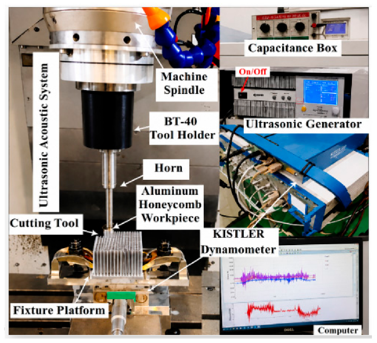
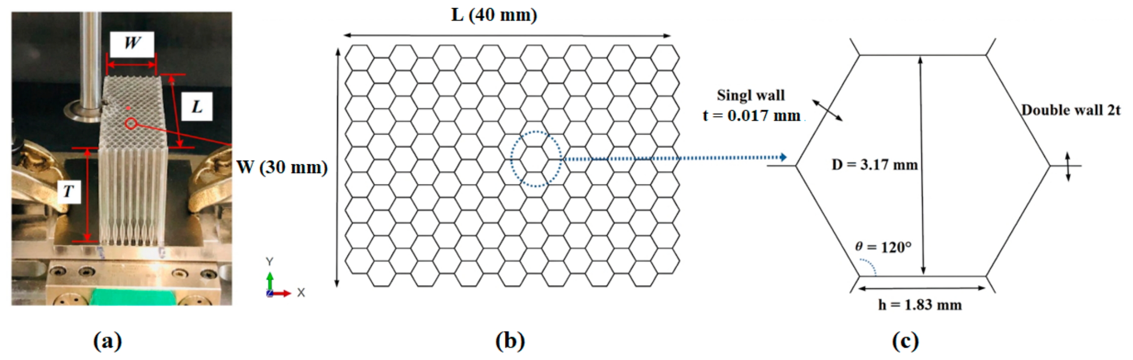
To investigate the machining behavior of metallic honeycomb structures, an experimental campaign was conducted on 5056 aluminum honeycomb panels, which are widely used in high-tech industries because of their excellent strength-to-weight ratio. The cutting experiments were carried out on a RÖDERS RXP 600 high-speed machining center (RÖDERS GmbH, Soltau, Germany) high-speed machining center, selected for its superior dynamic performance, structural rigidity, and high positioning accuracy. This experimental platform enabled the accurate reproduction of industrial machining conditions while ensuring precise control of the operating parameters. All experiments were performed in accordance with the experimental protocols established at the University of Lorraine (Nancy, France), thereby ensuring the reliability, repeatability, and relevance of the acquired data for analyzing the machining mechanisms of honeycomb structures (Figure 1) [22]. The experimental setup consisted of an integrated ultrasonic machining system specifically designed to investigate cutting mechanisms under ultrasonic vibration assistance. The system included a BP4610 ultrasonic generator equipped with a fast-bipolar power supply and a high-frequency compensation capacitor to ensure stable and efficient excitation. Ultrasonic vibrations were transmitted to the cutting tool through an ultrasonic spindle fitted with a BT40 tool holder, thereby ensuring efficient transmission of vibrational energy to the cutting zone. The machining forces were measured using a Kistler 9129AA piezoelectric dynamometer, which enabled the accurate acquisition of the three-dimensional cutting force components. The workpiece was secured using a custom-designed clamping system to ensure its stability throughout the machining process, while all operating parameters were controlled by the machine tool’s numerical control (CNC) system. To organize the experimental campaign efficiently while limiting the number of machining trials, a Taguchi L27 orthogonal array was adopted. Six control factors were investigated at three levels, allowing a systematic and balanced exploration of the machining parameter space with a substantially reduced number of experiments compared with a full factorial design. Each experimental condition was repeated three times to assess measurement repeatability and improve the reliability of the experimental data. In the present work, the Taguchi design was used exclusively to define the experimental matrix. The statistical analyses typically associated with this approach, such as the signal-to-noise ratio (SNR) and analysis of variance (ANOVA), are beyond the scope of this study and are therefore not presented, as the focus is placed on the experimental observations and their correlation with the finite element simulations. The machined surfaces were characterized using advanced metrology techniques to provide a multiscale assessment of surface integrity. Surface topography and three-dimensional roughness parameters were measured using a 3D optical profilometer, whereas damage mechanisms, morphological defects, and material adhesion phenomena were examined with a high-resolution Quanta 650 FEG scanning electron microscope (SEM). The experimental investigations were carried out on 5056 aluminum honeycomb structures with a low nominal density of 49 kg/m3, providing an excellent stiffness-to-weight ratio. The specimens consisted of a regular honeycomb network comprising ten rows of cells across the width and nineteen rows along the length. The overall mechanical performance of this architecture is governed by the hexagonal cell geometry, whose geometric characteristics determine the stress distribution, energy absorption capacity, and apparent density. The principal geometric parameters of the investigated honeycomb structure are presented in Figure 2.
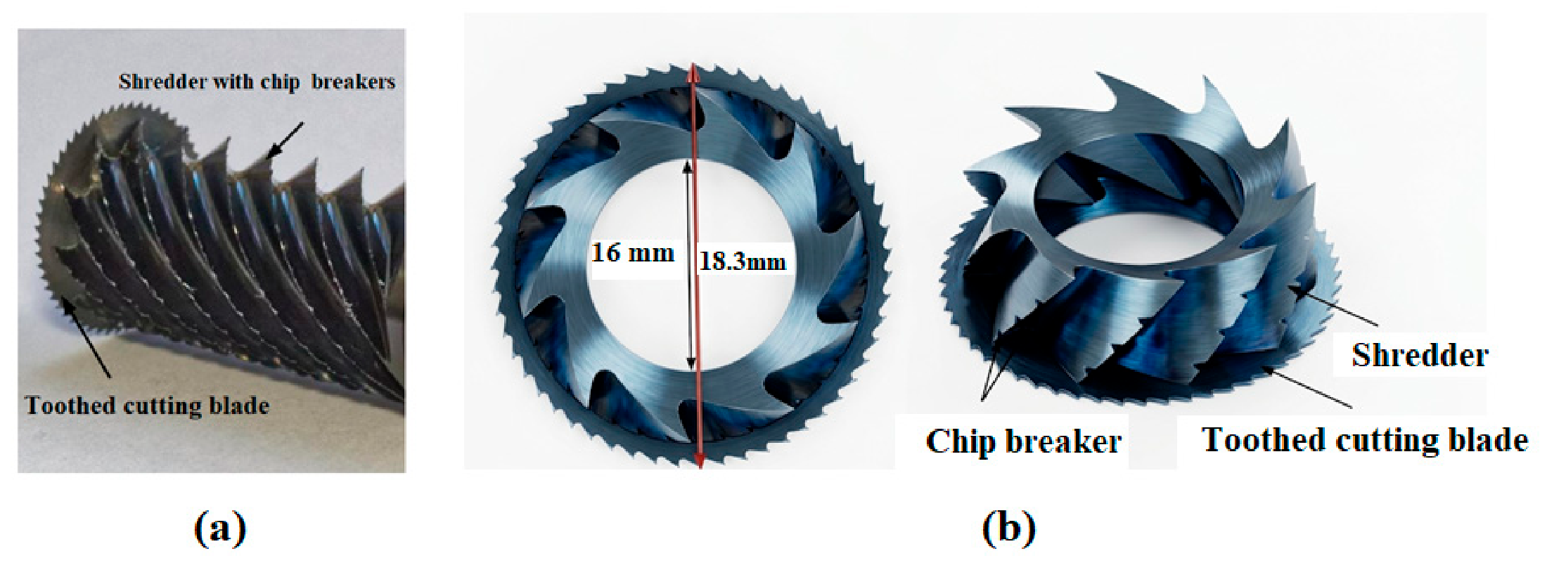
Aluminum honeycomb structures are widely used in aerospace applications because of their low density and outstanding mechanical performance. However, machining these structures remains highly challenging owing to the thin cell walls and the stringent requirements for dimensional accuracy and surface integrity. In this context, cutting tool selection plays a critical role in ensuring process stability, minimizing local deformation, and achieving high-quality machined surfaces. The experimental investigations were carried out using a dedicated CZD10 cutting tool designed and manufactured by EVATEC Tools [22]. This tool was specifically developed for the routing and finishing of metallic honeycomb structures. It consists of a cylindrical cutter with a diameter of 16 mm incorporating ten chip-breaking flutes to facilitate chip evacuation and reduce cutting forces. The assembly also includes a conical cutting disc fitted with tungsten carbide inserts, having an outer diameter of 18.3 mm and fifty-five teeth uniformly distributed around its circumference. The cutting geometry is defined by a zero-rake angle and a clearance angle of 2.5°, providing an optimal balance between machining stability, tool life, and machining quality. The principal geometric characteristics of the CZD10 cutting tool are presented in Figure 3.

2.2. Description of Experimental and Numerical Approaches

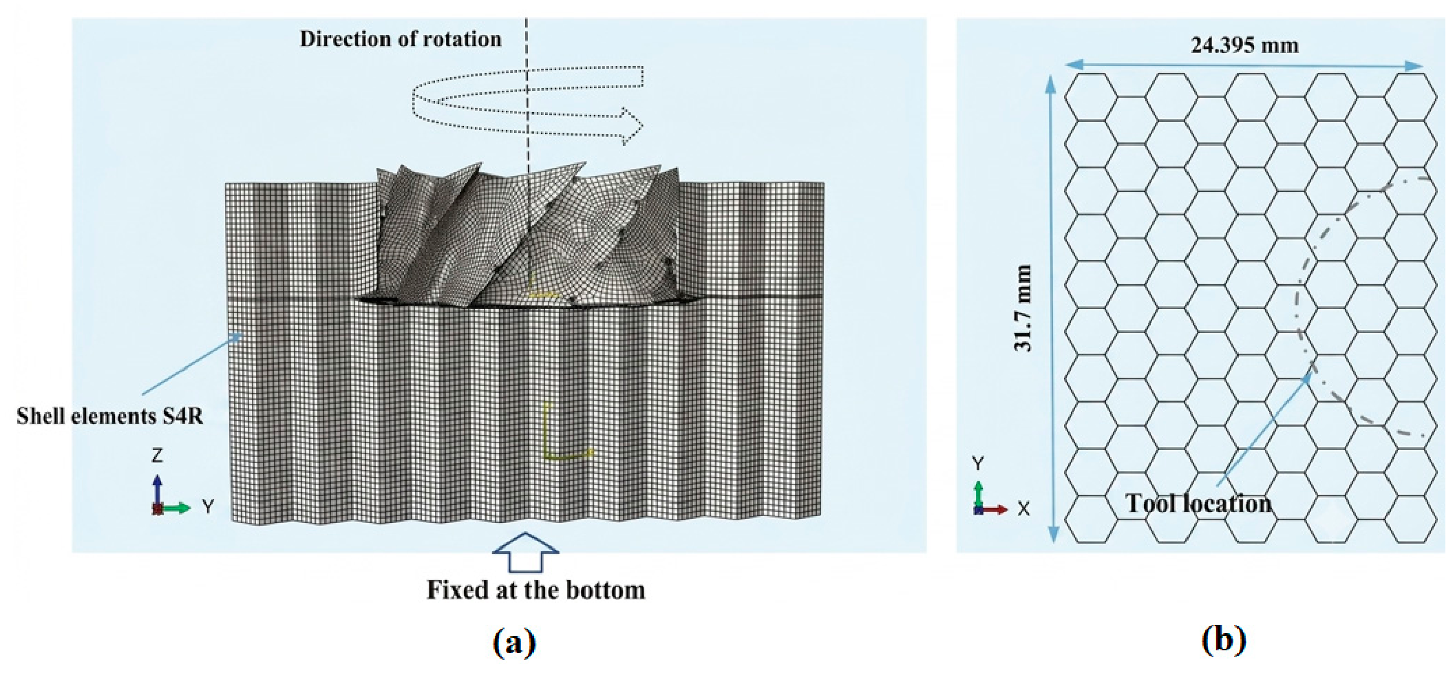
The objective of this study is to develop a numerical model of the milling process for aluminum honeycomb structures, which are widely used in the aerospace industry because of their excellent mechanical performance and low density. The proposed methodology consists of first developing and validating a numerical model for conventional milling. This model is then extended to incorporate a hybrid formulation that accounts for the combined effects of longitudinal and torsional ultrasonic vibrations, thereby accurately reproducing the actual operating conditions of the vibration-assisted machining process. Three-dimensional numerical simulations were performed using Abaqus/Explicit (Version 6.17). This modeling approach enables accurate representation of the complex mechanical interactions between the cutting tool and the thin honeycomb cell walls during machining. The finite element model consists of hexagonal cells with single- and double-wall configurations, having wall thicknesses of 0.017 mm and 0.034 mm, respectively, consistent with the geometric characteristics of the experimental honeycomb structure (Figure 2). The thin cell walls were discretized using four-node reduced-integration quadrilateral shell elements (S4R). This element formulation provides an optimal balance between geometric accuracy and computational efficiency (Figure 4b). The cutting tool was modeled as a rigid body, since the stresses acting on the tool are negligible compared with the large deformations experienced by the thin honeycomb cell walls. The tool was discretized using four-node rigid quadrilateral elements (R3D4) (Figure 5b). The reliability of finite element simulations depends strongly on satisfying convergence and numerical stability requirements. Among the governing numerical parameters, the mesh density plays a crucial role because it directly affects both the geometric representation of the model and its ability to accurately capture localized mechanical phenomena. Although mesh refinement generally improves the resolution of the stress field, particularly in regions with high stress gradients or complex contact conditions, it also leads to a significant increase in computational cost and simulation time. Conversely, a coarser mesh reduces computational requirements but may compromise the accuracy and overall reliability of the numerical predictions. To ensure that the numerical results were independent of the mesh density, a mesh convergence study was conducted using several element sizes. The cutting force components were selected as the convergence criterion because they constitute the primary quantities of interest in this study. The results showed that reducing the element size below 0.3 mm produced only negligible variations in the predicted cutting forces, while significantly increasing the computational time. Therefore, the mesh was defined by achieving an appropriate balance between numerical accuracy and computational efficiency, thereby ensuring reliable predictions within a reasonable computational time. A uniform element size of 0.3 mm was adopted throughout the honeycomb structure. This mesh resolution provides an accurate representation of the geometric features while maintaining an acceptable computational cost. The resulting finite element model (FEM) comprises 25,628 elements, providing a satisfactory compromise among solution accuracy, numerical stability, and computational efficiency.
The numerical model incorporates two main categories of contact interactions between the cutting tool and the honeycomb structure. The first corresponds to the primary contact between the cutting tool and the honeycomb cell walls during the milling process. The second includes secondary contacts occurring after tool passage, including interactions between adjacent cell walls and contacts between the generated chips and the unmachined material. Explicit modeling of these contact interfaces enables accurate reproduction of the local process kinematics while ensuring the numerical stability and robustness of the simulation. At the tool–workpiece interface, a constant coefficient of friction was adopted. Rather than representing an intrinsic tribological property of the contacting materials, this value was considered an equivalent phenomenological coefficient that characterizes the overall macroscopic contact behavior under ultrasonic vibration assistance. To address the limitations associated with this assumption, it should be emphasized that the selected coefficient was adopted from the existing literature on the numerical modeling of ultrasonic vibration-assisted machining. Although the use of a constant friction coefficient represents a simplification of the local and cyclic tribological phenomena occurring at the interface, this assumption is justified by the fact that the primary effect of ultrasonic vibrations is to reduce the time-averaged real contact area between the tool and the workpiece. Consequently, the use of an effective constant coefficient enables robust prediction of the overall reduction in cutting forces at the macroscopic scale while avoiding unnecessary numerical complexity. This simplified yet validated approach is consistent with established practices in the macroscopic modeling of ultrasonic vibration-assisted machining processes [23]. In this context, the adopted approach provides a stable representation of the reduction in interfacial shear stresses while capturing the localized and intermittent contact interactions between the cutting edges and the thin honeycomb cell walls, without introducing excessive numerical complexity into the three-dimensional model. Furthermore, to ensure realistic contact interactions between the toothed cutting tool and the honeycomb structure, a preliminary contact initialization step was implemented. This procedure accounts for both the geometry of the milling cutter and the cellular architecture of the honeycomb core, as illustrated in Figure 4b. The boundary conditions applied to the tool–workpiece system accurately reproduce the experimental clamping configuration. The specimen was laterally constrained between two fixtures, which was numerically represented by symmetry boundary conditions applied to the honeycomb boundaries with respect to the X-plane (Ux = URy = URz = 0) and the Y-plane (Uy = URx = URz = 0), thereby preventing rigid-body motion in the constrained directions.
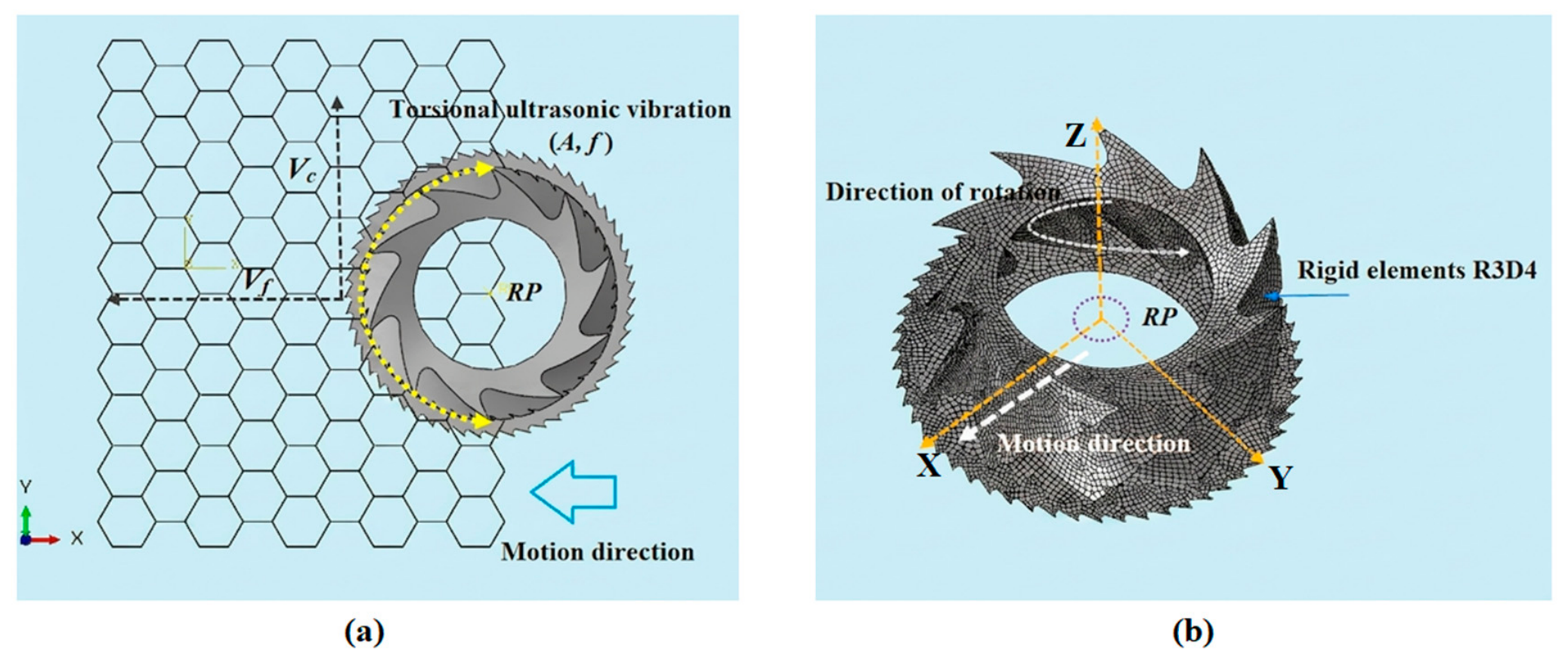
Ultrasonic vibration-assisted milling (UVAM), also referred to as rotary ultrasonic machining (RUM), represents a significant advancement in high-precision machining technologies. This process is based on the superposition of multiple kinematic motions, thereby enhancing the overall machining performance. Its fundamental principle consists of superimposing high-frequency ultrasonic vibrations onto the cutting tool, which are typically transmitted to the active cutting zone. This periodic excitation modifies the tool–workpiece contact conditions relative to conventional machining, leading to improved tribological behavior and more favorable cutting conditions. As a result, cutting forces are reduced, surface quality is enhanced, and the overall machining performance is improved. Compared with conventional milling, ultrasonic vibration-assisted milling can be classified into two main configurations: longitudinal ultrasonic vibration-assisted milling (L-UVAM) and longitudinal–torsional ultrasonic vibration-assisted milling (LT-UVAM). In the first configuration, ultrasonic vibrations are applied exclusively along the axial (Z) direction of the cutting tool. In contrast, the second configuration combines axial and torsional ultrasonic vibrations about the same axis, thereby generating a coupled longitudinal–torsional motion (Figure 5a). This machining process is based on the synchronized superposition of three fundamental motions: tool rotation about the Z-axis at a spindle speed n, linear translation along the X-axis corresponding to the feed rate Vf, and longitudinal ultrasonic vibration applied along the Z-axis. The interaction of these motions produces a modified cutting regime characterized by reduced friction, improved chip evacuation, and enhanced material removal efficiency. Consequently, the incorporation of longitudinal ultrasonic vibrations significantly improves the overall performance of the machining process. These high-frequency longitudinal vibrations, applied along the Z-axis, reduce the contact time between the cutting tool and the workpiece, thereby decreasing friction and facilitating material removal, which ultimately enhances cutting efficiency. Simultaneously, a torsional ultrasonic vibration is superimposed about the Z-axis onto the conventional rotational motion of the tool (Figure 5a). The combined action of the longitudinal and torsional vibrations generates a helical tool motion, producing a spiral tool trajectory within the workpiece. Within the Abaqus finite element framework, the complex motion of the cutting tool is defined through a reference point (RP) located on its axis of rotation, enabling all translational and rotational degrees of freedom to be coupled and controlled (Figure 5b). The tool kinematics are explicitly prescribed as follows: rotation about the Z-axis, imposed through an angular velocity corresponding to the spindle speed n, governs material removal; linear translation along the X-axis, corresponding to the feed rate Vf, reproduces the tool feed motion; and longitudinal and torsional ultrasonic vibrations are applied along and about the Z-axis, respectively, with amplitudes A and an excitation frequency f (Figure 5a). In Abaqus, these kinematic components are coupled through a multi-degree-of-freedom (MDOF) reference point, enabling the consistent and realistic superposition of rotational, translational, and ultrasonic vibrational motions within the numerical model. This approach enables accurate prediction of the machining forces while ensuring time-resolved tracking of the tool–workpiece contact point in the global (x, y, z) coordinate system. The developed numerical model consistently reproduces the mechanical interactions between the cutting tool and the workpiece, as well as the effects induced by ultrasonic vibrations, thereby ensuring the numerical stability and reproducibility of the simulations. Under longitudinal–torsional ultrasonic vibration-assisted milling (LT-UVAM), the active cutting edge follows a highly nonlinear three-dimensional trajectory. This modified kinematic behavior improves tool engagement with the workpiece while reducing dynamic instabilities and surface defects. It therefore constitutes the fundamental basis of the kinematic analysis developed in this study. To ensure a consistent description of the machining system, an orthonormal coordinate system was defined, in which the Y-axis corresponds to the feed direction, the X-axis represents the radial depth-of-cut direction, and the Z-axis denotes the axial cutting direction. For conventional milling, the motion of the cutting edge can be described by the mathematical formulation reported in the literature [24], which serves as the reference model for its extension to the three-dimensional kinematic formulation incorporating the effects of ultrasonic vibrations.
x t = V f t + r   c o s ( 2 π n t 60 ) y t = r   s i n ( 2 π n t 60 ) z t = 0
The parameter Vf represents the tool feed rate and is expressed in millimeters per minute (mm/min). The spindle rotational speed, denoted by n, is expressed in revolutions per minute (rpm), whereas r corresponds to the cutting tool radius, expressed in millimeters (mm).
Longitudinal–torsional ultrasonic vibration-assisted milling (LT-UVAM) differs from conventional milling by the simultaneous superposition of two coupled vibration modes. In this configuration, the key innovation lies in the use of an ultrasonic horn with a helical-groove geometry, excited under a specific vibration mode. The horn is designed such that its excitation frequencies coincide with the natural frequencies of the vibrating system, thereby enabling efficient coupling between the longitudinal and torsional vibration modes. This frequency matching enhances the dynamic stability of the tool–horn assembly while maximizing the transmission of ultrasonic vibrational energy to the cutting zone. Under these conditions, the longitudinal displacement of the tool tip can be expressed as follows:
z t =   A sin 2 π f t
In the above expression, f denotes the ultrasonic vibration frequency, expressed in hertz (Hz), whereas A represents the amplitude of the longitudinal oscillatory displacement, expressed in millimeters (mm). This parameter characterizes the intensity of the ultrasonic excitation applied to the system.
The longitudinal–torsional ultrasonic vibration-assisted milling (LT-UVAM) process can be regarded as an extension of conventional milling, in which longitudinal and torsional ultrasonic vibration modes are superimposed onto the tool motion. In this configuration, the disc-type cutting tool is simultaneously subjected to high-frequency axial oscillations and torsional vibrations synchronized with its rotational motion. The superposition of these vibration modes fundamentally modifies the cutting kinematics, resulting in a more complex three-dimensional trajectory of the cutting tool during machining. Accordingly, the tool motion can be mathematically described by the following expression [25]:
x 1 t =   V f t + r cos ( 2 π n t 60 + A   sin ( 2 π f t ) ) y 1 t = r sin ( 2 π n t 60 + A   sin ( 2 π f t ) ) z 1 t =   A   sin ( 2 π f t + φ 0 )
In this model, A denotes the common amplitude of the longitudinal and torsional ultrasonic vibrations. Since both vibration components originate from the same excitation source, they share a common ultrasonic frequency, denoted by f. The parameter φ0 represents the phase shift between the longitudinal and torsional vibration modes and is expressed in radians. Moreover, Vc and Vf denote the cutting speed and feed rate, respectively, whereas nnn represents the spindle rotational speed. The variable t corresponds to the time evolution of the system. In all simulations, the ultrasonic frequency was fixed at 21.06 kHz, while the vibration amplitude was set to 25 µm.

3. Material Properties, Degradation Mechanisms and Failure Factors

The Johnson–Cook constitutive model is a thermo-viscoplastic phenomenological model developed to account for the combined effects of strain, strain rate, and temperature on the mechanical behavior of materials. Owing to its robustness and computational efficiency, it has been widely implemented in commercial finite element codes and has become a reference constitutive model for machining simulations [26,27]. The model is expressed in a multiplicative form (Equation (2)), in which the material response is decomposed into three independent contributions representing strain hardening, strain-rate sensitivity, and thermal softening, respectively [28]. Its analytical expression is given as follows:
σ ¯ = A + B ε ¯ n [ 1 + C l n ( ε ¯ ˙ ε ¯ ˙ 0 ) ]   [ 1     ( T T 0 T f T 0 ) n ]
In this thermo-viscoplastic constitutive model, the material behavior is governed by the characteristic parameters A, B, C, n, and m. The variables Tm, T0, and ε ¯ ˙ 0 denote the melting temperature, the reference temperature, and the reference strain rate, respectively.
The thermomechanical properties, together with the Johnson–Cook constitutive and damage parameters of the 5056-aluminum alloy honeycomb core, were adopted from the literature [29,30,31], as summarized in Table 1 and Table 2. These experimentally validated parameters have been widely used in machining simulations, thereby ensuring the reliability and credibility of the present numerical model.
During the milling of aluminum honeycomb structures, material removal is accompanied by chip formation and ejection, phenomena that are intrinsically governed by plastic deformation and material failure mechanisms. Accurate numerical simulation of this process requires the implementation of a damage criterion capable of reproducing the progressive evolution of material degradation leading to fracture. Among the available models, the Johnson–Cook damage criterion, expressed in Equation (5), is one of the most widely used for machining simulations because it accounts for the combined effects of plastic strain, strain rate, and temperature on damage initiation [28]. According to this formulation, damage accumulates progressively during deformation until the damage variable reaches the critical value of 1, at which point material failure is initiated, resulting in material separation and subsequent chip formation.
ε f = [ d 1 + d 2 ε [ d 3 σ m σ ¯ ] ]   [ 1 + d 4 l n ( ε ¯ ˙ ε ¯ ˙ 0 ) ]   [ 1 d 5 ( T   T 0 T f   T 0 ) ]
where ε f is the equivalent plastic strain at fracture. The state variables and parameters are defined as follows: σ is the mean hydrostatic stress, and σ ¯ is the von Mises equivalent stress, where the ratio σm/ σ represents the stress triaxiality. Additionally, ε ˙ ¯ represents the equivalent plastic strain rate, while ε 0 ˙ ¯ is the reference strain rate. The temperature terms T, T0, and Tf correspond to the current material temperature, the reference (room) temperature, and the melting temperature of the material, respectively. The coefficients d1, d2, d3, d4, and d5 constitute the fundamental parameters of the Johnson–Cook damage model and represent the material’s response to fracture mechanisms under complex mechanical stresses. Specifically, d1, d2, and d3, govern the influence of stress triaxiality on the failure strain, d4 accounts for the strain rate sensitivity, and d5 models the thermal softening effect. These phenomenological constants govern the evolution of the strain at failure as a function of the stress state and applied loading conditions. The values adopted in this study are derived from experimentally validated literature data widely used in machining process modeling. They are summarized in Table 2 [32].
The accurate prediction of cutting forces is a key challenge in machining process analysis, as these forces directly influence surface quality, dimensional accuracy, and the overall performance of the machining system. They reflect the underlying mechanisms of material deformation and failure within the cutting zone and provide valuable insight into tool–workpiece interactions. Therefore, a thorough understanding of cutting forces is essential for optimizing machining parameters, minimizing vibrations, reducing tool wear, and ensuring process stability. In the present study, the cutting forces were evaluated using the formulation proposed in Ref. [33], which has been shown to reliably predict the cutting loads generated during the milling of aluminum honeycomb structures.
F x = 1 t 2 t 1 t 1 t 2 F C X   d t
F y = 1 t 2 t 1 t 1 t 2 F C Y   d t
F z = 1 t 2 t 1 t 1 t 2 F C Z   d t

4. Results and Discussion

4.1. Comparison of Model and Experiment and the Contribution of Vibration Assistance to Machining Forces

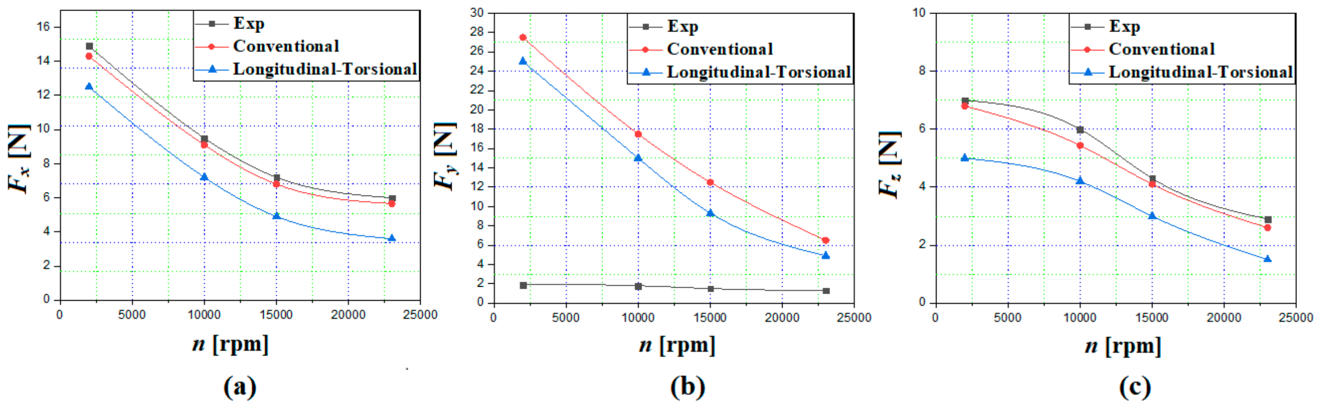
The validation of a numerical model in machining relies on its ability to accurately reproduce physical phenomena, particularly the evolution of cutting forces as a function of the process parameters. Figure 6 illustrates a comparative analysis of the three cutting force components over a spindle speed range from 2000 to 23,000 rpm, comparing the experimental data with the predictions of both the conventional milling model and the advanced longitudinal–torsional (LT-UVAM) vibration-assisted milling model. A comparison between the experimental results and the conventional model demonstrates excellent quantitative agreement for the (Fx) and (Fz) components. At a low spindle speed of 2000 rpm, the conventional model exhibits minimal discrepancies of approximately 4% for (Fx) (14.3 N predicted versus 14.9 N measured) and 3% for (Fz) (6.8 N predicted versus 7.0 N measured). At the maximum spindle speed of 23,000 rpm, the accuracy remains high, with deviations below 5% for (Fx) and 7% for (Fz). This strong correlation validates the material constitutive law and the thermal softening formulation implemented in the numerical model. However, a significant discrepancy is observed for the (Fy) component. While the experimental force remains nearly constant at approximately 2 N over the entire spindle speed range, the conventional model considerably overestimates this component, predicting values ranging from 27.5 N at low spindle speeds to 6.5 N at the highest spindle speed. Since this discrepancy exceeds one order of magnitude at low spindle speeds, it cannot be explained solely by experimental measurement uncertainty, which is inherently greater for low-magnitude forces approaching the lower calibration limit of the force sensor. Instead, this discrepancy indicates a structural limitation of the numerical formulation along the Y-axis. The model likely suffers from inadequate calibration of the directional friction coefficients or an incomplete representation of the tool–workpiece contact kinematics along this specific shear plane. These aspects require dedicated tribological characterization in future work. A comparison between the conventional model and the longitudinal–torsional ultrasonic vibration-assisted milling (LT-UVAM) model reveals a systematic attenuation of the cutting forces over the entire spindle speed range. For the (Fx) component, the introduction of longitudinal–torsional vibrations results in a predicted force reduction ranging from 12% at 2000 rpm to 36% at 23,000 rpm compared with the conventional milling model. Similarly, for the (Fz) component, the predicted force reduction ranges from 26% to more than 42%. This force attenuation is directly supported by the kinematic analysis. The high-frequency superposition of longitudinal and torsional oscillations introduces an intermittent micro-cutting regime. The periodic separation between the cutting edge and the workpiece significantly reduces the effective tool–workpiece contact time and lowers the average tool–chip friction, thereby directly accounting for the simulated reduction in macroscopic cutting forces. Consequently, the industrial applications of these two models are complementary. The conventional model provides a reliable basis for structural design and spindle power estimation based on the primary cutting force components (Fx) and (Fz). Meanwhile, the LT-UVAM model provides a predictive tool for quantifying potential energy savings and optimizing machining parameters, thereby offering valuable guidance for reducing tool wear and preventing chatter in high-value-added machining applications.

4.2. Influence of Cutting Forces and Vibration Assistance on the Stability and Integrity of Thin Walls in Honeycomb Structures

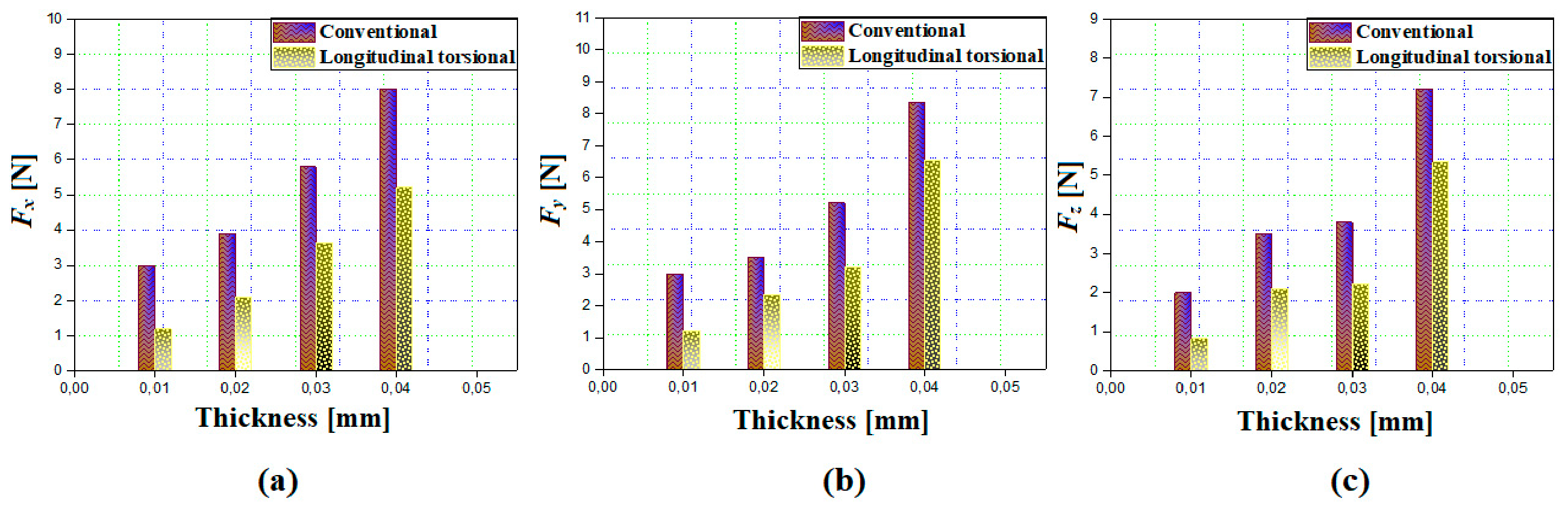
The investigation of cutting geometric parameters is a fundamental step in assessing the performance, stability, and feasibility of machining processes, particularly when machining thin-walled honeycomb structures. Figure 7 illustrates the evolution of the three cutting force components as a function of wall thickness, varying from 0.01 to 0.04 mm. The results compare the conventional milling model with the longitudinal–torsional ultrasonic vibration-assisted milling (LT-UVAM) model to quantitatively evaluate their respective performances and provide a mechanical interpretation of the influence of wall thickness on the machining response of aluminum honeycomb structures. The conventional milling model exhibits a nearly linear increase in all cutting force components with increasing wall thickness. The (Fx) component increases from 3.0 N at a wall thickness of 0.01 mm to 8.0 N at 0.04 mm, corresponding to an increase of approximately 62.5%. Similarly, (Fy) increases from 3.0 N to 8.35 N (64%), while the axial force (Fz) rises from 2.0 N to 7.2 N, representing an increase of more than 72.2%. This trend is primarily attributed to the increase in the instantaneous undeformed chip cross-sectional area. As the wall thickness increases, a larger volume of material must undergo plastic deformation ahead of the cutting edge, thereby increasing the shear resistance encountered during cutting and, consequently, the required cutting forces. Because the walls of aluminum honeycomb structures are extremely thin (typically less than 0.1 mm), they possess a very small second moment of area and consequently exhibit low bending stiffness. The transverse force components, (Fx) and (Fy), act perpendicular to these thin cell walls, generating localized bending moments. When these forces exceed the critical buckling load, the cell walls become susceptible to elastic instability, leading to local buckling, tearing, or permanent deformation, which ultimately compromises the geometric integrity and dimensional accuracy of the honeycomb cells. A comparison with the LT-UVAM model reveals a systematic and significant reduction in cutting forces throughout the investigated wall thickness range. For the minimum wall thickness of 0.01 mm, ultrasonic vibration assistance reduces all three force components ((Fx), (Fy), and (Fz)) by approximately 60%. Even at the maximum wall thickness of 0.04 mm, substantial reductions are maintained, reaching approximately 35% for (Fx), 22% for (Fy), and 26% for (Fz). The reduction in cutting forces can be explained by the modified cutting kinematics introduced by the combined longitudinal and torsional ultrasonic vibrations. The superposition of these high-frequency oscillations generates an intermittent cutting regime in which the cutting edge periodically separates from the workpiece. This intermittent contact substantially reduces the effective tool–workpiece contact time and decreases the average friction at the tool–chip interface. Consequently, resistance within the primary shear zone is reduced, while heat dissipation is enhanced, contributing to lower cutting forces throughout the machining process. From an industrial perspective, these results demonstrate the potential of longitudinal–torsional ultrasonic vibration assistance for machining aluminum honeycomb structures. Although the present numerical model is limited to the prediction of cutting forces and does not directly evaluate the internal stress distribution or the deformation of the cell walls, the significant reduction in cutting forces—reaching up to 60%—constitutes a strong indicator of improved machining conditions. By substantially decreasing the transverse and axial mechanical loads applied to the thin-walled structure, the LT-UVAM process reduces the mechanical energy transmitted to the honeycomb core, thereby lowering the risk of local buckling, wall deflection, and structural damage. Consequently, longitudinal–torsional ultrasonic vibration assistance represents a promising approach for increasing machining productivity by enabling higher material removal rates while preserving the structural integrity of thin-walled honeycomb components and mitigating the risk of chatter.

4.3. Mechanisms of Adhesive Wear Evolution Under the Effect of Combined Ultrasonic Vibrations

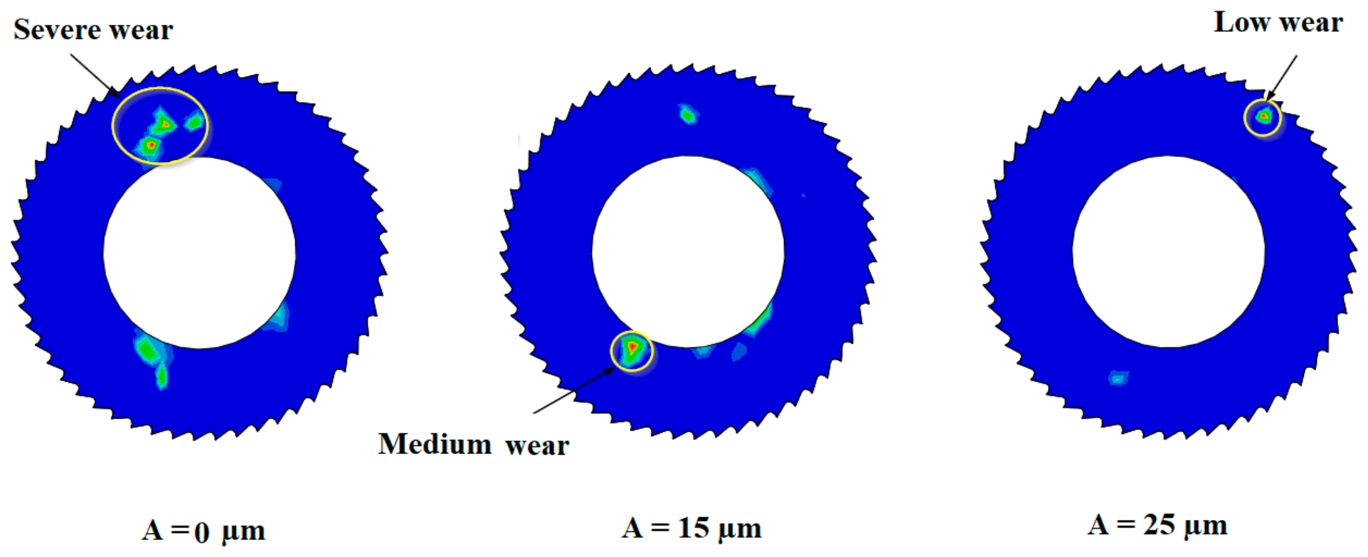
Adhesive wear is one of the predominant mechanisms of tool degradation during the milling of aluminum honeycomb structures. Owing to the high ductility, low shear strength, and strong tribological affinity of aluminum with cutting tool materials, material transfer to the cutting edge is particularly pronounced. Figure 8 illustrates the morphology of the adhesion zones observed on the CZD10 tool under different longitudinal–torsional ultrasonic vibration amplitudes. A progressive reduction in the extent of adhesion is observed as the vibration amplitude increases, indicating a significant improvement in resistance to adhesive wear under ultrasonic vibration assistance. Under conventional milling conditions (A = 0) µm), the tool–workpiece interface is characterized by nearly continuous contact. High contact pressures, combined with frictional heating, promote the formation of metallic micro-junctions between the asperities of the tool and the workpiece. These micro-junctions progressively develop during sustained contact, resulting in significant material transfer to the cutting edge. Their repeated rupture under shear loading causes aluminum fragments to detach from the workpiece, some of which remain adhered to the tool surface. The successive accumulation of these fragments eventually leads to the formation of an unstable built-up edge and extensive adhesion zones, as shown in Figure 8. This phenomenon increases friction, elevates the local temperature, and raises the cutting forces, thereby accelerating tool degradation. When the vibration amplitude is increased to 15 µm, a marked reduction in the adhesion zones is observed. This improvement results from the substantial modification of the contact conditions induced by longitudinal–torsional ultrasonic vibrations. The ultrasonic oscillations generate successive cycles of contact and separation between the cutting edge and the workpiece, thereby reducing the effective contact time. Consequently, the formation and growth of adhesive micro-junctions are significantly restricted, while their premature rupture prevents them from reaching a critical size capable of promoting severe material transfer. As a result, the amount of aluminum adhering to the cutting edge is considerably reduced, leading to a lower adhesive wear rate. A further increase in the vibration amplitude to 25 µm enhances this beneficial effect. The larger oscillation amplitude promotes a highly intermittent cutting regime, substantially reducing both the effective contact area and the contact time between the tool and the workpiece. Consequently, the cutting forces, frictional stresses, and friction-induced heat generation are simultaneously reduced. In addition, aluminum particles adhering to the tool are subjected to high cyclic accelerations generated by the combined longitudinal and torsional vibrations. These dynamic loading conditions facilitate their rapid detachment before they can stabilize on the cutting edge. Consequently, only slight traces of adhered material remain on the tool surface, indicating a significant reduction in adhesive wear. The numerical interpretation of this mechanism is based on the tribological interactions occurring at the tool–workpiece interface. The severity of adhesive wear is governed by four principal parameters: the effective contact time, the normal contact pressure, the interfacial temperature, and the relative sliding distance. These parameters directly control the probability of adhesive micro-junction formation, as well as their growth and rupture during machining. The application of longitudinal–torsional ultrasonic vibrations simultaneously modifies all four parameters by reducing the effective contact time, lowering the average contact pressure, limiting frictional heat generation, and continuously disrupting the nucleation and growth of adhesive junctions. From a physical standpoint, the improvement observed with increasing vibration amplitude results from the combined action of several complementary mechanisms. First, the reduction in effective contact time limits the formation of metallic micro-welds. Second, the decrease in the actual contact area reduces the number of potential nucleation sites for adhesive junctions. Third, the reduction in the cutting-zone temperature limits atomic diffusion and weakens the metallurgical affinity between aluminum and the cutting tool material. Finally, the torsional vibration component generates oscillatory tangential stresses that promote the removal of adhered particles before they accumulate into a stable built-up edge. Overall, the progressive reduction in the adhesion zones observed experimentally demonstrates that increasing the ultrasonic vibration amplitude significantly improves the tribological conditions at the tool–workpiece interface. The intermittent cutting mechanism effectively limits material transfer, suppresses built-up edge formation, and enhances the wear resistance of the CZD10 tool during the milling of aluminum honeycomb structures. These findings confirm that vibration amplitude is a key process parameter for controlling adhesive wear and extending tool life in longitudinal–torsional ultrasonic vibration-assisted milling.

4.4. Analysis of the Influence of Vibration Frequency on the Deformation of the Walls of a Cellular Structure

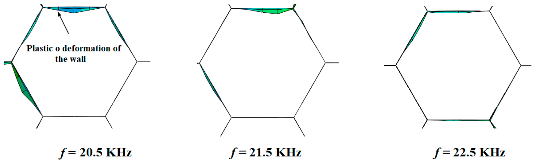
The influence of ultrasonic excitation frequency on the deformation response of aluminum honeycomb structures is governed by complex dynamic interactions involving structural vibrations and stress redistribution within the periodic cellular architecture. Over the investigated frequency range of 20.5–22.5 kHz, the numerical results reveal a progressive yet non-linear evolution of the deformation field, affecting both the magnitude and spatial distribution of the highly stressed regions, as illustrated in Figure 9. At an excitation frequency of 20.5 kHz, pronounced localized deformation is observed, with the highest strain concentrations occurring primarily at the cell-wall junctions and along the edges of the hexagonal cells. This response suggests that the excitation frequency approaches a highly responsive dynamic condition of the structure, resulting in amplified wall displacements and elevated stress concentrations. Under these conditions, a significant fraction of the ultrasonic energy is converted into deformation energy, promoting the onset of localized plastic deformation in regions where the equivalent stress exceeds the material yield strength. Increasing the excitation frequency to 21.5 kHz produces a noticeable redistribution of the deformation field. The strain distribution becomes more heterogeneous, with some regions exhibiting reduced strain levels while others experience increased stress concentrations. This behavior reflects a modification of the structural dynamic response associated with changes in the vibration pattern. Owing to the periodic geometry of the honeycomb core, elastic-wave propagation is strongly influenced by multiple scattering, wave interference, and modal interactions. Consequently, the vibrational energy is redistributed through alternative load-transfer paths within the cellular network, leading to a partial reduction in the maximum deformation while maintaining localized plastic zones. At 22.5 kHz, the overall structural response becomes less pronounced and more spatially confined. The magnitude of plastic deformation decreases significantly and remains restricted to a limited number of localized regions. This trend indicates that the excitation frequency moves away from the dynamic conditions associated with the highest structural response, thereby reducing the efficiency of energy transfer from the ultrasonic source to the honeycomb walls. Consequently, both the displacement amplitudes and the associated stress concentrations decrease substantially. From a physical perspective, these observations result from the interaction between the ultrasonic excitation and the periodic topology of the honeycomb structure. The cellular architecture modifies elastic-wave propagation through transmission, reflection, and interference phenomena, thereby controlling the spatial distribution of vibrational energy within the structure. As a result, deformation localization strongly depends on the excitation frequency. At lower frequencies, where the dynamic response is more pronounced, vibrational energy tends to concentrate in localized regions, promoting plastic deformation. As the excitation frequency increases within the investigated range, energy transfer to the structure becomes progressively less efficient, leading to lower deformation levels and reduced stress concentrations. Overall, the coupled effects of excitation frequency, structural dynamics, and wave propagation provide a plausible explanation for the gradual reduction in deformation severity observed between 20.5 and 22.5 kHz.

4.5. Chip Formation and Fragmentation Mechanisms in Conventional and Vibration-Assisted Machining

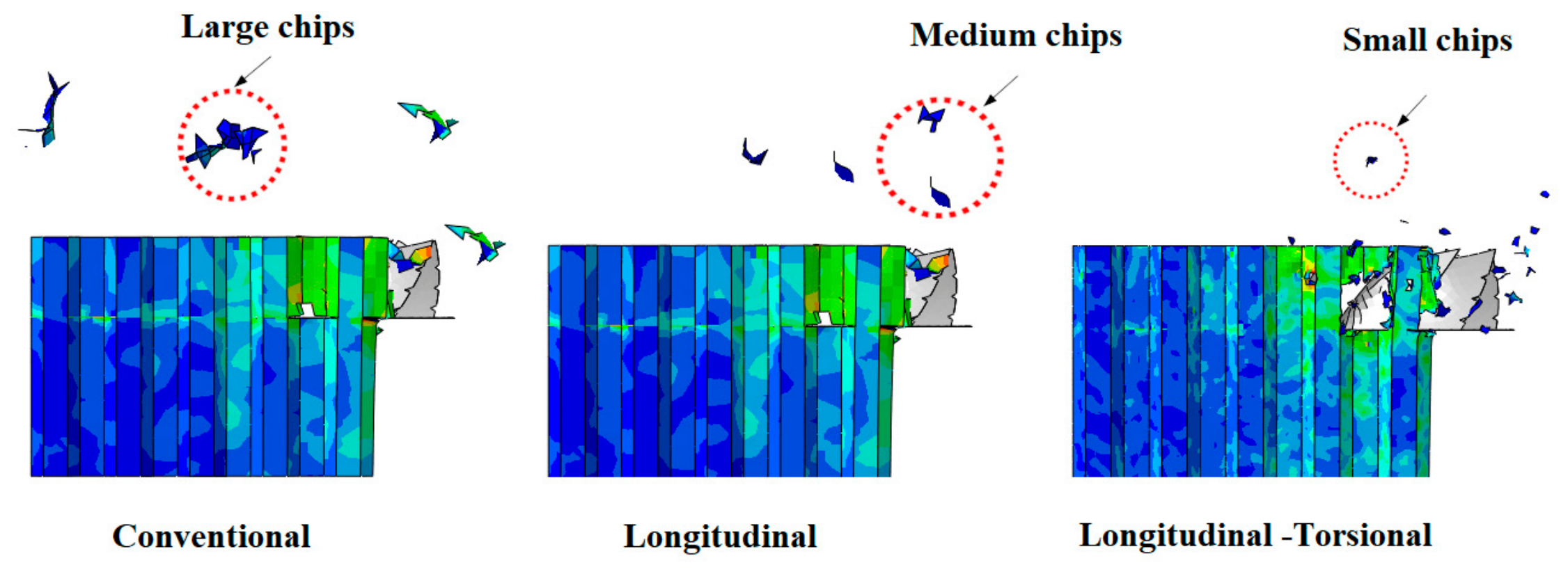
Figure 10 presents the finite element simulation results, highlighting the significant effect of different machining strategies on chip morphology and fragmentation during the milling of aluminum honeycomb structures. A comparison between conventional machining (CM), longitudinal vibration-assisted machining (LVAM), and longitudinal–torsional ultrasonic vibration-assisted milling (LT-UVAM) reveals a progressive and pronounced reduction in chip size as the complexity of the tool vibration increases. This evolution reflects substantial changes in the mechanisms of plastic deformation, damage evolution, and material fracture within the cutting zone. Under conventional machining conditions, chip formation results from continuous contact between the cutting tool and the workpiece. This continuous interaction establishes a stable cutting regime characterized by the development of a well-defined primary shear zone, in which the equivalent von Mises stress is distributed relatively uniformly. As the cutting-edge advances, the material undergoes extensive plastic deformation before being removed in the form of a continuous or slightly segmented chip. As shown in Figure 10, this mechanism produces relatively large chips, reflecting the continuous plastic flow of the material along the rake face. This cutting regime is also associated with a large tool–chip contact area, which promotes high frictional forces and significant heat generation within the cutting zone. The introduction of longitudinal ultrasonic vibrations substantially modifies the cutting mechanism. The axial oscillatory motion of the cutting tool periodically changes the instantaneous uncut chip thickness, producing successive phases of tool engagement and disengagement. This intermittent cutting regime disrupts the continuous plastic flow observed under conventional machining conditions. The repeated loading and unloading cycles promote localized stress and strain concentrations, facilitating the formation of adiabatic shear bands and the initiation of localized cracking. Consequently, chip segmentation becomes more pronounced, leading to a significant reduction in the average chip size compared with conventional machining. As illustrated in Figure 10, this enhanced fragmentation is accompanied by a reduction in the effective tool–workpiece contact time, which limits adhesion phenomena and facilitates chip evacuation. The most significant changes are observed under LT-UVAM conditions, where longitudinal vibrations are superimposed with torsional oscillations. This combined excitation generates a complex three-dimensional trajectory of the cutting edge, profoundly modifying the stress state within the material ahead of the tool. The simultaneous action of axial and tangential vibrations produces a multiaxial stress state that promotes damage initiation and material fracture. As shown in Figure 10, the equivalent stress field extends over a larger region surrounding the cutting zone, while the stress distribution becomes more diffuse than under the CM and LVAM conditions. The combined action of compressive, longitudinal shear, and torsional shear stresses promotes the activation of multiple fracture planes and accelerates the initiation, propagation, and coalescence of microcracks. From a mechanical perspective, the material is no longer able to sustain the continuous plastic flow observed during conventional machining. Instead, the material removal process is governed predominantly by repeated micro-fracture and dynamic fragmentation mechanisms. Consequently, the resulting chips become considerably finer, appearing as small fragments and particles, as clearly illustrated in Figure 10. This enhanced fragmentation reduces the energy required for material separation and facilitates rapid chip evacuation from the cutting zone. From both tribological and thermal perspectives, the substantial reduction in chip size significantly decreases the effective tool–chip contact area, thereby reducing adhesion, material sticking, and friction at the interface. In addition, the smaller chips promote more efficient heat dissipation from the cutting zone, limiting heat accumulation near the cutting edge. Collectively, these mechanisms explain the superior performance of the LT-UVAM process in controlling chip fragmentation, reducing tribological loading, and potentially improving the surface integrity of machined aluminum honeycomb structures.

5. Conclusions

This study investigated the machining mechanisms of 5056 aluminum alloy honeycomb structures using longitudinal–torsional ultrasonic vibration-assisted milling (LT-UVAM) with a 55-tooth CZD10 cutter. A three-dimensional finite element model was developed in Abaqus/Explicit and validated against experimentally measured cutting force components. The satisfactory agreement between the numerical predictions and the experimental measurements confirms the reliability of the proposed model for accurately describing the cutting process. Following this validation, the finite element model was employed as a numerical tool to investigate the effects of machining conditions on cutting forces, wall deformation, tool wear, and chip formation, providing insights that are difficult to obtain through experiments alone. The main findings of this study are summarized as follows:
  • LT-UVAM significantly reduces cutting forces over the entire spindle speed range, with the axial force (Fz) decreasing by 26–42% due to the intermittent cutting mechanism and reduced tool–workpiece contact.
  • For ultra-thin honeycomb walls (0.01–0.04 mm), LT-UVAM decreases cutting forces by up to 60%, limiting wall deformation and preventing buckling, tearing, and plastic collapse.
  • Ultrasonic vibrations with an amplitude of 25 µm effectively suppress adhesive wear and built-up edge formation, thereby reducing friction and significantly extending tool life.
  • The cutting performance is highly sensitive to ultrasonic frequency. An optimal frequency of 22.5 kHz improves process stability and minimizes wall damage, whereas 20.5 kHz promotes undesirable structural resonance and deformation.
  • The validated 3D finite element model accurately predicts machining behavior and demonstrates that LT-UVAM is an efficient and reliable solution for improving the precision, productivity, and sustainability of machining lightweight aerospace honeycomb structures.

Author Contributions

T.Z. performed analysis, methodology, interpreted data and results, and was a major contributor to writing the manuscript. O.B. performed analysis, methodology, interpreted data and results, and was a major contributor to writing the manuscript. J.-E.S. contributed to the supervision, methodology, and investigation; performed analysis, interpreted data and results, and was a contributor to writing the manuscript. M.J. performed analysis, interpreted data and results, and was a major contributor to writing the manuscript, investigation. M.N. contributed to the supervision, methodology, and investigation; performed analysis, interpreted data and results, and was a contributor to writing the manuscript. W.D. interpreted results and major contributor to writing the manuscript. M.B. interpreted results and major contributor to writing the manuscript. All authors have read and agreed to the published version of the manuscript.

Funding

This research received no external funding.

Data Availability Statement

No new data were created or analyzed in this study. Data sharing is not applicable to this article.

Conflicts of Interest

The authors declare no conflicts of interest.

References

  1. Ahmad, S.; Zhang, J.; Feng, P.; Yu, D.; Wu, Z.; Ke, M. Processing technologies for Nomex honeycomb composites (NHCs): A critical review. Compos. Struct. 2020, 250, 112545. [Google Scholar] [CrossRef] [Scilit]
  2. Liu, Y.; Liu, W.; Gao, W. Out-of-plane shear property analysis of Nomex honeycomb sandwich structure. J. Reinf. Plast. Compos. 2021, 40, 165–175. [Google Scholar]
  3. Ndiaye, E.B.; Maréchal, P.; Duflo, H. Adhesion characterization and defect sizing of sandwich honeycomb composites. Ultrasonics 2015, 62, 103–111. [Google Scholar] [CrossRef] [Scilit] [PubMed]
  4. Ding, M.; Zhang, P.; Zhang, Z.-Y.; Yao, S. A novel assembly technology of aluminum alloy honeycomb structure. Int. J. Adv. Manuf. Technol. 2010, 46, 1253–1258. [Google Scholar]
  5. Qiu, K.; Ming, W.; Shen, L.; An, Q.; Chen, M. Study on the cutting force in machining of aluminum honeycomb core material. Compos. Struct. 2017, 164, 58–67. [Google Scholar] [CrossRef] [Scilit]
  6. Wang, Z.; Tian, H.; Lu, Z.; Zhou, W. High-speed axial impact of aluminum honeycomb–Experiments and simulations. Compos. Part B Eng. 2014, 56, 1–8. [Google Scholar] [CrossRef] [Scilit]
  7. Ashab, A.S.M.; Ruan, D.; Lu, G.; Xu, S.; Wen, C. Experimental investigation of the mechanical behavior of aluminum honeycombs under quasi-static and dynamic indentation. Mater. Des. 2015, 74, 138–149. [Google Scholar] [CrossRef] [Scilit]
  8. An, Q.; Dang, J.; Ming, W.; Qiu, K.; Chen, M. Experimental and numerical studies on defect characteristics during milling of aluminum honeycomb core. J. Manuf. Sci. Eng. 2019, 141, 031006. [Google Scholar] [CrossRef] [Scilit]
  9. Yip-Hoi, D.; Gill, D.; Gahan, J.; Travis, G.; Mackaay, L. Material stiffness and cutting parameters for honeycomb aluminum sandwich panel: A comparison with bulk material. Procedia Manuf. 2019, 34, 385–392. [Google Scholar] [CrossRef] [Scilit]
  10. Wang, Y.; Gan, Y.; Liu, H.; Han, L.; Wang, J.; Liu, K. Surface quality improvement in machining an aluminum honeycomb by ice fixation. Chin. J. Mech. Eng. 2020, 33, 20. [Google Scholar] [CrossRef] [Scilit]
  11. Zarrouk, T.; Nouari, M.; Salhi, J.E.; Makich, H.; Salhi, M.; Atlati, S.; Salhi, N. Optimization of the milling process for aluminum honeycomb structures. Int. J. Adv. Manuf. Technol. 2022, 119, 4733–4744. [Google Scholar] [CrossRef] [Scilit]
  12. Hirayama, A. Method for Cutting Honeycomb Core. U.S. Patent No. 6,740,268, 25 May 2004. [Google Scholar]
  13. Wang, F.; Liu, J.; Li, L.; Shu, Q. Green machining of aluminum honeycomb treated using ice fixation in cryogenic. Int. J. Adv. Manuf. Technol. 2017, 92, 943–952. [Google Scholar] [CrossRef] [Scilit]
  14. Wang, F.; Wang, Y. Investigate on milling force of cryogenic cooling processing aluminum honeycomb treated by ice fixation. Int. J. Adv. Manuf. Technol. 2018, 98, 1253–1265. [Google Scholar] [CrossRef] [Scilit]
  15. Wang, F.; Wang, Y. Optimization of cryogenic milling parameters for aluminum honeycomb treated by ice fixation method. Int. J. Adv. Manuf. Technol. 2018, 99, 2271–2281. [Google Scholar] [CrossRef] [Scilit]
  16. Zarrouk, T.; Salhi, J.E.; Nouari, M.; Salhi, M.; Kodad, J. Influence of the cutting tool geometry on milling aluminum honeycomb structures. Int. J. Adv. Manuf. Technol. 2023, 126, 313–324. [Google Scholar] [CrossRef] [Scilit]
  17. Sun, J.; Dong, Z.; Wang, X.; Wang, Y.; Qin, Y.; Kang, R. Simulation and experimental study of ultrasonic cutting for aluminum honeycomb by disc cutter. Ultrasonics 2020, 103, 106102. [Google Scholar] [CrossRef] [Scilit] [PubMed]
  18. Kuo, C.; Chen, C.; Jiang, S.; Chen, Y. Effects of the tool geometry, cutting and ultrasonic vibration parameters on the cutting forces, tool wear, machined surface integrity and subsurface damages in routing of glass-fibre-reinforced honeycomb cores. J. Manuf. Process. 2023, 104, 59–75. [Google Scholar] [CrossRef] [Scilit]
  19. Liang, Y.; Feng, F.; Cao, W.; Song, G.; Yuan, X.; Xu, J.; Yue, Q.; Pan, S.; Jiang, E.; Ma, Y.; et al. Multi-Scale Study on Ultrasonic Cutting of Nomex Honeycomb Composites of Disc Cutters. Materials 2025, 18, 3476. [Google Scholar] [CrossRef] [Scilit] [PubMed]
  20. Liang, Y.; Feng, P.; Song, Z.; Zhu, S.; Wang, T.; Xu, J.; Yue, Q.; Jiang, E.; Ma, Y.; Song, G.; et al. Wear mechanisms of straight blade tool by dual-periodic impact platform. Int. J. Mech. Sci. 2025, 288, 110031. [Google Scholar] [CrossRef] [Scilit]
  21. Zarrouk, T.; Nouari, M.; Salhi, J.E.; Benbouaza, A. Numerical simulation of rotary ultrasonic machining of the Nomex honeycomb composite structure. Machines 2024, 12, 137. [Google Scholar] [CrossRef] [Scilit]
  22. Jaafar, M. Étude Expérimentale et Simulation Numérique de L’usinage des Matériaux en Nids D’abeilles: Application au Fraisage des Structures Nomex® et Aluminium. Ph.D. Thesis, Université de Lorraine, Nancy, France, 2018. [Google Scholar]
  23. Yang, Z.; Zhu, L.; Zhang, G.; Ni, C.; Lin, B. Review of ultrasonic vibration-assisted machining in advanced materials. Int. J. Mach. Tools Manuf. 2020, 156, 103594. [Google Scholar] [CrossRef] [Scilit]
  24. Zhang, M.; Hong, Y.; Li, X.; Zhang, Y.; Wang, X. Investigating the Surface Quality of Aramid Honeycomb Materials Through Longitudinal–Torsional Ultrasonic Milling. Machines 2024, 12, 768. [Google Scholar] [CrossRef] [Scilit]
  25. Xiang, D.; Wu, B.; Yao, Y.; Liu, Z.; Feng, H. Ultrasonic longitudinal-torsional vibration-assisted cutting of Nomex® honeycomb-core composites. Int. J. Adv. Manuf. Technol. 2019, 100, 1521–1530. [Google Scholar]
  26. Xie, G.; Yu, X.; Gao, Z.; Xue, W.; Zheng, L. The modified Johnson-Cook strain-stress constitutive model according to the deformation behaviors of a Ni-W-Co-C alloy. J. Mater. Res. Technol. 2022, 20, 1020–1027. [Google Scholar] [CrossRef] [Scilit]
  27. Liu, X.; Ma, H.; Fan, F. Modified Johnson–Cook model of SWRH82B steel under different manufacturing and cold-drawing conditions. J. Constr. Steel Res. 2021, 186, 106894. [Google Scholar] [CrossRef] [Scilit]
  28. Johnson, G.R.; Cook, W.H. Fracture characteristics of three metals subjected to various strains, strain rates, temperatures and pressures. Eng. Fract. Mech. 1985, 21, 31–48. [Google Scholar] [CrossRef] [Scilit]
  29. Kang, P.; Youn, S.K.; Lim, J.H. Modification of the critical projectile diameter of honeycomb sandwich panel considering the channeling effect in hypervelocity impact. Aerosp. Sci. Technol. 2013, 29, 413–425. [Google Scholar] [CrossRef] [Scilit]
  30. Tie, B.; Tian, B.Y.; Aubry, D. Theoretical and numerical modeling of membrane and bending elastic wave propagation in honeycomb thin layers and sandwiches. J. Sound. Vib. 2016, 382, 100–121. [Google Scholar] [CrossRef] [Scilit]
  31. Burlayenko, V.N.; Sadowski, T. Effective elastic properties of foam-filled honeycomb cores of sandwich panels. Compos. Struct. 2010, 92, 2890–2900. [Google Scholar] [CrossRef] [Scilit]
  32. Alberdi, A.; Artaza, T.; Suárez, A.; Rivero, A.; Girot, F. An experimental study on abrasive waterjet cutting of CFRP/Ti6Al4V stacks for drilling operations. Int. J. Adv. Manuf. Technol. 2016, 86, 691–704. [Google Scholar]
  33. Dolatabadi, F. Étude de L’influence du Mode de Lubrification sur les Performances D’usinage du Composite à Matrices D’aluminium. Ph.D. Thesis, École Polytechnique de Montréal, Montréal, QC, Canada, 2010. [Google Scholar]
Figure 1. Experimental ultrasonic acoustic machining device and associated data acquisition system.
Jcs 10 00387 g001
Figure 2. Geometric characteristics of the honeycomb part: (a) macroscopic view of the block fixed on the mount; (b) overall dimensions of the honeycomb network; (c) detailed geometric parameters of the elementary hexagonal cell.
Jcs 10 00387 g002
Figure 3. Morphology and dimensions of the cutting tool: (a) configuration of the toothed circular blade associated with the crusher, (b) geometry of the integrated chip breakers and characteristic diameters.
Jcs 10 00387 g003
Figure 4. Finite element model configuration: (a) meshing of the honeycomb structure by elements and boundary conditions, (b) global dimensions of the honeycomb block and positioning of the tool.
Jcs 10 00387 g004
Figure 5. Finite element model of honeycomb sawing: (a) boundary conditions and kinematic parameters, (b) geometric characteristics and discretization of the circular blade.
Jcs 10 00387 g005
Figure 6. Evolution of the components of the cutting force as a function of the rotational speed according to the machining mode: (a) feed force Fx, (b) transverse feed force Fy and (c) axial force Fz.
Jcs 10 00387 g006
Figure 7. Evolution of the components of the cutting force as a function of the thickness according to the machining mode: (a) feed force Fx, (b) transverse feed force Fy and (c) axial force Fz.
Jcs 10 00387 g007
Figure 8. Influence of vibration assistance amplitude on tool wear.
Jcs 10 00387 g008
Figure 9. Finite element analysis of the local plastic deformation of a hexagonal cell as a function of excitation frequency.
Jcs 10 00387 g009
Figure 10. Influence of the vibratory assistance mode on chip fragmentation.
Jcs 10 00387 g010
Table 1. Mechanical characteristics of 5056 aluminum attributed to the honeycomb structure [29].
Parameters PropertiesValue
Reference density (g/cm3)2.78000 × 100
Bulk modulus (kPa)7.90600 × 10⁷
Reference temperature (K)3.00000 × 10²
Specific heat (J/kg K)8.75000 × 10²
Shear modulus (kPa)2.76000 × 10⁷
Yield stress (kPa)1.40000 × 10⁵
Hardening constant (kPa)4.26000 × 10⁵
Hardening exponent3.40000 × 10−1
Strain rate constant1.50000 × 10−2
Thermal softening exponent1.00000 × 100
Melting temperature (K)6.83000 × 10²
Ref. strain rate (/s)1.00000 × 100
Strain rate correction1st Order
Plastic strain0.03500 × 100
Table 2. Coefficients of the criterion of damage [32].
Parameters PropertiesValue
d10.306
d20.0446
d3−1.72
d40.0056
d50.000
Disclaimer/Publisher’s Note: The statements, opinions and data contained in all publications are solely those of the individual author(s) and contributor(s) and not of MDPI and/or the editor(s). MDPI and/or the editor(s) disclaim responsibility for any injury to people or property resulting from any ideas, methods, instructions or products referred to in the content.