1. Introduction
Carbon-fiber reinforced polymer (CFRP) composite laminates have become important materials in advanced engineering applications, particularly in the aerospace, automotive, construction, and marine industries. The combination of high strength-to-weight ratio, excellent fatigue resistance, and superior corrosion resistance makes them suitable for structural components [
1,
2,
3]. The increasing demand for lightweight structures with enhanced energy-absorption capabilities has driven extensive research into the crashworthiness of composite materials, especially in applications where structural integrity under impact loading is important [
4,
5].
Crashworthiness is defined as the ability of a structure to absorb the kinetic energy during a crash event with acceptable structural integrity and occupant protection [
6]. Crashworthiness is an important design standard for safety-critical applications. One of the most investigated methods to improve energy absorption and crashworthiness performance in automotive structures is crash-box-geometry optimization [
7,
8,
9]. Besides geometry design, the selection of materials plays an important role in determining the crashworthiness performance. Common materials are steel, aluminum, glass-fiber reinforced polymer (GFRP), and carbon-fiber reinforced polymer (CFRP). The material properties, geometric configuration, and loading conditions have a significant effect on the crashworthiness of composite structures [
10]. In particular, crash boxes with CFRP tubes have shown great potential as energy-absorbing elements due to their ability to progressively crush with predictable failure modes, including fiber fracture, matrix cracking, delamination, and fiber-matrix debonding [
11].
Several recent studies have examined how CFRP systems respond under crushing conditions. Xiang et al. [
12] investigated foam-filled and geometrically modified CFRP tubes under quasi-static loading. The results revealed that interactions between CFRP material and structural configurations, such as tapering and foam filling, can significantly enhance specific energy absorption compared to conventional configurations. Yao et al. [
13] have explored the structural response of orthotropic CFRP-sandwich structures under loading and identified multiple failure mechanisms. The results showed that energy absorption is governed by combined modes of fiber fracture, matrix cracking, and interlaminar delamination, which together control load distribution and damage evolution. More recently, a study by Xiao et al. [
14] has further emphasized that the crashworthiness of CFRP thin-walled systems is strongly governed by the interaction between laminate architecture, structural configuration, and progressive-failure mechanisms, particularly in terms of controlling load-bearing capacity and energy dissipation under axial crushing conditions.
The stacking sequence of composite laminates is of great importance for the mechanical properties and failure mode of CFRP structures [
15,
16]. Different fiber orientations and stacking arrangements during crushing can dramatically influence the energy-absorption capacity, peak load, and failure modes of CFRP tubes used as a crash box [
17]. The combined effect of stacking sequence and geometric discontinuities is a complex phenomenon and needs a systematic study to maximize the crashworthiness performance of composite structures.
Other factors also influence crashworthiness, such as the presence of cutouts, which could be introduced for functional reasons, like bolted joints, integration with other structural components, cable routes, or access for inspection and maintenance [
18,
19]. However, these cutouts introduce stress concentrations that can significantly modify the mechanical behavior and failure mechanisms of composite structures [
20]. The existence of cutouts or holes in CFRP structures has traditionally been considered a structural weakness due to stress concentrations and the reduction in load paths. However, a well-designed cutout configuration could tailor failure modes and enhance performance by controlling damage propagation [
21]. The effects of hole size, shape, and location on the mechanical performance of composites under static and dynamic loading have been studied by researchers [
21,
22,
23,
24]. Holes can accelerate damage initiation and propagation in crash applications, but they can also be strategically used to modify the properties and activate desirable failure modes [
25]. Recently, some studies have started to investigate the concept of controlled cutouts to tune crash behavior [
26,
27].
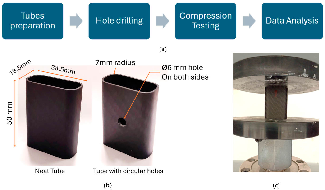
Many studies have been conducted on the crashworthiness of composites, but there is limited research on the combined effect of circular cutouts and a different stacking sequence on the crushing behavior of CFRP rectangular tubes. The interactions of these parameters and their effect on initiation, propagation, and energy-absorption characteristics of failure need to be studied to formulate design guidelines for optimized crashworthy composite structures. In contrast to previous studies, which studied stacking sequence or cutout effects independently, this work quantifies the interaction between the two conditions and identifies laminate structures that are less sensitive to geometric discontinuities. Therefore, the purpose of this study is to investigate the effect of circular cutouts on the crashworthiness behavior of CFRP rectangular tubes with different stacking sequences under quasi-static axial compression. By comparing neat tubes and tubes with circular cutouts, this work aims to clarify how laminate structures and geometric discontinuities jointly influence crashworthiness properties. The study is important because circular cutouts are often required in practical composite structures for assembly, inspection, or service integration. Understanding this interaction is essential for designing lightweight composite crash boxes that can maintain stable progressive crushing and efficient energy dissipation under crushing loading. The crashworthiness parameters, such as peak load, mean crushing load, energy absorption, specific energy absorption, and crush-force efficiency, were calculated and analyzed. The failure mechanisms of CFRP rectangular tubes with circular cutouts under different stacking-sequence configurations will be characterized.
3. Results and Discussion
This section presents and analyzes the experimental results and findings on the crashworthiness performance of CFRP rectangular tubes under quasi-static axial loading. The results are discussed in terms of Pip, Pm, EA, SEA, CFE, and failure progression. The effects of two parameters, stacking sequence and circular cutouts, were examined individually and in combination. Representative force-displacement from the quasi-static axial crushing test, failure progression, and post-test-deformed-shapes specimens are provided to support the discussion.
3.1. Failure Progression
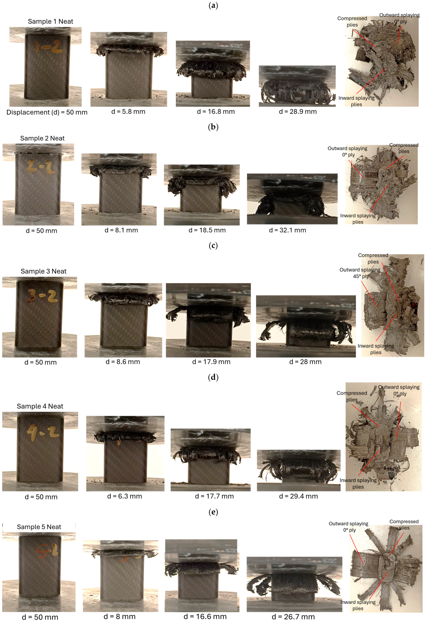
Figure 2 shows the crushing progression of neat CFRP tubes across all stacking-sequence configurations. In all cases, the crushing process initiates at the loading end, followed by progressive axial shortening accompanied by outward wall splaying. The dominant failure modes are characterized by extensive interlaminar delamination and ply separation along the tube wall, resulting in the formation of outward-bending fronds. This crushing morphology is consistent with the classical progressive-crushing behavior of composite tubes reported by Mamalis et al. [
30].
From a mechanistic point of view, the compressive load initially induces localized microbuckling and matrix cracking at the tube end, resulting in interlaminar stress concentrations at the ply interfaces. These stresses promote delamination propagation along the length of the tube, allowing individual ply or plies to delaminate and splay inwards and outwards. During crushing, a clear alternating pattern of compacted plies near the loading platen and splayed plies away from the centerline is observed, indicating a mixed mode of progressive delamination-driven fragmentation and folding.
The post-test fracture morphologies provide further evidence of the layered-laminate fragment structure of the crushed material, with clear fiber breakage, matrix cracking, and delamination. The extent and orientation of splaying vary for the different stacking sequences, implying that the interlaminar constraint and the interaction between plies are not the same. However, all neat tubes are resistant to wall instability, resulting in a crushing response dominated primarily by delamination and folding of the plies around the tube.
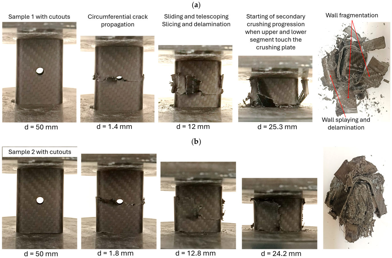
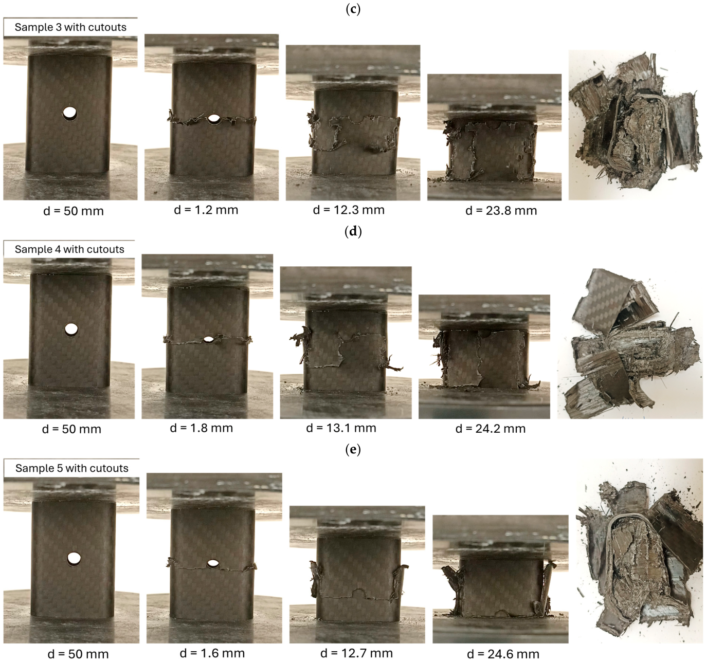
Figure 3 shows representative crushed tubes for each configuration of tube with circular cutouts. The presence of cutouts significantly influences the crushing and fracturing mechanisms compared to the neat tubes. The failure always initiates at the hole since it is a geometric stress concentrator under axial compression, not by progressive walls splaying at the end edge. Mechanistically, the presence of the hole breaks the load path in the circumferential direction and greatly reduces the local bending stiffness, leading to increased compressive and shear stresses at the periphery of the hole. This leads to premature matrix cracking, localized delamination, and circumferential crack propagation around the tube wall. As the axial loading increases, the damage becomes localized in a band of circumferential buckling around the hole. The Figure shows representative crushed tube specimens for each tube configuration with holes, dividing the tube into apparent upper and lower segments. During crushing, sliding between these segments occurs, with wall slicing and delamination, until contact with the compression plate is reached. Secondary crushing is then performed by partial splaying of walls and breakage of fibers.
The global progressive crushing is prevented, and deformation is affected by relative sliding and telescoping of the upper and lower halves of the tube. This collapse mode is characterized by sliding with limited outward splaying as seen in the post-test fracture morphologies. In contrast to the neat tubes, fiber fracture is limited to a narrow zone close to the hole, and laminate splaying is limited to secondary crushing, indicating a transition from distributed progressive crushing to localized instability-driven failure. This collapse sequence is the same for all stacking configurations, which means that the hole has a strong control on the failure mode, dominating the effect of the ply orientation on the crushing progression. Similar localized micro-buckling, tube segmentation, and sliding behavior of composite tubes with holes under axial loading have been reported in our previous work [
31].
3.2. Effect of Stacking Sequence and Circular Cutouts
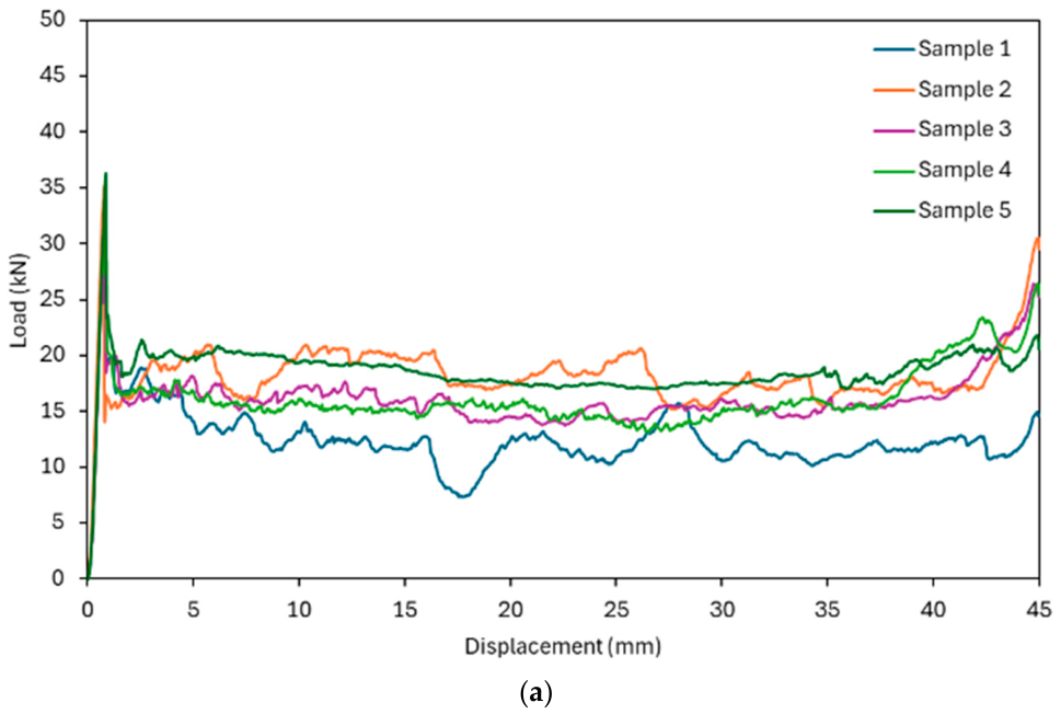
Figure 4a shows the typical force-displacement responses for five different laminate stacking sequences of neat tubes. The stacking sequence is found to be an important factor affecting the crushing behavior, load stability, and energy-absorption performance of the CFRP tubes. In general, all samples exhibit a progressive-crushing response after the initial peak load, suggesting controlled damage evolution rather than abrupt catastrophic failure.
The corresponding crashworthiness indicators extracted from these curves are summarized in
Table 2, where the values are reported as mean ± standard deviation based on three repeated tests. These quantitative results provide a clear comparison of the influence of stacking sequence on key performance metrics, including P
ip, P
m, EA, SEA, and CFE.
For the neat tubes, Samples 2 and 5 exhibit the most stable and sustained load-displacement responses, which correspond to their superior energy-absorption performance. On the contrary, Sample 1 exhibits clear load fluctuations and lower average crushing loads, reflecting the lowest crushing performances. The high crashworthiness performance of Samples 2 and 5 is due to the existence of 0°/0° plies in the mid-laminate region. These plies, oriented parallel to the load direction, increase the efficiency of axial-load transfer, encourage stable progressive crushing, and postpone premature global failure. The presence of fiber-controlled failure mechanisms, such as fiber fracture, splaying, and progressive fragmentation, leads to more stable force-displacement curves and enhanced energy absorption. On the other hand, the absence of 0°/0° plies in the mid-section of Sample 1 leads to less stable crushing, thereby reducing energy-absorption efficiency.
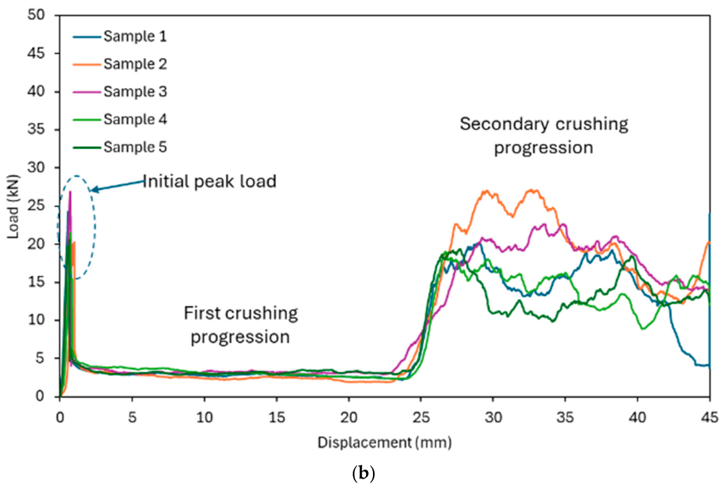
On the other hand, a significantly different crushing response is observed for tubes with circular cutouts. Direct comparisons with the neat tubes show that the introduction of circular cutouts lowers the progression crushing force. The introduction of the circular cutouts significantly reduces the initial peak load and the crushing progression load for all stacking configurations. The tubes with cutouts, as shown in
Figure 4b, after the initial collapse, exhibit a prolonged low-load region, followed by a delayed load rise at larger displacements. Such behavior may indicate that premature micro-buckling and damage initiation around the cutout area are occurring due to stress concentration and the breaking of the load-bearing fibers’ continuity. However, the degree of this degradation is highly dependent on the stacking sequence. In the initial crushing stage, during sliding of the upper and lower segments of the tubes, where up to approximately 25 mm of displacement, the force response remains comparable. However, a secondary crushing stage is initiated when the upper and lower segmented tubes come into contact with the crushing plate (
Figure 3), resulting in an increased force response that varies across configurations. Samples 2 exhibit relatively higher force responses than the other configurations during secondary crushing, suggesting that laminate designs with mid-plane 0°/0° plies are more effective at reducing the negative effects of geometric discontinuities.
At large displacement levels (approximately 45 mm), the neat tubes exhibit a noticeable increase in load, indicating the onset of densification stage. In contrast, this load increase is not observed in tubes with circular cutouts, where the force response remains relatively stable or does not show a significant rise at the same displacement level. This behavior can be explained by the difference in crushing mechanisms between the two configurations. In neat tubes, progressive crushing leads to continuous folding, splaying, and accumulation of fragmented material near the loading platen. As deformation proceeds, the crushed material becomes increasingly compacted, reducing internal voids and increasing contact resistance. In contrast, tubes with cutouts undergo localized failure dominated by sliding, segmentation, and limited folding. The presence of the cutouts disrupts the continuity of the structure and prevents uniform accumulation of crushed material. Instead of progressive material buildup, the structure deforms through relative motion between segments, with limited compaction. As a result, the densification phase is suppressed, and the corresponding load increase observed in neat tubes at large displacements does not occur in the cutout configurations.
3.3. Initial Peak Load
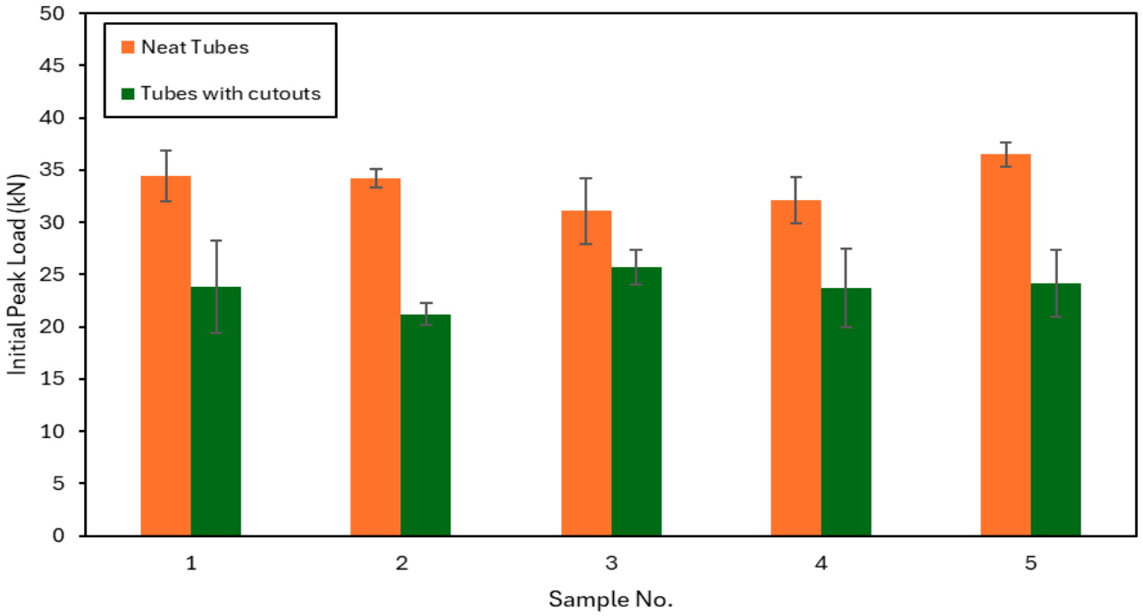
Figure 5 shows the initial peak load for neat tubes and tubes with circular cutouts for all five samples. The presence of the cutouts results in a reduction in the P
ip relative to the neat tube across all configurations. The neat tubes have peak loads of 31–37 kN, whereas the tubes with cutouts present lower values of 21–26 kN. Maximum load reduction is 20–40%, depending on the sample setup. Sample 2 shows the maximum reduction and the minimum in P
ip, from 34 kN for the neat tube to 21 kN for the tube with cutouts, a reduction of almost 40%. On the other hand, Sample 3 had the smallest reduction and the highest P
ip. The peak load decreased from 31 kN to approximately 25 kN, which is a reduction of about 20%.
The initial peak load corresponds to the onset of structural instability and the transition from elastic deformation to irreversible damage in the composite structure. At the early stage of loading, the CFRP tube behaves elastically, with the applied load increasing approximately linearly due to the global stiffness of the laminate. As the compressive stress reaches a critical level, localized instability is initiated, marking the occurrence of the initial peak load [
32]. The magnitude of this peak is governed by a combination of interacting failure mechanisms, including local buckling of the tube wall, matrix cracking, fiber kinking and fracture, and interlaminar delamination. In particular, fibers aligned in the loading direction (0° plies) play a dominant role in carrying axial load and delaying failure initiation, resulting in higher peak loads [
33]. Once these fibers or the surrounding matrix reach their failure limits, localized damage rapidly propagates, leading to a sudden drop in load and the onset of progressive crushing.
However, in the present study, all neat-tube configurations exhibit relatively similar initial peak loads. This can be attributed to the fact that the overall laminate composition and fiber orientations are comparable among the different configurations, with variations limited to the stacking-sequence order. As a result, the global axial stiffness and load-carrying capacity remain similar across the specimens, leading to comparable levels of critical stress at which instability is initiated. Therefore, the initial peak load is not significantly affected by stacking-sequence variations in this case, but is primarily governed by the overall laminate composition and structural geometry.
For neat tubes, the continuity of the laminate allows for a more uniform stress distribution and higher resistance to initial failure, resulting in a higher initial peak load. In contrast, the presence of circular cutouts introduces stress concentrations and disrupts the load-transfer path, leading to premature damage initiation. Localized stress concentration around the cutout edges promotes early matrix cracking, fiber kinking, and micro-buckling, reducing the load required to trigger instability. Consequently, the initial peak load is significantly lower in tubes with cutouts compared to neat configurations.
Moreover, the error bars indicate moderate variation in the measured Pip, with somewhat greater scatter observed in some cutout samples, suggesting greater sensitivity to local imperfections and damage evolution in the vicinity of the discontinuity.
In some cases, the observed reductions in peak load can be interpreted as a beneficial triggering effect. This is because lower initial peak forces reduce the risk of catastrophic load transmission to adjacent structures [
34,
35]. In energy-absorbing structures, excessively high peak loads are undesirable because they correspond to abrupt force transmission to adjacent components, such as vehicle frames or occupants. This sudden load transfer can cause localized damage or safety risks. A smoother transition from the initial peak loading phase to progressive crushing reduces force spikes and improves load distribution over displacement. Consequently, the structure absorbs energy in a more stable and controlled manner, reducing the likelihood of catastrophic failure and enhancing overall crash-safety performance.
3.4. Mean Crushing Load
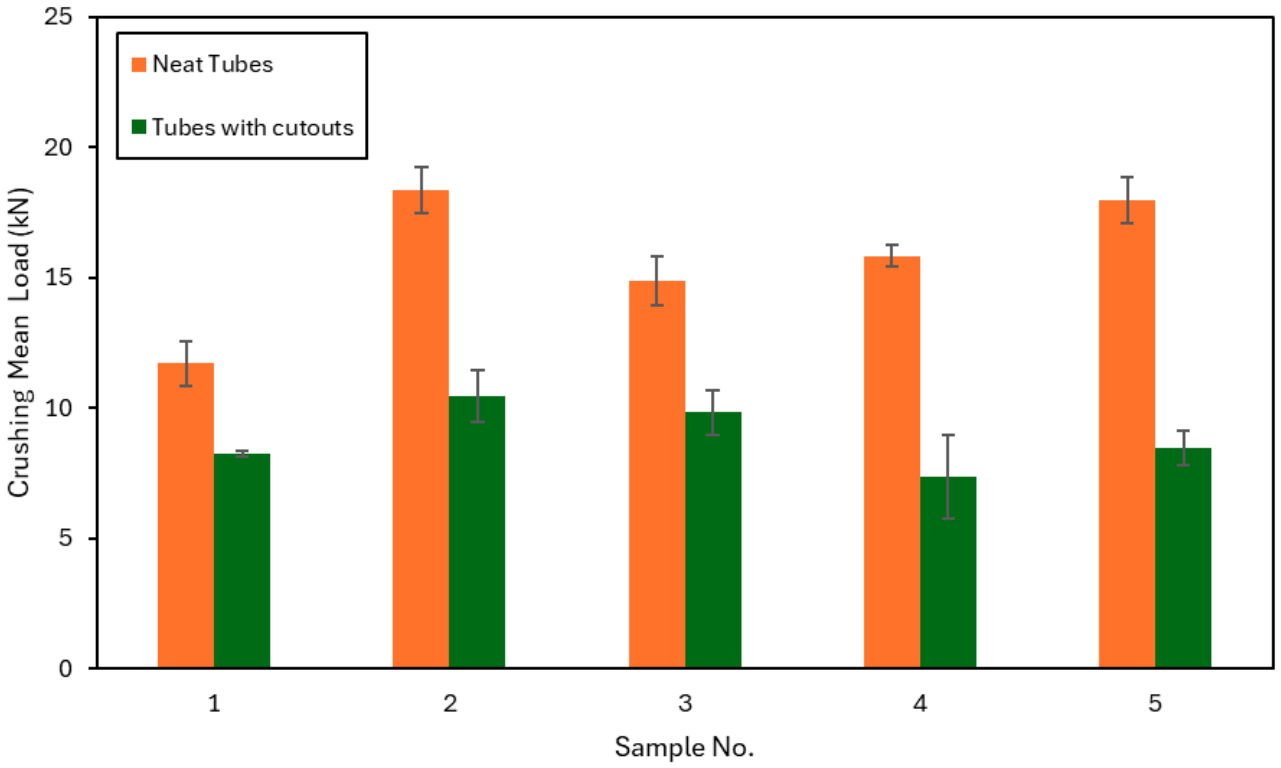
Figure 6 compares the mean crushing load for the neat tubes and the tubes with circular cutouts for all five samples. The mean load of neat tubes is always higher than that of tubes with cutouts, following the same trend as the peak load. The neat tubes have an average load of between 11 and 19 kN, whereas the tubes with cutouts have lower values, between 8.5 and 10.5 kN. In general, the mean load reduction is significant, which means that the holes weaken the capacity of the sustained load-carrying during progressive crushing. In the neat configuration, Sample 2 has the highest mean load (19 kN) while Sample 1 has the lowest (11 kN).
For the tubes with cutouts, Samples 2 and 3 exhibit the maximum average mean crushing load (10.5 kN and 9.8 kN), respectively, suggesting relatively stable crushing behavior despite the geometrical discontinuity. Sample 4, on the other hand, exhibits the lowest mean load (8.5 kN) and, hence, is more sensitive to the hole’s presence. The reduction in mean load is more obvious and consistent across all configurations than the peak-load results. The reduction in mean load was attributed to a change in crushing behavior from wall splaying and delamination to sliding. As the mean load represents the general progressive-crushing resistance and energy-absorption ability, the results indicate that the circular cutouts reduce the mean load and the structural stability during the crushing process.
3.5. Energy Absorption
Figure 7 shows the comparison of total EA for neat tubes and tubes with circular cutouts for all five samples. It is clear from this study that the neat samples have better energy-absorption characteristics compared to the corresponding perforated tubes, which is similar to the trend observed for P
m. The energy absorbed of the neat tubes is in the range of about 520 J to 800 J and the tubes with cutouts have lower values in the range of about 320 J to 460 J. This indicates a drastic reduction in crash-energy absorption as a result of the existence of circular cutouts. Sample 2 exhibits the highest energy absorption (800 J) in the neat configuration. Sample 5 demonstrates the second highest energy absorption (790 J) and shows better progressive-crushing stability than the other three samples. The lowest amount of energy absorbed by the neat tubes is for Sample 1, with 520 J.
Sample 2, with 460 J for the tubes with cutouts, shows the highest energy absorption, while the lowest value of 320 J is shown by Sample 4, which suggests that this configuration is the most sensitive to structural discontinuity. The absorbed energy loss ranges from approximately 25% to 50%, depending on the configuration, with the most significant degradation observed in Sample 4. The reduction in energy absorption is ascribed to premature damage initiation and unstable crack propagation around the hole, which restricts the progressive crushing and deteriorates the structure’s load-carrying capacity over displacement. Since the absorbed energy is directly related to the crashworthiness performance, the results show that the circular cutouts not only reduce the Pip and Pm but also significantly reduces the overall energy absorption.
3.6. Specific Energy Absorption
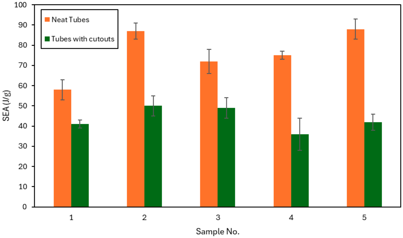
Figure 8 presents the comparison of the SEA between the neat tubes and the tubes with circular cutouts for all five samples. In agreement with the trends obtained for the Pm and EA, the neat specimens are characterized by much higher SEA values than the corresponding tubes with cutouts. The SEA of the neat tubes ranges from 58 J/g to 88 J/g, but the tubes with holes have lower values, typically ranging from about 36 J/g to 50 J/g. Sample 5 shows the highest SEA for the neat tube (88 J/g), followed closely by Sample 2 (87 J/g). The higher the SEA value, the more efficient it is in terms of absorbing energy per unit mass. Conversely, the clean samples in Sample 1 show the minimum SEA (58 J/g).
3.7. Crushing-Force Efficiency
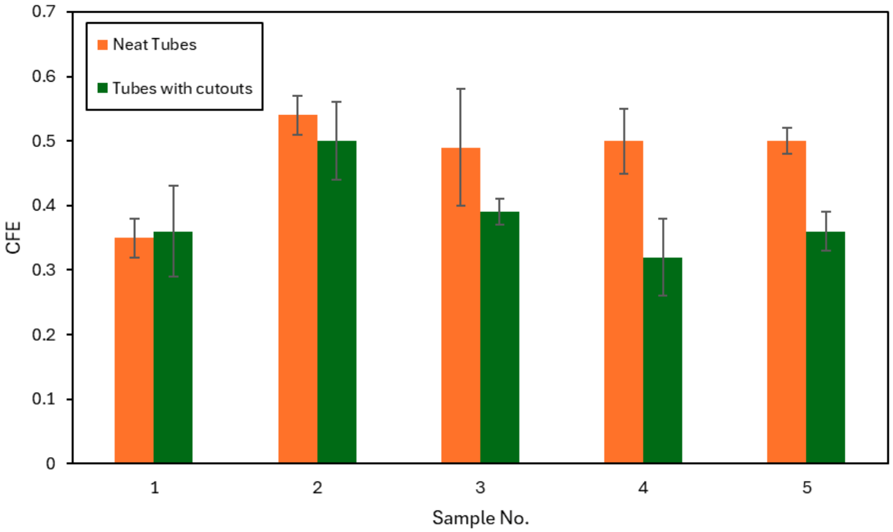
Figure 9 shows the comparison of CFE between the neat tubes and tubes with a circular cutouts for all five samples. The neat specimens show higher CFE values than those of the corresponding tubes with cutouts, having more stable and uniform crushing behavior. The CFE for the neat tubes’ ranges from about 0.34 to 0.54, and the tubes with cutouts have values ranging from about 0.32 to 0.50. Sample 2 has the highest CFE (0.54) among the neat configurations, followed by Samples 4 and 5 (0.50), reflecting the increased stability in terms of progressive crushing. By contrast, the lowest CFE (0.34) is observed for Sample 1, which suggests relatively less efficient energy absorption during deformation. For the tubes with cutouts, Sample 2 again shows the highest CFE (0.50), while Sample 4 shows the lowest (0.32), indicating that this configuration undergoes more significant load fluctuations and unstable failure after the peak load. The CFE results reveal that the circular cutouts always diminish the load-carrying capacity and energy absorption, but their influence on crushing stability is configuration-dependent.
The reduction in CFE for tubes with circular cutouts can be directly attributed to the alteration of failure mechanisms introduced by the geometric discontinuities. CFE, defined as the ratio of mean crushing load (Pm) to initial peak load (Pip), reflects the stability of the load-displacement response during progressive crushing. A higher CFE indicates a more uniform load distribution and stable energy absorption, while lower values indicate significant load fluctuations and unstable deformation.
In neat tubes, progressive crushing is characterized by stable mechanisms such as splaying, delamination, and fragmentation, which maintain a relatively consistent load after the peak. This leads to higher mean crushing loads (Pm) and, consequently, higher CFE values. In contrast, the presence of circular cutouts promotes localized damage initiation, circumferential cracking, and structural segmentation into separate regions. These mechanisms disrupt the continuity of progressive crushing and promote intermittent sliding and partial collapse rather than uniform deformation.
As a result, the load-displacement response of cutout tubes exhibits load drops following the initial peak load. This unstable post-peak response reduces the mean crushing load (P
m) significantly, while the initial peak load (P
ip) remains governed by local instability. Consequently, this leads to lower CFE values. This behavior is consistent with previous studies on perforated and triggered composite structures, which showed that geometric discontinuities induce premature damage propagation and unstable crushing, resulting in reduced crushing efficiency [
36].
3.8. Statistical Analysis
Quantitative evidence on the influence of stacking sequence on the crashworthiness performance of CFRP tubes, for both neat tubes and with circular cutout configurations, is provided by the one-way ANOVA results presented in
Table 3 and
Table 4. A main observation is that the stacking sequence does not significantly influence the P
ip in either case (
p > 0.05). This indicates that the onset of collapse is largely controlled by local instability mechanisms and geometrical features rather than by the laminate stacking sequence. The first failure for neat tubes starts at the tube edge, while for tubes with cutout it is localized at the cutout edge. In both cases, the initiation stage is dominated by stress concentration and local buckling, which reduces the relative influence of the stacking sequence. On the other hand, for neat tubes and for those with a cutout, the stacking sequence (
p < 0.05) significantly affects all the crashworthiness parameters (P
m, EA, SEA, and CFE). The laminate stacking sequence plays a dominant role in managing the progressive-crushing phase rather than the initial collapse, as clearly demonstrated here. The progressive stage involves complex damage evolution mechanisms such as delamination, fiber fracture and matrix cracking, which are highly dependent on the ply orientation, interlaminar interactions and load redistribution pathways.
The very low p-values obtained for neat tubes for Pm, EA, and SEA demonstrate a strong dependence of energy-absorption capability on stacking sequence. This is consistent with the experimental observation that the configurations with the mid-plane 0°/0° plies (Sample 2 and 5) show more stable crushing behavior and more energy dissipation. The statistical significance here is a measure of the efficiency of these laminates to sustain load through large displacements. This is directly related to their ability to promote progressive-failure mechanisms in a controlled manner.
In the case of tubes with circular cutouts, the stacking sequence is statistically important for the crashworthiness parameters, but the p-values are considerably lower than those for the neat case, where the p-values are relatively higher (but still below 0.05). This suggests that the influence of stacking sequence is reduced in the presence of geometric discontinuities. Physically, a reason for this may be the cutout’s dominant role in defining the failure mode and localizing the damage. The stress concentration caused by the hole partly overcomes the effect of the laminate structure by forcing the initiation and propagation of failure within a limited region.
However, the statistical significance of the stacking sequence in tubes with cutouts suggests that laminate design still controls the residual structural response in secondary crushing. After the initial localized failure, the ability of the structure to carry load, redistribute stresses and absorb additional energy is still determined by the internal ply configuration. Therefore, optimized stacking sequences (e.g., Sample 2) still outperform other stacking sequences, even with severe degradation.
4. Conclusions
The combined effects of laminate stacking sequence and circular cutouts on the crashworthiness of CFRP rectangular tubes under quasi-static axial crushing were systematically studied in this work. The effects of these parameters on the main crashworthiness parameters, such as initial peak load (Pip), mean crushing load (Pm), energy absorption (EA), specific energy absorption (SEA), crushing-force efficiency (CFE), and failure mechanisms, were also investigated in detail. The results reveal that the stacking sequence has a statistically significant effect on the crushing behavior and energy-absorption performance, except in terms of the Pip. Specifically, the laminates with 0°/0° plies at the mid-plane (Sample 2 and Sample 5) show better crashworthiness due to the better axial-load transfer, higher structural stability, and more efficient progressive-crushing mechanisms. The presence of circular cutouts causes early failure initiation and changes the failure mode. In contrast to the progressive delamination and splaying of neat tubes, tubes with cutouts exhibit a characteristic two-stage crushing response. In the first stage, failure mechanisms are localized, and involve such things as circumferential cracking, axial sliding, and structural segmentation, while in the second stage, limited delamination and splaying occur. Such a transition from distributed progressive crushing to localized micro-buckling results in a drastic reduction in all crashworthiness indicators, with energy absorption decreasing by up to 50%, depending on the stacking configuration. Furthermore, the cutout sensitivity is highly influenced by the laminate stacking sequence. Although Sample 2 has a higher initial performance and a higher relative degradation, it still provides better crashworthiness than other configurations in perforated conditions. This result shows that optimized stacking sequences can partially mitigate the detrimental effect of geometric discontinuities. The results in general point out the need for an integrated design methodology for composite crashworthy structures. The strategic design of the laminate stacking sequences and control of the geometric discontinuities can significantly improve the crashworthiness performance of CFRP tubes for lightweight structural applications. Future work will focus on the development of finite-element models to further investigate stress distribution, failure evolution, and the interaction between stacking sequence and geometric discontinuities.