1. Introduction
Bridges are critical components of national infrastructure and play a vital role in supporting economic activity. In the United States, there are approximately 617,000 bridges, of which 46,154 (7.5%) are classified as structurally deficient [
1], while approximately 42% are at least 50 years old. These aging and deficient structures accommodate an estimated 178 million vehicle crossings daily, underscoring the urgency of the problem. The nationwide backlog of bridge repairs is currently estimated at
$125 billion, and addressing this deficit would require increasing annual investment in bridge maintenance from
$14.3 billion to
$22.6 billion, representing a 58% increase. At the current funding level, necessary repairs are not expected to be completed until 2071, during which time continued deterioration will further exacerbate existing deficiencies. These challenges highlight the urgent need for a coordinated national rehabilitation strategy, similar to successful programs implemented in some states, with a strong emphasis on preventive maintenance and prioritized repair efforts [
1].
Corrosion is the primary cause of structural deterioration in steel bridges [
2]. These structures are exposed to harsh environmental conditions, resulting in varying degrees of corrosion across different components depending on their level of exposure. Corrosion occurs due to chemical reactions between steel and its surrounding environment and is often accelerated by moisture ingress, water leakage through deck joints, and the application of deicing chemicals in cold regions [
3]. Consequently, corrosion is prevalent in steel multi-girder bridges, particularly at girder ends and along the lower web regions. In severe cases, it can lead to significant section loss and even separation between the lower web and bottom flange over several meters near the girder ends [
4].
An analysis of bridge failures in the United States from 1988 to 2012 by Lee et al. [
5] reported a total of 1062 bridge failures, with nearly 65% occurring in steel bridges. These failures accounted for approximately 85% of similar incidents worldwide, highlighting the vulnerability of steel bridge systems. In addition to the degradation of main longitudinal steel girders, the serviceability, cracking limits, and structural durability of bridge substructure components, such as columns and piers, represent critical safety concerns that govern the overall lifecycle of aging infrastructure [
6,
7]. This finding underscores the urgent need to improve the understanding and prediction of the service life of existing steel bridges. Corrosion-induced degradation in steel plate girder bridges can significantly reduce load-carrying capacity under various loading conditions, increasing the risk of structural failure, particularly when critical primary girders are affected. Steel plate girders are typically fabricated as built-up I-shaped sections, with girder ends and the intersection of the bottom flange and web being the most susceptible regions to corrosion [
8].
Significant research has been conducted to evaluate the effects of corrosion on structural performance. Tzortzinis et al. [
9] investigated naturally corroded girders to assess the accuracy of strength evaluation methods for unstiffened rolled I-beams. Sugimoto et al. [
10] examined a century-old railway deck plate girder and proposed a methodology to estimate reductions in flexural and shear capacity due to corrosion. Ahn et al. [
11] demonstrated that pitting corrosion can significantly influence shear buckling behavior once it exceeds a critical threshold. Sheng et al. [
12] developed a neural network-based model to predict the flexural capacity of corroded beams, showing that capacity decreases with increasing corrosion duration and load ratio. Liu et al. [
13] experimentally evaluated corroded Q550E steel beams and reported that each 1% increase in corrosion ratio resulted in an approximate 11 kN reduction in both yield and ultimate loads. Usukura et al. [
14] and Tohidi [
15] employed finite element analysis to investigate sensitivity, failure mechanisms, and residual capacity in corroded plate girders. Due to the highly irregular nature of corrosion patterns, Nakai [
16] studied artificial pitting in girder webs and demonstrated that pit configuration has a significant influence on web failure behavior.
Different forms of corrosion can develop in steel bridges, with pitting and uniform corrosion being the most common. Gomaa et al. [
17] investigated the effects of environmental conditions, including chloride concentration and temperature, on the initiation and propagation of corrosion in steel plates subjected to tensile loading, simulating conditions similar to those in the lower flange of simply supported steel beams. Their results showed that pitting corrosion can initiate even at relatively low chloride concentrations and that the associated strength reduction observed in uniaxial tension tests is more pronounced due to the formation of corrosion pits. Using finite element analysis, they further demonstrated that corrosion pits in steel plates can be realistically represented using a random distribution model that reflects the observed weight loss [
18]. However, these studies were limited to dog-bone specimens subjected to uniform tensile stress, highlighting the need for further investigation of corrosion behavior and capacity degradation in full-scale steel beams.
Given the aging condition of steel and concrete bridges, corrosion-related deterioration necessitates regular maintenance and rehabilitation [
3]. Various rehabilitation and strengthening approaches have been investigated in the literature. Monteiro et al. [
19] examined repair procedures for steel bridges with non-weldable components and riveted connections, including member straightening, gusset plate replacement, and the installation of new rivets. Mitra et al. [
20] proposed the use of basalt fiber fabrics to strengthen steel I-beams with compression flange corrosion, demonstrating a sustainable retrofit solution. Mohammadzadeh et al. [
21] conducted a numerical study on preloaded steel I-beams strengthened with welded cover plates and reported significant improvements in ultimate capacity and stiffness, along with effective prevention of lateral torsional buckling. Shen et al. [
22] investigated the flexural behavior of UHPC I-beams reinforced with steel plates through both experimental testing and numerical analysis. Their results showed that replacing steel reinforcement with 3 mm thick steel plates effectively limited crack propagation and increased yield and ultimate loads.
One effective rehabilitation technique for corroded steel bridges is the use of ultra-high-performance concrete (UHPC). UHPC is an advanced class of cementitious materials characterized by superior compressive strength [
23,
24,
25,
26]. When reinforced with steel fibers, it also exhibits enhanced tensile and flexural capacities [
7,
27], making it a promising material for bridge rehabilitation applications. Mash et al. [
28] utilized UHPC to improve the shear capacity of corroded steel webs in support regions by casting UHPC around the web from both sides. Although this method increased shear capacity, it did not prevent further corrosion at the steel–UHPC interface. In addition, the use of UHPC in this manner increased the overall dead load of the beam. Similar studies have applied the concept of encasing corroded beam ends with UHPC for rehabilitation [
29,
30]; however, these approaches exhibit similar limitations.
From the above studies, it is evident that two primary methods are commonly used for rehabilitating corroded steel beams: strengthening with welded steel plates and encasing deteriorated regions with UHPC. The first method is costly, labor-intensive, and difficult to implement under field conditions, while the second introduces several drawbacks, including increased dead load and the inability to prevent continued corrosion at the steel–UHPC interface, which may ultimately lead to premature or even catastrophic failure. In response to these limitations, this study proposes a novel rehabilitation approach that leverages the superior mechanical and durability properties of UHPC. The proposed method involves replacing the deteriorated bridge deck slab, typically composed of normal strength concrete (NSC) and replaced approximately every 40 years [
31], with a thinner and lighter UHPC slab. This approach reduces dead load and enhances the global structural behavior of corroded beams without requiring modifications to the steel girder. In addition to its high strength, UHPC offers exceptional durability due to its very low permeability, providing a maintenance-free service life that can exceed 100 years even in aggressive environments [
32].
In addition to the slab replacement strategy, a combined rehabilitation method is investigated to evaluate the potential benefits of integrating UHPC slab replacement with welded steel plate strengthening of the corroded lower flange. The study considers key parameters including concrete type (NSC and UHPC), corrosion type (pitting and uniform), and beam span lengths (5 m, 7 m, and 9 m). Three levels of pitting corrosion were considered, with pit depths of 2 mm, 5 mm, and 8 mm, corresponding to local thickness reductions of 10%, 25%, and 40% at the pit locations. For uniform corrosion, three levels (10%, 25%, and 40%) were examined and modeled as a uniform percentage reduction in flange thickness. These investigations are carried out using detailed finite element analysis of corroded steel–concrete composite beams and are complemented by a theoretical case study that examines the application of the proposed method to a corroded non-composite steel bridge in Pennsylvania. The structural performance of the beams is evaluated under intact, corroded, UHPC-rehabilitated, and combined UHPC-rehabilitated and steel plate-strengthened conditions.
2. Finite Element Modeling
Finite element modeling was employed to investigate the structural behavior of corroded steel–concrete composite beams and to evaluate the effectiveness of the proposed rehabilitation strategies. The developed models were based on fully shear-connected composite steel I-beams to accurately represent composite action between the steel girder and the concrete slab. The numerical simulations were designed to capture the nonlinear response of the beams under monotonic loading. Both NSC and UHPC slabs were considered to assess the influence of concrete type on structural performance. The models represent intact, corroded, and rehabilitated conditions, including UHPC slab replacement and combined UHPC slab replacement with steel plate strengthening. All finite element analyses were conducted using the nonlinear analysis software ABAQUS/CAE version 6.7. [
33].
2.1. Material Properties
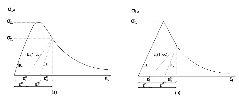
This study employs the concrete damage plasticity (CDP) model to simulate the behavior of both NSC and UHPC due to its unique ability to combine isotropic damaged elasticity with tensile and compressive plasticity. For NSC, the stress–strain relationships in tension and compression are defined according to the CDP model based on established formulations in the literature [
34,
35], as illustrated in
Figure 1. The corresponding plasticity parameters adopted in the model are summarized in
Table 1.
The CDP model incorporates damage variables to represent stiffness degradation under loading. Two scalar damage factors are defined for compression (dc) and tension (dt), as expressed in Equation (1). These parameters range from 0 to 1, where a value of 0 represents undamaged material and a value of 1 indicates complete loss of load-carrying capacity.
Table 1 summarizes the plasticity parameters adopted in the model. In the CDP formulation,
Ψ represents the dilation angle in degrees,
ϵ denotes the eccentricity,
μ represents the viscosity parameter,
kc is the ratio of the second stress invariant on the tensile meridian to that on the compressive meridian, and
σbo/σco corresponds to the ratio of the initial equibiaxial compressive yield stress to the initial uniaxial compressive yield stress.
For UHPC, Jian and Zhi [
36] investigated its uniaxial compressive behavior and proposed a constitutive relationship for uniaxial compression, as expressed in Equation (2).
In this formulation,
represents the compressive strength of UHPC, taken as 131.1 MPa. The variable
denotes the stress ratio, defined as
, where
is the strain corresponding to the peak compressive strength of UHPC, with a value of 0.0027. The parameter
represents the modulus ratio, defined as
, where
is the initial elastic modulus of UHPC, equal to 48.3 GPa, and
is the secant modulus of the UHPC stress–strain curve at peak compressive strength. The plasticity parameters adopted for the CDP model are summarized in
Table 1.
Zhe [
37] investigated the uniaxial tensile behavior of UHPC through experimental testing and proposed a corresponding constitutive relationship. The UHPC considered in this study exhibits a strain-hardening response after reaching its tensile strength [
38,
39]. The modified uniaxial tensile constitutive relationship adopted in this study is expressed in Equation (3).
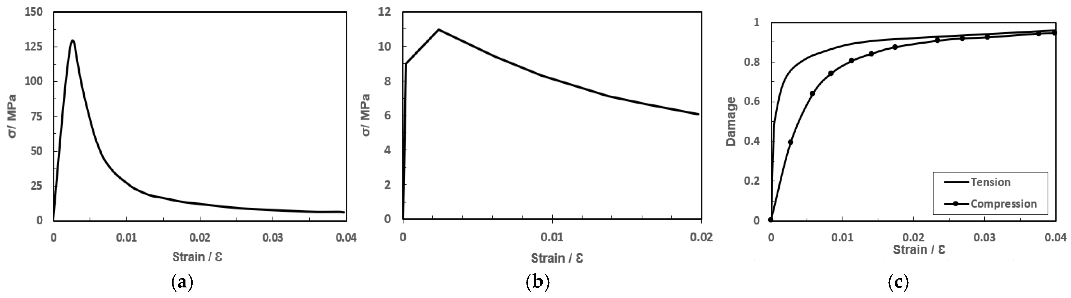
In this formulation, represents the uniaxial tensile strength of UHPC, taken as 9 MPa. The parameter is the tensile strain: denotes the elastic tensile strain, with a value of 186 μm/m, while represents the peak tensile strain in the strain-hardening phase, equal to 2500 μm/m. The parameter corresponds to the ultimate tensile strength in the strain-hardening stage, with a value of 11 MPa, as determined through linear fitting with coefficients and , where denotes the crack opening displacement, and the localized cracking relationship within the softening regime is governed by the characteristic element length (Lc), where .
To accurately capture the damage behavior of UHPC under both compression and tension, appropriate damage coefficients must be defined. Based on the work of Shao [
40], the damage evolution of UHPC is described using Equation (4). The resulting compressive and tensile stress–strain relationships, along with the corresponding damage curves, are presented in
Figure 2.
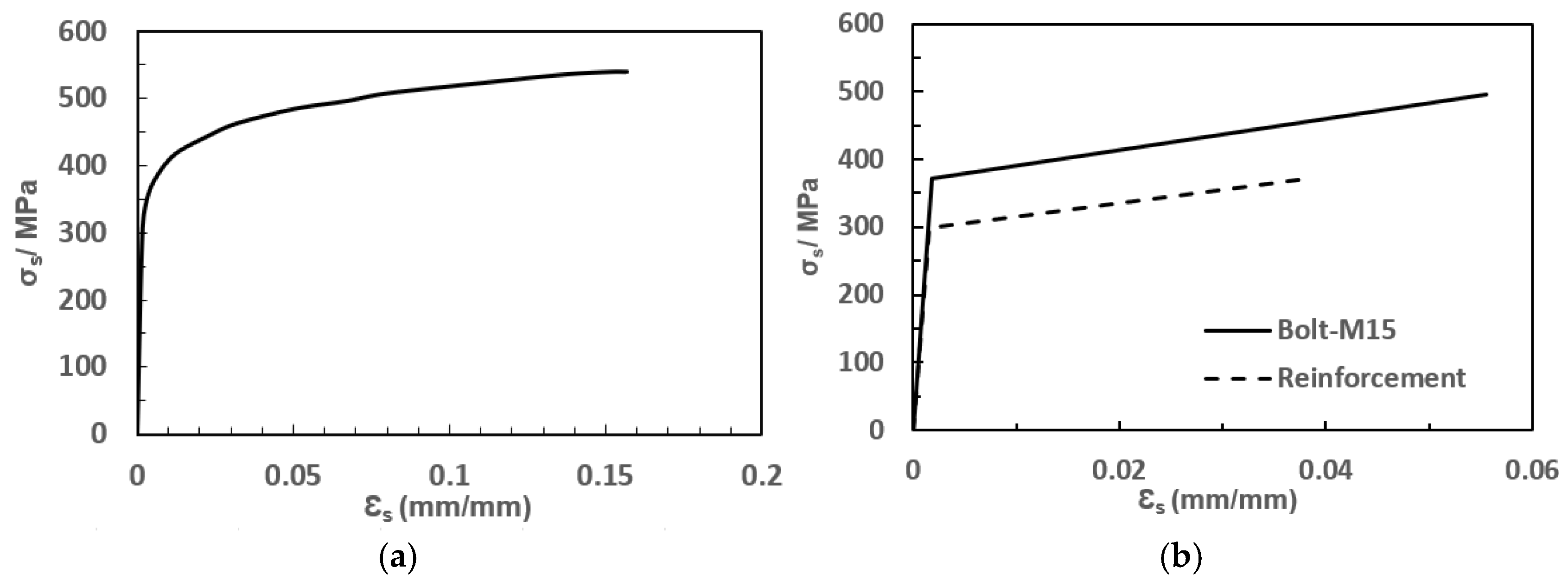
The stress–strain curves of the steel beam, reinforcing steel, and bolts are defined based on the material properties reported in [
41], as illustrated in
Figure 3. The Q345 steel beam is modeled using an elastic–plastic constitutive relationship with nonlinear strain hardening, characterized by an initial linear elastic response followed by yielding and gradual stress increase with strain. In contrast, the reinforcing steel and bolts are represented using elastic–plastic behavior with limited strain hardening. This modeling approach captures the nonlinear response of steel components under increasing load and provides an accurate representation of their contribution to the overall structural behavior.
2.2. Elements and Boundary Conditions
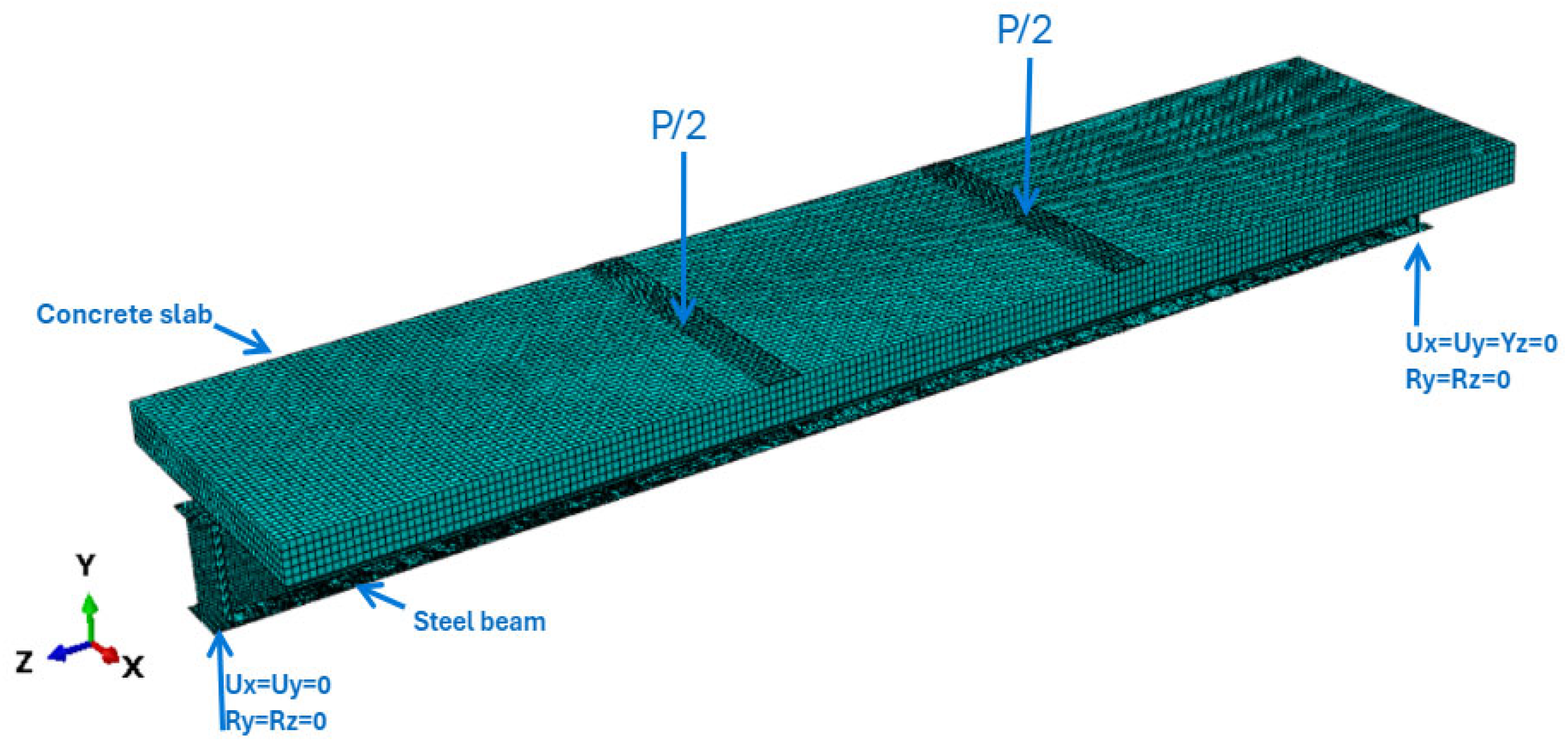
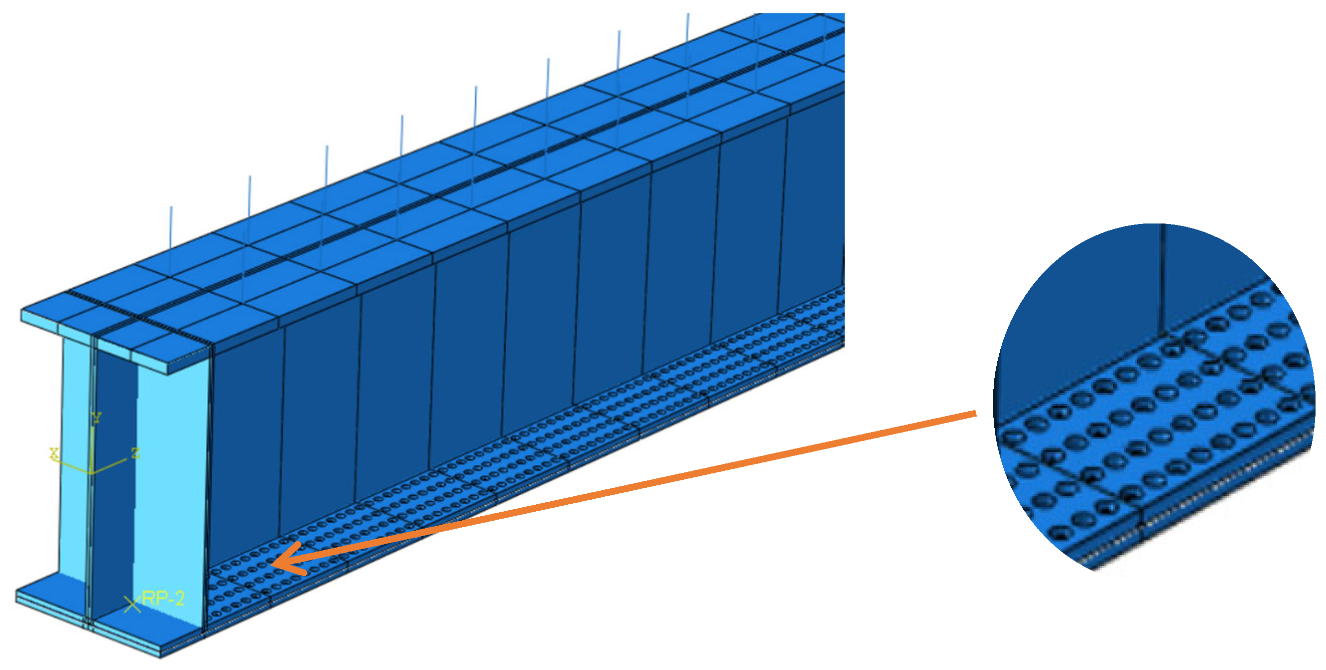
The finite element model (FEM) of the composite beam is illustrated in
Figure 4, showing the mesh discretization, loading configuration, and boundary conditions. The steel beam is modeled using four-node shell elements (S4R), while the concrete slab is represented using three-dimensional eight-node solid elements (C3D8R). A structured mesh strategy is adopted to ensure both accuracy and computational efficiency, with a mesh size of 15 mm for the steel beam and 40 mm for the concrete. The composite beam is subjected to a two-point loading configuration, where equal concentrated loads (P/2) are applied at the (1/3) span. This structural test setup was designed to create a region of pure bending between the loading points, which is characterized by the maximum constant bending moment and zero shear force. This configuration corresponds to the maximum flexural capacity, the strain-hardening effect of the UHPC, and the progressive cracking in pure flexure. Boundary conditions are defined to simulate simply supported conditions, with appropriate constraints applied at the supports to restrict translational and rotational degrees of freedom, as shown in
Figure 4. The interaction between the steel beam and the concrete slab is defined using a surface-to-surface contact formulation that accounts for both normal and tangential behavior. In the normal direction, hard contact is employed to prevent penetration between surfaces, while in the tangential direction, a penalty friction formulation is used to simulate shear interaction. The connection between the steel beam and the concrete slab is reinforced using tie constraints to ensure that the steel girder and the new UHPC slab behave as a fully monolithic composite section.
2.3. FE Meshing
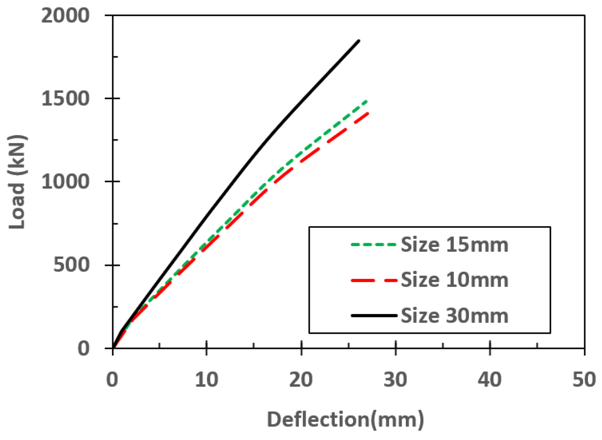
A mesh sensitivity analysis was conducted to ensure the accuracy and reliability of the finite element model. Three mesh sizes were considered for the steel beam, namely 30 mm, 15 mm, and 10 mm, to accurately capture the localized buckling and complex stress fields caused by uniform and localized pitting corrosion. On the other hand, in flexure without any chemical degradation, the mesh size for the concrete slab was kept constant at 40 mm to ensure displacement compatibility and numerical convergence and, at the same time, optimize computational efficiency. The load–deflection response of the composite beam was used as the primary criterion for evaluating mesh convergence. Convergence was assumed to be achieved when further refinement of the mesh resulted in negligible differences in the structural response.
The load–deflection response was selected as the main convergence criterion because it is a good model for the global stiffness degradation and ultimate capacity of the composite beam. The negligible difference in this curve shows that the global structural behavior and internal stress redistributions have achieved numerical stability.
As shown in
Figure 5, the load–deflection curves obtained using mesh sizes of 15 mm and 10 mm are nearly identical, indicating that the solution has converged. In contrast, the 30 mm mesh produces a stiffer response and overestimates the load-carrying capacity, demonstrating that it is insufficiently refined. Based on these observations, a mesh size of 15 mm was selected for the steel beam, as it provides an appropriate balance between computational efficiency and accuracy.
2.4. Validation of FE Model
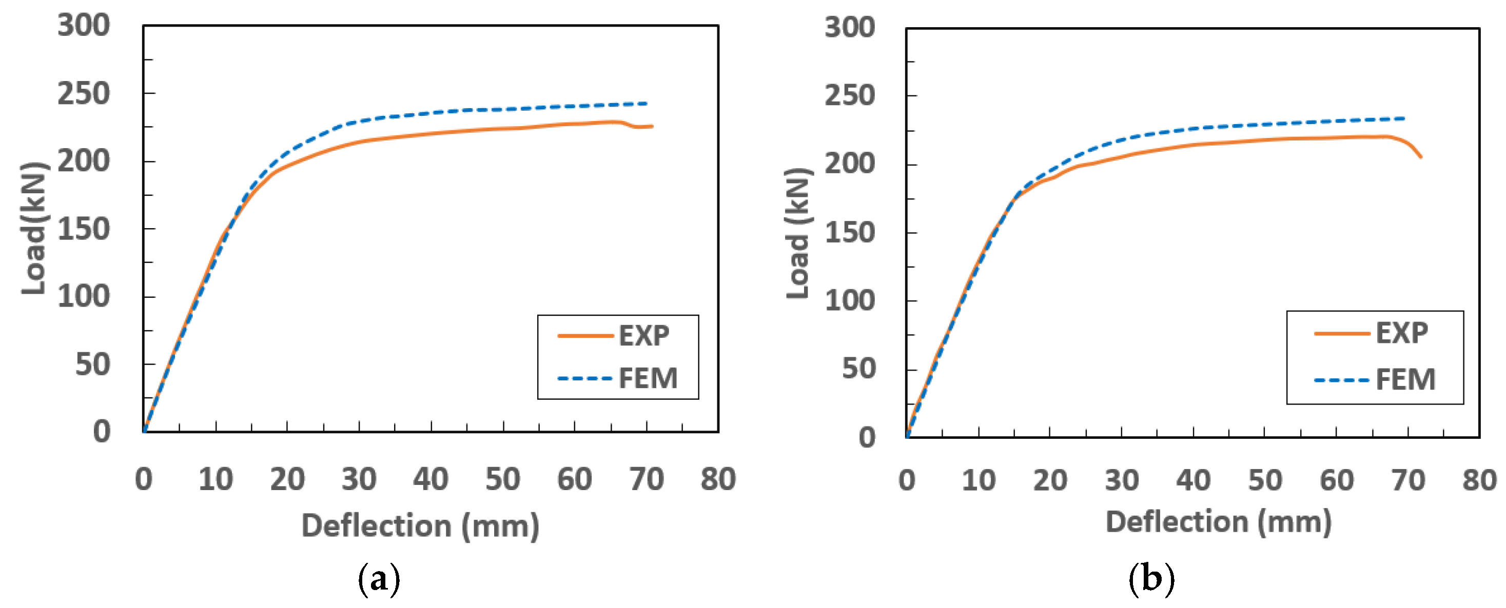
Three validation studies were conducted to assess the accuracy and reliability of the FEM in predicting the structural capacity of steel beams. The validation focused on beams with corroded lower flanges, as well as steel–NSC and steel–UHPC composite beams.
2.4.1. Validation Study 1
The experimental results reported by Mitra et al. [
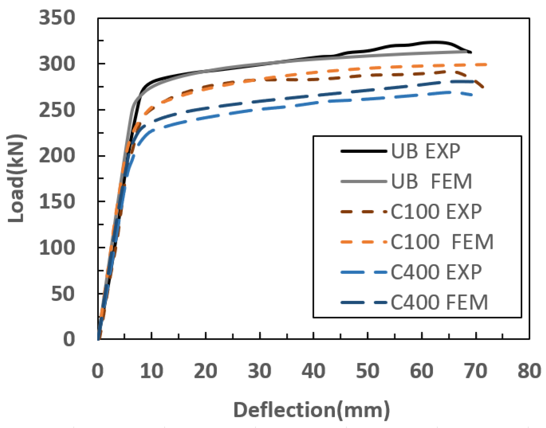
42] for wide-flange steel beams (I-shaped) were used for validation. Three beam specimens were considered. The specimen without corrosion defects is referred to as the uncorroded beam (UB), while the other two specimens exhibited corrosion damage. One specimen contained a square corrosion region measuring 100 mm × 100 mm (C100), corresponding to a corrosion aspect ratio of 1, while the other had a rectangular corrosion region measuring 400 mm × 100 mm (C400), corresponding to an aspect ratio of 4. In both cases, the corrosion depth was equal to 40% of the flange thickness.
The load–deflection responses obtained from the simulations are in good agreement with the experimental results, as presented in
Figure 6. The comparison of ultimate load capacities is summarized in
Table 2, showing that the difference between the numerical and experimental results is less than 5.40%, which confirms the accuracy of the developed FEM. While the steel material models exhibit continuous hardening at large strains (
Figure 3), the global structural response (
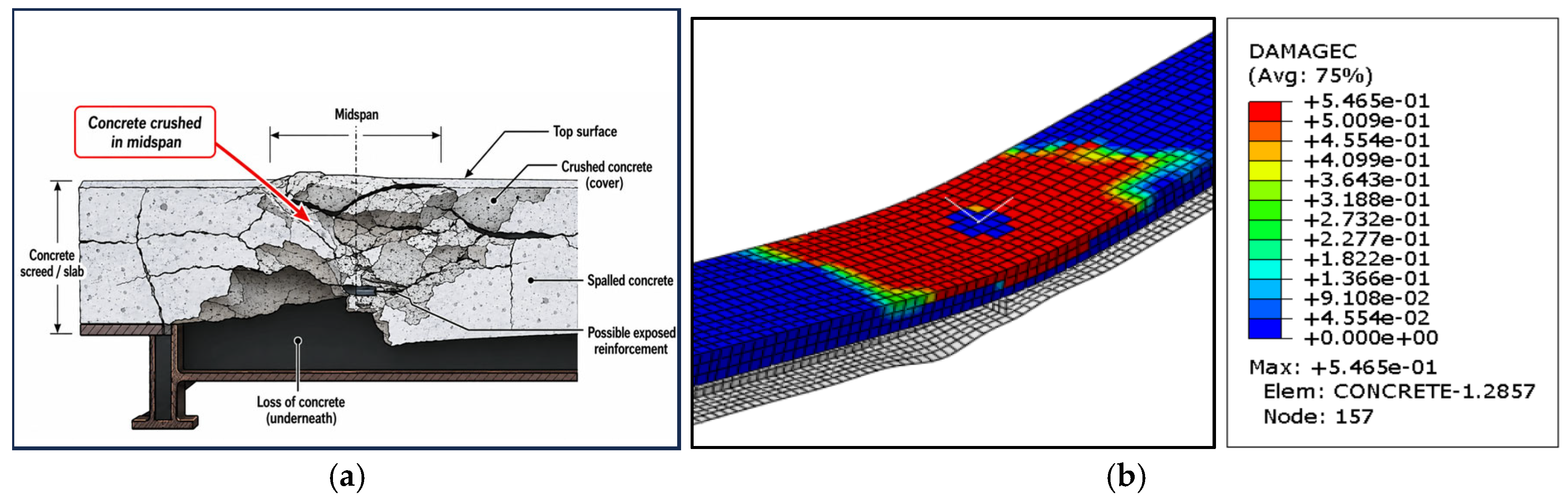
Figure 6) shows a post-peak drop. This global softening is governed by geometric nonlinearities—specifically localized buckling of the corroded steel parts and crushing of the concrete slab—rather than individual material strength degradation.
2.4.2. Validation Study 2
The FEMs were further validated against monotonic loading test results of steel–NSC beams with a span of 3 m, as reported by Wang et al. [
43]. The steel girder was fabricated from Q345 steel with a yield strength of 352 MPa, while the concrete compressive strength was determined from standard prismatic specimens, with an average value of 38.5 MPa.
The numerical model accurately captured the deformed shapes and failure modes of the steel–NSC beams under monotonic loading for the two specimens, SCB-1 and SCB-2, which had different degrees of shear connection (h = 1.0 and 0.71, respectively).
Figure 7 presents a comparison of the deformed shapes obtained from both the experimental tests and the FEM for specimen SCB-1. The load–deflection responses predicted by the finite element simulations show strong agreement with the experimental results, as illustrated in
Figure 8, for both SCB-1 and SCB-2. A comparison of the ultimate load capacities is provided in
Table 3, indicating that the difference between the numerical and experimental results is less than 6.42%, thereby confirming the reliability of the developed model.
2.4.3. Validation Study 3
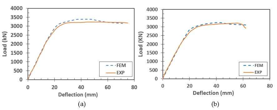
The finite element model was further validated against monotonic loading test results of high-strength steel–UHPC composite beams reported by Tong et al. [
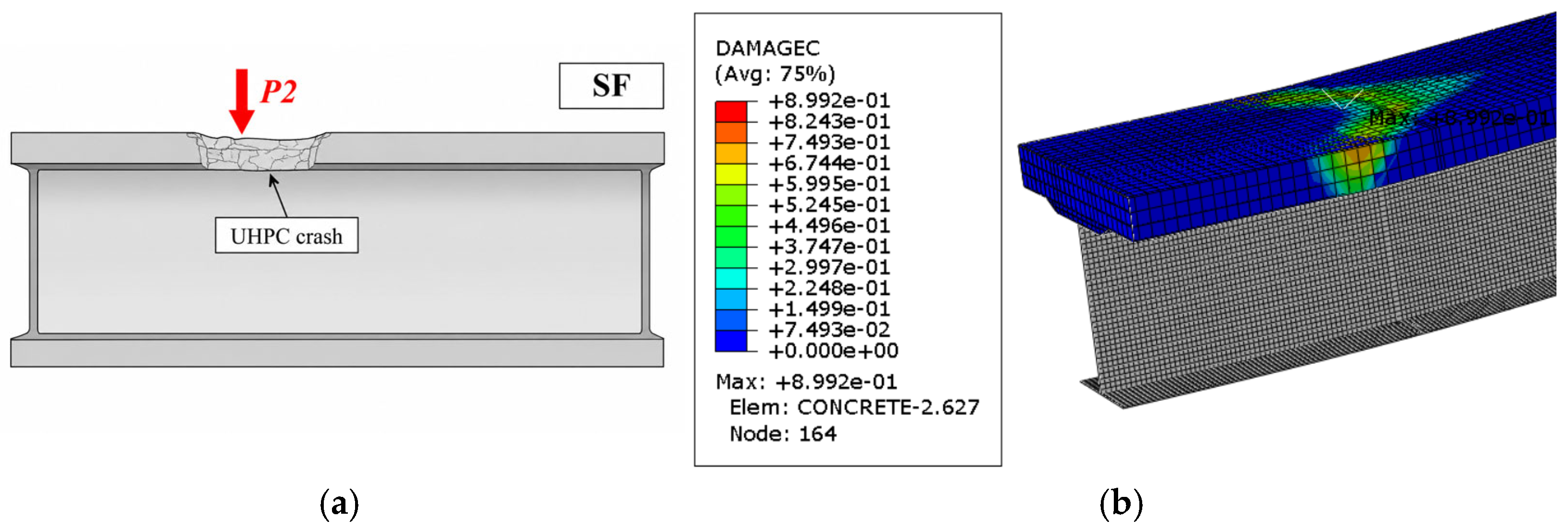
44]. The steel girder was fabricated from Q690 steel, while the UHPC exhibited a compressive strength of 131.1 MPa. The numerical model accurately captures the deformed shapes and failure modes of the composite beams for specimens with single and grouped full-shear connections (SF and GF).
Figure 9 presents a comparison between the experimental and finite element failure modes for specimen SF.
The load–deflection responses obtained from the finite element simulations show good agreement with the experimental results, as illustrated in
Figure 10. A comparison of the ultimate load capacities is summarized in
Table 4, indicating that the difference between the numerical and experimental results is less than 5.6%, thereby confirming the accuracy and reliability of the developed model.
3. Parametric Studies
3.1. Specimens’ Geometric and Model Description
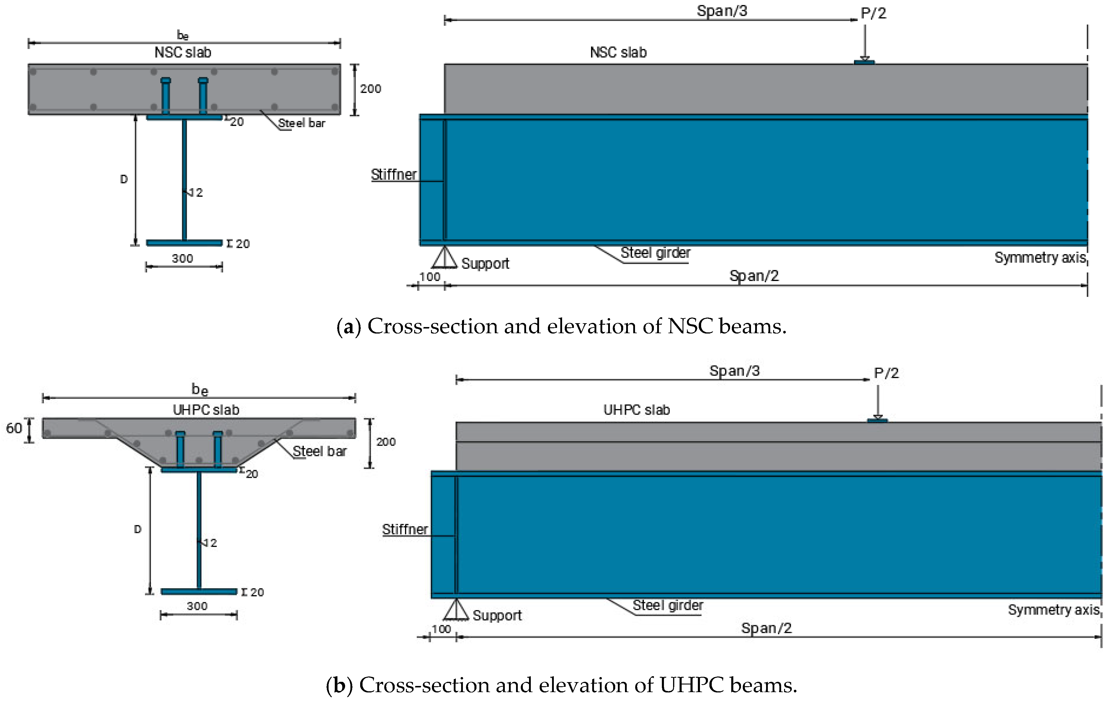
Finite element analysis was conducted to investigate the structural performance of steel–NSC and steel–UHPC composite beams with corroded lower flanges. Three span lengths of 5, 7, and 9 m were considered, with corresponding cross-sectional configurations, as illustrated in
Figure 11. The geometric properties of each section are summarized in
Table 5.
Two common types of corrosion, namely uniform corrosion and pitting corrosion, were considered in this study. Corrosion was simulated by reducing the thickness of the lower flange. For the study of pitting corrosion, defects were represented as cylindrical pits with a diameter of 15 mm, as illustrated in
Figure 12, and based on experimentally obtained pit dimensions [
3]. The mid-plane of the lower flange was kept unchanged, meaning that corrosion was assumed to occur symmetrically on both sides of the flange. Three levels of corrosion, 10%, 25%, and 40%, were considered for each corrosion type, where the corrosion level represents the percentage reduction in flange thickness.
The reduction in flange thickness due to corrosion leads to a decrease in the load-carrying capacity of composite beams. To address this issue, a rehabilitation approach is adopted by replacing the conventional NSC slab with a thinner UHPC slab, taking advantage of the superior mechanical properties of UHPC. This allows for a reduction in slab thickness while achieving enhanced structural performance, ultimately decreasing the overall self-weight of the bridge. The reduction in dead load can partially compensate for the loss of capacity caused by corrosion. This approach is consistent with the findings of [
3], which demonstrated the feasibility of reducing the UHPC slab thickness to approximately half that of an NSC slab while restoring the structural capacity to safe levels. However, that study was limited to a proof-of-concept investigation. In the present work, this concept is further explored through an extensive parametric study while maintaining the same steel beam geometry, as illustrated in
Figure 11. In addition, a strengthening technique is considered by welding steel plates with a thickness of 6 mm to both the top and bottom surfaces of the corroded lower flange in order to further enhance the structural performance of the composite beams.
The introduction of corrosion led to a reduction in the load-carrying capacity of the beams. To mitigate this reduction, a rehabilitation strategy was implemented by replacing the NSC slab with a UHPC slab for all corroded specimens, resulting in 18 rehabilitated specimens. Furthermore, a strengthening technique was applied by welding steel plates with a thickness of 6 mm to both the top and bottom surfaces of the lower flange for all UHPC-rehabilitated beams, yielding an additional 18 strengthened specimens. In total, 57 specimens were analyzed in this study.
Each specimen was assigned a unique identification code. In this notation, “S” denotes the beam span; “NC” represents NSC; “UH” represents UHPC; “UC” and “PC” denote uniform and pitting corrosion, respectively; and “CL” indicates the corrosion level. The suffix “+PL6mm” indicates the addition of welded steel plates with a thickness of 6 mm to the lower flange. For example, the specimen code “S5-UH-UC-CL10% + PL6mm” represents a 5 m span beam with a UHPC slab, uniform corrosion at a 10% level, and additional strengthening using welded plates.
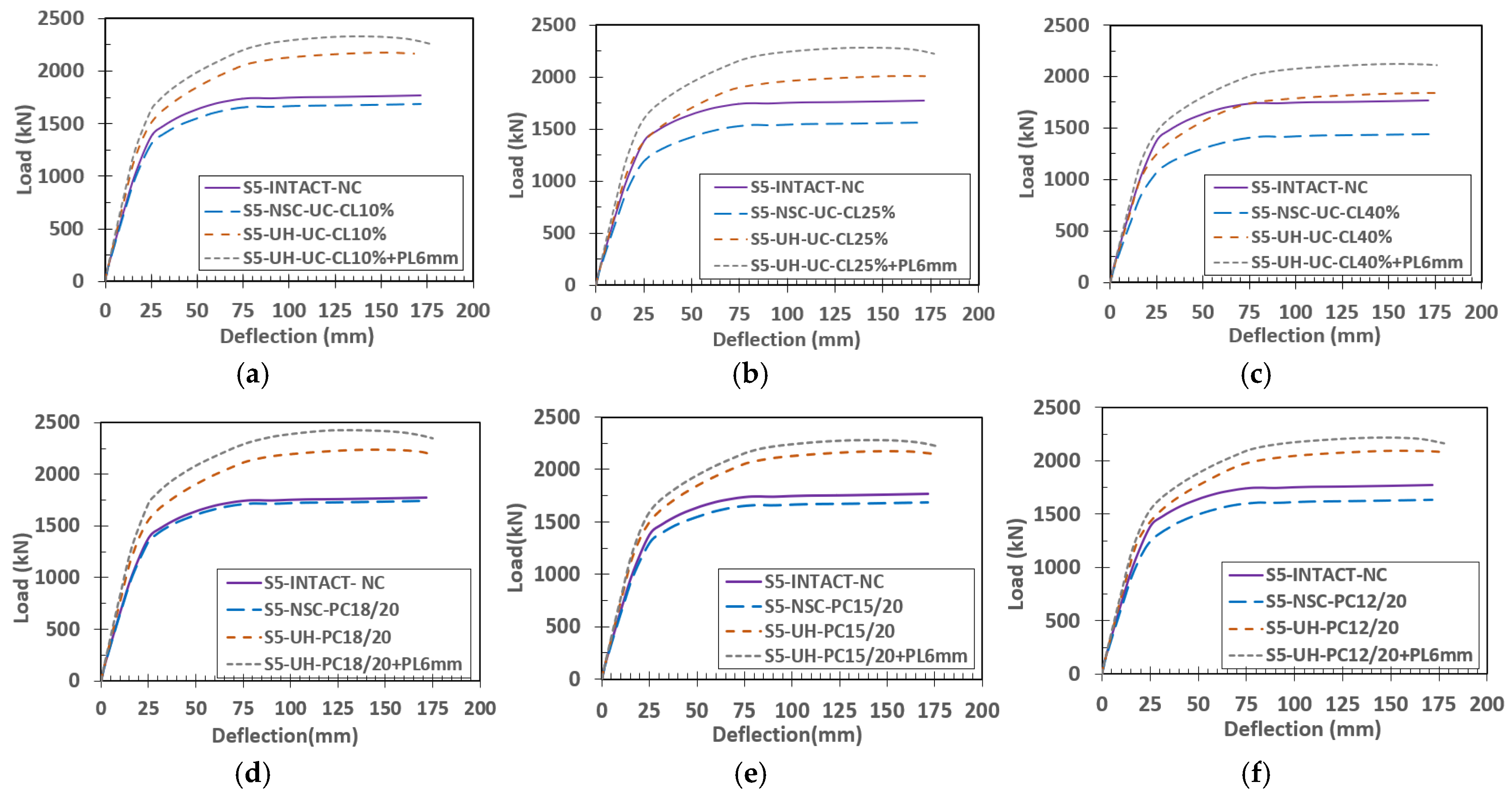
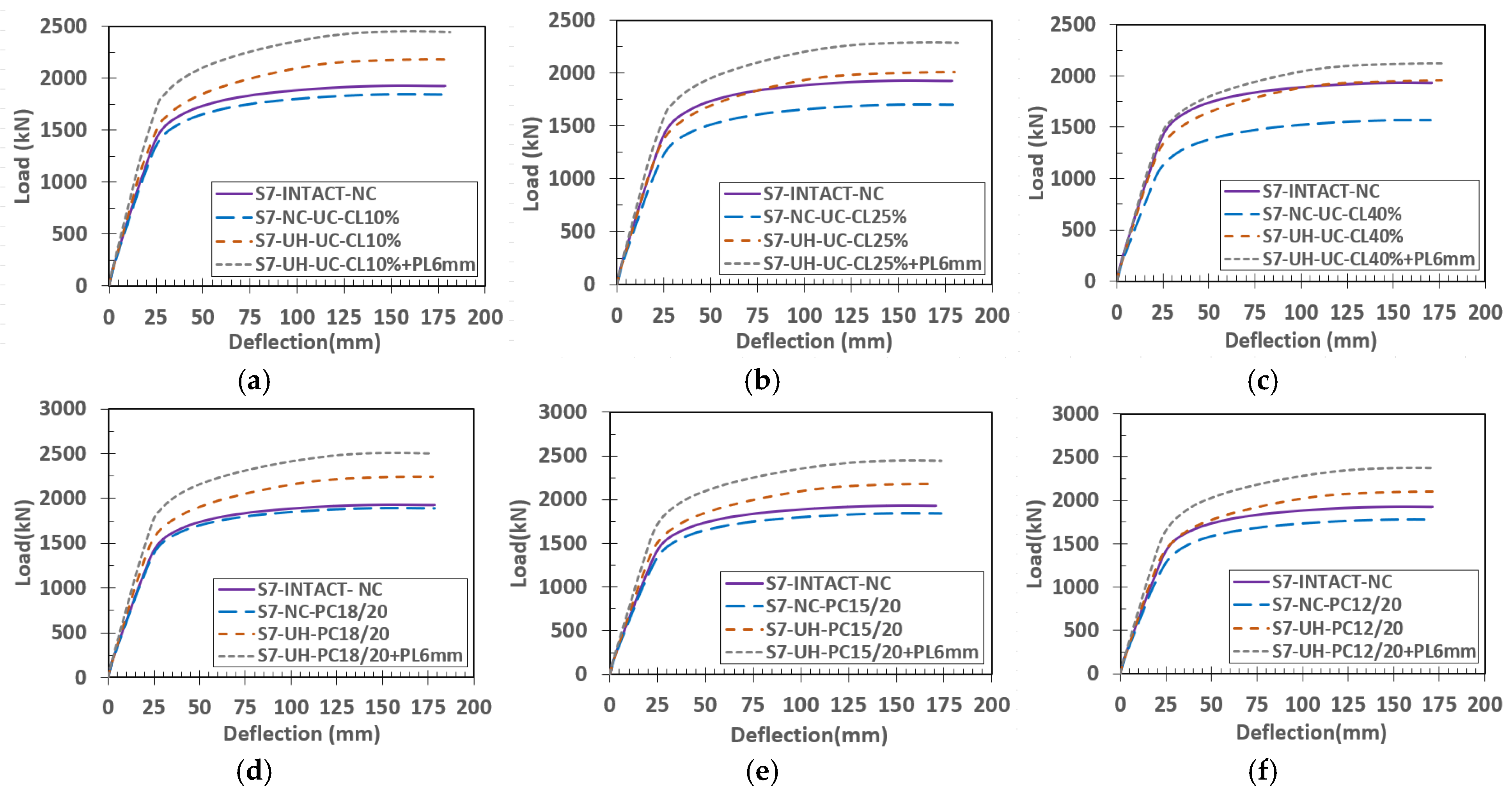
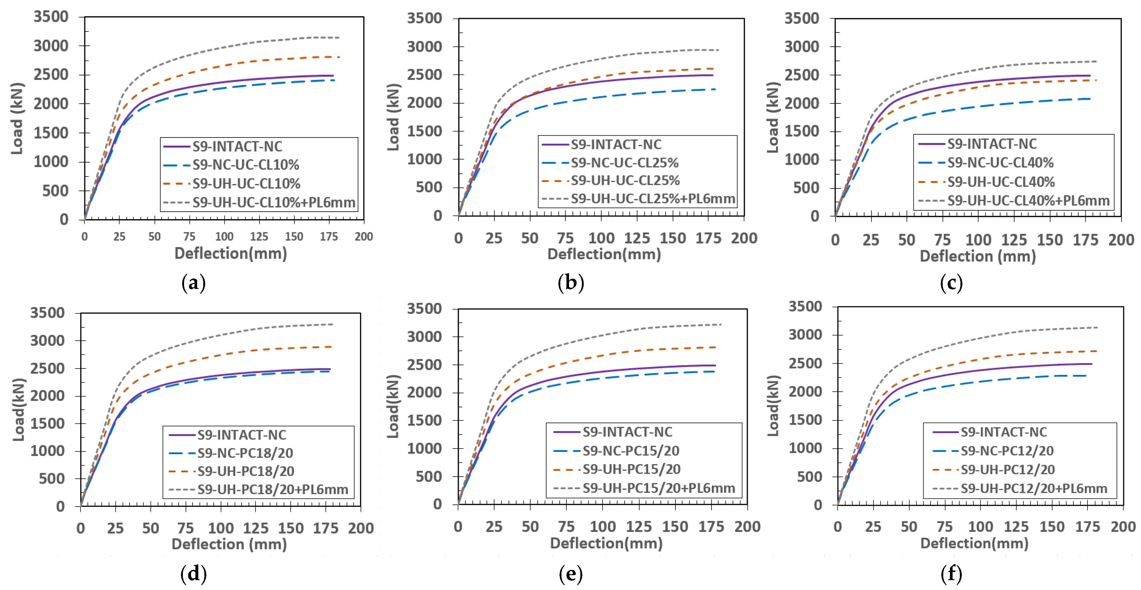
Figure 13,
Figure 14 and
Figure 15 present the load–midspan deflection responses for beams with spans of 5 m, 7 m, and 9 m, respectively. In each figure, subfigures (a), (b), and (c) correspond to uniform corrosion (UC) levels of 10%, 25%, and 40%, respectively. Within each subfigure, four cases are compared: the intact beam with NSC (intact-NC), the corroded NSC beam (NSC–corrosion level), the rehabilitated beam using a UHPC slab (UH–corrosion level), and the rehabilitated beam using UHPC combined with 6 mm thick welded steel plates (UH–corrosion level + PL6mm). Similarly, subfigures (d), (e), and (f) represent pit depth as a reduction relative to the intact thickness (e.g., 18/20 indicates a pit depth of 2 mm), representing a reduction in pit thickness of 10%, 25%, and 40%.
The results of the finite element analyses are evaluated in terms of load–deflection behavior. For all specimens, the failure mode is consistent and characterized by yielding of the steel beam at the lower flange, followed by crushing of the concrete slab. For each span, corrosion type, and corrosion level, the response of the intact NSC beam is used as a reference and compared with the corresponding corroded and rehabilitated configurations. The results clearly show that corrosion reduces the load-carrying capacity significantly for both uniform and pitting corrosion cases. Independent evaluations of the two corrosion types, based on their respective geometrical degradation parameters (percentage thickness loss for uniform corrosion and maximum pit depth for pitting corrosion), indicate that the degradation is more severe for the beams subjected to uniform corrosion. This behavior is due to the continuous reduction in the cross-sectional area along the entire critical region of the lower flange, resulting in a reduction in the overall flexural stiffness and global capacity. However, at this stage of the independent analysis, when pitting corrosion is controlled by the pit depth, it leads to a local distribution of the pits on the flange. This means that when considering the entire section, including both the corroded pits and the intact areas, the effective cross-section in the critical region of the beam undergoes a smaller volumetric reduction, and therefore, the overall capacity is reduced less severely than it would be for a completely uniform loss of thickness. However, a direct comparison with an equivalent mass loss scenario shows a different structural response.
The effect of corrosion level is also evident, with increasing corrosion from 10% to 40% leading to progressive reductions in strength. This trend is expected due to the corresponding loss in effective cross-sectional area. Nevertheless, the reduction in capacity for pitting corrosion remains comparatively moderate even at higher corrosion levels. This supports the previous discussion on the effect of corrosion type on strength reduction when the thickness loss due to pitting and uniform corrosion is the same.
The proposed rehabilitation method using UHPC slab replacement demonstrates significant effectiveness in restoring structural capacity. In most cases, the use of UHPC not only recovers the lost strength but also enhances the load-carrying capacity beyond that of the intact NSC beams (
Figure 13 in all cases). This improvement is attributed to the superior mechanical properties of UHPC, including higher strength and stiffness, as well as the reduction in dead load due to the thinner slab. The reduced self-weight contributes to improved overall structural performance, making this approach both efficient and practical. The enhancement is particularly notable for beams with low-to-moderate corrosion levels (10% and 25%) (
Figure 13a,b), where the proposed rehabilitation strategy is completely sufficient to fully recover the ultimate load-carrying capacity of the beam to its intact condition. Even for severe corrosion (40%), the UHPC rehabilitation method remains effective, restoring the capacity to levels comparable to or exceeding those of the intact beams. Further improvement is achieved when the UHPC slab replacement is combined with welded steel plate strengthening. This combined approach produces a synergistic effect, significantly increasing the flexural capacity across all beam spans, corrosion types, and corrosion levels. The steel plates enhance the load-carrying capacity of the corroded lower flange, while the UHPC slab improves global stiffness and strength. As a result, the combined method consistently provides the highest performance among all cases considered, as shown in
Figure 13 (all corrosion levels).
Figure 14 and
Figure 15 further illustrate the load–midspan deflection responses for beams with spans of 7 m and 9 m, respectively. The observed trends are consistent with those presented for the 5 m span beams in
Figure 13. In both figures, the introduction of corrosion leads to a clear reduction in load-carrying capacity, with uniform corrosion causing more pronounced degradation compared to pitting corrosion. Increasing the corrosion level from 10% to 40% results in a progressive decrease in beam capacity, which is evident across all cases. The effectiveness of the rehabilitation methods is also consistent with the findings from
Figure 13. The use of UHPC slab replacement successfully restores and, in many cases, enhances the load-carrying capacity compared to the corroded NSC beams, particularly for lower and moderate corrosion levels. For higher corrosion levels, the UHPC rehabilitation still provides substantial recovery in capacity, often approaching or exceeding that of the intact beams. The addition of welded steel plates further improves the performance, resulting in the highest load-carrying capacities among all configurations. These consistent trends across different spans confirm the reliability and robustness of the proposed rehabilitation approach.
3.2. Normalized Capacity vs. Corrosion Level
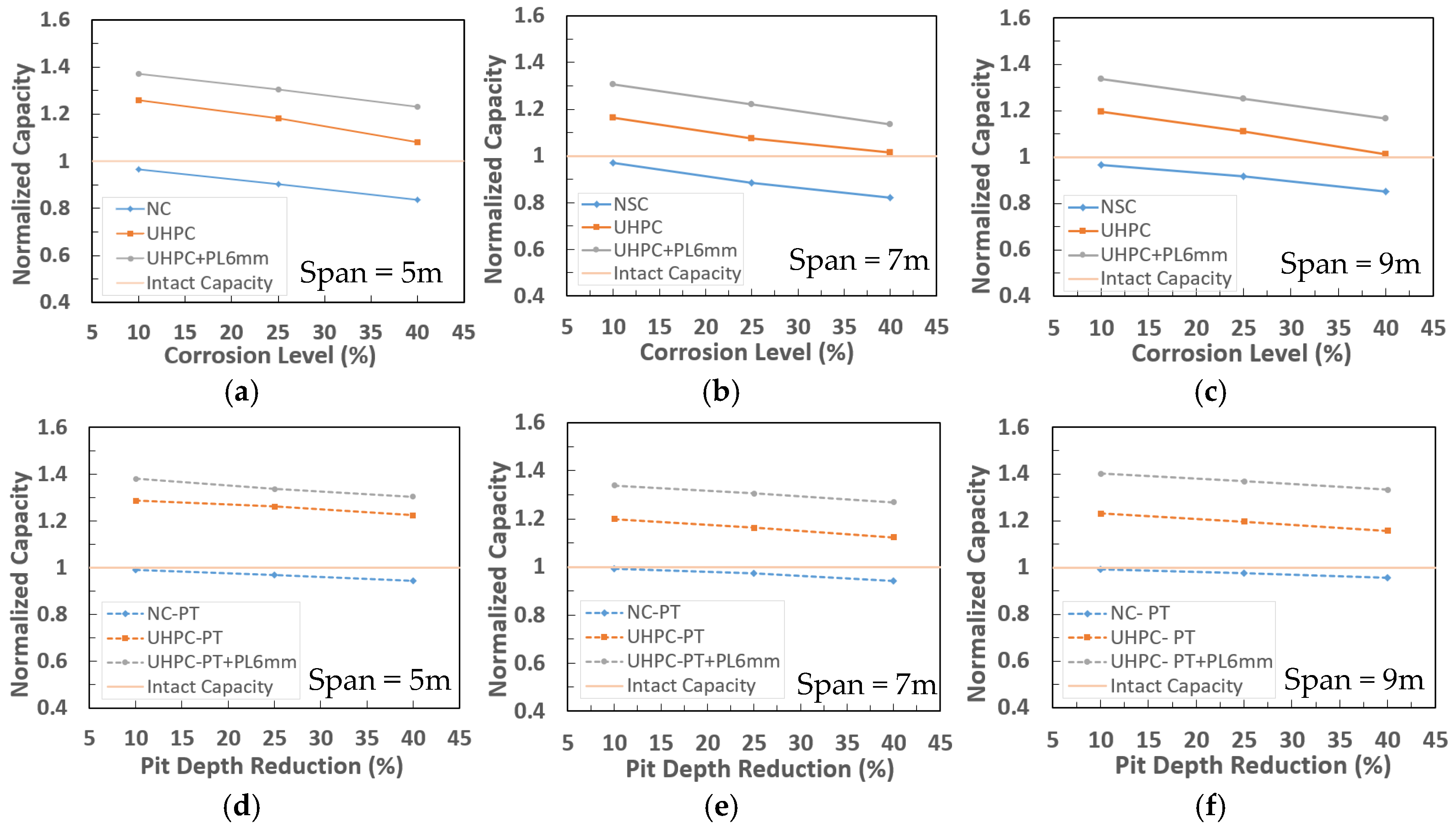
The effect of corrosion severity becomes more apparent when the results are normalized with respect to the intact beam capacity.
Figure 16 presents the variation in load-carrying capacity, showing both the degradation in corroded beams and the enhancement achieved through rehabilitation using UHPC alone or UHPC combined with steel plates. In this figure, a capacity ratio of 1.0 represents the intact beam without corrosion. Solid lines correspond to uniform corrosion, while dashed lines represent pitting corrosion. It can be observed that, regardless of beam span, there is an approximately linear reduction in capacity with increasing corrosion severity for both corrosion types. However, the rate of reduction is higher for uniform corrosion in all cases. This behavior is attributed to the continuous loss of material in the critical region at midspan for uniform corrosion, whereas pitting corrosion results in localized damage with an accumulation of weight loss that does not reduce the effective cross-sectional area to the same extent.
For all studied beams, the proposed rehabilitation methods are highly effective. The use of UHPC alone is sufficient to restore the load-carrying capacity to values equal to or greater than that of the intact beams, even at higher corrosion levels. The combined use of UHPC and welded steel plates further enhances the capacity, reaching values of approximately 1.4 for 5 m span beams at 2 mm pit reduction (18/20), as shown in
Figure 16d. Even at a severe uniform corrosion level of 40%, the UHPC-only rehabilitation method increases the capacity beyond unity, as illustrated in
Figure 16c, demonstrating the robustness of the proposed approach. Despite these findings, the relatively lower degradation observed in pitting corrosion cases requires further investigation and is discussed in the next section.
3.3. Pitting Corrosion vs. Uniform Corrosion at the Same Weight Loss
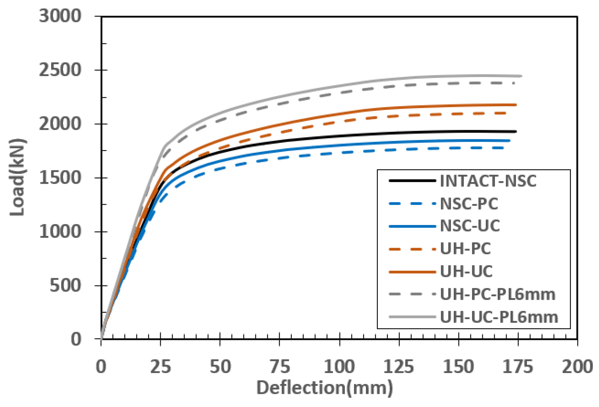
To further investigate the observation that pitting corrosion resulted in lower degradation than uniform corrosion, an additional set of finite element simulations was conducted. In this analysis, beams with a span of 7 m were modeled such that both corrosion types exhibited the same mass loss.
Figure 17 presents the load–deflection responses, where the intact beam is shown with a solid black line, uniform corrosion is represented by solid colored lines, and pitting corrosion is indicated by dashed lines. The results show that, when the mass loss is kept identical for both corrosion types, beams with pitting corrosion exhibit a lower load-carrying capacity compared to those with uniform corrosion. This behavior is attributed to the presence of stress concentrations caused by localized pits, which accelerate the initiation of yielding and reduce the effective strength of the section. This finding confirms that the previously observed lower degradation in pitting corrosion cases was primarily due to the smaller equivalent mass loss within the critical region, rather than an inherent advantage of pitting corrosion.
Overall, for both types of corrosion, the proposed rehabilitation methods proved to be highly effective. The use of UHPC slab replacement significantly increased the load-carrying capacity of the corroded beams, often exceeding that of the intact beams. Further enhancement was achieved by incorporating welded steel plates, which provided additional strength to the corroded lower flange. Given the strong performance of these rehabilitation strategies, their applicability is further explored through a practical case study presented in the next section.




 ,
,