Article

Evaluation of Compressive Behavior of Hoop Filament Wound Components: Comparison Between CFRP and BFRP Composites


Department of Industrial Engineering and Mathematical Science, Università Politecnica Delle Marche, Via Brecce Bianche 12, 60131 Ancona, Italy
*
Author to whom correspondence should be addressed.
J. Compos. Sci. 2026, 10(6), 291; https://doi.org/10.3390/jcs10060291
Submission received: 14 April 2026 / Revised: 13 May 2026 / Accepted: 24 May 2026 / Published: 27 May 2026

Abstract

Fiber-reinforced polymer composites are widely used in industrial applications due to their high specific mechanical performance. In particular, carbon fiber-reinforced polymers (CFRPs) are most commonly used for automotive and aerospace sectors, but their production is energy-intensive and associated with relevant environmental impacts. Therefore, the interest in natural fibers is growing. Among them, basalt fibers are used as reinforcement of polymer matrix composites since the basalt fiber-reinforced polymers (BFRPs) exhibit good mechanical properties combined with a low ecological footprint. In this context, the present study provides a comparative experimental evaluation of CFRP and BFRP tubular components realized by means of a hoop filament winding process (winding angle equal to 88°). Radial and axial compression tests were performed according to ASTM D2412 and ASTM D695 standards to assess pipe stiffness, maximum compressive stress, and failure mechanisms. It was demonstrated that the fiber type strongly influences compressive behavior and damage mechanisms. Furthermore, the main results show that CFRP components are characterized by the highest pipe stiffness, approximately equal to 8.9 MPa with respect to 6.0 MPa of BFRP ones, while BFRP samples demonstrate a more elastic and progressive deformation behavior under radial loading. Both materials exhibit similar peak stress values under axial compression tests, equal to about 60 MPa, due to the load direction, which is perpendicular to the fiber orientation; thus, the mechanical properties are assimilable to those of the matrix.

1. Introduction

Over the last few decades, fiber-reinforced polymer (FRP) composites have progressively established themselves as a cornerstone class of materials in high-performance engineering applications, such as in aerospace, automotive, civil, and energy fields. Their widespread adoption is primarily driven by an outstanding combination of high specific stiffness and strength, excellent corrosion resistance, and low density, which enables the design of lightweight yet structurally efficient components [1,2]. The possibility of tailoring mechanical performance through fiber selection, orientation, stacking sequence, and matrix formulation further enhances their versatility, making FRPs particularly suitable for applications in which durability, high mechanical properties, and mass reduction are crucial design requirements.
Among the different FRP systems, carbon fiber-reinforced polymers (CFRPs) are widely considered as the benchmark for high-performance structural applications. As a matter of fact, CFRPs exhibit high tensile strength, elastic modulus, and fatigue resistance, enabling their widespread application in aircraft primary structures, high-performance automotive components, wind turbine blades, and pressure vessels [3,4,5]. Their excellent strength-to-weight ratio enables significant reductions in structural mass without compromising mechanical integrity. However, the production of carbon fibers, typically derived from polyacrylonitrile (PAN) precursors through stabilization and high-temperature carbonization, is highly energy-intensive and associated with considerable CO2 emissions and high manufacturing costs [3]. Such drawbacks have stimulated increasing research efforts toward identifying sustainable alternatives capable of achieving comparable mechanical performance with a reduced environmental footprint [6,7,8].
In this framework, basalt fiber-reinforced polymers (BFRPs) have emerged as a promising and more sustainable alternative to CFRPs. Basalt fibers are obtained from naturally occurring volcanic rocks through a simple melting and extrusion process, which is less energy demanding and environmentally harmful than carbon fiber production [9].
Recent investigations have shown that BFRPs combine good tensile strength, chemical stability, thermal resistance, durability in aggressive environments, and low environmental impact, making them particularly suitable for sustainable engineering applications [9,10,11]. Furthermore, as shown by Özbek et al. (2024) and Sun et al. (2024), BFRPs are characterized by mechanical stability under harsh environmental conditions, including high temperature, elevated pressure, and corrosive atmosphere, outperforming many conventional composites in long-term durability [6,7].
Although BFRPs generally exhibit slightly lower mechanical performances than CFRPs, they offer higher cost-effectiveness and environmental advantages, providing a balanced compromise between performance and sustainability. Comparative analyses have shown that, although CFRPs exhibit superior axial strength and stiffness, BFRPs offer improved impact resistance and greater energy absorption capacity, making them particularly suitable for crashworthiness applications [12,13,14,15,16,17].
As far as the advanced manufacturing techniques for the realization of FRP structures are concerned, the filament winding (FW) process has become the most established technique for producing high-precision tubular components and pressure vessels [13,18]. The process involves winding continuous fibers, pre-impregnated with a polymer matrix, around a rotating mandrel according to predefined trajectories. After curing, the mandrel is removed, leaving a hollow composite structure with a well-defined geometry and fiber architecture. A key design parameter in filament-wound tubes is the winding angle, defined as the angle between the fiber direction and the longitudinal axis of the tube. This parameter has a significant effect on stiffness, strength, load transfer mechanisms, and failure modes [19,20,21,22,23].
Experimental studies available in scientific literature have demonstrated that the mechanical performances of wound tubular components in FRP composites are strongly affected by the winding configuration. Specifically, winding angles of ±40–45°, which lead to fibers more aligned with the tube axis, generally maximize axial compressive strength and specific energy absorption. For instance, Özbek (2019) investigated the influence of fiber orientation angles on the crashworthiness of CFRP pipes subjected to axial compression [24]. They demonstrated that CFRP tubes wound at ±40°, characterized by the lowest fiber orientation angles investigated, exhibited the highest total energy absorption, mean crushing stress, and specific energy absorption. Similarly, Quanjin et al. (2020) showed that, as the winding angle increases, compressive modulus, energy absorption, and specific energy absorption decrease [20]. Conversely, high winding angles of ±70°–75°, leading to fibers oriented closer to the hoop configuration, enhance circumferential stiffness and radial load-bearing capacity. Zhang et al. (2025) found that high winding angle values significantly increase load-carrying capacity; in particular, they observed that increasing the winding angle from ±35° to ±75° tubular components increases strength by 123.5% compared to the ±35° ones, demonstrating the significant dependence of compressive performance on winding geometry [19]. The mechanical response and failure modes of filament-wound tubes are also highly sensitive to the loading orientation. Under axial compression, failures are typically characterized by brittle fracture, lamina bending, and local buckling. On the contrary, lateral or radial compression tends to induce matrix cracking, delamination, and fiber breakage [16,17,25]. Such failure mechanisms are strongly affected by fiber type and laminate architecture. For example, CFRP tubes often fail catastrophically due to the brittle nature of carbon fibers, whereas BFRP tubes usually exhibit more progressive damage evolution, resulting in enhanced energy absorption and impact resistance [24].
To enhance the mechanical performance of components, many authors have investigated hybridization strategies, by combining different fibers such as basalt, glass, and carbon ones in intraply or interply configurations. Levi et al. (1995), Cui et al. (2020), and de Menezes et al. (2023) demonstrated that the introduction of three-directional lay-ups or hybrid plies significantly enhances compressive strength and energy absorption, often by 30–100%, as compared to traditional angle-ply laminates [22,23,26]. Furthermore, hybrid structures tend to delay catastrophic failure and promote more stable load-displacement responses through synergistic load-sharing mechanisms among different fiber types. Moreover, Kessler et al. (2015,2016) showed that the incorporation of hoop-oriented layers in multi-axial configurations can increase ultimate compressive strength while improving tolerance to buckling and delamination [27,28]. These findings underline the key role of fiber architecture and material selection in tailoring the mechanical performance of filament-wound composite tubular parts for specific loading scenarios.
Although the mechanical behavior and failure mechanisms of filament-wound FRP tubular structures have been investigated in scientific literature, most available studies are focused on a single composite system, specific loading conditions, or crashworthiness-oriented applications [16,17,20,24,25]. Specifically, CFRP tubular components have been investigated because of their high stiffness and energy absorption capability, whereas investigations on BFRP systems are still comparatively limited and mainly focused on durability, impact resistance, or hybrid configurations [6,7,15,16].
Furthermore, only a few studies provide a direct comparison between CFRP and BFRP tubular components realized under the same filament winding conditions and tested under different compressive loading configurations. In addition, the correlation between the global mechanical response and the associated failure mechanisms under both radial and axial compression loading has not yet been sufficiently clarified, especially for high winding angles close to the hoop configuration. Given the increasing demand for sustainable and lightweight structural materials, such a comparison is particularly relevant. Basalt fibers represent a promising lower-environmental-impact alternative to conventional carbon fibers due to their less energy-intensive production process and lower associated environmental footprint [3,6,7,8,9,10]. However, further experimental investigations are still required to better assess their structural response and failure behavior in filament-wound tubular structures subjected to compressive loading conditions.
In this framework, the present study aims to provide a comparative experimental investigation of hoop filament-wound CFRP and BFRP tubular components manufactured with the same winding parameters and tested under both radial and axial compression conditions. In addition to the conventional compressive properties, the analysis includes the evaluation of energy absorption capability, circumferential bending stress, maximum load per unit length, and circumferential elastic modulus to provide a more comprehensive characterization of the structural performance of the investigated tubular parts. Attention is also focused on the relationship between compressive response, stiffness evolution, and damage mechanisms through stereomicroscopic analysis of the fractured specimens.

2. Materials and Methods

2.1. Materials

Composite tubular specimens were produced using basalt and carbon fiber towpregs. The unidirectional tows were impregnated with epoxy resin through an automated manufacturing process [29]. A Huntsman International LLC (Tienen, Belgium) epoxy resin, characterized by a gel temperature (Tgel) of 90 °C and a glass transition temperature (Tg) of 120 °C, was used to impregnate both carbon and basalt fibers. To prevent degradation of the resin or premature curing, the towpregs spools were stored in an industrial refrigerator at −18 °C.
The Basaltex 1200 (Wevelgem, Belgium) was used as reinforcement of basalt tows, characterized by a width equal to 6 mm. The BF towpreg resulted in a resin weight fraction (wm%) equal to 28.2%. As far as the carbon fiber towpregs are concerned, TRH 50 Mitsubishi 30K (Tokyo, Japan) CF filaments, with a width equal to 10 mm, were used. The CF towpreg resulted in a resin weight fraction equal to 28.2%. By assuming zero void content of the towpregs, the fiber content for both CFRP and BFRP is equal to 71.8%.

2.2. Filament Winding and Curing Processes

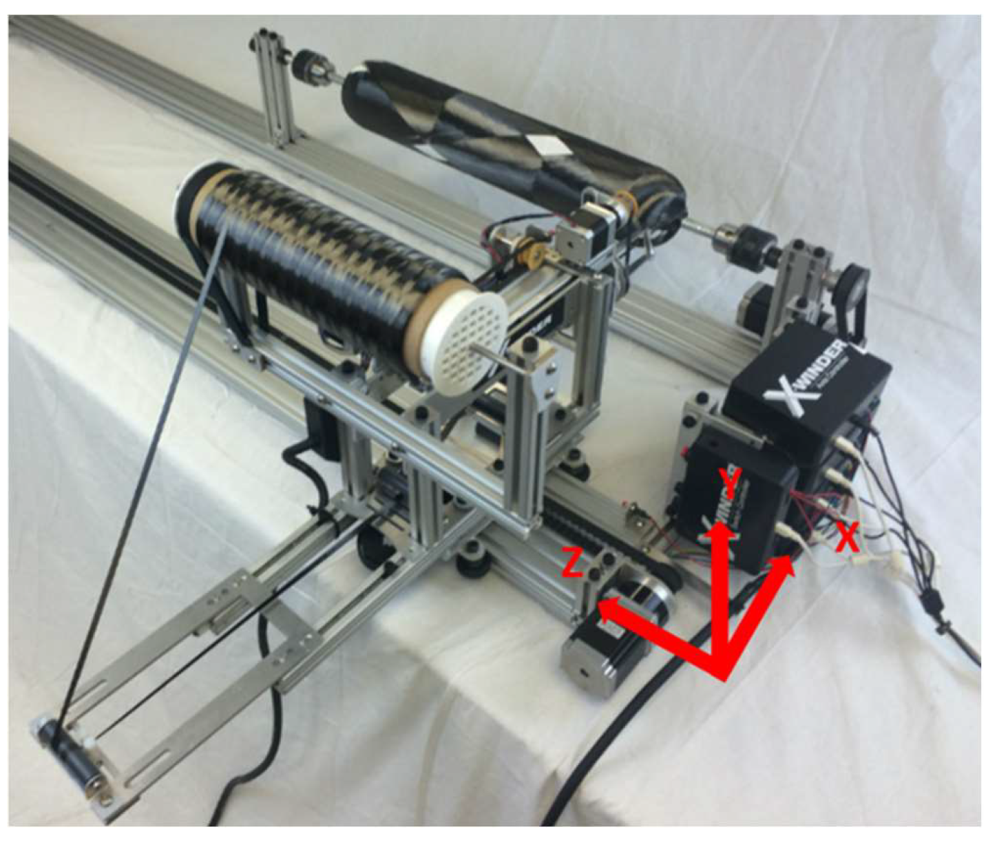
The tubular components in CFRP and BFRP were manufactured using X-Winder (Cincinati, OH, USA), the laboratory-scale filament winding machine shown in Figure 1. The system is equipped with four controlled axes: the X-axis moves the cross carriage toward the rotating mandrel, the Z-axis enables the carriage to travel along the mandrel’s longitudinal direction, the W-axis provides mandrel rotation around the Z-axis, and the U-axis allows the deposition head to rotate around the X-axis. These coordinated movements enable precise fiber winding around the mandrel. Specifically, the X-axis is used to cover the vessel domes, the Z and U axes control the winding along the cylindrical section, and the W-axis manages mandrel rotation. The final fiber deposition pattern and angle result from the combination of the translation of the deposition head and the rotation of the mandrel.
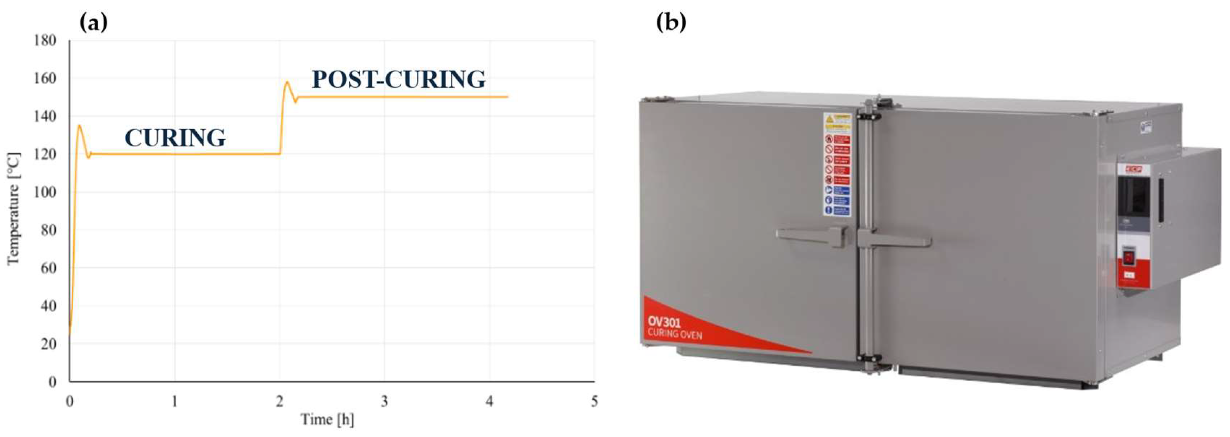
Tubular components characterized by an inner diameter equal to 35 mm were realized with two layers with a winding angle equal to 88° and subsequently cured with a dedicated composite oven (OV301 Curing Oven, EasyComposites, Rijen, The Netherlands). According to the resin manufacturer’s recommendations, the parts were cured at 120 °C for 2 h, followed by a second stage at 150 °C for 2 h, and then allowed to cool in air. Figure 2 shows the applied curing cycle and the oven used for the curing process.
The cured tubes were subsequently cut to obtain tubular specimens for the evaluation and comparison of the mechanical properties of the two investigated materials.
Table 1 summarizes the geometrical, mass, and processing parameters of the manufactured specimens. For each material system (CFRP and BFRP), four specimens were tested under radial compression, while three specimens were subjected to axial compression tests. The specimens nomenclature adopted in this study is also reported in Table 1 and is defined as follows: the first term identifies the composite material (CFRP or BFRP), the second term indicates the winding angle (in this research, 88°), the third term specifies the test configuration (RC for radial compression and AC for axial compression), whereas the final number identifies the specimen within the same test series.

2.3. Compression Tests

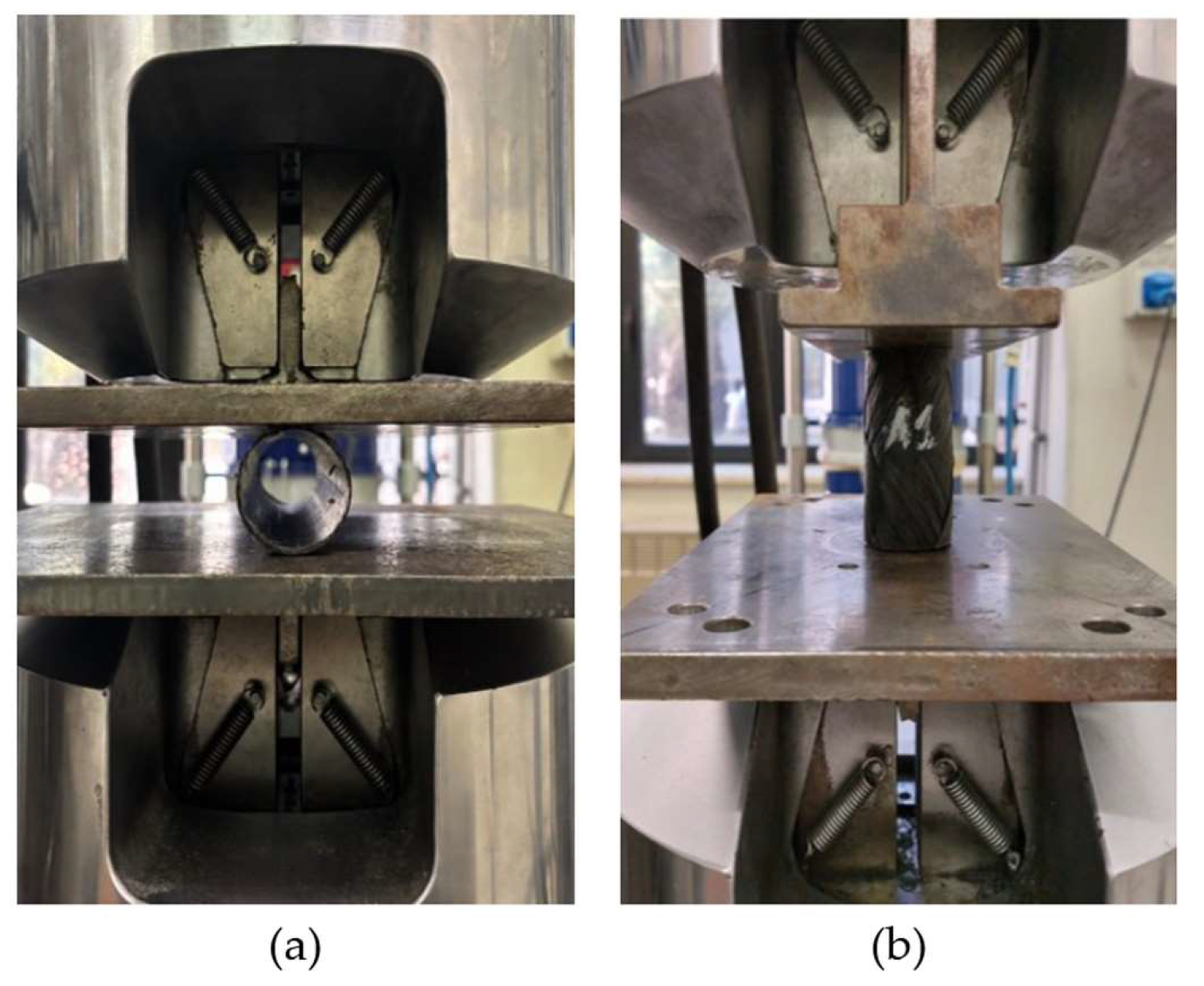
In order to characterize the compressive behavior of the wound components in BFRP and CFRP composite materials, radial and axial compression tests were performed using the universal testing machine MTS 810® (MTS Systems Corporation, Eden Prairie, MN, USA) equipped with a 250 kN load cell, at room temperature, under a constant crosshead displacement rate of 12.5 ± 0.5 mm/min. The compressive load was applied through two flat, smooth plates in tool steel, whose dimensions exceeded the specimen length, ensuring uniform contact during testing (Figure 3).
As far as the radial compression test is concerned (Figure 3a), specimens were realized and tested according to ASTM D2412 [30]. The specimens, characterized by an internal diameter of 35 mm and a length of 300 mm, were obtained through cutting operations. First, the external turned region generated during the filament winding process was removed to ensure uniform geometry and surface quality. Subsequently, equidistant cuts of 250 mm were performed along the tube length to obtain specimens with the required dimensions.
According to the ASTM D2412 [30] standard, the pipe stiffness (PS) was evaluated using the force–displacement data acquired during the tests. In particular, the standard recommends stopping the test when the vertical displacement reaches 30% of the internal diameter. The standard defines a key parameter to calculate PS, namely the deflection Δy. This parameter represents the variation in percentage of the internal diameter, expressed in millimeters. According to the standard, the pipe stiffness must be determined at a specified deflection level, typically corresponding to 5% or 10% of the internal diameter. The pipe stiffness, calculated according to Equation (1), is a function of the applied load (F), the corresponding deflection Δy (5% or 10%), and the specimen length (l):
P S = F y · l
As far as the axial compression test is concerned (Figure 3b), the ASTM D695 [31] standard was followed. Three tubular specimens, realized by filament winding process with an inner diameter of 35 mm and a height of 70 mm [16], were cut at both extremities to remove the irregular thickness of the turning zones obtained during the FW process. During axial compression tests, load and displacement were acquired in order to plot results in terms of load vs. displacement curves and then derive the compressive behavior of the parts.
In addition to the standard parameters obtained from radial compression tests according to ASTM D2412 [30], a set of derived mechanical properties was calculated in order to enable a more comprehensive comparison between CFRP and BFRP tubular specimens. The maximum load per unit length (qmax) was determined by normalizing the peak load recorded during the radial compression test ( F max ) with respect to the length of the tubular component (l), as shown in Equation (2). This parameter provides a direct measure of the load-bearing capacity of the tubular structure under radial compression.
q max = F max l
The circumferential bending stress (σθ,bending) was also evaluated from the maximum load condition by considering the tubular geometry and the loading configuration defined by the parallel-plate test (Equation (3)). This parameter represents the stress state associated with bending-dominated deformation induced by ovalization of the tube cross-section:
σ θ , bending = 3 · C · F max · ( D i + t ) l · t 2
in which C is a friction dependent coefficient, and Di and t are, respectively, the internal diameter and thickness of the tubular component [32,33].
The specific bending stress was calculated by normalizing σθ,bending with respect to the specimen mass, to account for differences in material density and enable a weight-efficient comparison between CFRP and BFRP composites.
The total energy absorption was evaluated as the area under the load–displacement curve up to the maximum displacement considered in the test. This parameter quantifies the ability of the material to dissipate energy during deformation and damage evolution. The specific energy absorption was then calculated by dividing the absorbed energy by the specimen mass, providing an indicator of energy absorption efficiency per unit weight.
Finally, the circumferential elastic modulus (Eθθ) was evaluated according to [34,35] from the initial linear portion of the load–displacement curve, where the material exhibits an elastic response (Equation (4)). This parameter reflects the stiffness of the tubular structure under radial loading:
E θ θ = k · 0.0186 · D m e a n I
in which K is the stiffness of the tubular component retrieved from load-displacement curves, Dmean is the mean diameter, and I is the inertia moment of the cross-section.

2.4. Fracture Analysis by Means of the Stereomicroscopy

After radial and axial compression tests were carried out, the fractured surfaces of the specimens were observed using a stereomicroscope (Leica M205 C, Leica Microsystems, Wetzlar, Germany). The observations were performed to identify the main failure mechanisms developed during the compressive loading. Particular attention was devoted to features such as fiber breakage, matrix cracking, delamination, and possible fiber–matrix debonding. The stereomicroscopic analysis also allowed a qualitative comparison of the fracture morphology of the CFRP and BFRP specimens, providing results on the effect of the reinforcement type on the failure behavior of the tubular parts.

3. Results

3.1. Radial Compression Test Results

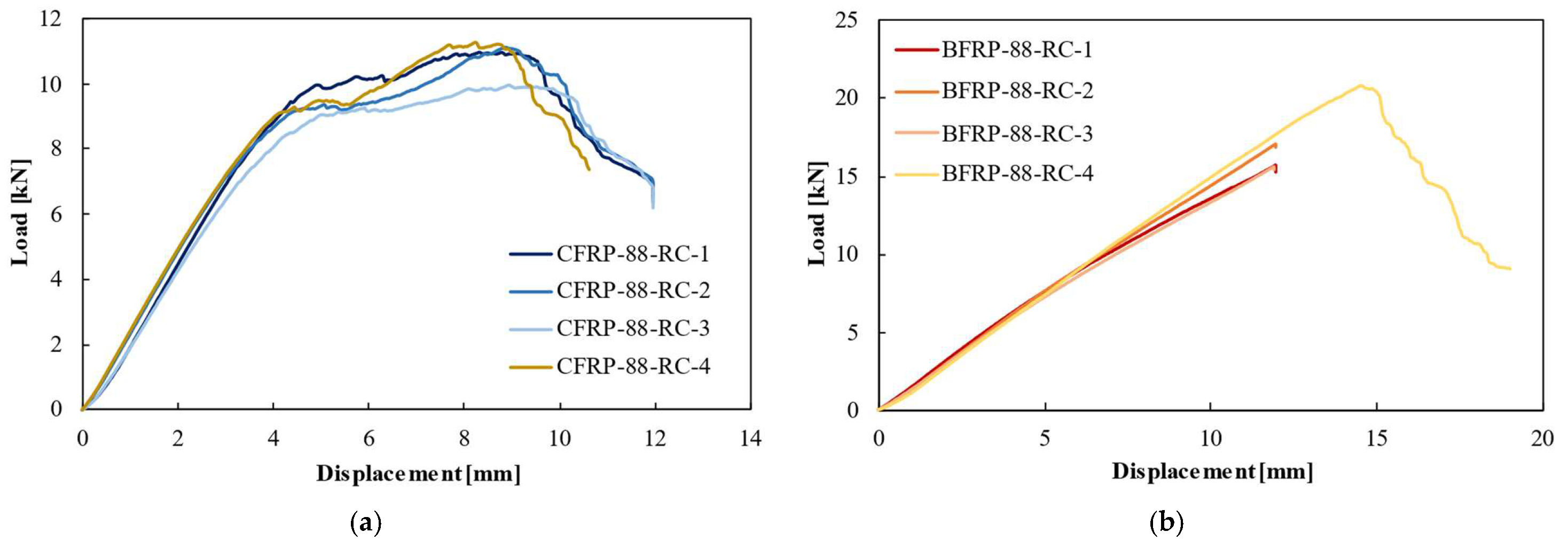
Figure 4a shows the typical load vs. displacement curves obtained by CFRP tubular specimens subjected to radial compression tests. As the displacement rises, the applied load progressively increases until a peak value corresponding to the onset of fracture. Such behavior can be attributed to the elastic deformation of the composite hoop wound specimens, in which both the fibers and the polymer matrix contribute to the structural stiffness of the component. During this phase, the tubular geometry gradually ovalizes under the compressive load applied by the parallel plates, leading to an increase in the contact area and consequently in the measured load. At the maximum load recorded during the test, localized damage mechanisms, such as matrix cracking, fiber–matrix debonding, and the initiation of delamination between adjacent plies, begin to develop within the composite structure. These damage phenomena reduce the load-carrying capability of the composite material, leading to the onset of fracture. Beyond the peak value, the load decreases as the displacement further increases due to the propagation of damage within the composite structure and the progressive collapse of the tubular section, which results in a reduction in structural stiffness.
A good level of repeatability was observed, as shown by the close agreement among the load–displacement curves obtained from different specimens tested under the same conditions. According to the international standard adopted, tests were interrupted when the displacement reached a value corresponding to approximately 30% of the internal diameter. The peak load associated with the onset of fracture occurs generally at a displacement value of about 9–9.5 mm.
Figure 4b shows the typical load vs. displacement curves obtained by the radial compression tests performed on BFRP specimens, according to the adopted standard ASTM D2412. It can be observed that the load rises with displacement. However, when the test is interrupted at a displacement corresponding to approximately 30% of the internal diameter as prescribed by the standard, the maximum load is not reached. In order to fully characterize the compressive behavior of the BFRP wound tubular specimens, additional radial compression tests were carried out until specimen failure. The results show that BFRP specimens exhibit a peak load of about 20 kN, associated with a displacement of about 14.5 mm, which is higher than that observed for the CFRP specimens.
This different behavior can be partly attributed to the higher mass of the BFRP specimens, resulting from the higher density of basalt fibers as compared with carbon fibers. Furthermore, the different mechanical responses of CFRP and BFRP composite materials can also be related to the intrinsic mechanical characteristics of the fibers. Basalt fibers generally are characterized by both higher strain to failure and energy absorption capability than carbon fibers [17], leading to the higher displacement observed at peak load. Another relevant discrepancy between CFRP and BFRP materials concerns their overall mechanical response under radial compression. The BFRP specimens exhibited a predominantly quasi-elastic behavior in a wider displacement range, characterized by a more gradual stiffness reduction before failure. On the contrary, CFRP specimens show a more brittle behavior, with earlier damage initiation and a more pronounced drop in load once the peak value is reached.
Based on the load vs. displacement curves, the pipe stiffness and specific pipe stiffness of each specimen were calculated according to Equation (1), considering both the deflection values (Δy) of 5% and 10% of the specimen’s inner diameter. Table 2 summarizes the length of each specimen, pipe stiffness, specific pipe stiffness, and their mean values.
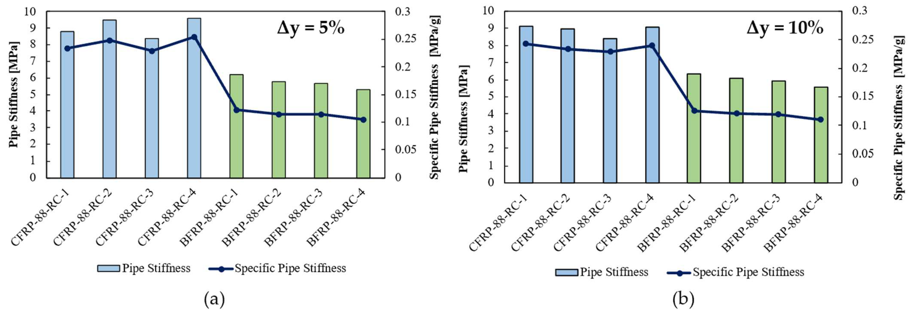
Figure 5 shows the comparison between CFRP and BFRP materials in terms of pipe stiffness and specific pipe stiffness obtained by radial compression tests at Δy = 5% (Figure 5a) and at Δy = 10% (Figure 5b). It can be observed that the CFRP specimens, represented by the blue columns, reached higher values of PS than those obtained by the BFRP specimens, shown by the green columns. Specifically, the medium value of PS of CFRP specimens is about 8.88 MPa, while the one related to BFRP ones is about 5.98 MPa. These values of PS calculated by considering a deflection value equal to 10% of the diameter are similar to those calculated based on a deflection of 5%, respectively equal to 9.07 MPa and 5.74 MPa. These results demonstrate that regardless of the deflection value considered, the resulting PS values are similar. Moreover, the specific PS of CFRP specimens is higher than that of BFRP specimens; the mean values are equal to 0.24 MPa/g and 0.12 MPa/g, respectively, for CFRP and BFRP.
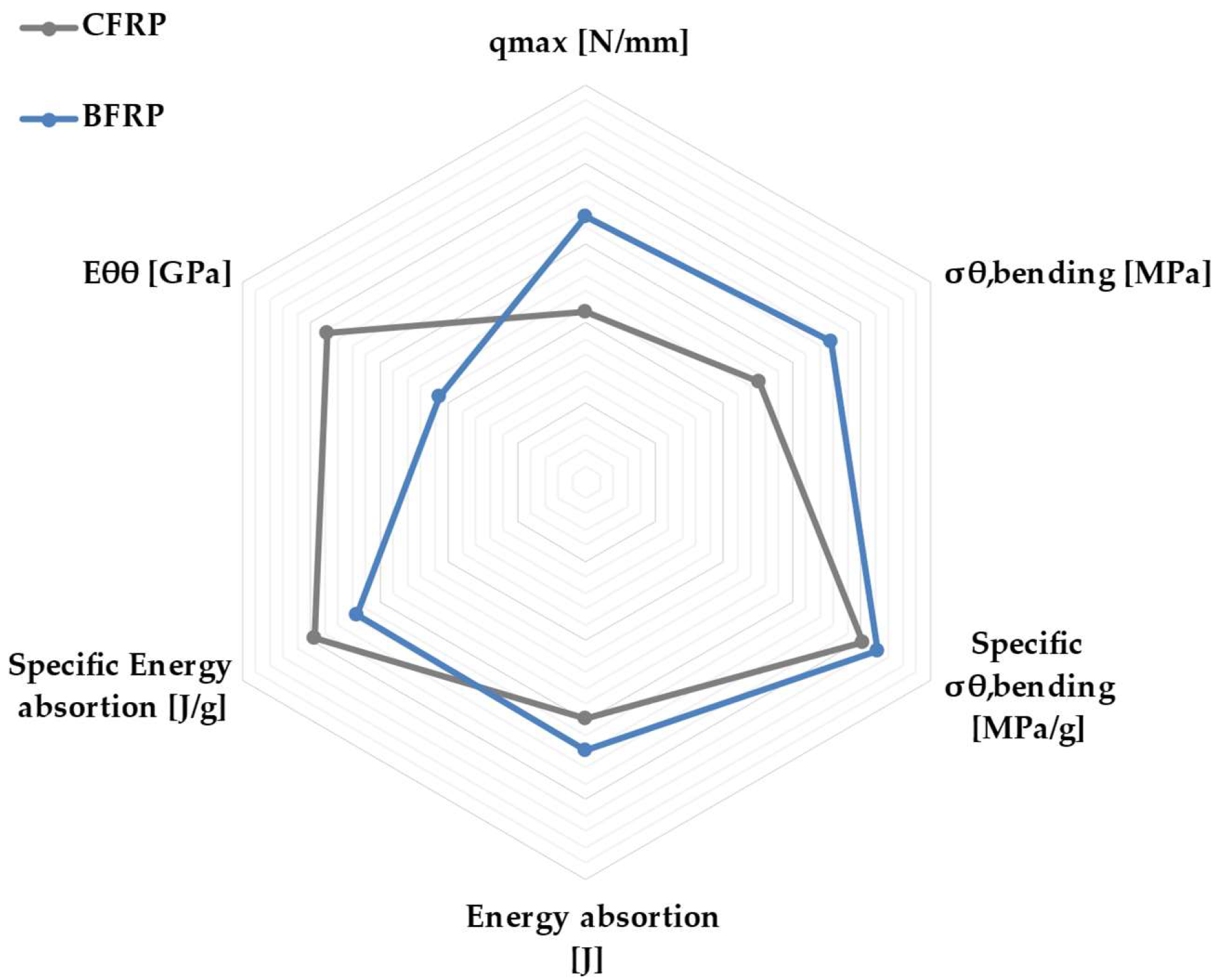
To provide a more comprehensive comparison of the mechanical performance of CFRP and BFRP tubular specimens under radial compression, a statistical analysis of the main parameters was carried out. The mean values and corresponding standard deviations of the investigated properties are summarized in Table 3 and graphically represented in Figure 6. The results show that BFRP specimens exhibit a significantly higher maximum load per unit length (qmax), with an average value of 66.78 N/mm compared to 42.91 N/mm for CFRP. The corresponding standard deviations are relatively low (5.36% for BFRP and 4.08% for CFRP), indicating a good repeatability of the experimental results. A similar trend is observed for the circumferential bending strength (σθ,bending), where BFRP reaches an average value of 1065.84 MPa, significantly higher than that of CFRP (756.51 MPa). The dispersion of the data remains limited for both materials, with standard deviation values of 5.85% and 5.22%, respectively. When considering the specific bending strength, the difference between the two materials is less pronounced. BFRP exhibits a slightly higher mean value (21.16 MPa/g) compared to CFRP (20.12 MPa/g), with standard deviations of 5.69% and 4.06%, respectively. This result suggests that the higher absolute strength of BFRP is partially balanced by its higher density. In terms of energy absorption, BFRP specimens show a higher average value (101.10 J) than CFRP (89.17 J), confirming their enhanced capability to dissipate energy under compressive loading. Moreover, BFRP exhibits a lower standard deviation (2.66%) compared to CFRP (4.50%), indicating a more stable and repeatable energy absorption behavior. On the contrary, CFRP outperforms BFRP when considering the specific energy absorption, with mean values of 2.37 J/g and 2.01 J/g, respectively. The relatively low standard deviations (4.22% for CFRP and 2.40% for BFRP) confirm the consistency of these results. Finally, a significant difference is observed in terms of circumferential elastic modulus (Eθθ), where CFRP exhibits a much higher average value (75.28 GPa) compared to BFRP (42.84 GPa). The dispersion remains limited for both materials, with standard deviations of 5.21% and 4.39%, respectively. Overall, the statistical analysis highlights a clear distinction between the two materials: BFRP provides higher absolute mechanical performance and energy absorption capability, whereas CFRP ensures superior stiffness and weight-specific efficiency. The relatively low standard deviation values observed for all parameters confirm the reliability and repeatability of the experimental results.
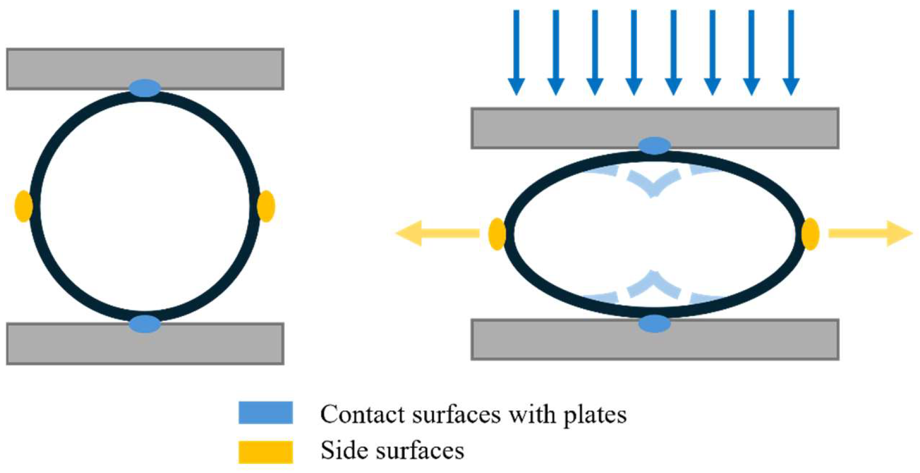
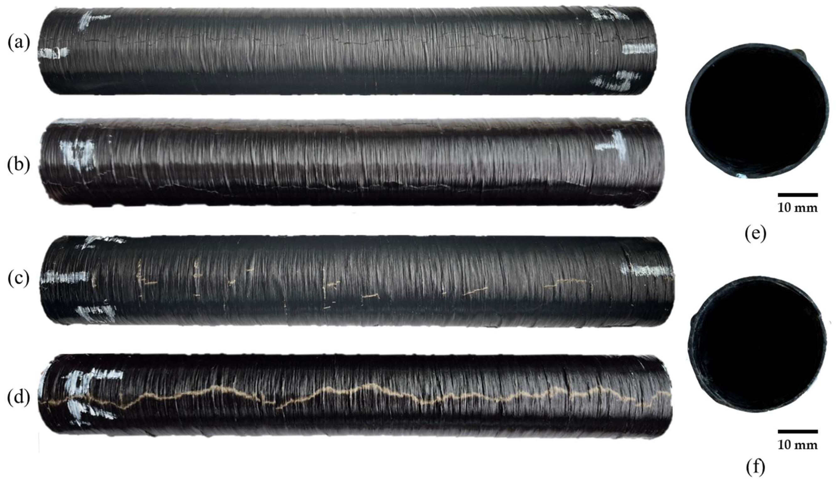
In order to understand the compressive behavior of CFRP and BFRP specimens, a preliminary macroscopic analysis of the fractured specimens was carried out. This assessment revealed that both CFRP and BFRP specimens exhibited a characteristic fracture pattern involving four distinct areas, two located at the contact interfaces between the specimen and the compression plates, and two along the lateral surfaces, as schematically reported in Figure 7.
Focusing on CFRP specimens, Figure 8a shows the typical fracture occurring at the contact surfaces with the plates. The damage is characterized by a continuous crack propagating along the entire length of the specimen, oriented perpendicularly to the fiber direction. This suggests a dominant failure mechanism driven by matrix cracking and fiber-matrix debonding under compressive stresses. A similar fracture morphology was also observed on the lateral surfaces of the CFRP specimens, indicating a relatively uniform failure behavior regardless of the fracture location (Figure 8b). On the contrary, BFRP specimens are characterized by a markedly different behavior at the contact interfaces, as shown in Figure 8c. BFRP specimens exhibit the fracture pattern characterized by localized and discontinuous damage, with few failure points distributed along directions perpendicular to the fiber orientation. This indicates a less pronounced crack propagation and suggests a different stress distribution or energy dissipation mechanism compared to CFRP. However, when considering the lateral fracture regions, BFRP specimens are characterized by a failure mode more similar to that observed in CFRP (Figure 8d). As a matter of fact, a continuous crack extending along the length of the specimen can be observed, perpendicularly oriented to the fibers. This suggests that, despite the differences observed at the contact interfaces, both composite materials are characterized by a comparable failure mechanism along the side surfaces under radial compression loading.
The cross-sectional images (Figure 8e,f) further clarify the deformation morphology along the specimen length under radial compressive loading. In particular, the images highlight the different damage localization patterns exhibited by CFRP and BFRP laminates. A slight residual ovalization of the cross-section can be qualitatively observed in CFRP specimens after testing, whereas BFRP specimens tend to preserve a more regular circular geometry despite the presence of more diffuse surface damage. This behavior is consistent with the different deformation and failure evolution mechanisms observed in the two composite systems.
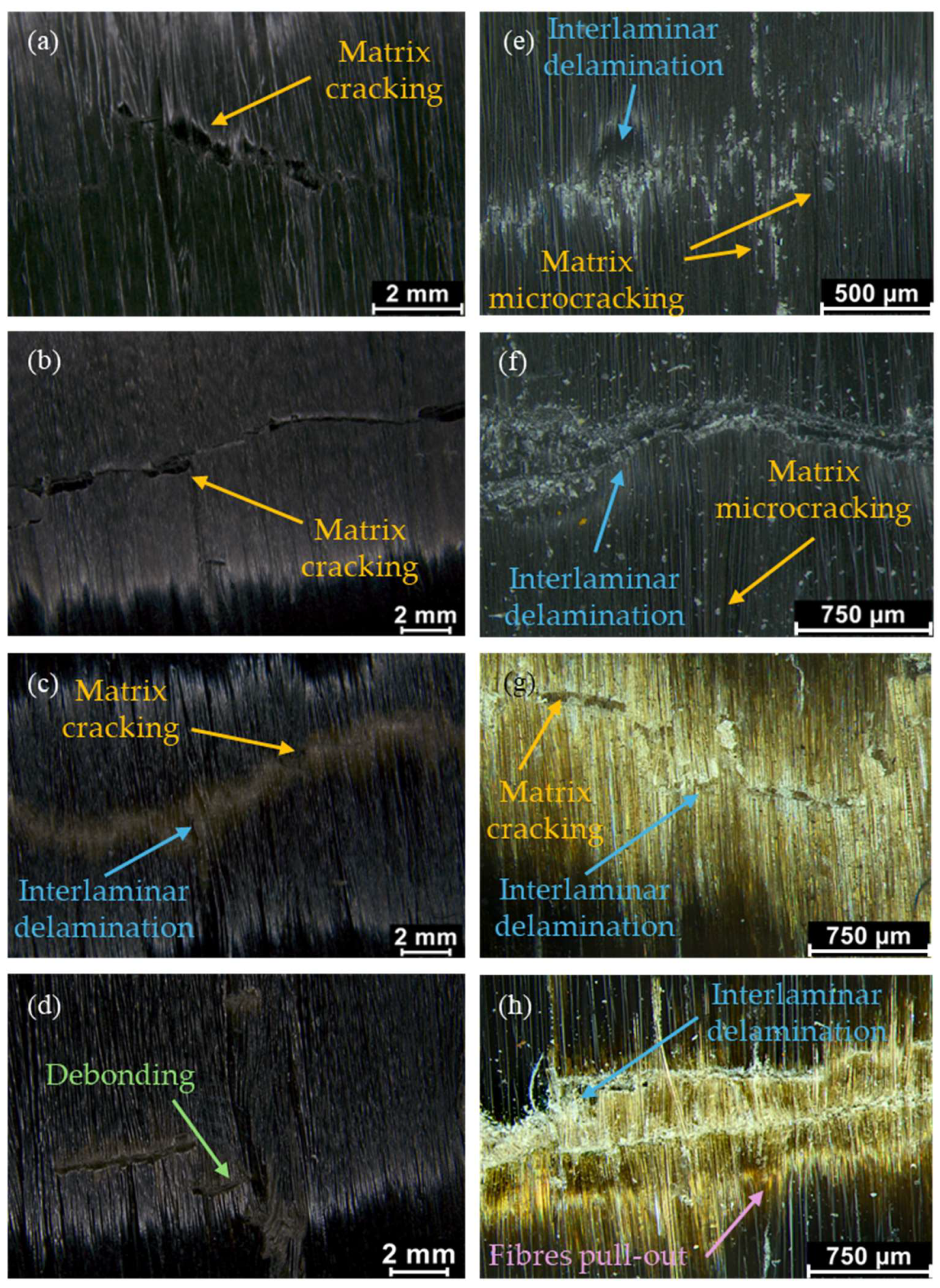
Then, a detailed fractographic analysis was carried out to better investigate the failure mechanisms of the CFRP and BFRP tested specimens. Specifically, the fracture surfaces were observed using the stereomicroscope Leica M205C, allowing for a more comprehensive observation of the damage mechanisms at different scales.
To this purpose, Figure 9 shows representative stereomicroscope images at two different magnifications of the fractured specimens subjected to radial compression tests. Specifically, Figure 9a,e and Figure 9b,f refer to CFRP specimens, showing the fracture morphology along the lateral surface and at the contact interface with the compression plates, respectively. Conversely, Figure 9c,g and Figure 9d,h show the corresponding fracture regions for BFRP specimens, respectively, along the lateral surface and contact interface.
It can be observed that the specimens exhibit different failure morphologies depending on both the fiber type and the fracture location. In particular, the damage evolution was dominated by the interaction between matrix cracking and interlaminar delamination mechanisms. The lateral surface of CFRP specimens (Figure 9a) is characterized by localized fiber splitting accompanied by matrix cracking predominantly oriented perpendicular to the fiber direction, indicating a brittle and fiber-dominated failure mechanism. At the contact interface with the plates (Figure 9b), crack propagation in the CFRP wound part occurs mainly parallel to the loading surface, suggesting failure induced by localized flexural stresses at the specimen–plate interface. On the contrary, BFRP specimens show a different damage evolution. Along the lateral surface (Figure 9c), pronounced fiber–matrix debonding and fiber pull-out can be observed, which are consistent with the lower stiffness and higher deformability of basalt fibers, as also evidenced by the mechanical test results. At the contact interface (Figure 9d), the fracture is characterized by multiple branching cracks combined with fiber rupture, indicating a more complex mixed-mode failure, indicating a mixed tensile and shear failure mode.
Higher magnification stereomicroscopy observations (Figure 9e–h) further clarify the local damage mechanisms involved in crack propagation. In CFRP specimens (Figure 9e,f), the fracture path is characterized by diffuse matrix microcracking accompanied by localized interlaminar delamination, indicating progressive crack coalescence along preferential interfaces. The relatively sharp and discontinuous crack morphology confirms the brittle nature of damage evolution in carbon-based laminates.
Conversely, BFRP specimens (Figure 9g,h) exhibit more extended interlaminar delamination combined with significant fiber/matrix debonding and localized fiber pull-out features. The wider damaged areas and the rougher crack morphology suggest enhanced energy dissipation during fracture, consistent with the more deformable response observed experimentally. These observations indicate that failure in BFRP specimens develops through a more progressive and complex damage evolution compared to CFRP laminates.

3.2. Axial Compression Test Results

In order to provide a comprehensive assessment of the compressive behavior and failure mechanisms of the investigated composites, axial compression tests were carried out on both CFRP and BFRP specimens in accordance with the ASTM D695 standard.
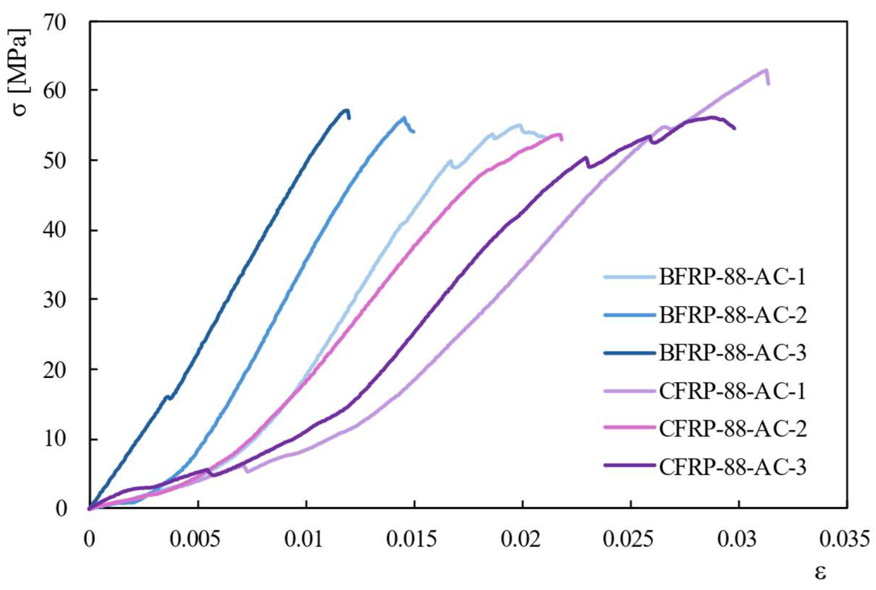
The axial compression tests provided load–displacement curves for each specimen, from which stress–strain curves were derived (Figure 10). Irrespective of the material taken into account, the stress increases with strain up to a peak value, corresponding to the onset of failure. Then, a sudden drop of stress can be observed, indicating a predominant brittle behavior.
As shown in Figure 10, both CFRP and BFRP composites exhibit similar peak compressive stress values. This result can be attributed to the loading direction, which is substantially perpendicular to the fiber orientation due to the high winding angle (88°). Under these conditions, the contribution of the fibers to the load-bearing mechanism along the loading direction is limited, and the mechanical performance is mainly governed by the polymer matrix and by the fiber–matrix interface. Therefore, despite the different reinforcement typologies, the use of the same epoxy resin in both CFRP and BFRP specimens contributes to similar compressive mean strength values experimentally observed, equal to 59.48 MPa for BFRP specimens and 59.87 MPa for CFRP specimens (Table 4). These comparable stress levels suggest that the failure initiation under axial compression is predominantly controlled by matrix-dominated deformation and interfacial damage mechanisms rather than by the intrinsic axial strength of the fibers. Similar observations were reported in previous studies on filament-wound composite tubes subjected to transverse or off-axis compressive loading [16,25].
However, when the compressive performance is normalized with respect to the specimen mass, a clear difference emerges between the two material systems. In particular, BFRP specimens exhibit an average specific strength of about 4.12 MPa/g, whereas CFRP specimens reach approximately 5.65 MPa/g. This discrepancy can be mainly attributed to the lower density of carbon fibers compared to basalt ones, which provides CFRP tubular components with a higher strength-to-weight ratio despite the similar absolute compressive strength values.
Consistent with the approach adopted for radial compression, the fractured specimens were analyzed both macroscopically and microscopically to better understand the underlying failure mechanisms.
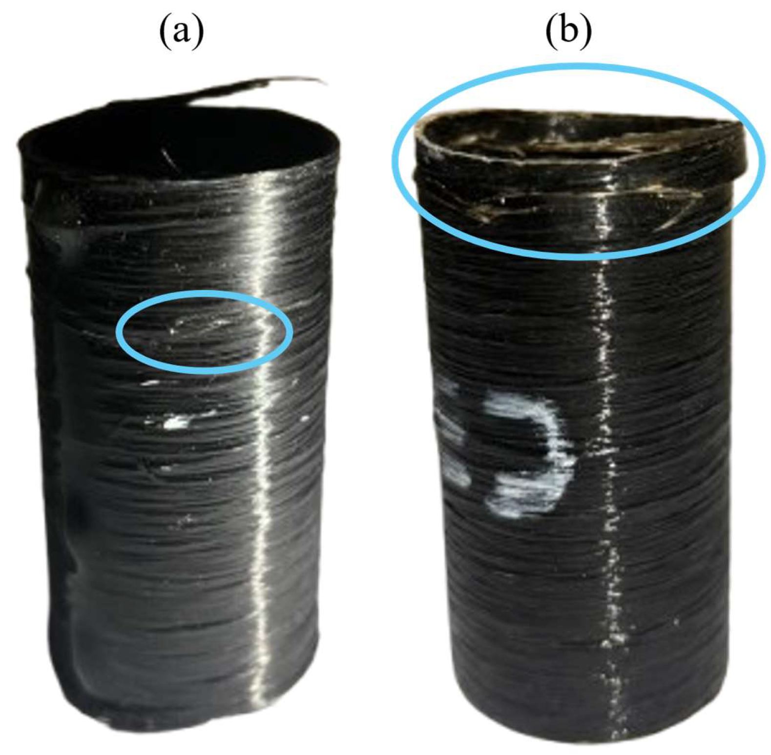
Figure 11 shows the typical fracture patterns observed after testing for CFRP (Figure 11a) and BFRP (Figure 11b) specimens after the axial compression tests. It can be observed that CFRP specimens fail in the central region of the sample (Figure 11a), whereas BFRP specimens tend to fracture near the lower end, in correspondence with the contact surface with the loading plate (Figure 11b).
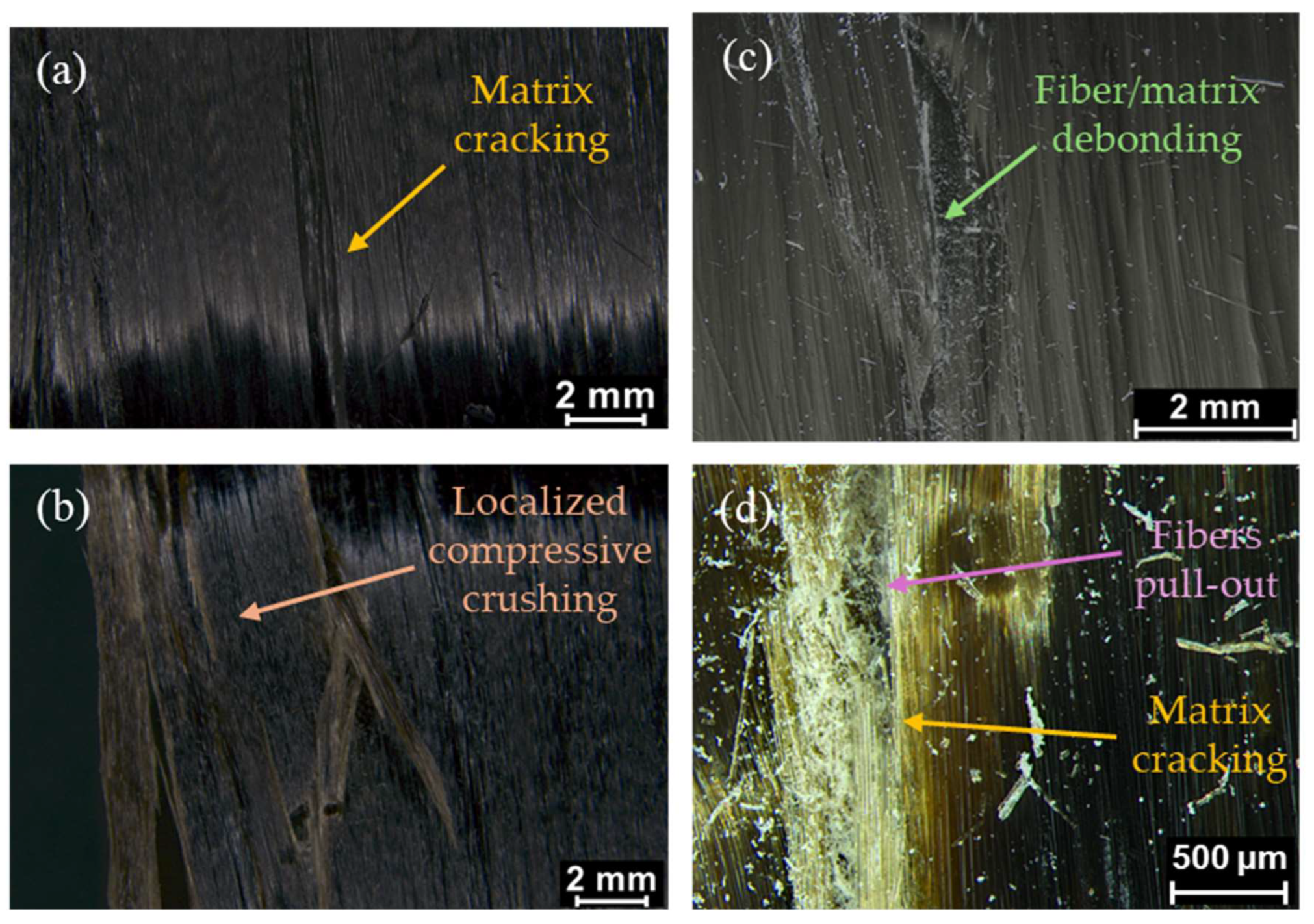
A more detailed investigation was carried out through stereomicroscopic analysis of the fracture surfaces, as shown in Figure 12. The CFRP specimen (Figure 12a) exhibits a brittle failure localized in the central area, characterized by cracking at the fiber–matrix interface. This failure mode is induced by compressive stresses that promote fiber–matrix separation, leading to crack initiation and rapid propagation. In contrast, BFRP specimens (Figure 12b) show a markedly different failure mechanism, with damage concentrated near the specimen ends. The observed features include significant fiber bending, extensive fiber–matrix debonding, and fiber pull-out. This result is indicative of an end-crushing failure mode, which demonstrates the lower stiffness and higher deformability of basalt fibers as compared to carbon fibers.
However, even though CFRP and BFRP materials exhibit similar compressive strength under axial loading, their failure mechanisms differ significantly, as they depend on the mechanical properties of the reinforcement phase and the interaction between the fibers and the matrix.
Higher-magnification stereomicroscopy observations further clarified the local damage mechanisms governing compressive failure in the investigated laminates. In CFRP specimens (Figure 12c), damage evolution is mainly characterized by longitudinal matrix cracking associated with localized crack propagation aligned with fiber direction. These features suggest a brittle compressive failure mechanism driven by local instability and rapid crack propagation, with limited damage diffusion and reduced energy dissipation capability. Conversely, BFRP specimens exhibit a more distributed and progressive damage morphology, characterized by extensive fiber/matrix debonding, diffuse interfacial degradation, and pronounced fiber pull-out phenomena. In addition, the presence of matrix cracking regions and localized fiber rupture indicates the activation of mixed compressive-shear failure mechanisms during the final stages of damage evolution. As observed for the specimens subjected to radial compression tests, the wider damaged areas observed in BFRP specimens confirm a more gradual failure process compared to CFRP ones, consistent with the higher deformability of basalt fibers.

4. Conclusions

The present work aimed to evaluate and compare the compressive behavior of tubular components in CFRP and BFRP composite materials realized by filament winding process, using a winding angle equal to 88°. To this purpose, radial and axial compression tests were performed, according to ASTM D2412 and ASTM D695 standards, in order to evaluate the mechanical properties of CFRP and BFRP tubular specimens. Finally, the fractured surfaces of the specimens were observed using stereomicroscopy analysis to investigate the main failure mechanisms developed during the compressive loading.
It was demonstrated that the fiber type strongly influences compressive behavior and damage mechanisms. Specifically, the main outcomes are summarized as follows:
Radial compression tests:
BFRP is characterized by a predominantly quasi-elastic behavior in a wide displacement range, with a gradual stiffness reduction before failure; on the contrary, CFRP shows a more brittle behavior, with earlier damage initiation and a more pronounced drop in load once the peak value is reached.
CFRP specimens are characterized by higher pipe stiffness values than BFRP ones by considering both the deflection values, equal to 5 and 10% of the diameter.
CFRP and BFRP tubular components exhibit similar failure modes along the lateral surfaces, characterized by cracks propagating perpendicular to the fiber direction. On the contrary, different compressive failure mechanisms at the specimen–plate interfaces were obtained: CFRP showed a more uniform and brittle failure characterized by continuous crack propagation and fiber-dominated fracture, whilst BFRP exhibited a more heterogeneous behavior, due to pronounced fiber–matrix debonding and crack branching.
Statistical analysis demonstrated that BFRP tubular specimens provide higher absolute mechanical performance under radial compression, with higher maximum load per unit length (66.78 vs. 42.91 N/mm), circumferential bending strength (1065.84 vs. 765.51 MPa), and energy absorption capacity (101.10 vs. 89.17 J) compared to CFRP. Conversely, CFRP exhibited significantly higher circumferential elastic modulus (75.28 vs. 42.84 GPa) and specific energy absorption (2.37 vs. 2.01 J/g), highlighting its higher stiffness and weight-specific efficiency. The relatively low standard deviation values confirmed the good repeatability and reliability of the experimental results.
Axial compression tests:
CFRP and BFRP are characterized by similar compressive strengths, confirming that the mechanical behavior is mainly governed by the matrix due to the loading direction perpendicular to the fibers;
CFRP exhibits a higher specific strength compared to BFRP, owing to its lower density, resulting in a higher strength-to-weight ratio;
Despite similar strength values, the failure mechanisms differ significantly: CFRP exhibits brittle, centrally localized failure driven by fiber–matrix cracking, whilst BFRP shows end-crushing behavior with fiber bending, debonding, and pull-out, reflecting its higher deformability.
Overall, BFRP provides a good alternative to CFRP for specific applications that do not require high performance, offering comparable mechanical properties with lower environmental impacts.
Future studies will concern the effect of the winding angle on the compression mechanical properties of tubular components realized via FW and how the hybridization of these structures can affect their mechanical behavior.

Author Contributions

Conceptualization, M.S.; methodology, C.M. and T.V.; software, C.M. and T.V.; formal analysis, M.S.; investigation, C.M. and T.V.; data curation, I.B.; writing – original draft, C.M. and T.V.; writing – review & editing, M.S.; visualization, I.B.; supervision, A.F. and M.S.; funding acquisition, A.F. All authors have read and agreed to the published version of the manuscript.

Funding

This research received no external funding.

Data Availability Statement

The original contributions presented in the study are included in the article, further inquiries can be directed to the corresponding author..

Conflicts of Interest

The authors declare no conflict of interest.

References

  1. Oğuz, Z.A.; Özbek, Ö.; Erkliğ, A.; Bozkurt, Ö.Y. Hydrothermal Aging Effect on Crushing Characteristics of Intraply Hybrid Composite Pipes. Eng. Struct. 2023, 297, 117011. [Google Scholar] [CrossRef]
  2. Annadorai, M.E.; Ramakrishna, M.; Jyothi, Y. Effect on Mechanical Properties of CFRP Composites in Different Fiber Orientations. Interactions 2024, 245, 198. [Google Scholar] [CrossRef]
  3. Forcellese, A.; Marconi, M.; Simoncini, M.; Vita, A. Life Cycle Impact Assessment of Different Manufacturing Technologies for Automotive CFRP Components. J. Clean. Prod. 2020, 271, 122677. [Google Scholar] [CrossRef]
  4. Timmis, A.; Hodzic, A.; Koh, L.; Bonner, M.; Schäfer, A.W.; Dray, L. Lifecycle Assessment of CFRP Aircraft Fuselage. In Proceedings of the 16th European Conference on Composite Materials, ECCM, Seville, Spain, 22–26 June 2014. [Google Scholar]
  5. Keiser, D.; Schnoor, L.H.; Pupkes, B.; Freitag, M. Life Cycle Assessment in Aviation: A Systematic Literature Review of Applications, Methodological Approaches and Challenges. J. Air Transp. Manag. 2023, 110, 102418. [Google Scholar] [CrossRef]
  6. Özbek, Ö.; Oğuz, Z.A.; Bozkurt, Ö.Y.; Erkliğ, A. Crashworthiness Characteristics of Hydrothermally Aged Intraply Glass/Basalt Composite Pipes. Mar. Struct. 2024, 97, 103656. [Google Scholar] [CrossRef]
  7. Sun, H.; Xiang, D.; Liu, Z.; Liu, L.; Harkin-Jones, E.; Wang, M.; Tan, W.; Luo, P.; Zhang, J.; Wang, B.; et al. Failure Analysis of Glass Fiber and Basalt Fiber Reinforced Polymer Composites under an Extreme Environment with High-Temperature, High-Pressure and H2S/CO2 Exposure. Polym. Compos. 2024, 45, 10124–10136. [Google Scholar] [CrossRef]
  8. Sarukasan, D.; Thirumavalavan, K. Investigation of Mechanical and Degradation Characteristics of Filament-Wound Composite Pipes Incorporating Basalt/E-glass Hybrid Reinforcement. Compos. Theory Pract. 2024, 24, 141–154. [Google Scholar] [CrossRef]
  9. Dhand, V.; Mittal, G.; Rhee, K.Y.; Park, S.J.; Hui, D. A Short Review on Basalt Fiber Reinforced Polymer Composites. Compos. B Eng. 2015, 73, 166–180. [Google Scholar] [CrossRef]
  10. Lopresto, V.; Leone, C.; De Iorio, I. Mechanical Characterisation of Basalt Fibre Reinforced Plastic. Compos. B Eng. 2011, 42, 717–723. [Google Scholar] [CrossRef]
  11. Singh, P.; Raghavender, V.; Joshi, S.; Pooja Vasant, N.; Awasthi, A.; Nagpal, A.; jasim Abd al-saheb, A. Composite Material: A Review over Current Development and Automotive Application. Mater. Today Proc. 2023; in press. [CrossRef]
  12. Almula, T.A.D.M.S.; Amori, I.H.; Yahya, M.Y.; Ayob, A. An Experimentally and Numerically Comparison between E-Glass/Epoxy and Basalt/Epoxy Pipes Pressurized Internally. Solid State Phenom. 2020, 305, 49–56. [Google Scholar] [CrossRef]
  13. Bianchi, I.; Forcellese, A.; Mancia, T.; Mignanelli, C.; Simoncini, M.; Verdini, T. Effect of Heat-Shrinkable Tape Application on the Mechanical Performance of CFRP Components Obtained by a Filament Winding Process. J. Compos. Sci. 2024, 8, 535. [Google Scholar] [CrossRef]
  14. Lapena, M.H.; Marinucci, G.; De Carvalho, O. Mechanical Characterization of Unidirectional Basalt Fiber Epoxy Composite. In Proceedings of the 16th European Conference on Composite Materials, ECCM, Seville, Spain, 22–26 June 2014. [Google Scholar]
  15. Kessler, E.; Gadow, R.; Weichand, P. Investigation of Mechanical Properties of Filament Wound Unidirectional Basalt Fiber Reinforced Polymers for Automotive and Pressure Vessel Application. In Proceedings of the ICCM International Conferences on Composite Materials, Copenhagen, Denmark, 19–24 July 2015. [Google Scholar]
  16. Özbek, Ö.; Bozkurt, Y.; Erkliǧ, A. Effect of Basalt Intraply Fiber Hybridization on the Compression Behavior of Filament Wound Composite Pipes. Int. Polym. Process. 2021, 36, 193–204. [Google Scholar] [CrossRef]
  17. Xiao, J.; Shi, H.; Tao, L.; Qi, L.; Min, W.; Zhang, H.; Yu, M.; Sun, Z. Effect of Fibres on the Failure Mechanism of Composite Tubes under Low-Velocity Impact. Materials 2020, 13, 4143. [Google Scholar] [CrossRef] [PubMed]
  18. Jones, B.H.; Li, M.-C. Liner-less Tanks for Space Application-Design and Manufacturing Considerations. In Proceedings of the 5th Conference on Aerospace Materials, Processes, and Environmental Technology, Huntsville, AL, USA, 16–18 September 2002. [Google Scholar]
  19. Zhang, T.Y.; Wang, J.; Ma, L.H.; Zhou, W. Damage Evolution and Failure Mechanism of Carbon Fiber Wound Composite Tubes under Lateral Compression. Polym. Compos. 2025, 46, S124–S138. [Google Scholar] [CrossRef]
  20. Quanjin, M.; Rejab, M.R.M.; Idris, M.S.; Hassan, S.A.; Kumar, N.M. Effect of Winding Angle on the Quasi-Static Crushing Behaviour of Thin-Walled Carbon Fibre-Reinforced Polymer Tubes. Polym. Polym. Compos. 2020, 28, 462–472. [Google Scholar] [CrossRef]
  21. Alkhatib, F.; Mahdi, E.; Dean, A. Crushing Response of CFRP and KFRP Composite Corrugated Tubes to Quasi-Static Slipping Axial Loading: Experimental Investigation and Numerical Simulation. Compos. Struct. 2020, 246, 112370. [Google Scholar] [CrossRef]
  22. de Menezes, E.A.W.; Lisbôa, T.V.; Almeida, J.H.S.; Spickenheuer, A.; Amico, S.C.; Marczak, R.J. On the Winding Pattern Influence for Filament Wound Cylinders under Axial Compression, Torsion, and Internal Pressure Loads. Thin-Walled Struct. 2023, 191, 111041. [Google Scholar] [CrossRef]
  23. Ishai, O.; Levi, H.; Altus, E.; Sheinman, I. Mechanical Performance of Thin-Walled Tubular Composite Elements under Uniaxial Loading Part 2: Compressive Behavior. Compos. Struct. 1995, 31, 171–175. [Google Scholar] [CrossRef]
  24. Özbek, Ö. The Influence of Fiber Orientation on Crashworthiness Behavior of Carbon Fiber Reinforced Composite Pipes. Eur. J. Eng. Sci. Technol. 2019, 2, 53–63. [Google Scholar] [CrossRef]
  25. Özbek, Ö.; Bozkurt, Ö.Y.; Erkliğ, A. An Experimental Study on Intraply Fiber Hybridization of Filament Wound Composite Pipes Subjected to Quasi-Static Compression Loading. Polym. Test. 2019, 79, 106082. [Google Scholar] [CrossRef]
  26. Cui, Z.; Liu, Q.; Sun, Y.; Li, Q. On Crushing Responses of Filament Winding CFRP/Aluminum and GFRP/CFRP/Aluminum Hybrid Structures. Compos. B Eng. 2020, 200, 108341. [Google Scholar] [CrossRef]
  27. Kessler, E.; Gadow, R.; Straub, J.; Kessler, E.; Gadow, R.; Straub, J. Basalt, Glass and Carbon Fibers and Their Fiber Reinforced Polymer Composites under Thermal and Mechanical Load. AIMS Mater. Sci. 2016, 3, 1561–1576. [Google Scholar] [CrossRef]
  28. Investigation of Mechanical Properties of Filament Wound Unidirectional Basalt Fiber Reinforced Polymers for Automotive and Pressure Vessel Application Basalt—Today (2018) |PDF| Composite Material|Fibers. Available online: https://it.scribd.com/document/618134297/Investigation-of-Mechanical-Properties-of-Filament-Wound-Unidirectional-Basalt-Fiber-Reinforced-Polymers-for-Automotive-and-Pressure-Vessel-Applicatio (accessed on 20 November 2025).
  29. Postacchini, L.; Simoncini, M.; Forcellese, A.; Bevilacqua, M.; Ciarapica, F.E.; Andreassi, G.; Russo, A.C. Environmental Assessment of an Automated Impregnation Process of Carbon Fiber Tows. Procedia CIRP 2020, 88, 445–450. [Google Scholar] [CrossRef]
  30. ASTM D2412-21; Test Method for Determination of External Loading Characteristics of Plastic Pipe by Parallel-Plate Loading. ASTM: West Conshohocken, PA, USA, 2021.
  31. ASTM D695-15; Standard Test Method for Compressive Properties of Rigid Plastics. ASTM International: West Conshohocken, PA, USA, 2022.
  32. Sadegh, A.M.; Budynas, R.G. Roark’s Formulas for Stress and Strain, 8th ed.; McGraw-Hill Education: New York, NY, USA, 2012. [Google Scholar]
  33. Timoshenko, S.; Gere, J.M. Theory of Elastic Stability, 2nd ed.; McGraw-Hill: New York, NY, USA, 1961. [Google Scholar]
  34. Jones, R.M.; Millard, R. Mechanics of Composite Materials Mechanics of Composite Materials, 2nd ed.; Library of Congress Cataloging-in-Publication Data; Taylor & Francis: Abingdon, UK, 1999. [Google Scholar]
  35. Daniel, I.; Ishai, O. Basic Concepts, Materials, Processes and Characteristics. In Engineering Mechanics of Composite Materials, 2nd ed.; Oxford University Press: New York, NY, USA, 2006; pp. 18–42. [Google Scholar]
Figure 1. X-Winder laboratory scale machine.
Jcs 10 00291 g001
Figure 2. (a) Curing cycle and (b) oven used for the curing process.
Jcs 10 00291 g002
Figure 3. (a) Radial and (b) axial compression tests of CFRP tubular specimens realized by filament winding process.
Jcs 10 00291 g003
Figure 4. Typical load vs. displacement curves obtained by radial compression test: (a) CFRP and (b) BFRP hoop wound specimens.
Jcs 10 00291 g004
Figure 5. Pipe stiffness and specific pipe stiffness obtained by radial compression tests of both CFRP and BFRP hoop wound specimens calculated at (a) Δy = 5%, and (b) Δy = 10%.
Jcs 10 00291 g005
Figure 6. Percentage comparison of the investigated parameters for BFRP and CFRP specimens subjected to radial compression tests.
Jcs 10 00291 g006
Figure 7. Schematic representation of the fracture surfaces of the specimens subjected to radial compression tests.
Jcs 10 00291 g007
Figure 8. Macroscopic observations of the fracture of specimens subjected to radial compression tests: (a) contact surface with plate, (b) side surface, and (e) cross-section of the CFRP specimen; (c) contact surface with plate, (d) side surface, and (f) cross-section of the BFRP specimen.
Jcs 10 00291 g008
Figure 9. Representative stereomicroscope images of the fractured specimens subjected to radial compression tests with different magnifications: (a,e) lateral surface and (b,f) contact interface with the plates of CFRP specimen; (c,g) lateral surface and (d,h) contact interface with the plates of BFRP specimen.
Jcs 10 00291 g009
Figure 10. Stress vs. strain typical curves of CFRP and BFRP specimens.
Jcs 10 00291 g010
Figure 11. Typical fractured specimens after axial compression tests: (a) CFRP and (b) BFRP specimens.
Jcs 10 00291 g011
Figure 12. Stereomicroscope images, at different magnifications, of the fracture in (a,c) CFRP and (b,d) BFRP specimens.
Jcs 10 00291 g012
Table 1. Geometrical, mass, and processing parameters of the realized specimens.
N. Layer: 2
Winding Angle: 88°
Inner Diameter: 35 mm
Length [mm]Thickness [mm]Weight
[g]
External Diameter [mm]
CFRP-88-RC-1Jcs 10 00291 i001298.21.3537.6237.7
CFRP-88-RC-2300.61.1038.2437.2
CFRP-88-RC-3297.31.1136.7537.2
CFRP-88-RC-4299.41.2137.7837.4
CFRP-88-AC-174.80.9810.6236.97
CFRP-88-AC-276.11.0511.0137.10
CFRP-88-AC-375.00.889.7936.77
BFRP-88-RC-1Jcs 10 00291 i002299.81.4950.5937.98
BFRP-88-RC-2298.21.5450.3338.08
BFRP-88-RC-3297.61.5150.0138.02
BFRP-88-RC-4299.41.5250.5238.04
BFRP-88-AC-175.41.0315.1437.07
BFRP-88-AC-274.91.0415.1537.07
BFRP-88-AC-373.20.9514.0936.90
Table 2. PS and specific PS values obtained for each tested specimen.
Δy = 5% Δy = 10%
PS [MPa]Mean PS
[MPa]
Standard DeviationSpecific PS [MPa/g]Mean Specific PS [MPa/g]PS [MPa]Mean PS
[MPa]
Standard DeviationSpecific PS [MPa/g]Mean Specific PS [MPa/g]
 CFRP-88-RC-1 8.809.075.47%0.230.249.108.883.23%0.240.24
CFRP-88-RC-29.510.258.950.23
CFRP-88-RC-38.400.238.390.23
CFRP-88-RC-49.590.259.070.24
BFRP-88-RC-16.225.745.76%0.120.116.325.984.64%0.120.12
BFRP-88-RC-25.750.116.090.12
BFRP-88-RC-35.690.115.940.12
BFRP-88-RC-45.290.105.560.11
Table 3. Mean values of the investigated parameters and differences between the two materials analyzed.
CFRPBFRPDifferences
qmax [N/mm]42.91 ± 4.08%66.78 ± 5.36% 55.6% 
σθ,bending [MPa]756.51 ± 5.22%1065.84 ± 5.58%40.9%
Specific σθ, bending [MPa/g]20.12 ± 4.06%21.16 ± 5.69%5.2%
Energy absortion [J]89.17 ± 4.50%101.10 ± 2.66%13.4%
Specific Energy absortion [J/g]2.37 ± 4.22%2.01 ± 2.40%−15.3%
Eθθ [GPa]75.28 ± 5.21%42.84 ± 4.39%−43.1%
Table 4. Max stress and max specific stress values reached by the investigated specimens.
Max Strength [MPa]Standard
Deviation
Max Specific Strength [MPa/g]
 BFRP-88-AC 158.712.28%3.88
258.354.14
361.394.33
Mean59.484.12
CFRP-88-AC162.964.32%5.78
256.635.33
360.015.84
Mean59.875.65
Disclaimer/Publisher’s Note: The statements, opinions and data contained in all publications are solely those of the individual author(s) and contributor(s) and not of MDPI and/or the editor(s). MDPI and/or the editor(s) disclaim responsibility for any injury to people or property resulting from any ideas, methods, instructions or products referred to in the content.