Article

Experimental Investigation of Low-Velocity Impact Response and Damage Behavior in Mono, Bi- and Tri-Hybrid Fiber-Reinforced Composites


by
Md. Mominur Rahman
1,2,*,
Al Emran Ismail
3,
Muhammad Faiz Ramli
3,
Azrin Hani Abdul Rashid
1,
Tabrej Khan
4,
Omar Shabbir Ahmed
4 and
Tamer A. Sebaey
4,5
1
Faculty of Engineering Technology, Universiti Tun Hussein Onn Malaysia, Johor 86400, Malaysia
2
Department of Textile Engineering, Faculty of Engineering, Daffodil International University, Dhaka 1341, Bangladesh
3
Faculty of Mechanical and Manufacturing Engineering, Universiti Tun Hussein Onn Malaysia, Johor 86400, Malaysia
4
Engineering Management Department, College of Engineering, Prince Sultan University, P.O. BOX 66833, Riyadh 11586, Saudi Arabia
5
Mechanical Design and Production Department, Faculty of Engineering, Zagazig University, Zagazig 44519, Egypt
*
Author to whom correspondence should be addressed.
J. Compos. Sci. 2026, 10(5), 230; https://doi.org/10.3390/jcs10050230
Submission received: 25 February 2026 / Revised: 21 March 2026 / Accepted: 24 March 2026 / Published: 26 April 2026

Abstract

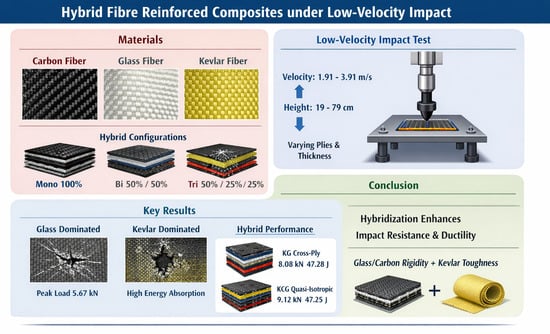
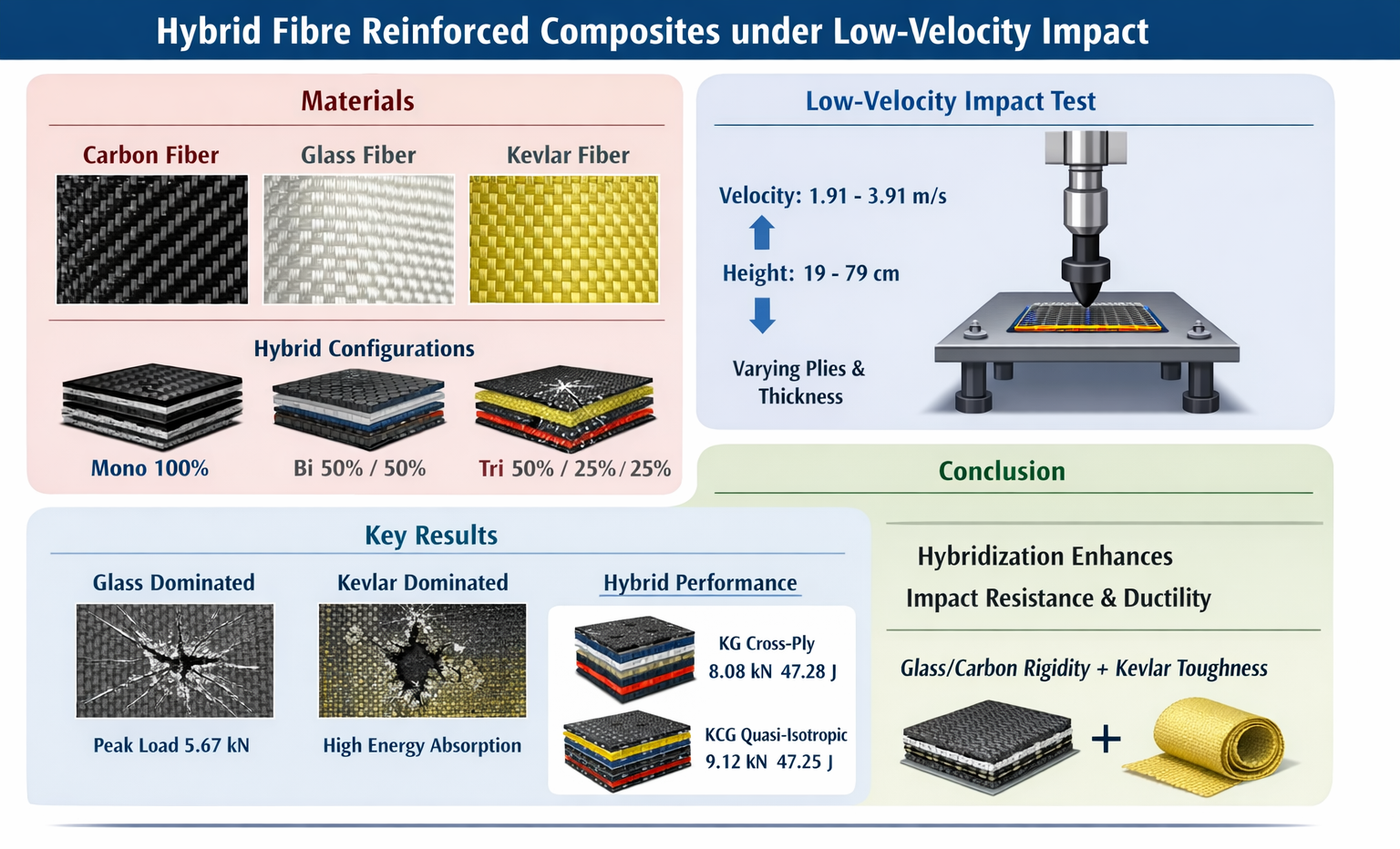
The need to create lightweight materials with better mechanical properties has led to the use of Fiber Reinforced Composites (FRCs)s in the aerospace and automotive industries. The mechanical behavior of FRCs is heterogeneous, especially in conditions of low-velocity impact (LVI). The impact events cause structural damage, where most of the available literature deals with mono- or bi-composites in controlled situations. This work will present the results of studying the behavior of mono, bi- and tri-hybrids with carbon, glass and Kevlar fiber-reinforced epoxy. The sequences of the laminate stacks, number of plies and laminate thickness in the drop weight testing were across velocities of 1.91 to 3.91 m/s at drop heights of 19 to 79 cm. The dominant pillars of LVI, such as peak load, energy absorption and the modes of damage, were analyzed. The glass-dominated laminates peaked at 5.67 kN, while the Kevlar-dominated laminates reached peak flow in ductile collapse with greater quantities of absorbed energy. The leaders in strength and energy were the hybrids of Kevlar–glass (KG) cross-ply at 8.08 kN and 47.28 J and quasi-isotropic Kevlar–carbon–glass (KCG) at 9.12 kN and 47.25 J, showcasing a balance of strength and toughness. The rest, holding a greater quantity of Kevlar, ranging in thickness and cross-plies, were shaped with a load center. The experimental conclusion is that hybridization improved impact resistance and ductility, which is best supported by the glass/carbon rigidity-layered laminates. Such understanding directs the design work of future composite materials for better impact control.

Graphical Abstract

1. Introduction

The application of fiber-reinforced composites (FRCs), due to their high specific strength and stiffness, has gained immense popularity in the aerospace and automotive industries due to the need to improve the fuel efficiency, along with the environmental performance, of vehicles. Although the reliability of designs fashioned with FRCs is still a subject of debate due to the intricate structures and heterogeneous nature of the FRCs, their benefits are undoubted [1]. With high and complex volumes, FRCs are not isotropic materials, as their mechanical responses depend on a range of shifting interrelated factors, such as the fiber type (glass, carbon, or Kevlar), the volume of the fiber, the sequence in which the fiber is stacked, and the number of plies and thickness of the laminate [2]. With shifting parameters to consider, this complexity is especially troubling with dynamic loading, and even more for low-velocity impact (LVI), which tends to exhibit critical damage that is not easily visible and often ignored [3].
The rapid energy transfer and intricate damage that occur during LVI are contingent on the geometry and velocity of the projectile, as well as the laminate architecture. The impact, peak load, and energy absorption that are widely documented are due to the compositions of the materials, including the fiber–matrix, and their stacking designs [4]. Take, for example, the disparity between the energy absorption of composites that have been impregnated with PSTF versus composites with a mass fraction of TSTF. The 3D glass fabrics tend to provide a lower peak force to the materials, which is a counter-phenomenon, as more energy absorption leads to a peak force that is reduced due to a greater amount of deformation and toughness. These numerous examples ultimately illustrate the lower range of stiffness that is desired along with the damage tolerance [5,6].
How different materials behave under low-velocity impact (LVI) varies greatly. On the one hand, glass/epoxy composites sustain high peak loads, but very little displacement. On the other hand, tougher bio-fiber composites, such as kenaf/epoxy, sustain loads and simultaneously absorb greater amounts of energy. Non-hybrid carbon/epoxy laminates sustain the highest peak loads of all composites, while aramid/epoxy laminates sustain the lowest peak loads. Testing accuracy is sometimes very high, as the errors obtained from peak load–displacement analysis are less than 5%. Furthermore, more than 10% fiber volume in hemp/polyester composites results in more than double the peak load capacity [7].
The environmental and matrix conditions have effects on fiber–matrix composites, too. For instance, the abaca/epoxy composite is more impact-resistant than the abaca/rubber hybrid composite, even though the latter sustains more impact energy. Those with more than five plies tend to absorb less energy than those with fewer than five plies. Bilayer hybrids with high strain to failure, having lower impact energy, demonstrate the mechanical and other material behaviors that dominate the response to LVI [8].
In the same way, the impact energy absorption characteristics in fiber-reinforced composites (FRCs) also form an interesting concert of material characteristics, low-velocity impact behaviors, and multiple failure modes. Although the impact energy and the absorbed energy functions are regularly linear, the impact energy and absorbed energy exhibit a much more interesting correlation with distinct failure modes [9]. The way in which different materials absorb energy and undergo impact damage is also distinct. For example, most hybrid composites tend to absorb more energy than their reinforced counterparts, demonstrating the synergistic effect of different fiber ratios [10]. Unfortunately, it has been shown that flax specimens absorb more energy but display lower-energy impact damage and larger damage extension than glass–flax composites [11]. The range of materials used heightens the performance range. It has been shown that impact testing of Carbon Fiber/Poly ether-ether ketone (CF/PEEK) and CF/Epoxy composites demonstrates that the former is superior in low-velocity impact performance [12]. The difference in matrix materials is a strong influence on the dissipation of energy. Kevlar composites are no exception and possess an amazing relationship between fiber configuration and energy absorption characteristics.
Among all configurations of G/G/G and K/G/K composites, K/K/K composites have the greatest absorption potential, while the three-fabric hybrids lag behind the neat Kevlar and two-fabric sandwich composites [13]. The difficulty of such an array of fiber combinations and configurations within the laminate highlights the need to look beyond the attributes of the constituent fibers and consider the effects of fiber combinations and arrangements. Again, as with the stacking sequence, in one study with basalt and Kevlar composites, the H-1 composite with alternating stacking gained more energy absorption than the Kevlar polypropylene and H-2 composites with different stacking sequences, with H-2 having more than H-1 [14].
Disregarding such impact, the absorption of energy by the composite is important as it provides protection to the structure it shields from the impact. It is measured by the area under the load displacement curve [15] and is a function of the mean load applied, specific energy absorption, and volumetric energy absorbed. In the low-velocity impact scenario, basalt composite 100B shows the highest maximum force, while nylon 100N has the lowest, exemplifying the mechanical signatures of the fibers [16]. Enhanced energy absorption is a characteristic of hybrid composites. For example, FCFCF and CFFFC flax–carbon hybrids outperform their non-hybrid counterparts by 13.25% and 28.89% respectively [17], illustrating the fiber combination effect.
Like with laminates of 3D fiber orientation, which are superior to all 2D laminates of the same reinforcements and all other reinforcements, it still shows the role of fiber architecture on the impact energy dispersion and absorption [18]. Within the same class of materials, additional subtleties arise. Single-ply 3D orthogonal woven fabrics possess a higher energy absorption capability than unidirectional or 2D plain woven fabrics, as a result of the efficient stress transfer in the yarn matrix [19,20]. It is puzzling, though, how the incorporation of nano-clay or nano-fibers decreases impact energy absorption [4,5]. It is, however, beyond material composition that the importance of processing and configuration becomes clear. Fiber volume fraction is a prime example of a composition that significantly increases total energy absorption [21]. Likewise, the stacking sequence is one of the variables that determines the dynamic response of composite plates [22]. These systems also add to the environment. The presence of cavitation in the composite before major failure can greatly aid in energy absorption [23]. The matrix type assists in controlling the energy loss, with composites of flax and MAPP exerting higher perforation resistance than epoxy-based composites [24].
Force and displacement, however, have also been defined as main parameters to determine the mechanical properties of composites.While impact energy is often correlated with maximum displacement in a linear manner for CFRPs with protective layers, the behavior of the peak force with respect to velocity, time, and displacement shows greater disparity for different materials and configurations. Hybrid structures show, for instance, an increase in maximum displacement and impact energy with the increase in impact energy. This is not the trend for all hybrid configurations; CCCG laminates, for instance, show different behavior. It is not only the simple trends in a space–time description for the response to an impact that are important. The location of impact is also vital. Impacted areas often exhibit negative loading that gets deformed more than areas that are subjected to distributed loading. The material properties of peak force are also appreciable, especially with the addition of CNTs. CNT composites show higher peak forces than composites without CNTs. Auxetic laminates show an impact behavior that is greatly fascinating due to the negative Poisson’s ratio. These laminates consistently, with the increase in impact energy, also show the maximum reduction in displacement.
The effects of increased impact on modifier peak rates suggest that increased force contact times on their plate below threshold KX mostly depend on plate thickness [25]. Also, the impact one body has on another in motion is not constant, and increased speed produces displacement in greater drag layers [26]. Stacking configurations in composites also add a further dimension. Studies show that K/K/K Kevlar-based composites are the most impact-resistant of all conflicting arrangements, illustrating the benefits of efficient fiber laminate stacking design [27].
From the perspective of performance parameters of FRCs, impact force and energy are defined and interrelated by a set of specific parameters, such as impact force, energy absorption, and damage progression. Impact energy and peak force are indeed positively correlated, but the threshold load that initiates severe damage is usually constant regardless of the increasing level of energy applied [27]. This indicates that beyond a certain force level, energy absorption accelerates while impacts, which can be periodic in nature, may be superficially damaging with little to no visible surface damage [28]. As is often the case with hybrid structures, the behavior does not become simplified but instead has a further level of intricacy added.
As the impact energy increases, the threshold load and energy absorption onto hybrid structures also tend to increase [29]. This indicates the presence of a synergistic effect, wherein different material components combine and function to redistribute and absorb energy more efficiently. However, accompanied by the high energy, there is a price to pay. Increased energy levels tend to increase the peak force, shorten the impact duration, and increase the severity of interlaminar damage to the composite [30]. The impact location is also important. Low-energy impact at the nodal points of a composite sandwich structure may lead to localized crushing damage, which, as paradoxical as it may seem, results in efficient energy absorption even when the energy expenditure is high [31].
In contrast, the damage diagnostics, in most cases, consist of mechanical property assessment against the applied load, which often is a low-velocity impact. There are various types of damage, which may be classified as delamination, matrix cracking, fiber breakage and fiber–matrix debonding [32,33,34]. A closer examination re-vitalizes the notion of symmetry breaking, which, although modulated by a broad umbrella of influence, remains under dynamic interdependence.
Delamination damage is the most frequent type of damage and is associated with an increase in the reduction of energy absorption and load-bearing capacity [35]. Nonetheless, its peculiar behavior has a linear impact energy and impact location pattern [1]. The pattern of damage can be symmetric, circular, and embroidery-like at the center of the impact, and even zigzag at higher velocities [26,36,37]. Moreover, damage has a sequenced time, which is a convex combination of simultaneous and interval damage. Matrix cracks precede fiber breakage. Cracks usually initiate in the 90-degree layer and soak loosely with increased impact energy [4]. Hyperstatic, this combination with the addition of the tension and compression inter-matrix damage cycle shapes the damage and failure behavior of the composites [38]. The designs and materials used to construct the composites have an enormous effect on the type, extent and location of the damage. For example, 3D braided composites with no defects exhibit a significantly higher damage volume than defective composites [39]. The type of fabric used in hybrid structures has a measurable effect on damage patterns, with the average areas of fabric-type damage patterns, in descending order, starting with aramid fabric. I do not need to say more. There are so many parameters, including fiber angle, stitching, and stacking, that matter [4,40,41]. Other issues matter, like the material composition. HFRP composites show greater internal damage and diminished compressive strength because of the presence of carbon fibers compared with flax skin composites [42] Conversely, the type of resin used can also influence the damage profile, with studies suggesting better damage tolerance for epoxy resins compared with bismaleimide under impact [30]. Impact parameters, such as energy level, further add to the intricacy. While an increase in damage area and volume is observed with increasing energy, some materials exhibit peak resistance at a specific energy level [6,36].
Despite the existence of a significant number of studies on impact properties and their induced damage, there is still a lack of evidence found as limitations lie in single- or bi-hybrid fiber-constituted reinforced composites, mainly carbon-dominated laminates, besides simulation-based investigations. The present study represents an extension of previous tri-hybrid research as it evaluates mono (100%), bi-hybrid (50–50%), and tri-hybrid (50–25–25%) laminates in a single sound framework. Unlike previous studies that included configurations in only limited configurations, this data set includes two stacking sequences (cross-ply and quasi-isotropic) and three numbers of plies (4, 8, and 12) with varied thicknesses under low-velocity impact ranging from 1.91 m/s to 3.91 m/s and impact energy heights ranging from 19 cm to 79 cm. Therefore, this work aims to address the gaps by experimenting on a broad suite of fiber-reinforced composites with their full-fledged low-velocity impact properties and classification of their induced damages. This allows one to directly compare the effects of hybridization, orientation, and thickness. Furthermore, the combination of load–time and load–deflection responses, together with microscopy-based damage analysis, gives deeper insight into post-peak damage mechanisms. Hence, through the dataset, we can have a more comprehensive and cross-comparable understanding of hybrid composite behavior.

2. Materials and Methods

2.1. Composite Preparation

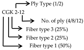
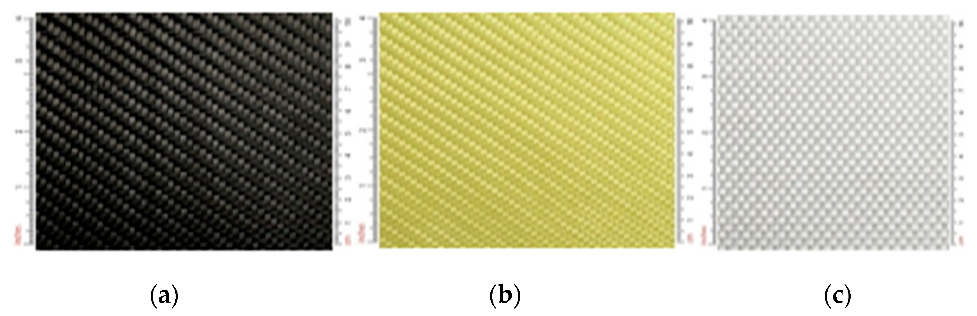
This research utilized three types of woven reinforcement fabrics: carbon, Kevlar, and glass fiber, incorporating both twill and plain weave architectures. Table 1 contains the specifications of these fabrics, while Figure 1 illustrates them visually. The composite laminates were constructed using the unmixed thermoset epoxy resin system with the hardener at a weight proportion of 1:2. A regimented wet lay-up technique was utilized, in which the weight of the resin solution equaled the weight of each individual reinforcement cloth layer. To achieve full saturation and process losses, 15–20% of the resin solution was prepared. An elaborate experimental matrix was constructed, which had three different clusters. Each of these clusters contained three material groups constituting nine different composites in total. Samples manufactured for each type were six in number. Of these, three were cross-ply with an orientation of [0°/90°/90°/0°]s, and three were quasi-isotropic with an orientation of [45°/0°/−45°/90°]s, with 4, 8, and 12 ply counts for each orientation. The configuration of the clusters is illustrated aside. This clustering technique is summarized in Table 2. Notably, the choice of materials and experimental parameters was performed in order to systematically study the effects of hybridization, orientation of fibers, and thickness of the laminate on low-velocity impact behavior. Mono (100%), bi-hybrid (50–50%) and tri-hybrid (50–25–25%) fiber volume fractions were used to investigate the progressive interaction of different fiber types. Two stacking sequences, cross-ply (0/90/90/0) and quasi-isotropic (45/0/–45/90), were considered to represent orthotropic and multidirectional mechanical responses. Laminates in the combination of 4, 8 and 12 plies were produced to test thickness-dependent impact resistance and energy absorption properties.
  • Cluster 1: Mono-constituents, featuring a 100% composition of carbon (C), Kevlar (K), and glass (G).
  • Cluster 2: Bi-constituent hybrids, with a 50–50% composition of carbon–Kevlar (CK), carbon–glass (CG), and Kevlar–glass (KG).
  • Cluster 3: Tri-constituent hybrids, with a 50–25–25% composition of carbon–glass–Kevlar (C2GK), Kevlar–carbon–glass (KCG), and glass–carbon–Kevlar (GCK).
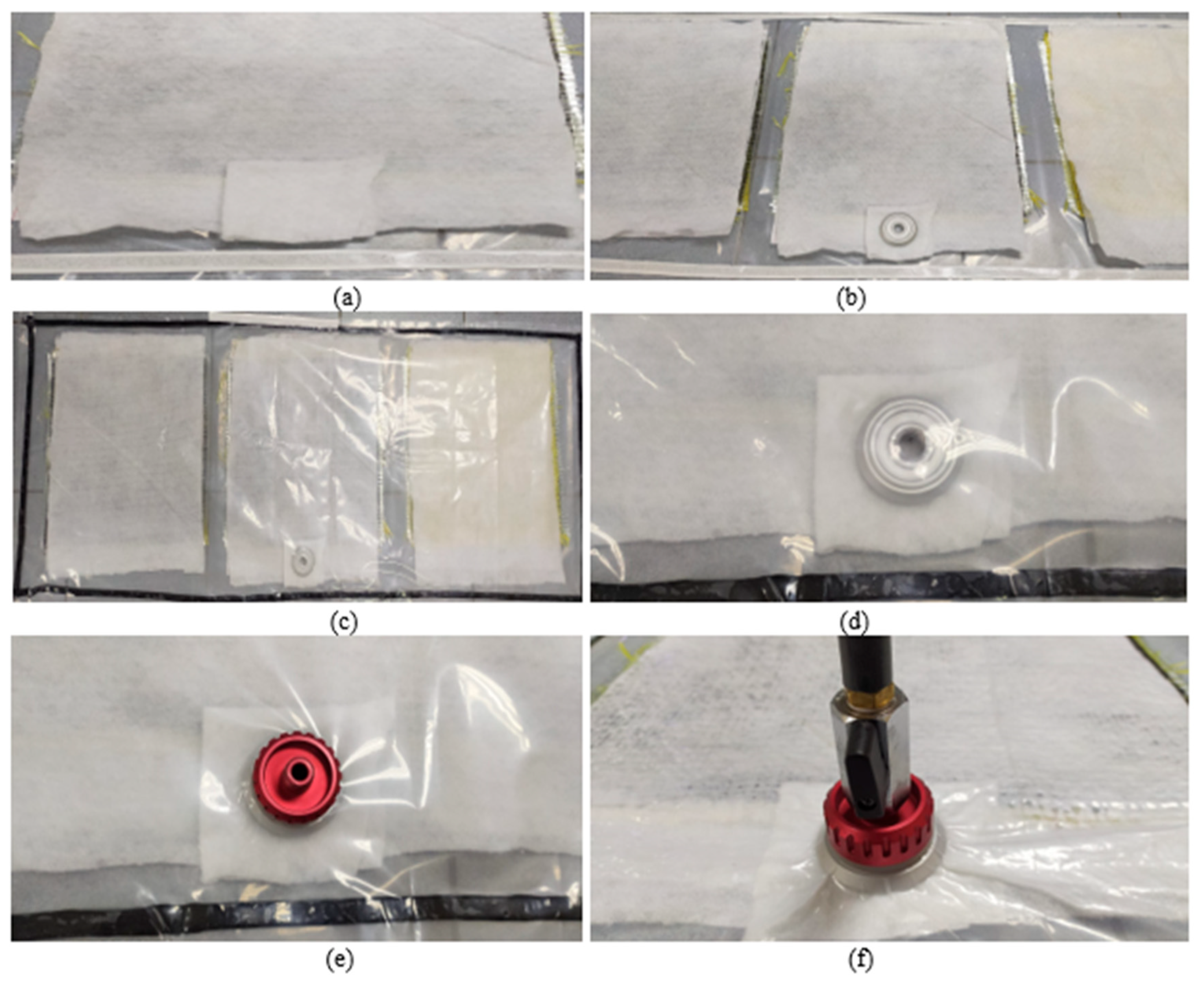
Rectangular composite plates were fabricated in 3 clusters, each having 3 groups, so a total of 9 types, each having 6 samples (3 for cross-ply and 3 for quasi-isotropic for the same number of plies of 4, 8 and 12). The first cluster was pure/mono-constituents having a 100% composition of carbon (C), Kevlar (K) and glass (G), while the second cluster was hybrid bi-constituents having a 50–50% composition of carbon–Kevlar (CK), carbon–glass (CG) and Kevlar–glass (KG). The final and third cluster was hybrid tri-constituents having a 50–25–25% composition of carbon–glass–Kevlar (CGK), Kevlar–carbon–glass (KCG) and glass–carbon–Kevlar (GCK). The fabrication process involved two distinct lay-up orientations, such as cross-ply [0°/90°/90°/0°]s and quasi-isotropic [45°/0°/−45°/90°]s. For instance, the full cluster details are presented in Table 2. In the layering of the face and back side of the laminate, the Kevlar cloth layer was prioritized for its superior damage resistance and energy absorption, followed by carbon and then glass. The manufacturing employed a manual wet lay-up technique combined with vacuum bagging. Apart from this, a few images of the manufacturing processes are shown in Figure 2. Reinforcement cloths were cut to 325 mm × 325 mm dimensions using a thick paper template, paying careful attention to maintaining the specified angles of 0°, 90°, 45, and −45°. The plies were stacked sequentially as per the lay-up designated sequence, with resin being applied on each layer to ensure impregnation. Stacking was done, and peel-ply and breather/bleeder fabric were added on top to absorb excess resin and aid air removal. The assembly was then sealed in a vacuum bag using sealant tape. A vacuum-fitting was attached, and the bag was attached to a pump. A vacuum was applied and held for 4–6 h after making sure there were no leaks with a vacuum gauge. The layering process involved sequentially arranging the cut cloths in the vacuum bag setup, followed by application of the epoxy-hardener solution, paying particular attention to the 22 min pot life. The laminates underwent a 24 h ambient temperature cure cycle before being demolded.

2.2. Low-Velocity Impact Testing

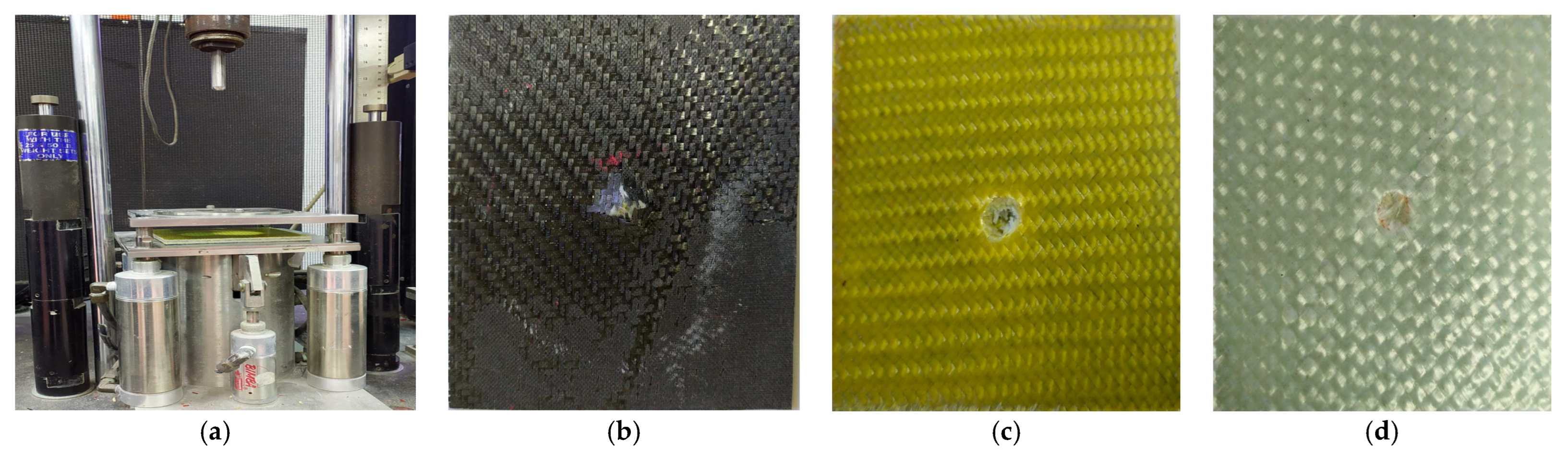
The composite specimens were tested in accordance with the details given in Table 3. The tests were conducted strictly according to the established standards of the procedures of the ASTM D7136. A Drop Weight Impact Tower (Instron, Norwood, MA, USA) was used to characterize the low-velocity impact response. The table includes the critical test configurations. The raw and consolidated data outputs are pointedly enumerated and contain important low-velocity impact characteristics. Notably, for the impact tests, a variety of drop heights were used, which corresponded to the impact velocities, as this was done to capture the material’s behavior for various energy levels. Apart from this, the test setup and images of the specimens for low-velocity impact are shown in Figure 3a and Figure 3b–d respectively. Notably, the impact tests were carried out in compliance with the scope and requirements, namely, the standards proposed under the method of standardization (ASTM D7136), and drop heights of 19–79 cm were used, corresponding to velocities of 1.91–3.91 m/s, which ensured low-velocity impact conditions. Multiple response parameters, such as peak force, absorbed energy, displacement, and extent of damage, were examined to give an overall impact performance analysis.
Figure 3. (a) Testing setup of low-velocity impact in Drop Weight Impact Tower; (bd) different images of tested specimens.
Jcs 10 00230 g003

2.3. Material Characterization

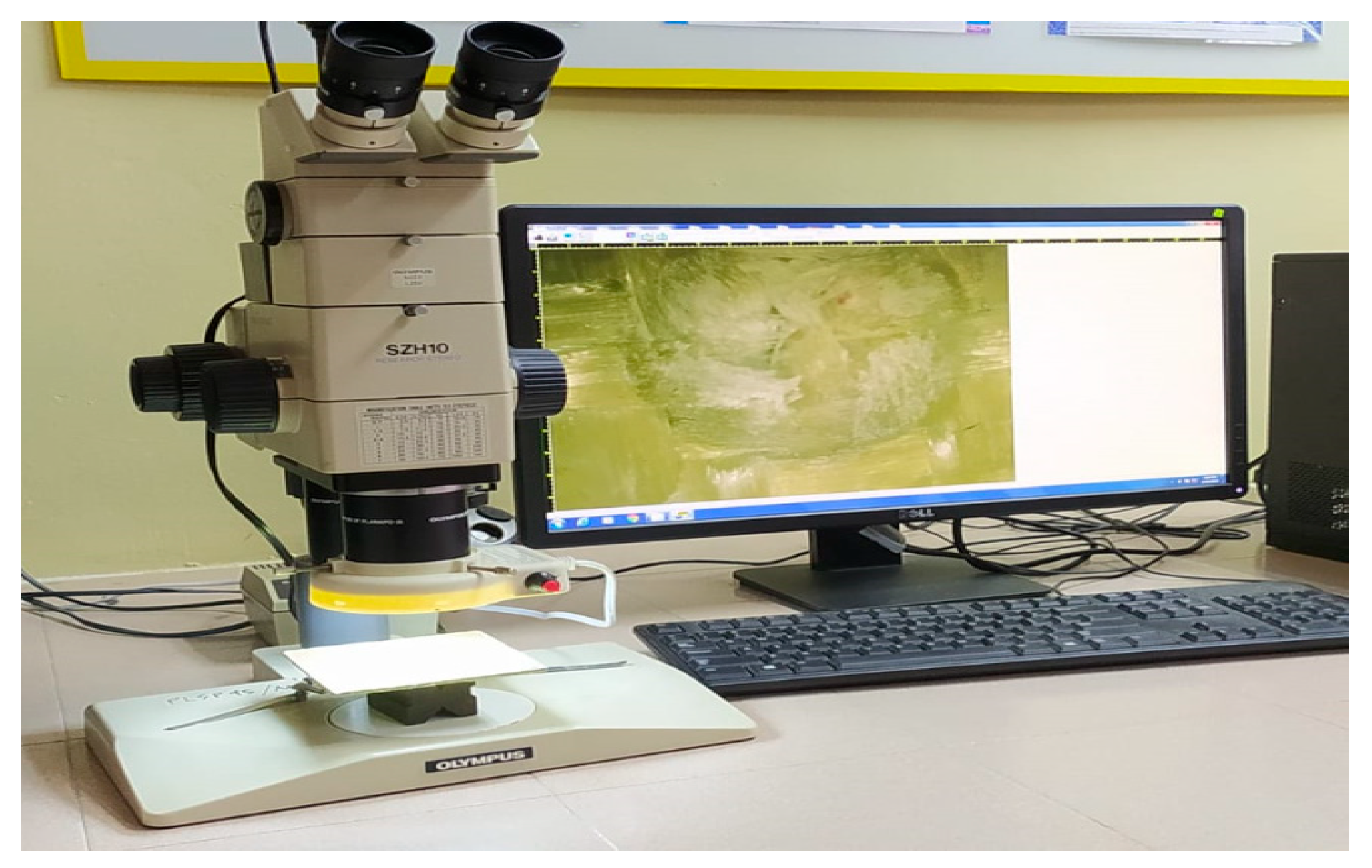
The main failure types, such as delamination, matrix cracking, fiber breakage, perforation and fiber buckling, of drop weight impact-tested specimens were investigated and inspected, firstly by visual inspection and later verified by the optical microscopy method with a microscope of the material characterization lab in terms of magnifications of 7, 10, 15, and 20. Notably, the optical microscope was from the OLYMPUS brand (model: SZH10) by Olympus Optical Co. Ltd., Tokyo, Japan, which is shown in Figure 4. Microscopy regions were systematically chosen from optical images, considering three proper regions, i.e., the impact center, the near impact region, and the outer damage zone. All specimens were sectioned through the impact axis in order to ensure similar through-thickness visualization of damage. Damage categorization was standardized with the establishment of certain criteria, such as matrix cracking, perforation, fiber buckling, delamination and fiber breakage based on individual morphological features under the optical microscope. A set of identical preparations of samples and a fixed set of magnification levels were observed in all the cases to maintain consistency. This approach reduced the subjectivity and allowed direct comparison between the damage modes of mono, bi- and tri-hybrid laminates.

3. Results and Discussion

3.1. Load Versus Time and Deflection

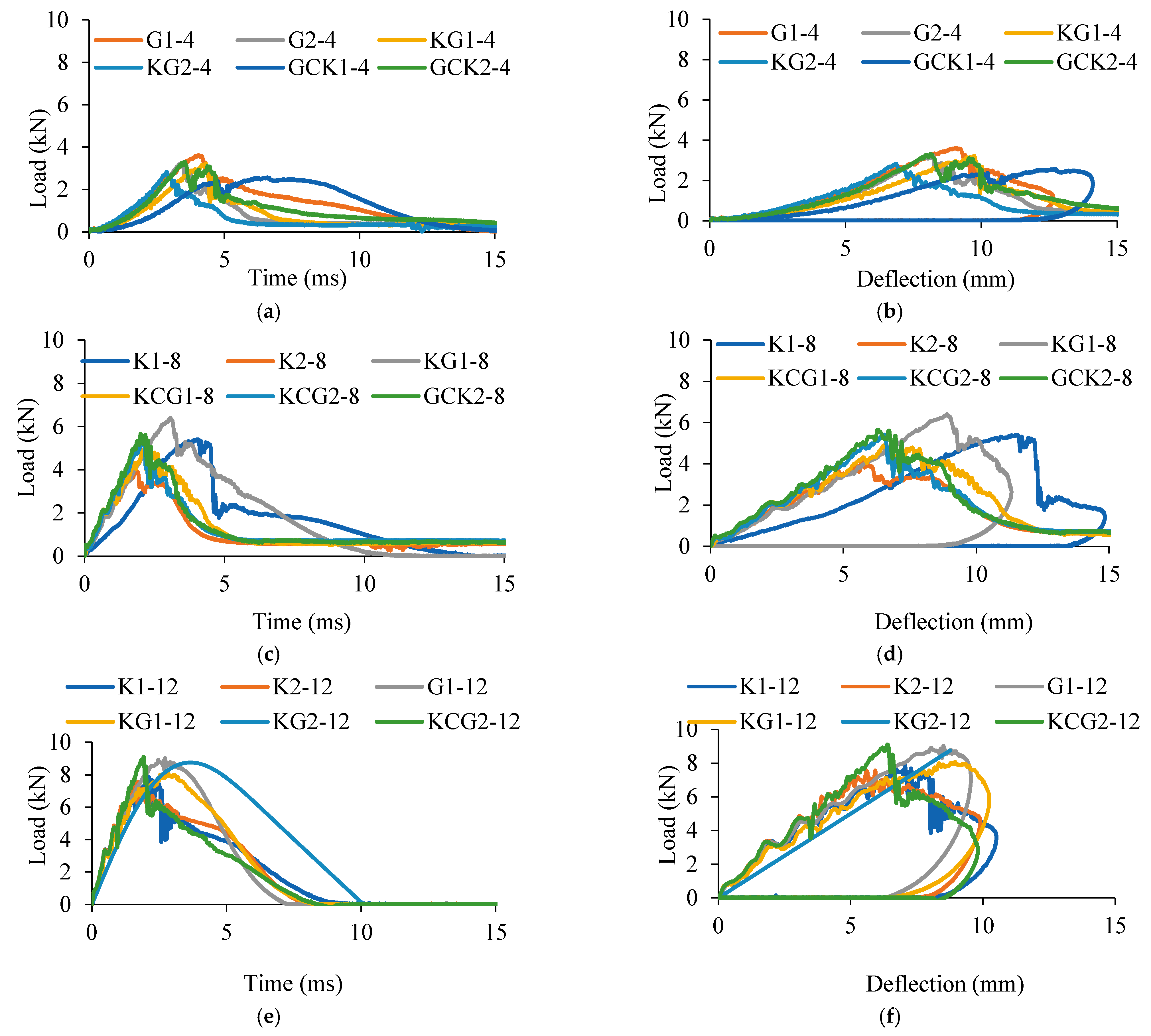
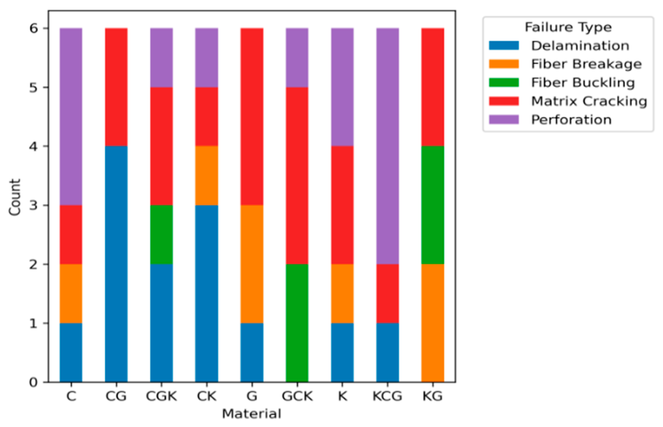
The low-velocity impact (LVI) performance of composite laminates is a complex process between the macroscopic mechanical response of composite laminates and the microscopic failure mechanisms that control the damage pattern. Analyzing the load–time/deflection behavior along with the resultant failure modes gives one a holistic idea about their damage tolerance and energy absorption capacities. The mechanical response, as described in Figure 5 for the best-performing six specimens of each, for load versus time and load versus deflection for four-, eight- and 12-ply laminates, shows that distinct behavioral patterns can be identified as they relate directly to fiber composition. Carbon-dominant laminates were consistently characterized by an extremely sharp increase to peak load, followed by a dramatic decrease in both the load–time and load–deflection curves. This signature brittle failure is characterized by a minimum of plastic deformation and does not result in much energy absorption, which is evident by the low values in Figure 5a,b for four-ply carbon samples ranging from 6.01 to 7.14 J. This response is microscopically explained by the presence of perforation and catastrophic fiber breakage, which are low-energy failure modes, as can be confirmed in Table 4, with perforation showing the lowest energy average energy absorption of 21.74 J.
In stark contrast, Kevlar-based laminates exhibited a ductile response in which load could be sustained over longer periods of time and larger deflections. This is supported by a broad load–time curve and significant deflection at failure for K2-4, which is up to 19.3 mm, resulting in better energy dissipation, such as 38.33 J for K1-8 in Figure 5c,d and 46.8 J for K1-12 in Figure 5e,f. This macroscopic behavior is intrinsically related to failure behavior mechanisms that encourage accumulations of energy to occur. As per Figure 6 and Table 4, Kevlar-dominated composites tend to experience fiber buckling and breakage, which are the failure modes associated with the highest average peak loads and energy absorption of 36.80 J and 37.66 J, respectively. The ductile nature of Kevlar allows for high degree of fiber stretching, fibrillation and pull-out, which leads to a prolonged post-peak damage phase that efficiently dissipates energy, which is indicated by the considerable maximum load-to-failure intervals for the best performing materials like KG and K. Glass fiber laminates achieved a high peak load for all thicknesses, with 3.63 kN for the G1-4 laminate in Figure 5a,b, and 12.04 kN for the G2-12 laminate in Figure 5e,f, indicating high stiffness. However, their post-peak response was very often accompanied by a sudden drop, which indicated a tendency for brittle fracture. This is in accordance with the high incidence of matrix cracking seen in Figure 6, which, whilst being a very efficient energy dissipator (evidenced in Table 4), can swiftly propagate in glass-dominating systems, resulting in a catastrophic failure.
The effectiveness of hybridization in impact response tailoring through the different fiber properties helps to us understand the impact response of the tri-hybrid GCK1-4 (50% glass, 25% carbon, and 25% Kevlar), which showed a glassy structural fiber. GCK1-4 showed a peak load of 2.57 kN, an exceptionally high energy absorption of 17.36 J and a failure time of 12.17 ms. This is possible due to the balance of the ductility of Kevlar with the brittleness of carbon and glass, which results in a complicated and multi-mechanism failure sequence of matrix cracking, controlled fiber failure, and delamination. This supports the trend of increased maximum displacement and impact energy with hybridization. The synergistic performance effect of the tri-hybrid Kevlar–carbon–glass hybrid KCG2-12 demonstrates that KCG2-12 achieved a peak load of 9.12 kN and almost complete energy absorption of 47.25 J. This performance is due to the synergism of Kevlar ductility, which enhances progressive damage, and the stiffness and strength of carbon and glass.
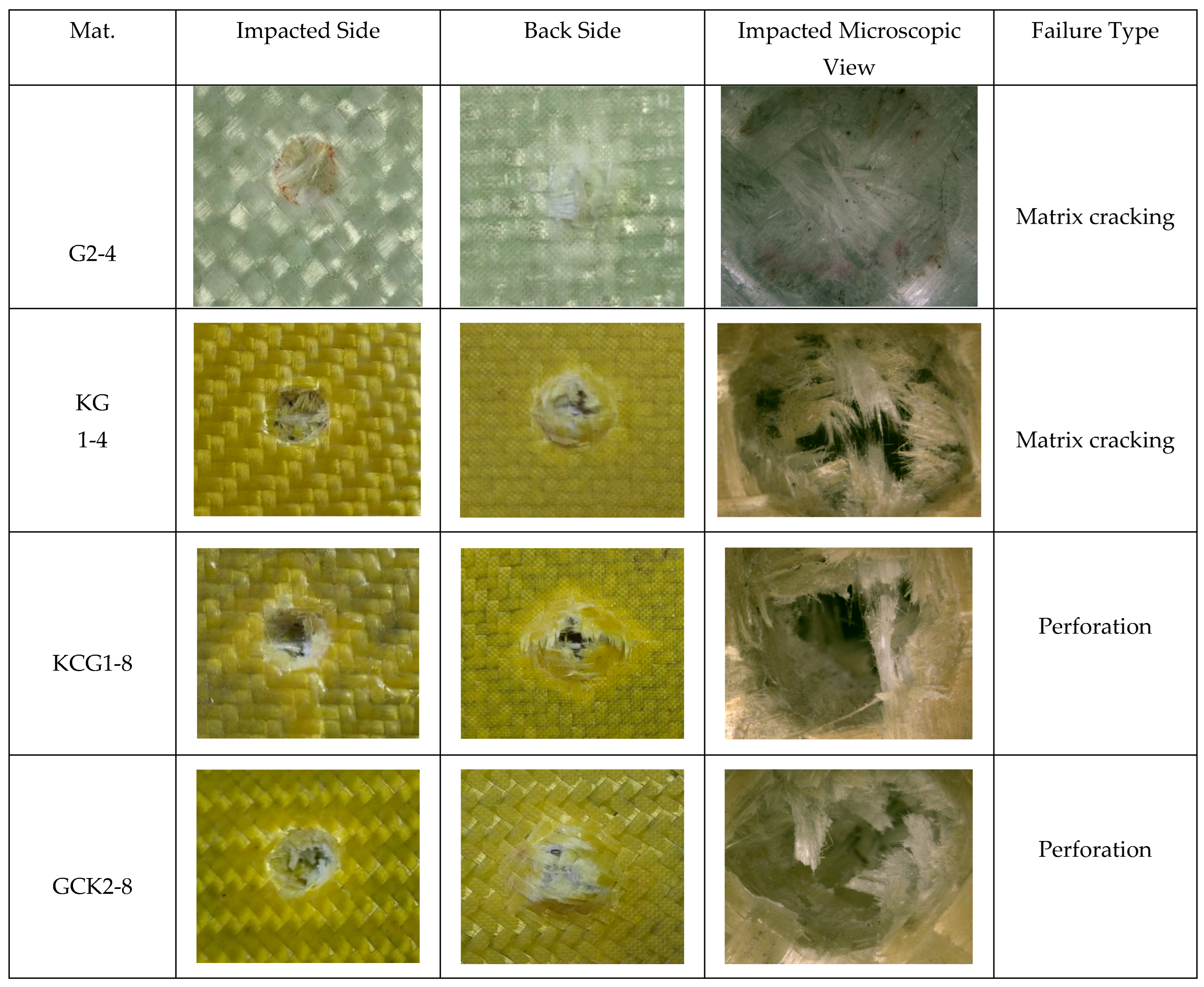
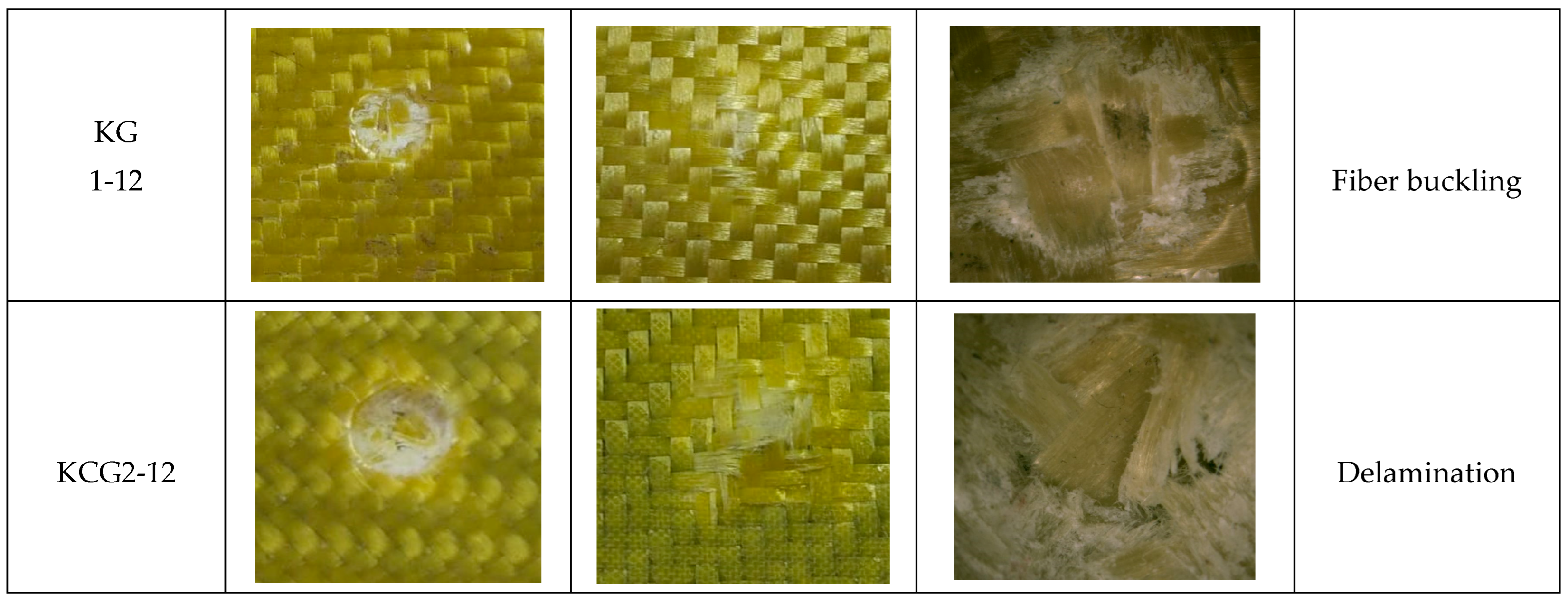
The correlation of mechanical response with failure analysis implies that the overall energy absorption depends on the post-peak damage evolution and not on the total failure duration. Analysis of the load–time and load–deflection curves shows that, although some specimens have long failure times, this is not necessarily reflected in high absorbed energy, and, hence, their correlation is weak. This is because energy dissipation in low-velocity impact is determined by the type of damage mechanisms triggered after the peak load. When the post-peak region is dominated by matrix cracking and minor delamination, there is likely to be a long-term decay of the load with a longer time scale, but these are relatively low-energy and contribute little to overall energy absorption. In contrast, specimens undergoing progressive fiber-involved damage, e.g., fiber breakage and buckling, which preserves load-carrying capacity at higher displacements, result in greater energy absorption, evidenced by a higher slope in the curve. Matrix cracking, which is initiated at an early stage due to the presence of transverse tensile and interlaminar shear stresses, fiber–matrix mismatch and localized contact stresses, primarily acts as a precursor for more severe damage rather than a dominant energy-absorbing mechanism. Therefore, the nature and the progression of post-peak damage, not the duration of failure, determine the impact performance of mono, bi-, and tri-hybrid composite laminates. This is evidenced by the high-energy absorbers (e.g., KG and K) having a substantial time duration from maximum load to failure, during which these progressive mechanisms operate. Conversely, a sample such as GCK, which failed primarily via perforation, had a very short post-peak phase and absorbed the least energy, despite potentially having a comparable total failure time. The analysis confirms that increasing the number of plies enhances both peak force and maximum displacement, with the extent of increase dependent on laminate thickness [25]. This thickness effect is visible in the escalating peak loads in Figure 5a–f, and is supported by the post-impact analysis in Figure 7, which verifies that damage area and volume increase with impact energy [6,36], where the main failure is actually identified matrix cracking (17 occurrences), which is often preceded by fiber breakage [4], beside delamination (13 occurrences) and peroration (12 occurrences), though different studies identified delamination [35], suggesting that interfacial failure and complete penetration are common subsequent or competing failure paths. In contrast, fiber-dominated failures, such as fiber breakage (7) and fiber buckling (5), were less frequent, highlighting that the fiber architectures often suppressed complete fiber fracture.

3.2. Effects of Material Composition on Average Peak Load and Total Energy

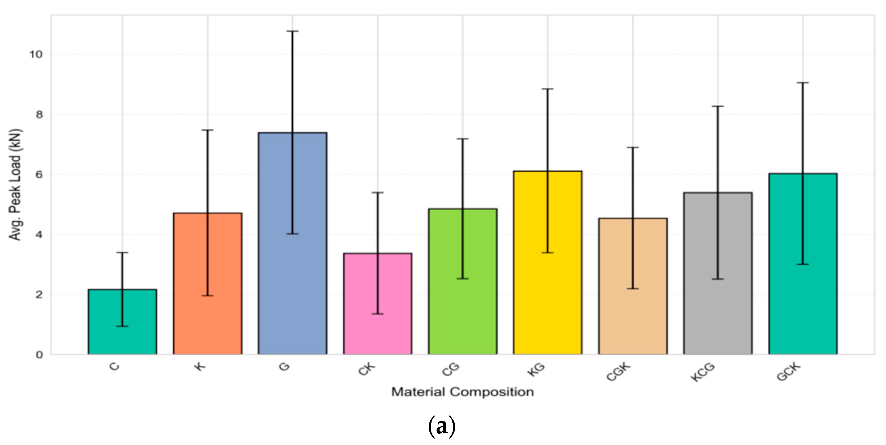
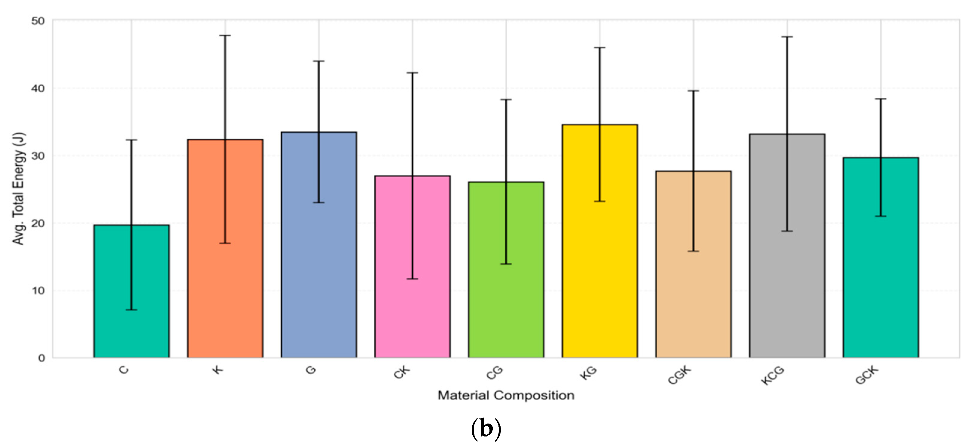
The low-velocity impact performance of composite laminates of four-, eight-, and 12-ply configurations revealed consistent trends across different constituents of materials, which are expressed in Figure 8a,b. Here, glass fiber-dominated composites consistently achieved the highest peak loads (e.g., G2-12: 12.04 kN; G1-8: 8.21 kN), owing to the high stiffness and strength of glass fibers, which provide superior resistance to initial penetration. However, this often comes at the expense of brittle failure mechanisms, resulting in lower-than-required energy absorption (e.g., G2-12: 41.78 J) due to limited plastic deformation and catastrophic fracture propagation. Conversely, Kevlar-dominated composites exhibited lower peak loads (e.g., K1-12: 7.84 kN) but consistently maximized total energy absorption across all thicknesses (e.g., K1-8: 38.33 J; K1-12: 46.80 J) [13]. The remarkable performance is due to Kevlar’s remarkable ductility, which engenders fiber fibrillation and impacts delamination and large deformations, leading to dissipation of impact energy over a wider volume. Kevlar retained a high impact energy absorption performance, while carbon fiber composites performed poorly and had peak load and energy values lower than those of any other tested material (e.g., C2-4: 0.91 kN; 7.14 J) due to their extreme brittleness and paucity of damage tolerance.
The advanced hybrid composites incorporated both strength and energy absorption capability. The carbon–Kevlar hybrids (CK series) showed a significant improvement in energy absorption (for instance, CK2-12: 43.01 J and C2-12: 26.63 J) in comparison with pure carbon [13], which is attributable to the Kevlar face layers, which improved impact resistance and lowered the stiffness [43]. The Kevlar–glass (KG) hybrids showed a good compromise between high peak loads and energy dissipation (KG1-12: 8.08 kN; 47.28 J). The tri-hybrids dominated by Kevlar, the KCG series, exhibited the best results, where KCG2-12 recorded 9.12 kN and 47.25 J [13], owing to the combination of the ductility of Kevlar and the strength of glass and carbon. The GCK laminates, such as GCK2-12 (9.90 kN), also gained stiffness, but lacked energy absorption capability (31.77–36.40 J), which is in accordance with other results, which showed that the back surface of S2-glass improved the impact response [2]. Although the tri-hybrid systems showed greater deformation and delayed failure, higher brittleness limited the rate of plastic energy dissipation [44].

3.3. Effects of Fiber Orientation on Average Peak Load and Total Energy

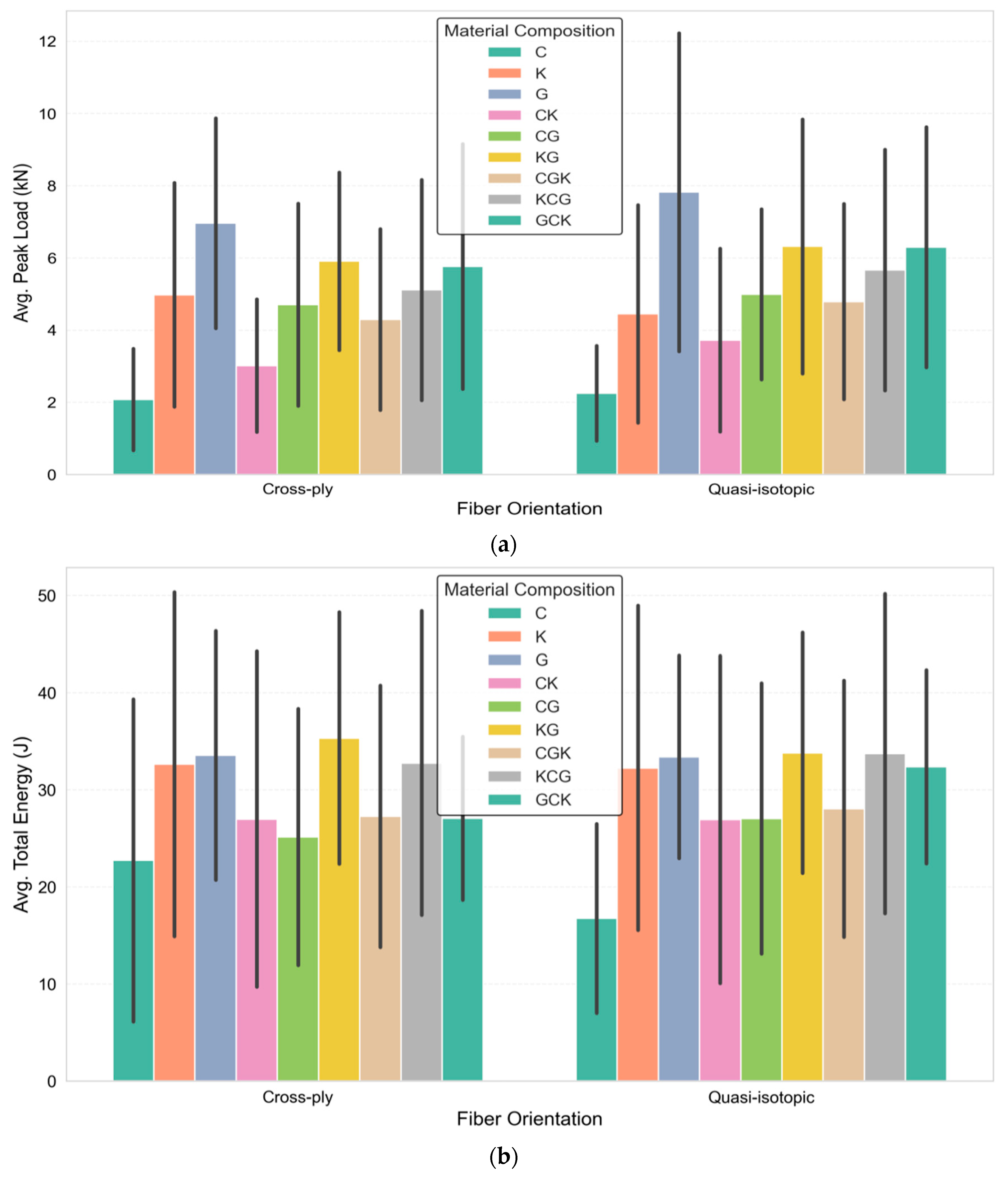
The fiber orientation, in particular, the selection of the cross-ply and quasi-isotropic orientations, has an important effect on the impact performance of composite laminates [22,45], as shown in Figure 9a,b, modulating both the average peak load and average total energy absorption by contributing through different damage initiation and propagation mechanisms. The cross-ply laminates, as per the orientation of [0/90], generally had better peak loads for most material systems, as the aligned fibers in the laminates provided resistance to impact in the principal directions to a maximum. For example, in the pure glass composites, the peak loading was found to be 9.03 kN in cross-ply G1-12 vs. 12.04 kN for quasi-isotropic G2-12, although this is an exception that shows quasi-isotropic orientations sometimes do result in higher fiber alignment for certain loading cases. Meanwhile, as shown in Figure 9b, quasi-isotropic laminates often had superior total energy absorption because the multiple directions of the fiber orientation favored more distributed damage, which includes complex delamination patterns and wider energy dissipation. This is noticeable in composites based on Kevlar, such as quasi-isotropic ligament (K2-12) with 45.54 J vs 46.80 J for cross-ply Kevlar CS (K1-12), as well as in the mix of Kevlar (KCG2-12, quasi-isotropic) with 47.25 J vs 43.96 J for Kevlar CS (KCG1-12), as in the case of Kevlar–basalt hybrid [14]. In keeping with that point, the data in the figure, across fiber orientations, present a visual reinforcement of the frequently higher-energy absorption bars for quasi-isotropic materials, especially for ductile systems, such as Kevlar and its hybrids, where the orientation allows for more progressive failure. However, brittle materials such as carbons display less pronounced benefits due to their quasi-isotropic nature, as their failure is still localized regardless of the material orientation [8]. The GCK series is, again, an example of how this interaction is sometimes subtle: GCK1-4 (cross-ply) had more energy (17.36 J) than GCK2-4 (quasi-isotropic, 21.02 J) at four-ply, but the behavior was opposite at 12-ply, with GCK2-12 (quasi-isotropic) having 36.40 J, compared with 31.77 J for GCK1-12 (cross-ply), suggesting that quasi-isotropy facilitates better distribution of damages in thicker sections.

3.4. Effects of No. of Ply on Average Peak Load and Total Energy

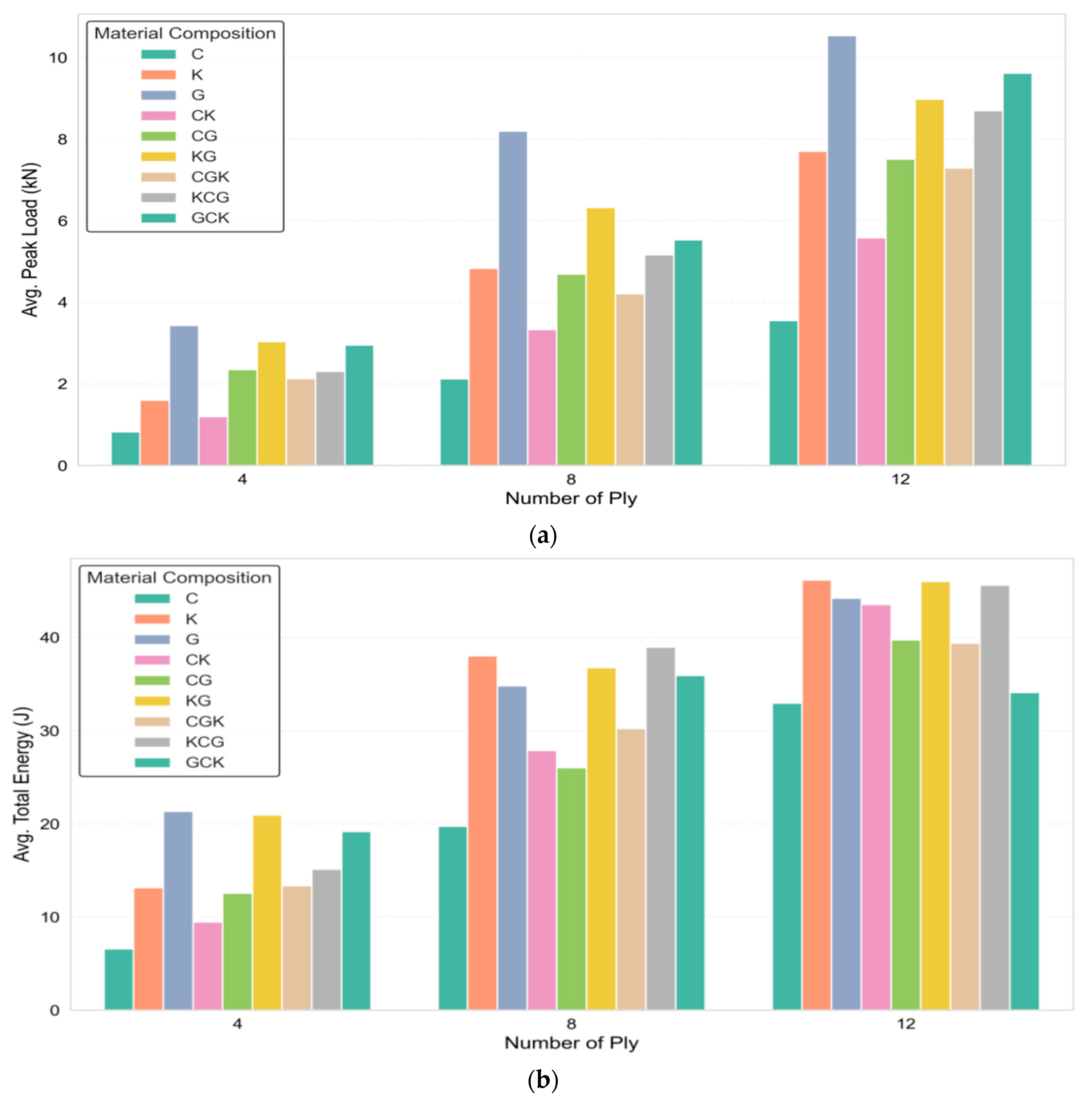
The number of layers of a laminate produces a certain thickness and has a direct impact on the stiffness, failure modes, and energy dissipation of the laminate, thus changing the impact response of the laminate [46]. This is shown in Figure 10a,b. Adding four more plies, from 4 to 12, increased the peak load on all the systems. This is evident for the carbon system, which increased from 0.82 kN to 3.55 kN; for the glass system, which increased from 3.43 kN to 10.54 kN; and for Kevlar, which increased from 1.60 kN to 7.70 kN. Also, the energy was absorbed and was notably increased, which, for the Kevlar system, was from 13.13 J to 46.17 J, which was due to increased delamination and fiber pull. The Kevlar–glass (KG) and KCG hybrids also showed a balance of energy and load. The KCG2-12 hybrid reached 47.25 J [23]. The GCK laminate was GCK2-12, showing a peak load of 9.90 kN, but it had the least energy in a dissipation state due to brittle failure. It can be generalized that having more plies is beneficial to hybrid systems, as it enhances the peak load and energy absorbed for the system as a whole [29].

4. Conclusions

The investigation in this thesis focused on the damage behavior and the low-velocity impact (LVI) performance of fiber-reinforced epoxy composites. As a result of a regimented testing program, some conclusions were drawn. For example, the impact response was predominantly determined by the fiber used. In the cross-ply glass laminate, the glass fibers yielded the maximum peak load (3.24 kN) and energy absorbed (21.69 J), albeit exhibiting brittle failure. The same trend was observed in thicker laminates, particularly the glass-dominated carbon–Kevlar tri-hybrid, where a peak load of 5.67 kN and energy absorption of 39.70 J were noted. In comparison, Kevlar-dominated composites achieved the maximum energy absorption due to ductile failure as the Kevlar–glass bi-hybrid revealed a peak load of 8.08 kN and an energy absorption of 47.28 kJ, which was close to the Kevlar-dominated carbon–glass tri-hybrid composite. Additionally, it was critical to determine the laminate impact response, impact energy absorption, and peak load response during impact as a function of laminate thickness, both in terms of ply numbers and physical thickness. Increasing the thickness/number of plies of the laminate enhanced the impact peak energy absorption as well as the impact energy absorption. Overall, cross-ply laminates provided higher total energy absorption and enhanced impact peak energy absorption than quasi-isotropic laminates. This research provides a foundation that can be used in the design of impact-resistant composite materials. The data resulting from this research provide much-needed experimental data regarding fiber composition, hybridization approaches, lay-up angles, and laminate thickness as a composite set, determining the low-velocity impact response. Optimally, these materials can be used in the aerospace, automotive and defense industries, where energy absorption along with damage tolerance are critical.

Author Contributions

Conceptualization, M.M.R. and A.E.I.; methodology, M.M.R.; software, M.M.R.; validation, A.E.I., M.F.R., A.H.A.R., T.K., O.S.A., T.A.S.; formal analysis, M.M.R.; investigation, M.M.R.; resources, A.E.I.; data curation, M.M.R.; writing—original draft preparation, M.M.R., T.K.; writing—review and editing, A.E.I., M.F.R., A.H.A.R., O.S.A., and T.A.S.; visualization, M.M.R.; supervision, A.E.I., M.F.R. and A.H.A.R.; project administration, A.E.I.; funding acquisition, A.E.I., T.K., O.S.A., and T.A.S. All authors have read and agreed to the published version of this manuscript.

Funding

This research was funded by the Ministry of Higher Education (MOHE), Malaysia through the Fundamental Research Grant Scheme (FRGS/1/2023/TK04/UTHM/02/1).

Data Availability Statement

The original contributions presented in this study are included in this article. Data will be made available upon request to the corresponding author.

Acknowledgments

This research was supported by the Ministry of Higher Education (MOHE), Malaysia. The authors would also like to acknowledge the support of Prince Sultan University, Riyadh, for paying the Article Processing Charge (APC) of this publication.

Conflicts of Interest

The authors declare no conflicts of interest.

References

  1. Zhang, Z.Y.; Richardson, M.O.W. Low velocity impact induced damage evaluation and its effect on the residual flexural properties of pultruded GRP composites. Compos. Struct. 2007, 81, 195–201. [Google Scholar] [CrossRef] [Scilit]
  2. Hosur, M.V.; Adbullah, M.; Jeelani, S. Studies on the low-velocity impact response of woven hybrid composites. Compos. Struct. 2005, 67, 253–262. [Google Scholar] [CrossRef] [Scilit]
  3. Hasan-nezhad, H.; Yazdani, M.; Jeddi, M. High- and low-velocity impact experiments on treated STF/3D glass fabrics. Thin-Walled Struct. 2022, 171, 108720. [Google Scholar] [CrossRef] [Scilit]
  4. Fakhreddini-Najafabadi, S.; Torabi, M.; Taheri-Behrooz, F. An experimental investigation on the low-velocity impact performance of the CFRP filled with nanoclay. Aerosp. Sci. Technol. 2021, 116, 106858. [Google Scholar] [CrossRef] [Scilit]
  5. Goodarz, M.; Bahrami, S.H.; Sadighi, M.; Saber-Samandari, S. Low-velocity impact performance of nanofiber-interlayered aramid/epoxy nanocomposites. Compos. Part B Eng. 2019, 173, 106975. [Google Scholar] [CrossRef] [Scilit]
  6. Majid, D.L.; Jamal, Q.M.; Manan, N.H. Low-velocity Impact Performance of Glass Fiber, Kenaf Fiber, and Hybrid Glass/Kenaf Fiber Reinforced Epoxy Composite Laminates. BioResources 2018, 13, 8839–8852. [Google Scholar] [CrossRef] [Scilit]
  7. Shishevan, F.A.; Akbulut, H.; Mohtadi-Bonab, M.A. Low Velocity Impact Behavior of Basalt Fiber-Reinforced Polymer Composites. J. Mater. Eng. Perform. 2017, 26, 2890–2900. [Google Scholar] [CrossRef] [Scilit]
  8. Ying, S.; Mengyun, T.; Zhijun, R.; Baohui, S.; Li, C. An experimental investigation on the low-velocity impact response of carbon-aramid/epoxy hybrid composite laminates. J. Reinf. Plast. Compos. 2017, 36, 422–434. [Google Scholar] [CrossRef] [Scilit]
  9. Ge, X.; Zhang, P.; Zhao, F.; Liu, M.; Liu, J.; Cheng, Y. Experimental and numerical investigations on the dynamic response of woven carbon fiber reinforced thick composite laminates under low-velocity impact. Compos. Struct. 2022, 279, 114792. [Google Scholar] [CrossRef] [Scilit]
  10. Zhang, C.; Huang, J.; Li, X.; Zhang, C. Numerical Study of the Damage Behavior of Carbon Fiber/Glass Fiber Hybrid Composite Laminates under Low-velocity Impact. Fibers Polym. 2020, 21, 2873–2887. [Google Scholar] [CrossRef] [Scilit]
  11. Barouni, A.K.; Dhakal, H.N. Damage investigation and assessment due to low-velocity impact on flax/glass hybrid composite plates. Compos. Struct. 2019, 226, 111224. [Google Scholar] [CrossRef] [Scilit]
  12. Liu, H.; Liu, J.; Ding, Y.; Zheng, J.; Kong, X.; Zhou, J.; Harper, L.; Blackman, B.R.K.; Kinloch, A.J.; Dear, J.P. The behaviour of thermoplastic and thermoset carbon fibre composites subjected to low-velocity and high-velocity impact. J. Mater. Sci. 2020, 55, 15741–15768. [Google Scholar] [CrossRef] [Scilit]
  13. Stephen, C.; Thekkuden, D.T.; Mourad, A.H.I.; Shivamurthy, B.; Selvam, R.; Behara, S.R. Prediction of impact performance of fiber reinforced polymer composites using finite element analysis and artificial neural network. J. Braz. Soc. Mech. Sci. Eng. 2022, 44. [Google Scholar] [CrossRef] [Scilit]
  14. Bandaru, A.K.; Patel, S.; Ahmad, S.; Bhatnagar, N. An experimental and numerical investigation on the low velocity impact response of thermoplastic hybrid composites. J. Compos. Mater. 2018, 52, 877–889. [Google Scholar] [CrossRef] [Scilit]
  15. Fazita, M.R.N.; Khalil, H.P.S.A.; Izzati, A.N.A.; Rizal, S. Effects of Strain Rate on Failure Mechanisms and Energy Absorption in Polymer Composites; Elsevier Ltd.: Amsterdam, The Netherlands, 2018. [Google Scholar] [CrossRef] [Scilit]
  16. Dehkordi, M.T.; Nosraty, H.; Shokrieh, M.M.; Minak, G.; Ghelli, D. Low velocity impact properties of intra-ply hybrid composites based on basalt and nylon woven fabrics. Mater. Des. 2010, 31, 3835–3844. [Google Scholar] [CrossRef] [Scilit]
  17. Wang, A.; Wang, X.; Xian, G. Mechanical, low-velocity impact, and hydrothermal aging properties of flax/carbon hybrid composite plates. Polym. Test. 2020, 90, 106759. [Google Scholar] [CrossRef] [Scilit]
  18. Seltzer, R.; González, C.; Muñoz, R.; Llorca, J.; Blanco-Varela, T. X-ray microtomography analysis of the damage micromechanisms in 3D woven composites under low-velocity impact. Compos. Part A Appl. Sci. Manuf. 2013, 45, 49–60. [Google Scholar] [CrossRef] [Scilit]
  19. Zhang, D.; Sun, Y.; Chen, L.; Pan, N. A comparative study on low-velocity impact response of fabric composite laminates. Mater. Des. 2013, 50, 750–756. [Google Scholar] [CrossRef] [Scilit]
  20. Baucom, J.N.; Zikry, M.A. Low-velocity impact damage progression in woven E-glass composite systems. Compos. Part A Appl. Sci. Manuf. 2005, 36, 658–664. [Google Scholar] [CrossRef] [Scilit]
  21. Dhakal, H.N.; Zhang, Z.Y.; Richardson, M.O.W.; Errajhi, O.A.Z. The low velocity impact response of non-woven hemp fibre reinforced unsaturated polyester composites. Compos. Struct. 2007, 81, 559–567. [Google Scholar] [CrossRef] [Scilit]
  22. Wang, B.; Zhong, S.; Lee, T.L.; Fancey, K.S.; Mi, J. Non-destructive testing and evaluation of composite materials/structures: A state-of-the-art review. Adv. Mech. Eng. 2020, 12, 1687814020913761. [Google Scholar] [CrossRef] [Scilit]
  23. Bhudolia, S.K.; Joshi, S.C. Low-velocity impact response of carbon fibre composites with novel liquid Methylmethacrylate thermoplastic matrix. Compos. Struct. 2018, 203, 696–708. [Google Scholar] [CrossRef] [Scilit]
  24. Bensadoun, F.; Depuydt, D.; Baets, J.; Verpoest, I.; van Vuure, A.W. Low velocity impact properties of flax composites. Compos. Struct. 2017, 176, 933–944. [Google Scholar] [CrossRef] [Scilit]
  25. Zhou, J.; Liu, B.; Wang, S. Finite element analysis on impact response and damage mechanism of composite laminates under single and repeated low-velocity impact. Aerosp. Sci. Technol. 2022, 129, 107810. [Google Scholar] [CrossRef] [Scilit]
  26. Li, Y.Y.; Lyu, Z.Q.; Wang, P.; Wang, Y.L.; Chen, T.; Zhang, Y. Finite Element Analyses on Low-velocity Impact Responses of Three-dimensional Braided Composites. Fibers Polym. 2021, 22, 2296–2305. [Google Scholar] [CrossRef] [Scilit]
  27. Falcó, O.; Lopes, C.S.; Sommer, D.E.; Thomson, D.; Ávila, R.L.; Tijs, B.H.A.H. Experimental analysis and simulation of low-velocity impact damage of composite laminates. Compos. Struct. 2022, 287, 115278. [Google Scholar] [CrossRef] [Scilit]
  28. Yang, L.; Yan, Y.; Kuang, N. Experimental and numerical investigation of aramid fibre reinforced laminates subjected to low velocity impact. Polym. Test. 2013, 32, 1163–1173. [Google Scholar] [CrossRef] [Scilit]
  29. Li, X.; Liang, B.; Liu, P.; Cheng, H.; Cao, S.; Zhang, K. Experimental and numerical analysis of low-velocity impact damage of CFRP laminates with rubber protective layer. Compos. Struct. 2022, 300, 116152. [Google Scholar] [CrossRef] [Scilit]
  30. Han, G.; Guan, Z.; Li, X.; Du, S. Failure analysis of carbon fiber reinforced composite subjected to low velocity impact and compression after impact. J. Reinf. Plast. Compos. 2016, 35, 727–746. [Google Scholar] [CrossRef] [Scilit]
  31. Chen, Y.; Zeng, X.; Deng, Y.; Wei, G. Investigation on manufacturing and low-velocity impact performance of all-composite sandwich structure with S-type foldcore. Compos. Struct. 2022, 290, 115539. [Google Scholar] [CrossRef] [Scilit]
  32. Stephen, C.; Mourad, A.H.I.; Shivamurthy, B.; Selvam, R. Energy absorption and damage assessment of non-hybrid and hybrid fabric epoxy composite laminates: Experimental and numerical study. J. Mater. Res. Technol. 2021, 14, 3080–3091. [Google Scholar] [CrossRef] [Scilit]
  33. Liao, B.B.; Liu, P.F. Finite element analysis of dynamic progressive failure properties of GLARE hybrid laminates under low-velocity impact. J. Compos. Mater. 2018, 52, 1317–1330. [Google Scholar] [CrossRef] [Scilit]
  34. Tita, V.; de Carvalho, J.; Vandepitte, D. Failure analysis of low velocity impact on thin composite laminates: Experimental and numerical approaches. Compos. Struct. 2008, 83, 413–428. [Google Scholar] [CrossRef] [Scilit]
  35. Sahu, Y.K.; Vishwas, S.; Singh, S. Review of low velocity impact on reinforced fiber based hybrid composite. J. Phys. Conf. Ser. 2022, 19, 032038. [Google Scholar]
  36. Sun, M.; Zhang, D.; Qian, K. Visualization and quantification of low-velocity impact damage of three-dimensional braided CFRP composites by micro-computed tomography. Heliyon 2022, 8, e12110. [Google Scholar] [CrossRef] [Scilit] [PubMed]
  37. Guo, S.; Li, X.; Liu, T.; Bu, G.; Bai, J. Parametric Study on Low-Velocity Impact (LVI) Damage and Compression after Impact (CAI) Strength of Composite Laminates. Polymers 2022, 14, 5200. [Google Scholar] [CrossRef] [Scilit]
  38. Li, X.; Liu, P.; Cheng, H.; Liu, C.; Zhu, Y.; Zhang, K. Experimental and numerical analysis of low-velocity impact damage of CFRP laminates with negative Poisson ratio (NPR) rubber protective layer. Thin-Walled Struct. 2023, 191, 111066. [Google Scholar] [CrossRef] [Scilit]
  39. Sun, M.; Liu, X.; Zhang, D.; Sun, J.; Qian, K. Effects of structural defects on low-velocity impact damage mechanisms of three-dimensional braided composites based on X-ray micro-computed tomography. Polym. Test. 2021, 104, 107403. [Google Scholar] [CrossRef] [Scilit]
  40. Bandaru, A.K.; Chavan, V.V.; Ahmad, S.; Alagirusamy, R.; Bhatnagar, N. Low velocity impact response of 2D and 3D Kevlar/polypropylene composites. Int. J. Impact Eng. 2016, 93, 136–143. [Google Scholar] [CrossRef] [Scilit]
  41. Ravandi, M.; Teo, W.S.; Tran, L.Q.N.; Yong, M.S.; Tay, T.E. Low velocity impact performance of stitched flax/epoxy composite laminates. Compos. Part B Eng. 2017, 117, 89–100. [Google Scholar] [CrossRef] [Scilit]
  42. Wang, A.; Liu, X.; Yue, Q.; Xian, G. Effect of volume ratio and hybrid mode on low-velocity impact properties of unidirectional flax/carbon fiber hybrid reinforced polymer composites. Thin-Walled Struct. 2023, 187, 110764. [Google Scholar] [CrossRef] [Scilit]
  43. Gustin, J.; Joneson, A.; Mahinfalah, M.; Stone, J. Low velocity impact of combination Kevlar/carbon fiber sandwich composites. Compos. Struct. 2005, 69, 396–406. [Google Scholar] [CrossRef] [Scilit]
  44. Chen, D.; Luo, Q.; Meng, M.; Sun, G. Low velocity impact behavior of interlayer hybrid composite laminates with carbon/glass/basalt fibres. Compos. Part B Eng. 2019, 176, 107191. [Google Scholar] [CrossRef] [Scilit]
  45. Pai, Y.; Pai, K.D.; Kini, M.V. A review on low velocity impact study of hybrid polymer composites. Mater. Today Proc. 2021, 46, 9073–9078. [Google Scholar] [CrossRef] [Scilit]
  46. Nadzri, S.N.Z.A.; Sultan, M.T.H.; Shah, A.U.M.; Safri, S.N.A.; Basri, A.A. A review on the kenaf/glass hybrid composites with limitations on mechanical and low velocity impact properties. Polymers 2020, 12, 1285. [Google Scholar] [CrossRef] [Scilit]
Figure 1. (a) Carbon, (b) Kevlar and (c) glass fabric.
Jcs 10 00230 g001
Figure 2. Connector/vacuum fitting setting and close bagging. (a) Bleeder fabric double layering, (b) vacuum connector (1st part) setting, (c) polythene sheet (top) layering and sealant tape closing, (d) hole making above 1st part of vacuum connector for air exhaustion, (e) vacuum connector (2nd part) setting, and (f) vacuum connector (2nd part) and air exhaust pipe connecting.
Jcs 10 00230 g002
Figure 4. Material characterization by optical microscope.
Jcs 10 00230 g004
Figure 5. Load versus time (left) and load versus deflection (right) plotting in (a,b) for 4 ply, (c,d) for 8 ply, and (e,f) for 12 ply.
Jcs 10 00230 g005
Figure 6. Main failure type by material composition.
Jcs 10 00230 g006
Figure 7. Impacted face and back-side images with microscopic view.
Jcs 10 00230 g007aJcs 10 00230 g007b
Figure 8. Effects of material composition on average (a) peak load and (b) total energy.
Jcs 10 00230 g008aJcs 10 00230 g008b
Figure 9. Effects of fiber orientation on average (a) peak load and (b) total energy.
Jcs 10 00230 g009
Figure 10. Effects of no. of ply on average (a) peak load and (b) total energy.
Jcs 10 00230 g010
Table 1. Technical details of carbon, Kevlar and glass fabric.
ItemsCarbonKevlarGlass
Fiber orientation0, 900, 900, 90
ColorBlackYellowWhite
Weave2 × 2 twill2 × 2 twill1 × 1 plain
FormatWovenWovenWoven
Weight (GSM)200300600
Fiber typeCarbonKevlarE-glass
Tensile strength (MPa)37583000-
Tensile modulus (GPa)231 GPa112.4-
Density (g/cm3)1.8 1.442.55
Consolidated thickness (mm)0.28 0.400.52
Table 2. Coding details of fabricated laminates.
Fiber Composition (%)Symmetric Layer OrderCode LetterPly TypeNo. of PlyCoding Example
(C = Carbon, K = Kevlar, G = Glass)
100%[C/C/C/C]s,
[K/K/K/K]s
[G/G/G/G]s
C,
K,
G
1 = Cross-ply/
2 = Quasi-isotropic
4/8/12Jcs 10 00230 i001
50% + 50%[K/C/C/K]s,
[C/G/G/C]s,
[K/G/G/K]s
CK,
CG,
KG
1 = Cross-ply/
2 = Quasi-isotropic
4/8/12Jcs 10 00230 i002
50% + 25% + 25%[K/C/G/C]s,
[K/G/C/K]s,
[K/G/G/C]s
CGK,
KCG,
GCK
1 = Cross-ply/
2 = Quasi-isotropic
4/8/12Jcs 10 00230 i003
Table 3. Details of drop weight impact test.
ParticularsDrop Weight Impact Test
StandardASTM D7136
Instrument Dynatup Drop Weight Impact Tower
Specimen dimension (mm × mm)100 × 100
Cross-head weight (Kg)6.5
Raw data acquisitionTime, load, deflection, energy, and velocity 
Consolidated
calculated data acquisition
Impact energy (J), peak load (kN), deflection at peak load (mm), deflection at failure (mm), total deflection (mm), energy to peak load (J), energy to failure (J), energy to peak load (J), total energy (J), and time to maximum load, yield and failure (ms)
Drop height (cm)19–79
Impact velocity (m/s)1.91–3.91
Table 4. Performance by main failure type.
Main Failure TypeAverage Peak Load (kN)Average Total Energy (J)
Fiber breakage6.3237.66
Fiber buckling7.5936.80
Matrix cracking5.7331.48
Delamination4.0726.11
Perforation2.8921.74
Disclaimer/Publisher’s Note: The statements, opinions and data contained in all publications are solely those of the individual author(s) and contributor(s) and not of MDPI and/or the editor(s). MDPI and/or the editor(s) disclaim responsibility for any injury to people or property resulting from any ideas, methods, instructions or products referred to in the content.