Article

Design Guide for Hybrid-Additive Manufacturing of Inconel 718 Combining PBF-LB/M and In Situ High-Speed Milling

1
Applied Laser and Photonics Group, University of Applied Sciences Aschaffenburg, 63741 Aschaffenburg, Germany
2
Applied Laser Technologies, Ruhr University Bochum, 44801 Bochum, Germany
*
Author to whom correspondence should be addressed.
J. Manuf. Mater. Process. 2025, 9(3), 88; https://doi.org/10.3390/jmmp9030088
Submission received: 29 January 2025 / Revised: 24 February 2025 / Accepted: 4 March 2025 / Published: 10 March 2025
(This article belongs to the Special Issue Advances in Powder Bed Fusion Technologies)

Abstract

As the correlation between design rules and process limitations is of the upmost importance for the full exploitation of any manufacturing technology, we report a design guide for hybrid-additive manufacturing of Inconel 718. Basic limitations need to be evaluated for this particular hybrid approach that combines laser powder bed fusion (PBF-LB/M) and in situ high-speed milling. Fundamental geometric limitations are examined with regard to the minimum feasible wall thickness, cylinders, overhanging structures, and chamfers. Furthermore, geometrical restrictions due to the integrated three-axis milling process with respect to inclinations, inner angles, notches, and boreholes are investigated. From these findings, we derive design guidelines for a reliable build process using this hybrid manufacturing. Additionally, a design guideline for the hybrid-additive manufacturing approach is presented, depicting a step-to-step guide for the adjustment of constructions. To demonstrate this, a powder nozzle for a direct energy deposition (DED-LB/M) process is redesigned following the previously defined guidelines. This redesign encompasses analysis of the existing component and identification of problematic areas such as flat angles, leading to a new construction that is suitable for a hybrid-additive manufacturing approach.

1. Introduction

Additive manufacturing continues to gain attractiveness in industrial applications. The powder bed fusion of metals with laser beams (commonly abbreviated as PBF-LB/M) is especially common in the manufacturing of high-performance metallic components in different fields of applications [1]. Due to the high freedom of design and the multiplicity of available materials, lightweight components—including complex structures or applications of aerospace and aeronautics—are manufactured using PBF-LB/M [2,3]. Nevertheless, while these advantages unlock new ways of manufacturing, the application of this process is limited by its disadvantages. These include inferior geometrical accuracy and high surface roughness, both developing as a consequence of the laser melting process and the layer-wise building approach [4,5]. Due to this, a time-consuming post-processing method is necessary to enable high-precision components. In order to mitigate the disadvantages, hybrid milling processes are designed, combining additive and subtractive processes, integrating the required post-processing into the building process [6,7]. While different additive manufacturing processes—such as electron-beam melting [8], two-photon polymerization [9], direct energy deposition (DED-LB/M), and metal arc welding—have been combined with mechanical turning or milling [10,11] and laser machining [12], another promising hybrid approach has recently evolved, combining PBF-LB/M with an integrated high-speed milling system.
As conventional milling processes exhibit a superior geometrical accuracy and a smooth surface finish [13], the disadvantages of the PBF-LB/M process can be excluded while still using its advantages [14,15]. The additional post-processing is directly integrated by the in situ milling process, leading to a more flexible operation during additive manufacturing, milling inner contours and undercuts that are probably inaccessible after the build process.
However, due to the various materials available for PBF-LB/M, different challenges arise regarding the additive manufacturing process as well as the high-speed milling process. First, the process parameters of the PBF-LB/M-process have to be determined for every material, as various studies have dealt with fundamental parameter variation [16,17,18,19]. Due to physical characteristics such as thermal conductivity, differences in shape accuracy and geometrical deviations arise between the various materials [20].
Furthermore, the milling process exhibits different peculiarities given by integration into the PBF-LB/M-process. As the milling process alternates with the additive manufacturing process, different challenges arise after the thermal impact, given by the PBF-LB/M- and the milling process and reinforced by the powder bed. Due to this, the process parameters have to be evaluated for a hybrid approach, just like for the PBF-LB/M-process. Geometrical accuracy as well as design guidelines have to be determined, especially with regard to thermal mechanisms.
As IN718 is a high-strength, precipitation-hardening, Ni-based superalloy, the machining is difficult in comparison to other materials, e.g., maraging steel [21]. Elevated wear characteristics lead to reduced productivity rates as well as to inferior surface quality [22,23]. On the other hand, it is well suited for high-temperature and performance components, seeing use in aviation and aerospace applications [24].
Against this multisided background, we report on a study investigating the geometrical design limits of the hybrid-additive manufacturing approach, combining PBF-LB/M and high-speed milling. The manufacturabilities of basic elements like thin walls and cylinders are examined and compared with the sole PBF-LB/M process. Furthermore, the limitations of the hybrid approach regarding inclinations, inner angles, clearance widths, and boreholes are determined. Construction boundaries and geometrical accuracy are evaluated, highlighting the importance of reliable build processes. In concluding, the gained knowledge is applied to a redesign of a powder nozzle for the DED-LB/M process. In this exemplifying stepwise design-guide, the existing component is examined with respect to problem areas that arise due to the three-axis milling system. This is followed by a redesign of the concerning points. With that, the advantages of the hybrid-additive manufacturing approach can be fully exploited, as the procedure can be applied to a range of components.

2. Materials and Methods

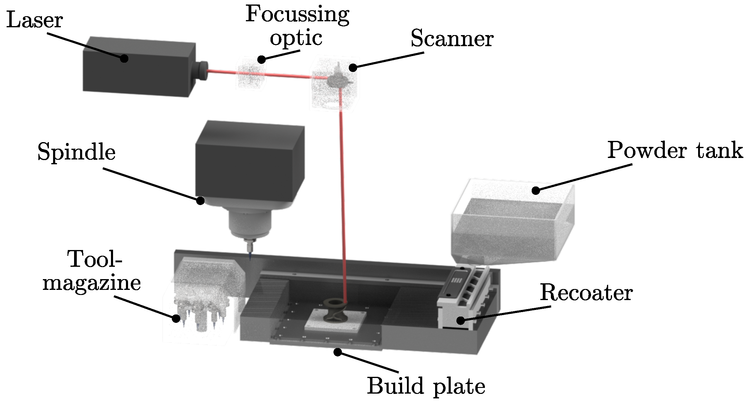
2.1. Machine and Process

For the investigation of hybrid-additive manufactured specimens with respect to their geometrical and shape accuracy, a Lumex Avance-25 (Matsuura, Wiesbaden, Germany) was employed. It combines a conventional PBF-LB/M as an additive process with high-speed milling as a subtractive process, constituting a unique hybrid-additive manufacturing approach. The high-speed milling process is, as schematically illustrated in Figure 1, directly integrated in a PBF-LB/M-machine which itself does not differ from industrial standards.
For the PBF-LB/M-process, a Yb-fiber laser with an operating wavelength of λ = 1070 nm is used with a maximum power P L = 500 W, and a nominal spot size of d spot = 200 μm at focus position. The used process parameters, derived from previously published work by the authors [26,27], are shown in Table 1, while the layer height is set to d layer = 50 μm and the maximum build volume is V = 250 × 250 × 185 mm3 in width, depth, and height, respectively. The build plate is kept at a temperature of ϑ = 50 °C to avoid residual stress and curling during the PBF-LB/M-process, and the process is conducted under nitrogen atmosphere.
The integrated high-speed milling process operates with a three-axis milling system with a high-speed spindle, having a maximum rotational velocity of n = 45,000 1/min and a maximum torque of M = 1.31 Nm. The milling process does, again, not differ from industrial standard, with the spindle accessing a twentyfold tool magazine, thus enabling a tool change during machining. As the milling process is directly integrated in the PBF-LB/M-process, the usage of cooling lubricant is not possible, and the dry milling process takes place within the powder bed as well as the elevated temperature reinforce wear mechanisms [28,29].
The procedure of the hybrid-additive manufacturing is divided into four repeating steps, as depicted in Figure 2. The PBF-LB/M-process is interrupted after ten layers for the milling process. A material allowance of a t = 250 μm is added on the outer surfaces of the constructed geometry, becoming removed gradually by a series of milling processes. At first, a roughing process takes place, detaching a 1 = 110 μm of the material allowance (cf. Figure 2b, step 2). Analogous to the following semi-finishing step, the roughing process works from the top to the bottom, deburring the surface texture and clearing irregularities. The semi-finishing process removes another a 2 = 110 μm of the allowance. Finally, the finishing process dissipates the remaining a 3 = 30 μm, ensuring a high surface quality as well as high geometrical accuracy. To avoid residual stress, the finishing cutter starts underneath the last built layers, working upwards and sparing several layers of the material allowance for the next process cycle (cf. Figure 2a,d) [30,31]. To analyze design constraints for the hybrid-additive manufacturing approach, previously determined process parameters are used, given by Table 2.
As several studies have reported before, the geometrical and shape accuracy as well as the surface roughness of inclined structures are detracted by the staircase effect, arising due to the layer-wise manufacturing of the PBF-LB/M-process [32,33,34]. As illustrated in Figure 3a,b, the hybrid approach can minimize the staircase effect with the directly integrated post-processing. Moreover, the three-axis milling system enables the machining of inclined, down-facing surfaces with the usage of T-slot milling cutters (cf. Figure 3c,d. With that, a complete post-processing of inclinations from an angle of α = 52° is possible, determined by the geometry of the T-slot milling cutter and the standard parameters. As support structures are conventionally used up to an inclination of α = 25° to 40°, a non-millable area arises between the supported parts and the completely post-processed parts of the build components [20,35,36].

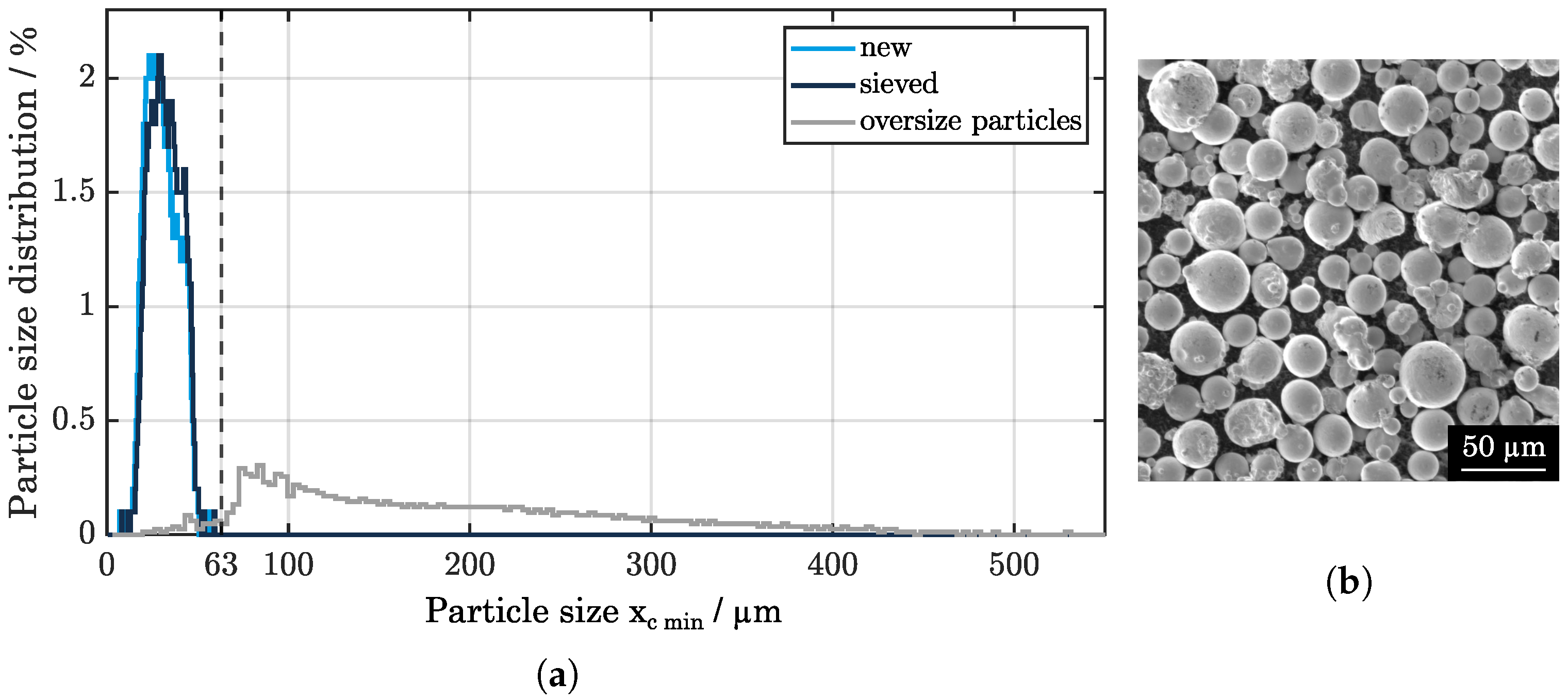
2.2. Powder Characterization

Throughout the study, Inconel 718 powder (Heraeus, Hanau, Germany) is used, a nickel superalloy with high strength and temperature resistance as well as good mechanical properties. Due to its hardness, increasing with heat-treatment processes, IN 718 components are frequently used for aerospace and high-performance applications. The chemical composition for the used powder material is listed in Table 3.

2.3. Experimental Setup

A comparison is made between the hybrid-additive manufacturing process and the sole PBF-LB/M-process. Initially, specimens are built with the PBF-LB/M-process, evaluating its geometrical dimensions. Afterwards, the manufacturability of the structures is investigated using high-speed milling additionally. The specimens of both techniques are compared, geometrical deviations are determined, and design guidelines are derived.
For the evaluation of shape accuracy and geometrical deviations, a 3D-Scan is conducted, capturing the structures with a stripe line projection (AtosCore, GOM, Braunschweig, Germany). Due to a comparison of the constructed and physically realized geometry, the shape accuracy can be inspected, and geometrical deviations can be measured quantitatively.
For quantitative examination of smaller structures as well as for higher aspect ratios, a VR-3000 macroscope (Keyence, Neu-Isenburg, Germany) is used, operating with stripe line projection as well. Accurate measurements are executed, using a maximum magnification of 20 times.
For closer inspection, especially for smaller notches, a digital microscope DVM6 (Leica, Wetzlar, Germany) with a PlanAPO FOV 12.55 is used. Employing the z-stack function, several images of the specimens are captured, generating a good depth of field.
Particle size distribution of the used powder is measured, using a particle analyzer (Camsizer X2, Microtrac Retsch, Haan, Germany), based on dynamic image analysis, according to ISO 13322-2 [38].

3. Results and Discussion

3.1. Powder Distribution

For the PBF-LB/M-process, the powder distribution has to be consistent throughout the study, as the mechanical and dimensional properties of the components should be guaranteed. Due to different thermal and physical mechanisms, mechanical deformation and deterioration occur, necessitating a sieving of the used powder material. In addition, as the high-speed milling process is directly integrated within the PBF-LB/M-process, abrasive material from the milling cutter as well as chips of the milling process have to be removed additionally to avoid negative effects for the PBF-LB/M.
As shown in Figure 4a, the sieved powder and the pristine powder show a similar distribution, peaking at x c min = 30 μm, as specified. Precisely, the percentile values of the new powder show d 10 = 16.6 μm, d 50 = 28.6 μm, and d 90 = 42.2 μm, while the sieved powder does only differ marginally, with d 10 = 20.8 μm, d 50 = 31.5 μm, and d 90 = 43.4 μm. In addition, the morphology shows only small adhered particles, as revealed in Figure 4b. The oversize particles, originating from the milling process and the occurring abrasion, are separated from the powder particles reliably by sieving, adhering only a small number of particles below the mesh size of b = 63 μm. Due to the steady sieving, a disadvantage by virtue of the recycling is excluded, and the flowability is maintained, thus ensuring a consistent PBF-LB/M-process.

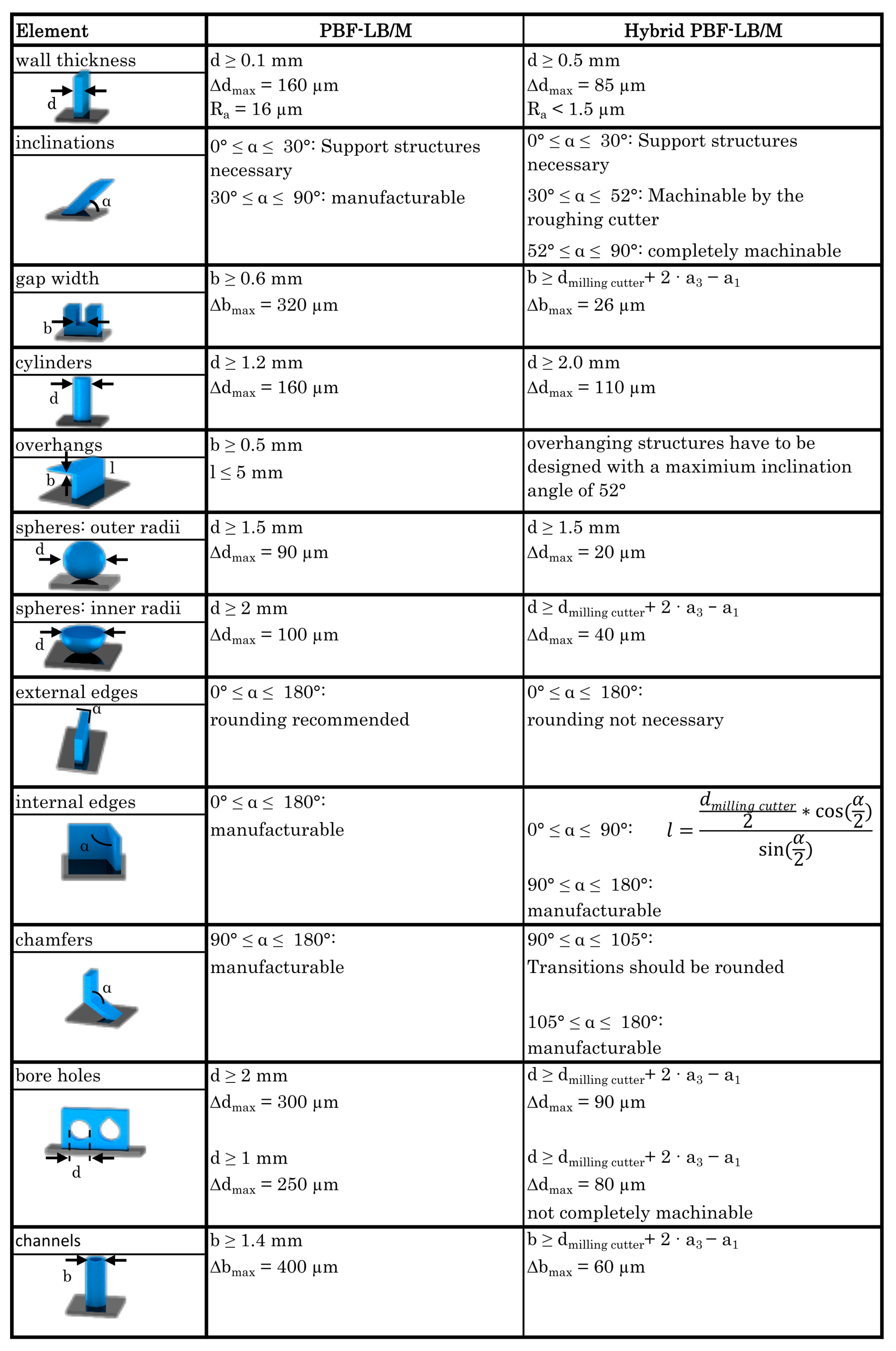
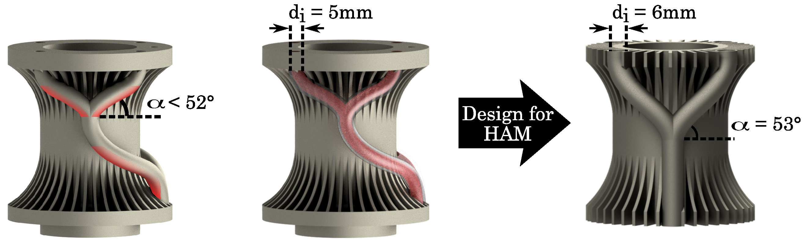
3.2. Design Guidelines

To ensure comparable conditions for the study, the structures for both the sole PBF-LB/M and the hybrid approach are fabricated during the same build and subsequently analyzed. Initially, the findings are presented for three different structures, exemplifying typical geometrical limits and specific process restrictions for the hybrid approach. Further findings for additional structures, representing typical geometries, are then presented in Figure A1, highlighting the design guidelines for the hybrid approach.

3.2.1. Minimum Wall Thickness

For a basic understanding of any manufacturing technology, the fabrication of fundamental structures has to be evaluated. The minimum vertically feasible wall thickness, as well as the geometrical deviation for the structures, is of upmost importance for a thorough understanding and application of the hybrid-additive manufacturing approach.
As the lower geometrical limit for the PBF-LB/M-process is well known to be defined by the laser spot size and the particle size of the powder, yet becoming increased by powder adherence and thermal mechanisms, the smallest manufactured wall width is physically realized by the additive process under study to be about d = 250 μm (nominal spot size of d spot = 200 μm at focus position). As energy is applied by the laser, thermal mechanisms generate an increase of the melt pool, leading to an additional melting and an adherence of surrounding powder particles [39]. Furthermore, the adhered powder and the thermal influence of the powder bed cause a geometrical deviation of about Δ d = 120 μm, persisting constantly for all thicknesses.
For the hybrid approach, the milling process expands the factors for the manufacturing of small structures. The mechanical machining and the resulting milling force impact, which the milling cutter induces on the built part, increase the minimum feasible wall thickness. As an experimental result, the smallest reliably built element exhibits a thickness of about d = 500 μm. Structure thickness below this value may be susceptible to damage during machining. The geometrical deviation can be reduced to a maximum of Δ d = 50 μm due to the subsequent machining of the structures.

3.2.2. Inclinations

The manufacturing of inclined components has been evaluated without the use of support structures, focusing on the forming of down-facing surfaces as well as the minimum fabricable angle using the high-speed milling system.
It was found that for the manufacturing of inclination angles up to α = 30°, components show very poor down-facing surfaces. In addition, residual stress leads to an up-warping of the components, causing collisions with the recoater. However, due to the high-speed milling system, the process can be continued, as the components can be flattened between the layers. To avoid thermal deformation as well as to exclude following process disruptions, support structures should be used, as reported for the PBF-LB/M-process before [40]. From an angle of α = 30°, inclinations can be manufactured without support structures, as the geometrical accuracy improves, and the residual stress can be excluded [41].
As mentioned before, the hybrid manufacturing of inclined structures is limited by the three-axis milling system and the geometry of the T-slot milling cutters, enabling a milling of undercuts. Consequently, down-facing surfaces with inclination angles up to α = 30° cannot be machined with the used processing parameters. Inclinations from α = 30° to 52° are milled using only the roughing cutters of step 1 and step 2 of the milling process, as the downwards movement can be performed. By virtue of the finishing start position, defining the distance to the last built layers, the finishing process can be executed starting from α = 52°, completing the subsequent machining and generating a smooth surface finish. Due to an adjustment of milling parameters, a machining of higher inclined surfaces is possible, in turn increasing the processing time significantly as well as the thermal distortion and burning.

3.2.3. Gap Width

Within the sole PBF-LB/M-process, gap widths are typically diminished by irregularly molten and adhered powder. Here, we find that a minimum gap width of d m i n = 250 μm with a deviation of Δ d = 350 μm in comparison to the constructed geometry is feasible. The deviations of both sides increase as a consequence of the thermal influence, surrounding the gap width, as reported before [35].
In contrast, for the hybrid-additive manufacturing approach, the minimum gap width is diminished by the three-axis milling system, combined with the geometry of the used milling cutter. As a material allowance is added on the constructed geometry, becoming removed gradually by the different steps of the milling process, the minimum gap width can be calculated following Equation (1). The minimum clearance d min is composed of the diameter of the used milling cutter d milling cutter , adding the total material allowance a t for both flanks. As the allowance for the roughing process a 1 is removed with the first milling path, it has to be subtracted. Hence, a minimum clearance of d min = 2.39 mm results, using a milling cutter with r = 1 mm and the introduced allowance of a 1 = 110 μm for both the roughing and the semi-finishing processes. As the allowance a 3 = 30 μm for the finishing process, it leads to a total material allowance of a t = 250 μm for the milling processes. Smaller gap widths result in higher machining loads for the milling cutter, inducing higher wear characteristics up to a breakage of the flank of the milling cutter.
d min = d milling cutter + ( 2 · a t ) a 1

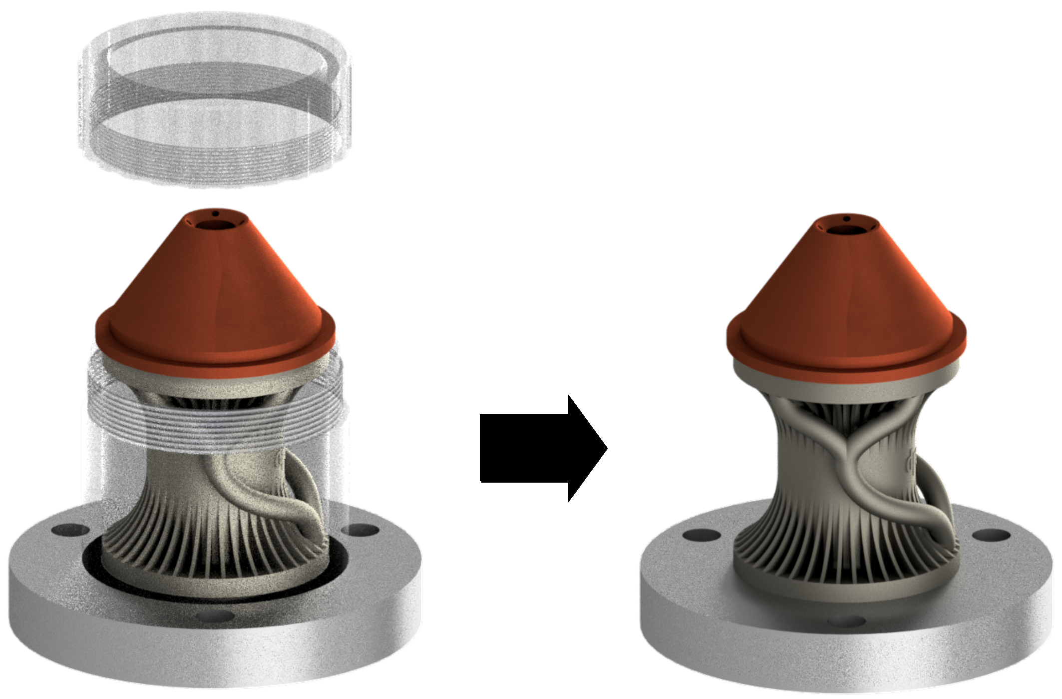
3.2.4. Extension to Further Structures

Following the so-far presented study and procedure to identify restrictions and define geometrical limitations of specific geometries, further structures are evaluated, and design guidelines are determined. In particular, while cylinders and outer radii of spheres are examined as analogous to the minimum wall thickness, inner radii of spheres and channels, as well as bore holes, are defined in accordance with Equation (1), following the definition of gap widths. In addition, chamfers, external and internal edges, and overhanging structures are investigated with respect to the three-axis milling system, similarly to the examination of inclined structures. A summarized catalog of construction rules is presented in Appendix A, comparing the sole PBF-LB/M and the hybrid-additive manufacturing.

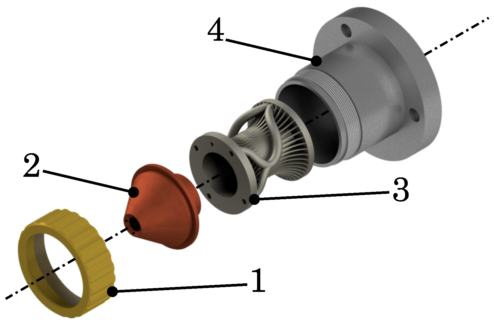
3.3. Redesign of the Powder Nozzle

In accordance with the previously established design guidelines, a powder nozzle for the DED-LB/M-process is to be redesigned. This redesigned nozzle will exemplify the potential of the design rule catalog. As a result, an adapted construction model for the hybrid-additive manufacturing process is provided. The different parts of the component are investigated with respect to the previously defined regulations, and problematic parts have to be changed, as a hybrid manufacturing process is used. The tools used are chosen following the standard equipment and optimized parameters for processing time and part quality. In addition, a surface conformal cooling is integrated, improving the performance of the DED-LB/M-process.

3.3.1. The Nozzle

The powder nozzle for the DED-LB/M-process consists of four parts, as provided in a modular setup (cf. Figure 5). The coupling ring (part 1) fixes the nozzle itself (part 2), shaping the powder jet for the DED-LB/M-process, onto the powder dispersion (part 3). The complete module is clamped by the carrier (part 4), which is, in turn, mounted on the machine.
Generally, in DED-LB/M, challenges arise due to the heat development during the manufacturing process, and the nozzle heats up with a thermal gradient across the entire component. As a result, powder particles adhere to the inside of the powder channels, perturbing the powder jet and, as a result, reducing process quality and, consequently, component quality by introducing residual stress.

3.3.2. Scope

To improve the performance of the DED-LB/M-process, different adjustments are successfully made, using the advantages of the hybrid-additive manufacturing. For an enhancement of the powder flow, the powder channels are milled completely, reducing the surface roughness and, subsequently, the frictional resistance for the powder particles. In addition to the passive cooling elements, an active cooling is integrated. For this, further channels are designed, surrounding the powder pipes as well as the DED-LB/M-nozzle. Again, the surface roughness is reduced with the in situ high-speed milling process, decreasing the amount of maintenance. Thus, the advantages of the hybrid approach are used for an improvement of the geometrical accuracy of the powder nozzle, as well as a reduction of the surface roughness of different channels, enabling an active, conformal cooling.
In order to enhance the usability of the powder nozzle after redesigning, the function has to be clarified, and essential geometrical characteristics should be defined. At first, the four powder outlets should be maintained, not modifying the DED-LB/M-process itself. For this, the dimensions of the complete powder nozzle are kept as well, still working with the same laser adjustments. The inner diameter of the powder dispersion can be reduced, not disturbing the manufacturing process.
It should be noted that a part of the powder nozzle, the powder dispersion, was manufactured by the PBF-LB/M-process, given that it was originally produced as a polymer part. For this, a redesign was performed for the laser manufacturing process. As the geometrical accuracy is not sufficient for the shaping of the powder jet, it was not possible to redesign the complete setting.

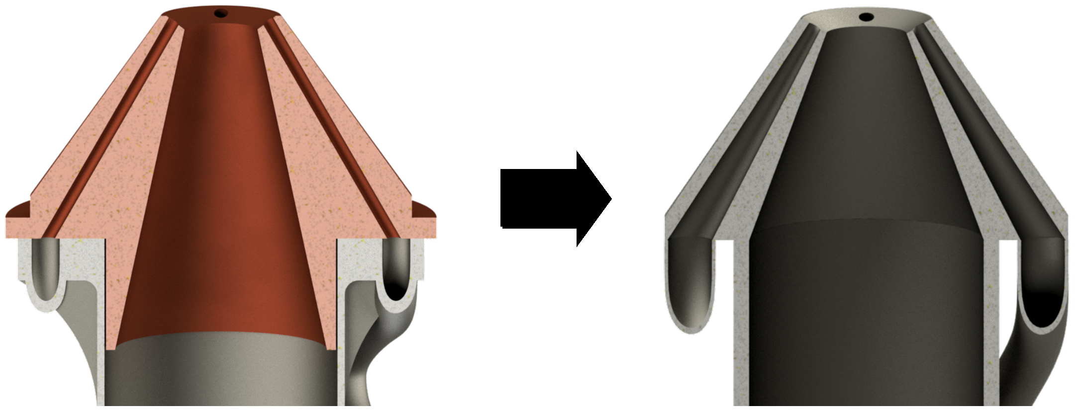
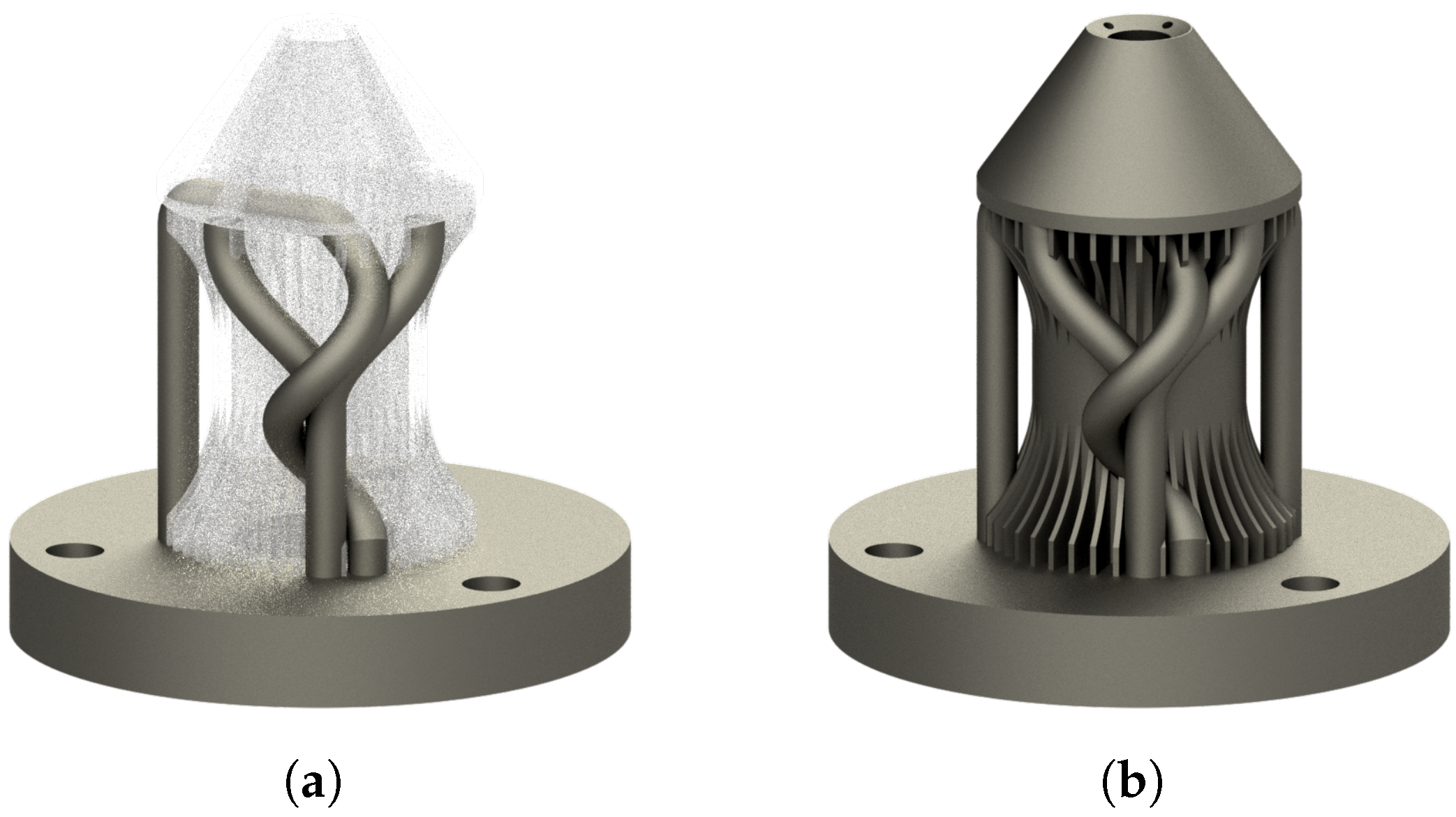
3.3.3. Orientation and Redundant Parts

Prior to the redesign, the orientation of the component has to be defined, as the build direction of the PBF-LB/M-process defines the necessity of support structures, and functional parts should be built up-facing [42]. According to this, the powder outlet of the nozzle is oriented in the build direction, ensuring a solid powder jet quality (cf. Figure 6).
Moreover, an analysis of the assembly group regarding redundant parts is possible, proving a saving of material as well as build time. The utilization of additive manufacturing enables the fabrication of an entire part in a single process, thereby eliminating the requirement for screw connections within the construction. With that, the coupling ring and the cladding of the carrier are not required anymore, as depicted in Figure 6. Subsequently, the component is made up of the nozzle itself, the powder dispersion, and the base plate of the carrier, being manufactured within one single part.

3.3.4. Analysis and Redesign

As the powder dispersion was designed for the PBF-LB/M-process, different design guidelines, regarding the additive manufacturing process, were respected. Starting with the analysis of small structures, the wall thickness of the passive cooling fins is analyzed, showing a reasonable constant thickness of d = 1 mm. The clearance between the single walls is adequate as well, ensuring a successful fabrication, as the component was designed for the PBF-LB/M-process.
As the core piece of the powder dispersion, the powder channels should be optimized, regarding their internal surface quality. In Figure 7, it is illustrated that the inclination angles of the powder channels underrun the limit for the high-speed milling system for a smooth surface finish. At the first curve, the channels possess a minimum inclination angle of α = 31° (red zone) to enable a manufacturing with the PBF-LB/M-process, dropping below the limit of α = 52° for a complete machining (cf. Section 3.2.2).
Additionally, considering the diameter of the T-slot milling cutter of d = 5 mm, the clearance of the powder channels does not enable manufacturing, as the diameter is exactly d = 5 mm. Please note that the channels are designed symmetrically for both sides, making an analysis of one powder channel sufficient.
For hybrid-additive manufacturing, the powder channels have to be redesigned, according to the afore-determined geometric limitations. Firstly, the channel diameter is set to d = 6 mm for the manufacturing using the T-slot cutter, in accordance with the defined minimum millable clearance, contingent on the diameter of the milling cutter (cf. Equation (1)). Secondly, the branch of the powder channels is excluded, and the two channels start separately, still supplying two different outlets each. With that, the minimum inclination angle can be set to α = 53°, avoiding a tool collision point for the milling processes (cf. Figure 7). Due to these changes in design, a complete machining of the powder channels by the three-axis milling system and the T-slot milling cutter is ensured, leading to a superior surface quality and a reduced frictional resistance of the powder particles. The surface quality can be improved with the subsequent in situ machining to R a = 1 μm, as reported before [25]. As previously stated, the functional segments of the nozzle design remain largely unchanged, preventing any significant changes for the DED-LB/M-process. For a smoother transition of the powder jet, the inlet of the nozzle is adjusted to the powder channels, diverging to the original geometry of the outlets (cf. Figure 8). Using the high-speed milling system, the top of the nozzle as well as the outlet of the powder channels are machined, guaranteeing the required geometrical accuracy.
In addition to the redesign of the powder dispersion, conformal cooling channels are integrated for a reduction in the nozzle temperature during the process. Starting directly next to the inlet of the powder channels, the pathway of the cooling tube is designed helically, surrounding the powder dispersion for an optimal cooling. Following the process-based design, an inclination angle of minimum α = 52° is guaranteed, allowing a complete machining due to the three-axis milling system. Solely, the transition between forward stroke and return flow is designed horizontally to not affect the powder channels (cf. Figure 9a) not being machined.

4. Conclusions

Based on an experimental study regarding general design rules for hybrid-additive manufacturing, combining PBF-LB/M and in situ high-speed milling using Inconel, particular focus is drawn to fundamental geometries being relevant for construction purposes of technical components. A series of structures, such as minimum feasible wall thickness, inner and outer diameter of cylinders and spheres, and maximum angle of inclination of overhanging structures, are analyzed, and the geometrical accuracies of boreholes, notches, chamfers, and inner and outer edges are investigated. The definition of a catalog of design guidelines summarizes the outcomes and forms a fundamental knowledge for the usage of the hybrid-additive manufacturing.
To exemplify the approach, a redesign of a powder dispersion of a DED-LB/M-nozzle was performed based on these design rules, enabling its hybrid-additive manufacturing. Due to the superior geometrical accuracy and surface quality of the hybrid-additive manufacturing, the entire design, including the nozzle itself, can be manufactured within one process cycle, rendering the assembly of different parts unnecessary. In addition, the accessible superior surface quality of the hybrid-additive manufacturing approach improves the powder flow inside the 3D-printed powder channels and avoids particle adhesion, thus improving powder supply to the DED-LB/M-process. Moreover, conformal cooling channels are designed, reducing the process temperature of the nozzle.
The determination of the construction rules is of the utmost importance for full exploitation of the hybrid-additive manufacturing. Furthermore, the design guide exemplifies the application of the hybrid approach onto existing components, improving part performance and expanding functionality.

Author Contributions

Conceptualization, D.S. and R.H.; methodology, D.S.; validation, D.S. and S.H.; formal analysis, D.S.; investigation, D.S. and S.H.; data curation, D.S. and S.H.; writing—original draft preparation, D.S.; writing—review and editing, D.S., C.E. and R.H.; visualization, D.S.; supervision, R.H.; project administration, R.H.; funding acquisition, R.H. All authors have read and agreed to the published version of the manuscript.

Funding

This research received no external funding.

Data Availability Statement

Data supporting this study are included within the manuscript.

Conflicts of Interest

The authors declare no conflicts of interest.

Appendix A. Construction Rules

Figure A1. Design guidelines for sole PBF-LB/M and the hybrid-additive manufacturing.
Jmmp 09 00088 g0a1

References

  1. Du, W.; Bai, Q.; Zhang, B. A Novel Method for Additive/Subtractive Hybrid Manufacturing of Metallic Parts. Procedia Manuf. 2016, 5, 1018–1030. [Google Scholar] [CrossRef]
  2. Lippert, R.B.; Lachmayer, R. Bionic inspired infill structures for a light-weight design by using SLM. In Proceedings of the DS 84: DESIGN 2016 14th International Design Conference, Dubrovnik, Croatia, 16–19 May 2016; pp. 331–340. [Google Scholar]
  3. Seabra, M.; Azevedo, J.; Araújo, A.; Reis, L.; Pinto, E.; Alves, N.; Santos, R.; Pedro Mortágua, J. Selective laser melting (SLM) and topology optimization for lighter aerospace componentes. Procedia Struct. Integr. 2016, 1, 289–296. [Google Scholar] [CrossRef]
  4. Cortina, M.; Arrizubieta, J.I.; Ruiz, J.E.; Ukar, E.; Lamikiz, A. Latest Developments in Industrial Hybrid Machine Tools that Combine Additive and Subtractive Operations. Materials 2018, 11, 2583. [Google Scholar] [CrossRef] [PubMed]
  5. Dilberoglu, U.M.; Gharehpapagh, B.; Yaman, U.; Dolen, M. Current trends and research opportunities in hybrid additive manufacturing. Int. J. Adv. Manuf. Technol. 2021, 113, 623–648. [Google Scholar] [CrossRef]
  6. Flynn, J.M.; Shokrani, A.; Newman, S.T.; Dhokia, V. Hybrid additive and subtractive machine tools – Research and industrial developments. Int. J. Mach. Tools Manuf. 2016, 101, 79–101. [Google Scholar] [CrossRef]
  7. Lorenz, K.A.; Jones, J.B.; Wimpenny, D.I.; Jackson, M.R. A review of hybrid manufacturing. In Proceedings of the Solid Freeform Fabrication, Austin, TX, USA, 10–12 August 2015; pp. 96–108. [Google Scholar]
  8. Manogharan, G.; Wysk, R.A.; Harrysson, O.L. Additive manufacturing–integrated hybrid manufacturing and subtractive processes economic model and analysis. Int. J. Comput. Integr. Manuf. 2016, 29, 473–488. [Google Scholar] [CrossRef]
  9. Xiong, W.; Jiang, L.J.; Baldacchini, T.; Lu, Y.F. Laser additive manufacturing using nanofabrication by integrated two-photon polymerization and multiphoton ablation. In Laser Additive Manufacturing; Brandt, M., Ed.; Elsevier: Amsterdam, The Netherlands, 2017; pp. 237–256. [Google Scholar] [CrossRef]
  10. Ye, Z.P.; Zhang, Z.J.; Jin, X.; Xiao, M.Z.; Su, J.Z. Study of hybrid additive manufacturing based on pulse laser wire depositing and milling. Int. J. Adv. Manuf. Technol. 2017, 88, 2237–2248. [Google Scholar] [CrossRef]
  11. Merklein, M.; Junker, D.; Schaub, A.; Neubauer, F. Hybrid Additive Manufacturing Technologies – An Analysis Regarding Potentials and Applications. Phys. Procedia 2016, 83, 549–559. [Google Scholar] [CrossRef]
  12. Lei, S.; Zhao, X.; Yu, X.; Hu, A.; Vukelic, S.; Jun, M.B.G.; Joe, H.E.; Yao, Y.L.; Shin, Y.C. Ultrafast Laser Applications in Manufacturing Processes: A State-of-the-Art Review. J. Manuf. Sci. Eng. 2020, 142, 031005. [Google Scholar] [CrossRef]
  13. Nicola, G.; Missell, F.; Zeilmann, R. Surface quality in milling of hardened H13 steel. Int. J. Adv. Manuf. Technol. 2010, 49, 53–62. [Google Scholar] [CrossRef]
  14. Sarafan, S.; Wanjara, P.; Gholipour, J.; Bernier, F.; Osman, M.; Sikan, F.; Molavi-Zarandi, M.; Soost, J.; Brochu, M. Evaluation of Maraging Steel Produced Using Hybrid Additive/Subtractive Manufacturing. J. Manuf. Mater. Process. 2021, 5, 107. [Google Scholar] [CrossRef]
  15. Sommer, D.; Götzendorfer, B.; Esen, C.; Hellmann, R. Design Rules for Hybrid Additive Manufacturing Combining Selective Laser Melting and Micromilling. Materials 2021, 14, 5753. [Google Scholar] [CrossRef]
  16. Shi, Q.; Gu, D.; Xia, M.; Cao, S.; Rong, T. Effects of laser processing parameters on thermal behavior and melting/solidification mechanism during selective laser melting of TiC/Inconel 718 composites. Opt. Laser Technol. 2016, 84, 9–22. [Google Scholar] [CrossRef]
  17. Wang, P.; Yang, F.; Li, P.; Zheng, B.; Fan, H. Design and additive manufacturing of a modified face-centered cubic lattice with enhanced energy absorption capability. Extrem. Mech. Lett. 2021, 47, 101358. [Google Scholar] [CrossRef]
  18. Hermann Becker, T.; Dimitrov, D. The achievable mechanical properties of SLM produced Maraging Steel 300 components. Rapid Prototyp. J. 2016, 22, 487–494. [Google Scholar] [CrossRef]
  19. Yasa, E.; Kempen, K.; Kruth, J.P. Microstructure and Mechanical Properties of Maraging Steel 300 After Selective Laser Melting. In Proceedings of the International Solid Freeform Fabrication Symposium, Austin, TX, USA, 9–11 August 2010. [Google Scholar] [CrossRef]
  20. Wang, D.; Wu, S.; Bai, Y.; Lin, H.; Yang, Y.; Song, C. Characteristics of typical geometrical features shaped by selective laser melting. J. Laser Appl. 2017, 29, 022007. [Google Scholar] [CrossRef]
  21. Aslantas, K.; Alatrushi, L.K.H. Experimental Study on the Effect of Cutting Tool Geometry in Micro-Milling of Inconel 718. Arab. J. Sci. Eng. 2021, 46, 2327–2342. [Google Scholar] [CrossRef]
  22. Ji, H.; Gupta, M.K.; Song, Q.; Cai, W.; Zheng, T.; Zhao, Y.; Liu, Z.; Pimenov, D.Y. Microstructure and machinability evaluation in micro milling of selective laser melted Inconel 718 alloy. J. Mater. Res. Technol. 2021, 14, 348–362. [Google Scholar] [CrossRef]
  23. Hwang, J.R.; Zheng, J.Y.; Kuo, P.C.; Huang, C.D.; Fung, C.P. Process Optimization of Inconel 718 Alloy Produced by Laser Powder Bed Fusion. Metals 2022, 12, 1494. [Google Scholar] [CrossRef]
  24. Balbaa, M.; Mekhiel, S.; Elbestawi, M.; McIsaac, J. On selective laser melting of Inconel 718: Densification, surface roughness, and residual stresses. Mater. Des. 2020, 193, 108818. [Google Scholar] [CrossRef]
  25. Sommer, D.; Hornung, S.; Esen, C.; Hellmann, R. Surface roughness optimization of hybrid PBF-LB/M-built Inconel 718 using in situ high-speed milling. Int. J. Adv. Manuf. Technol. 2024, 132, 1741–1751. [Google Scholar] [CrossRef]
  26. Wüst, P.; Edelmann, A.; Hellmann, R. Areal Surface Roughness Optimization of Maraging Steel Parts Produced by Hybrid Additive Manufacturing. Materials 2020, 13, 418. [Google Scholar] [CrossRef] [PubMed]
  27. Sommer, D.; Esen, C.; Hellmann, R. Static and Dynamic Mechanical Behaviour of Hybrid-PBF-LB/M-Built and Hot Isostatic Pressed Lattice Structures. Materials 2023, 16, 3556. [Google Scholar] [CrossRef] [PubMed]
  28. Lopez de Lacalle, L.N.; Angulo, C.; Lamikiz, A.; Sanchez, J.A. Experimental and numerical investigation of the effect of spray cutting fluids in high speed milling. J. Mater. Process. Technol. 2006, 172, 11–15. [Google Scholar] [CrossRef]
  29. Suresh Kumar Reddy, N.; Venkateswara Rao, P. Experimental investigation to study the effect of solid lubricants on cutting forces and surface quality in end milling. Int. J. Mach. Tools Manuf. 2006, 46, 189–198. [Google Scholar] [CrossRef]
  30. Cheng, B.; Shrestha, S.; Chou, K. Stress and deformation evaluations of scanning strategy effect in selective laser melting. Addit. Manuf. 2016, 12, 240–251. [Google Scholar] [CrossRef]
  31. Mazur, M.; Leary, M.; Sun, S.; Vcelka, M.; Shidid, D.; Brandt, M. Deformation and failure behaviour of Ti-6Al-4V lattice structures manufactured by selective laser melting (SLM). Int. J. Adv. Manuf. Technol. 2016, 84, 1391–1411. [Google Scholar] [CrossRef]
  32. Metelkova, J.; Vanmunster, L.; Haitjema, H.; van Hooreweder, B. Texture of inclined up-facing surfaces in laser powder bed fusion of metals. Addit. Manuf. 2021, 42, 101970. [Google Scholar] [CrossRef]
  33. Koutiri, I.; Pessard, E.; Peyre, P.; Amlou, O.; de Terris, T. Influence of SLM process parameters on the surface finish, porosity rate and fatigue behavior of as-built Inconel 625 parts. J. Mater. Process. Technol. 2018, 255, 536–546. [Google Scholar] [CrossRef]
  34. Leary, M.; Mazur, M.; Williams, H.; Yang, E.; Alghamdi, A.; Lozanovski, B.; Zhang, X.; Shidid, D.; Farahbod-Sternahl, L.; Witt, G.; et al. Inconel 625 lattice structures manufactured by selective laser melting (SLM): Mechanical properties, deformation and failure modes. Mater. Des. 2018, 157, 179–199. [Google Scholar] [CrossRef]
  35. Adam, G.A.; Zimmer, D. Design for Additive Manufacturing—Element transitions and aggregated structures. CIRP J. Manuf. Sci. Technol. 2014, 7, 20–28. [Google Scholar] [CrossRef]
  36. Gibson, I.; Rosen, D.; Stucker, B.; Khorasani, M. (Eds.) Additive Manufacturing Technologies, 3rd ed.; Springer International Publishing: Berlin/Heidelberg, Germany, 2021. [Google Scholar]
  37. Yap, C.Y.; Chua, C.K.; Dong, Z.L.; Liu, Z.H.; Zhang, D.Q.; Loh, L.E.; Sing, S.L. Review of selective laser melting: Materials and applications. Appl. Phys. Rev. 2015, 2, 041101. [Google Scholar] [CrossRef]
  38. ISO 13322-2; Particle Size Analysis-Image Analysis Methods-Dynamic Image Analysis Methods. International Organization for Standardization: London, UK, 2021. [CrossRef]
  39. Kumar, P.; Farah, J.; Akram, J.; Teng, C.; Ginn, J.; Misra, M. Influence of laser processing parameters on porosity in Inconel 718 during additive manufacturing. Int. J. Adv. Manuf. Technol. 2019, 103, 1497–1507. [Google Scholar] [CrossRef]
  40. Kranz, J.; Herzog, D.; Emmelmann, C. Design guidelines for laser additive manufacturing of lightweight structures in TiAl6V4. J. Laser Appl. 2015, 27, S14001. [Google Scholar] [CrossRef]
  41. Oh, Y.; Ko, H.; Sprock, T.; Bernstein, W.Z.; Kwon, S. Part decomposition and evaluation based on standard design guidelines for additive manufacturability and assemblability. Addit. Manuf. 2021, 37, 101702. [Google Scholar] [CrossRef]
  42. Adam, G.A.O.; Zimmer, D. On design for additive manufacturing: Evaluating geometrical limitations. Rapid Prototyp. J. 2015, 21, 662–670. [Google Scholar] [CrossRef]
Figure 1. Schematic illustration of the hybrid-additive manufacturing unit [25].
Jmmp 09 00088 g001
Figure 2. Depiction the different steps of the hybrid-additive manufacturing process with (a) the total material allowance a t and the spared finishing allowance a 3 for the next process cycle; (b) the roughing allowance a 1 , (c) the semi-finishing allowance a 2 , and (d) the finishing allowance a 3 , becoming detached by ball end mills with r = 1 mm [25].
Jmmp 09 00088 g002
Figure 3. (a) Finishing cutter, (b) removal of the staircase effect, (c) milling of inclined surfaces using a T-slot milling cutter, (d) T-slot milling cutter.
Jmmp 09 00088 g003
Figure 4. (a) Measured powder size distribution for new, sieved, and oversized particles. (b) Powder morphology for sieved powder.
Jmmp 09 00088 g004
Figure 5. Modular setup of the powder nozzle.
Jmmp 09 00088 g005
Figure 6. Optimized powder nozzle design and build orientation for the hybrid-additive manufacturing process.
Jmmp 09 00088 g006
Figure 7. Analysis of the powder channels, showing the highly inclined powder channels, the undersized inner diameter of the powder channels, and the redesigned powder dispersion.
Jmmp 09 00088 g007
Figure 8. Merging the powder nozzle and dispersion into one part, optimizing the powder channels.
Jmmp 09 00088 g008
Figure 9. (a) Integration of the active cooling into the redesigned powder nozzle, surrounding the powder channels. (b) Redesigned DED-LB/M-nozzle for the hybrid-additive manufacturing.
Jmmp 09 00088 g009
Table 1. PBF-LB/M-parameters.
Laser Power PL/WScan Speed vs/(mm/min)Hatch Distance dh/mm
Area3207000.14
Contour3201400-
Support3207000.12
Table 2. Process parameters for the different milling steps.
Infeed an/μmZ-Pitch ae,z/μmSpindle Speed n/(1/min)Feed Rate vc/(mm/min)
Roughing1101504800240
Semi-finishing1101004800240
Finishing30809600240
Table 3. Chemical composition of Inconel 718 powder [37].
ElementNiCrNbMoTiAlCMnSiFe
Wt%50–5517–214.8–5.52.8–3.30.7–1.20.2–0.8<0.1<0.4<0.4balance
Disclaimer/Publisher’s Note: The statements, opinions and data contained in all publications are solely those of the individual author(s) and contributor(s) and not of MDPI and/or the editor(s). MDPI and/or the editor(s) disclaim responsibility for any injury to people or property resulting from any ideas, methods, instructions or products referred to in the content.

