Article

Effect of Hot Isostatic Pressing and Sequenced Heat Treatment on the Mechanical Properties of Hybrid Additive Manufactured Inconel 718 Components

1
Applied Laser and Photonics Group, University of Applied Sciences Aschaffenburg, Wuerzburger Street 45, 63743 Aschaffenburg, Germany
2
Applied Laser Technologies, Ruhr University Bochum, Universitaetsstr 150, 44801 Bochum, Germany
*
Author to whom correspondence should be addressed.
J. Manuf. Mater. Process. 2025, 9(11), 378; https://doi.org/10.3390/jmmp9110378
Submission received: 9 October 2025 / Revised: 6 November 2025 / Accepted: 17 November 2025 / Published: 19 November 2025
(This article belongs to the Special Issue Advances in Hybrid Manufacturing)

Abstract

We report on the effect of hot isostatic pressing combined with solution and ageing treatment in different sequences on the mechanical properties of Inconel 718 specimens, which in turn have been fabricated by a hybrid additive manufacturing approach. The latter combines conventional laser powder bed fusion and in-situ high speed milling, yielding superior surface quality as being quantified by R a about 1 μm. In a comparative study between hybrid additively manufactured parts and those built without milling, we find that, in general, any combination of heat treatment leads to a higher ultimate tensile strength and an improved endurance limit, while, however, hot isostatic pressing affects these figures of merit most. In addition, metallographic analysis reveals increased density and hardness for hot isostatic pressed parts due to precipitation hardening. These improvements of the mechanical properties are found to be even more pronounced when the printed parts are manufactured by the hybrid additive approach, i.e., for parts with improved surface conditions.

1. Introduction

Additive manufacturing, especially laser powder bed fusion (PBF-LB/M), is nowadays used for the fabrication of small series and prototypes for various industrial applications [1,2], benefiting from the high freedom of design, allowing the realization of functionally integrated, high-performance parts, also from a variety of printable materials [3,4,5]. In particular, Inconel 718 (IN718) is a frequently employed material for high-temperature applications with excellent tensile strength [6,7]. Its hardness and ultimate tensile strength (UTS) can be further improved by a temperature-driven hardening and thus a precipitation of γ and γ phases [8].
However, though the advantages of additive manufacturing are numerous, also disadvantages occur. Due to the thermal process and the powder bed-based process, porosities emerge as well as a high surface roughness develops, diminishing the mechanical properties of PBF-LB/M-built components [9,10]. These disadvantages necessitate post-processing of manufactured components, to improve the metallographic and surface properties. Thermal post-processing, e.g., solution and ageing treatments as well as hot-isostatic pressing (HIP), leads to a reduction of porosities and enhanced mechanical properties, whereat HIP achieves the best improvements [11,12,13].
Furthermore, subsequent mechanical machining, e.g., milling or turning, or chemical treatment are used for a reduction of the surface roughness. Combining additive and subtractive methods in-situ defines hybrid additive manufacturing technologies, such as laser metal deposition in combination with multi-axis milling [14]. In regards to powder bed fusion, a promising hybrid approach combining PBF-LB/M with in situ high-speed milling has recently been applied [15,16]. This hybrid technique allows a direct machining of the components outer contour, inner laying features and high aspect ratios, as the 3D printing process can be interrupted on a defined layer basis to mill the thus far printed geometry [17,18].
Also, because the thermal post-processing and the surface conditions directly affect mechanical properties, a comprehensive metallographic evaluation of built specimens is of upmost importance. Several studies investigate the effect of ageing treatments and HIP on the mechanical properties [19,20] and microstructural changes [21,22,23] of 3D printed Inconel parts, determining an increase of hardness and UTS as a consequence of γ - and γ -precipitation [24,25]. Furthermore, different post-processing surface modifications, e.g., electro- and laserpolishing [26] as well as mechanical machining [27], are evaluated, leading to improved mechanical properties.
Against this background, here we report on the effect of hot isostatic pressing combined with solution and ageing treatment in different sequences on the mechanical properties of PBF-LB/M-built Inconel 718 specimens using hybrid additive manufacturing that combines conventional PBF-LB/M and in situ high-speed milling. Different HT-cycles are investigated in combination with stress relief and solution treatment. For the evaluation, the UTS and the fatigue behaviour are determined, being compared between the as-built state of the components, i.e., without milling, and the hybrid-built parts. While HIP, in general, leads to an improvement in static and dynamic mechanical load behaviour, the enhanced surface conditions of the hybrid-built parts also exhibit improved mechanical properties.

2. Materials and Methods

For hybrid additive manufacturing, a Lumex Avance-25 (Matsuura, Fukui, Japan) is used, integrating a high-speed milling spindle into a PBF-LB/M-machine. Conventional PBF-LB/M is performed using a Yb-fibre laser with a maximum laser power of P L = 500 W , a spot size of d spot = 200 μm at focus position, and an operating wavelength of λ = 1070 n m . As the focus of this contribution is on the effect of hot isostatic pressing and thermal treatments, previously optimized process parameters are used for the manufacturing of the test specimen, as the parameters are set to P L = 320 W for the Laser power, v s = 700 m m /min for the scan-speed, h l = 50 μm for the layer height, and d h = 140 μm for the hatch distance [16].
For the hybrid manufacturing process, a milling spindle is directly integrated, enabling an in situ machining with a maximum turning velocity of N = 45,000 1/min with a 3-axis milling system and a twenty-fold tool magazine. As the milling takes place directly within the PBF-LB/M-process, the use of any cooling lubricant is not possible due to the powder bed. Furthermore, a material allowance of a t = 250 μm is added during PBF-LB/M, getting removed gradually within the milling process. As depicted in Figure 1a, the additive process alternates with the milling process, machining the surfaces during an interruption of the PBF-LB/M every 10 layers. Within the first two steps, the roughing and the semi-finishing process, most of the added material allowance a 1 / 2 = 110 μm is detached, working from the top of the component to the bottom. Subsequently, the finishing process dissipates the remaining a 3 = 30 μm , ensuring the final part geometry as well as a good surface quality. For this, the contour is machined from the bottom to the top, sparing the last built layers, as depicted in Figure 1a. Again, previously optimized process parameters are used, as specified in Table 1 [16].
For the evaluation of the mechanical properties, standard tensile test specimens are manufactured vertically, as depicted in Figure 1b. According to ISO 6892-1 and DIN 50125 [28,29], a test geometry on the basis of Geometry E for flat tensile specimen is defined with a 0 = 3 m m , b 0 = 8 m m , B = 14 m m , L 0 = 32 m m , and r 0 = 20 m m . To enable a complete manufacturing of the components, two different milling cutters are employed. For the test area and the lower transition area, a ball end mill with a cutting radius of r = 1 m m is used. Due to the specimens geometry, the upper transition area is machined by a T-slot milling cutter, allowing us to mill undercut surfaces with the 3-axis milling system. Within the PBF-LB/M and the hybrid process, specimen end geometries are consistent, considering tolerances and geometrical deviations of the PBF-LB/M and the hybrid process, as reported before [17].
Within this study, Inconel 718 (IN718), a Ni-based superalloy is used, as the chemical composition is depicted in Table 2. IN718 is a precipitation hardening alloy with a high corrosion and thermal resistance, showing a high tensile strength and good mechanical characteristics. For the PBF-LB/M-process, gas atomized powder (Heraeus, Hanau, Germany) with a particle size distribution of x c min = 15 μm to 45 μm , peaking at x c min = 24 μm , is used [17].
The static mechanical load behaviour is tested with an universal testing machine AG-X plus (Shimadzu, Kyoto, Japan), averaging the Ultimate Tensile Strength (UTS) out of seven specimens for every state of the material. A maximum applicable force of F max = 50 kN and an extensometer with a measurement accuracy of 0.5 μm is used for the testing.
For the fatigue testing, a linear electrodynamic testing machine, UD020 (STEP Engineering, Resana, Italy), is employed. A force controlled fatigue test, following ASTM E466, is conducted with a sinusoidal oscillation, an applied test frequency of f = 100 Hz and a maximum applied load of F max = 14 kN . With a stress ratio of R = 0, a multitude of amplitudes is tested to evaluate the different regimes of fatigue as well as the endurance limit with a Wöhler-diagram. For every amplitude, a minimum of three specimens is tested. Within this, the high cycle fatigue regime is described by the gradient k, showing the median fatigue strength. A maximum number of cycles of n = 1.5 × 10⁷ is used, defining the endurance limit according to the staircase-method and the IABG-method [30].
For the hardness and porosity measurements as well as for the microstructural analysis, the specimens are metallographically prepared by grinding (P80, P320, P600, P800, P1200, P2400) and polishing with diamond suspension (3 μm , 1 μm ). The hardness is measured, using a Vickers intent measurement, following DIN EN ISO 6507-1 [31]. with a universal testing machine (Falcon-5000, Innovatest, Maastricht, Netherlands). For three specimens for each material state, a number of ten intents is used, averaging the results of 30 measurements in total. An intent spacing of 1 mm is used and the height is varied in regard to the build height. For the evaluation of the density, polished micrograph sections are analysed by optical microscopy (DFC450, Leica, Wetzlar, Germany), identifying the porosity ratio by image processing, following ASTM E2109 [32]. For this, a number of 35 images of each specimen is recorded, evaluating the area percentage of voids within the sample. For the microstructural analysis, the specimens are etched with an etching agent according to Adler, which consists of Hydrochloric acid, Iron(III)chloride, Copper ammonium chloride and distilled water. An immersion etching for about 45 s is performed, followed by an inspection of the microstructure with the optical microscope.
Surface analysis is performed with a Laser Scanning Microscope (LSM) VK-X3200 (Keyence, Osaka, Japan) and a 20× magnification. A multitude of profiles for a batch of specimens are measured, quantifying the surface quality with R a and R z . According to ISO 4288 [33]. a length of 4.8 m m is recorded, using a short-wave profile filter of λ s = 2.5 μm a cut-off of λ c = 0.8 μm . The recorded profile is evaluated with a multiple line roughness measurement with 13 lines, averaging the roughness parameters.
For the thermal post-processing, different cycles for Hot Isostatic Pressing (HIP) are performed, as depicted in Figure 2. With this, differences of a Solution Treatment (ST) process prior and after HIP are evaluated, as well as different sustain times are tested. The sustain times and temperatures are chosen on the basis of the AMS 5662 [34]. representing a standard for the application in the aviation and aerospace industry.
At first, a HIP is performed with ϑ HIP = 1150 °C and p = 150 MPa for 4 h. Subsequently, an ST with ϑ ST = 980 °C is utilised as well as a Double Ageing (DA) procedure with ϑ DA 1 = 720 °C and ϑ DA 2 = 620 °C for 8 h, and 10 h, respectively is conducted.
Additionally, HIP-cycles are performed, starting with a ST process at ϑ ST = 1065 °C for 1 h. Afterwards, a HIP at ϑ HIP = 1150 °C and p = 150 MPa follows, varying the sustain time between 3 h, 4 h, and 5 h. Furthermore, the DA-procedure is conducted again, summarized in Table 3. While air cooling is used for the transitions between the single steps, a furnace cooling is performed within the DA-procedure, as schematically illustrated in Figure 2.

3. Results

Within this section, the results of the static and dynamic mechanical testing are presented, evaluating the UTS and the fatigue behaviour for the different states of the material. At first, the mechanical properties of the heat-treated components are analysed, comparing the sole PBF/LB-M-built specimen with and without heat treatment. Secondly, the tensile strength as well as the fatigue behaviour of hybrid additive manufactured components are investigated, revealing the impact of the improved surface quality on the mechanical properties. In Section 4, a comprehensive discussion is given.

3.1. Hot Isostatic Pressing

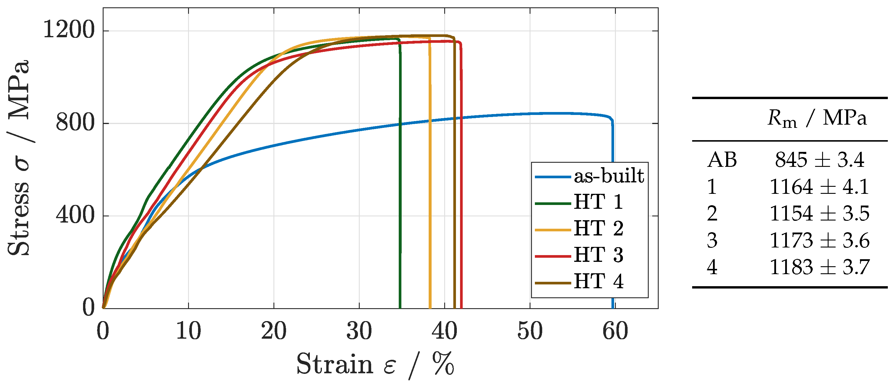
The static mechanical load behaviour shows significant differences for the heat-treated (HT) components in comparison to the as-built state of the IN718, as the stress–strain diagram in Figure 3 shows.
For the as-built state, an UTS of σ UTS = 844 MPa can be determined, developing a long elongation zone as well as a necking zone before the final failure occurs. A very ductile tensile behaviour is shown, as typically generated by the high cooling rates of the PBF-LB/M process for IN718 [19].
The HT 1 increases the UTS in comparison to the as-built state, showing an UTS of σ UTS = 1167 MPa. Furthermore, the elongation is reduced, as due to the ageing procedure, a very strong material develops, improving the tensile strength significantly (cf. Figure 3).
For the ST + HIP cycles, the elongation is reduced and the tensile strength is increased significantly in comparison to the as-built state, as an UTS of σ UTS = 1154 MPa (HT 2), respectively σ UTS = 1175 MPa (HT 3) and σ UTS = 1179 MPa (HT 4) is reached. This results in similar mechanical properties to those of forged components after heat treatment ( σ UTS = 1231 MPa) [6]. The precipitation hardening during the DA-process leads to an immense strengthening of the components, even though a very brittle material structure develops. Consequentially, the necking zone is excluded completely and the UTS is equalised with the breaking strength.
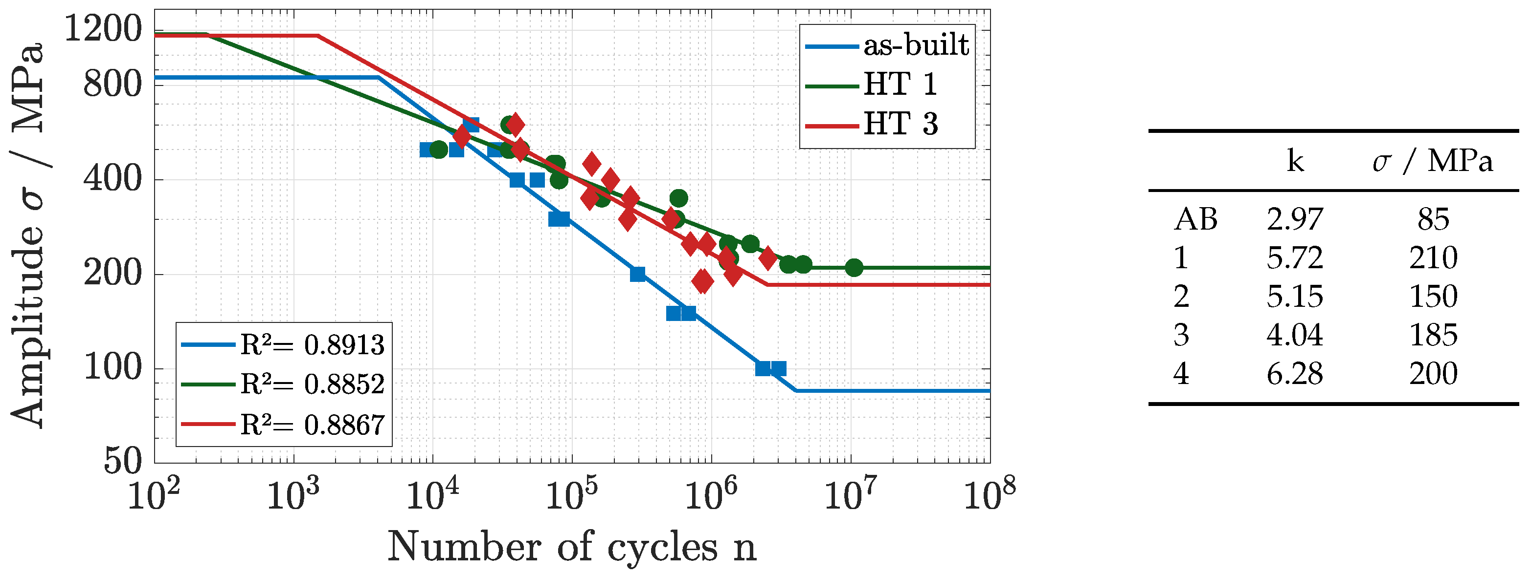
The dynamic mechanical load behaviour is tested for the HT 1 and HT 3, evaluating the differences of prior- and post-processing stress relief, respectively solution treatment (cf. Figure 4).
The as-built state with the developed ductile material shows a long Low Cycle Fatigue (LCF) regime, as it merges into the High Cycle Fatigue (HCF) regime at a number of cycles of about n = 4 × 10³. The HCF regime is described by a gradient of k = 2.97 ( R 2 = 0.8913 ), reaching the Very High Cycle Fatigue (VHCF) regime at a load of about σ = 125 MPa. Finally, the endurance limit can be determined with σ = 85 MPa, as a failure within 1.5 × 10⁷ cycles is excluded.
For the HT 1 cycle, the fatigue behaviour differs significantly. Emanating from the very high UTS, the LCF regime merges into the HCF regime at a very early stage with a number of cycles of about n = 2.7 × 10². The HCF regime is improved at an applied load of about σ = 500 MPa, getting described by the gradient of k = 5.78 and a consistently good agreement between experimental data and the fitted regression line ( R 2 = 0.8852 ). Reaching the VHCF regime at an amplitude of σ = 250 MPa with n = 2 × 10⁶ cycles, the VHCF regime as well as the endurance limit, determined with σ = 210 MPa, can be improved significantly as against the as-built state of the material.
Similarly, the HT 3 leads to an improvement of the fatigue behaviour in comparison to the as-built state. Starting with the LCF regime, the HT 3 components show an improvement, as the HCF regime is reached at about n = 1.5 × 10³. Furthermore, the HCF regime is described with the gradient of k = 4.04, maintaining a better dynamic load behaviour. A good agreement between experimental data and fitted regression continues to be ensured ( R 2 = 0.8867 ). Within the HCF regime, the Wöhler-curve passes the one of the HT 1 cycle, as lower numbers of cycles are performed. Nevertheless, an endurance limit of σ = 185 MPa is determined, improving the as-built state of the IN718 significantly.
On conclusion, the HT 1 treatment leads to the highest UTS as well as to the best endurance limit with σ = 210 MPa. Despite this, the LCF regime of the HT 3 is enlarged, and during the HCF regime, the HT 1 develops a significant improvement in fatigue behaviour, becoming quantified by an increase of 25 MPa in the endurance limit.

3.2. Hybrid Additive Manufacturing

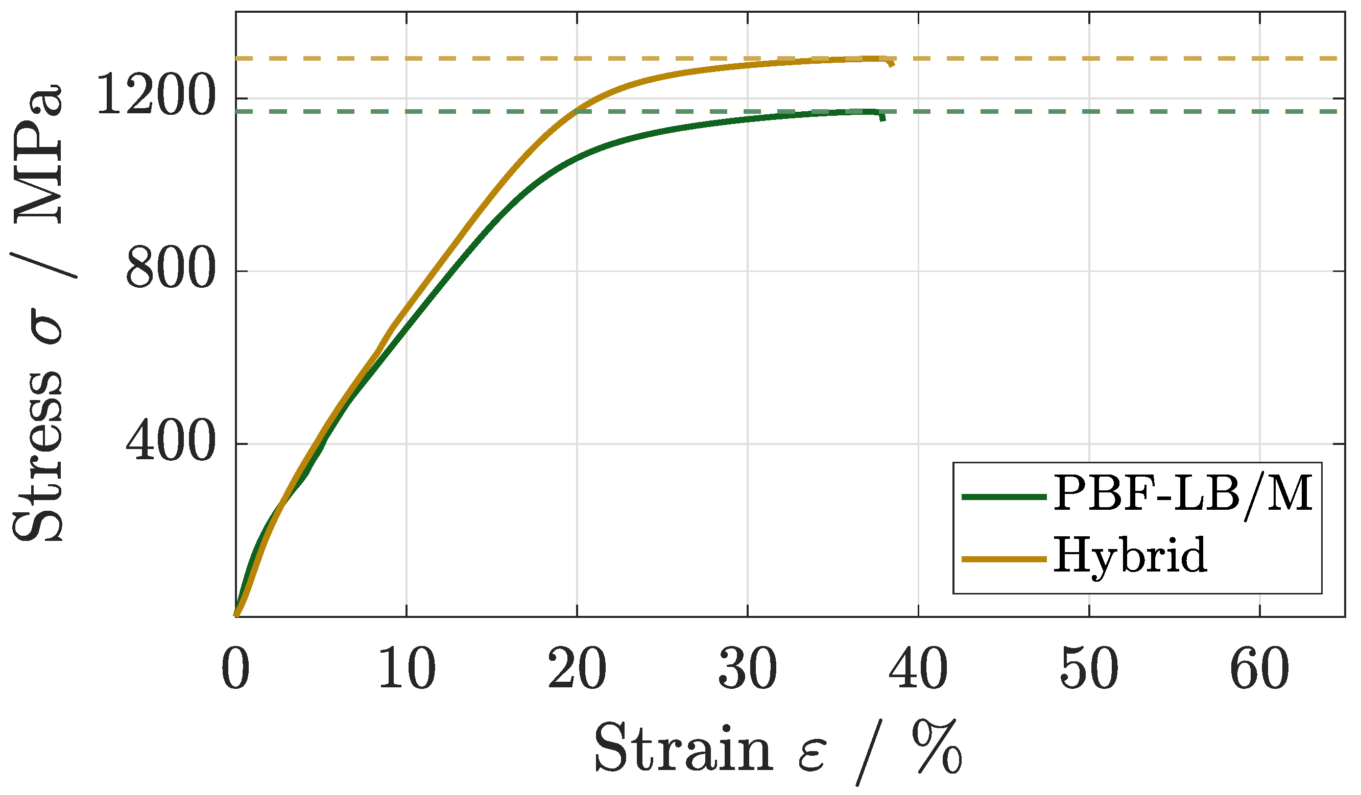
For the evaluation of the impact of the hybrid additive manufacturing on the mechanical properties, hybrid manufactured components are heat treated following the HT 1 cycle. As stated before, the UTS of HT 1 is reached at σ UTS = 1164 ± 4.1 MPa, showing a strengthened, but more brittle material in comparison to the as-built state (cf. Figure 5).
The hybrid additive manufacturing leads to an improvement of the static mechanical load behaviour, as an UTS of σ UTS = 1291 ± 2.7 MPa is reached. The progress of the stress-strain curve is very similar, as the improvement develops during the strain hardening zone and the offset is maintained until the point of breakage.
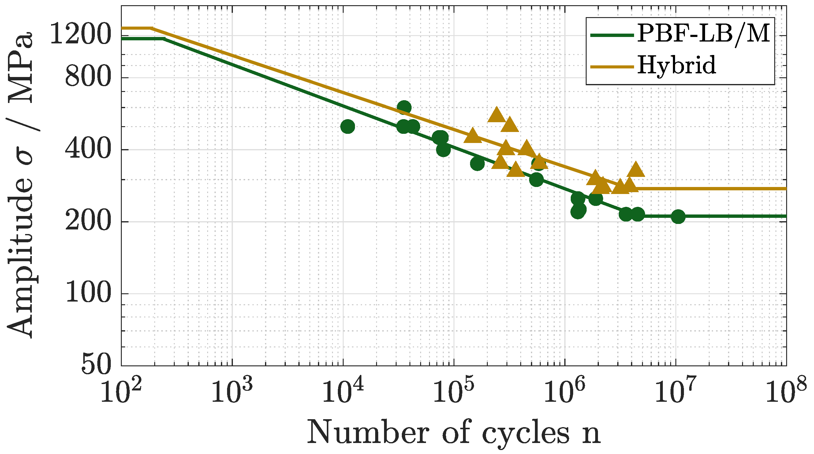
For the dynamic mechanical load behaviour, a difference between the PBF-LB/M- and the hybrid built components arises as well, as shown in Figure 6. The HT 1 shows, as stated before, a very short LCF regime, merging into the HCF regime at a very early state. The HCF regime is described by a gradient of k = 5.72, merging into the VHCF regime at about σ = 250 MPa. The endurance limit can be determined with σ = 210 MPa.
The hybrid approach leads to an improvement in the different regimes of fatigue, as constantly a higher number of cycles is performed by the in situ post-processed components. Similarly to the PBF-LB/M-state, the LCF regime merges at a very early stage into the HCF regime, as depicted in Figure 6. The Wöhler-curve is flattened, getting described by a gradient of k = 6.41, further increasing the number of cycles at lower amplitudes. The VHCF regime is reached at about σ = 300 MPa, transitioning into the endurance limit at σ = 275 MPa.

4. Discussion

Within this section, material characteristics are discussed, classifying the results of the mechanical testing. For the different HIP-cycles, metallographic parameters such as hardness and density are investigated. Additionally, a surface analysis is performed, comparing the surface roughness of PBF-LB/M with hybrid-built components with respect to the impact on mechanical properties.

4.1. Density

For the PBF-LB/M process, appropriate manufacturing parameters are of upmost importance for the generation of good melting and part quality. For a determination of manufacturing quality, part density and hardness have been established, as these are highly affected by process parameters and part properties such as mechanical properties [35].
The as-built state of the IN718 shows a density of ρ = 99.17%. As porosities arise due to gas inclusions during the PBF-LB/M process, commonly achieved densities are numbered from ρ = 98.2% to 99.8% [35,36].
For the HT 1, a density of ρ = 99.96% is generated, increasing the density of the as-built state. Similarly, the ST + HIP cycles leads to a density from ρ = 99.35% to 99.71%, reducing the porosity as well. Heat treatments, especially HIP lead to an increase of density, as inlaying porosities are reduced by the isostatic applied gas pressure, enabled by thermal activated mechanisms [12]. For HT 2, HT 3, and HT 4, prior to the HIP, the ST causes a homogenisation of the texture, minimising residual stress. Furthermore, pores can become downsized at that point already and defects can be redistributed by virtue of thermal activated diffusion. Similar to this, the post-HIP solution treatment of HT 1 reinforces the mechanisms of material change due to a grain coarsening as porosities are minimised simultaneously.
The HIP itself, analogous for both heat treatments, leads to a minimal plastic deformation of the components, including a reduction of porosities. Furthermore, the diffusion process is intensified by the thermal activation and prior ST as well as post-processed ST [37]. Additionally, during the DA-process, a more coarse-grained structure develops, as a precipitation of the γ - and γ -phase is forced. Due to the movement of grain boundaries, internal defects are closed, increasing the density of the material [19].

4.2. Hardness and Microstructure

For the hardness, the as-built state shows a Vickers-hardness of 307 HV10, as a very ductile material is developed within the PBF-LB/M-process. High cooling rates of the layerwise manufacturing lead to a very fine grained microstructure, encouraging a ductile material state [6]. In addition to the melting paths of the PBF-LB/M process, signs of grain boundaries are visible in Figure 7, showing a very fine grained structure. Within the heat treatments, the hardness can be improved up to 456 HV10 for HT 1, respectively, to 455 HV10 (HT 2), 438 HV10 (HT 3), and 487 HV10 (HT 4).
While the HIP leads to a homogenisation of the material structure and an increase in hardness by virtue of the applied gas pressure, the DA-procedure causes a change in material structure and a subsequent hardening. During the HIP, the brittle δ - and Laves-phases get dissolved, raising the resilience of the material [12]. As depicted in Figure 7, NbC carbides precipitate along the grain boundaries and the remaining δ -phases are visible in needle-shaped precipitations across the structure (red arrows). Furthermore, the melting paths are not visible, as the solution temperature for the segregation patterns is exceeded. A grain boundary movement is enabled, leading to a coarse-grained structure [38]. Within the DA, a precipitation of the γ - and γ -phase is forced, strengthening the main γ -Matrix of the IN718 and leading to an improvement in hardness [13]. Consequentially, the UTS increases significantly, as shown in Figure 3. The reduction of elongation as well as the shortened LCF-regime for both heat-treated states can be attributed to the material change during hardening.
Furthermore, the homogenisation of the material structure is intensified by the post-HIP solution treatment, as a lower hardness is observed as for HT 1-procedure. Due to this, the HCF regime as well as the endurance limit are increased for the HT 1, as shown in Figure 4.

4.3. Surface Analysis

Within the PBF-LB/M-process, irregularities in surface texture arise, as a surface roughness of R a = 13.6 ± 3.2 μm and R z = 74.3 ± 12.1 μm is measured. The melt pool, geometrically determined by the laser spot size and the applied energy density, causes a heat affected zone, getting conducted to the surrounding material. Melt track irregularities and balling arise and satellite powders are molten to the components surface [36]. Furthermore, the laser melting and the solidification of the material generate a material expansion and contraction. Residual stress gets introduced, leading to microscopic cracks in the material, mostly occurring at the surface of the components [36].
For the hybrid manufacturing, the components show a highly increased surface quality. Due to the three-step high-speed milling process, a very continuous surface can be fabricated, mostly excluding adhered particles and irregularities by the heat affected zone. A surface roughness of about R a = 0.8 ± 0.18 μm and R z = 5.72 ± 1.3 μm can be achieved, improving the surface quality strongly. Furthermore, as a material allowance of a t = 250 μm is detached by the milling process, superficial cracks and micronotches are excluded, improving the UTS and the endurance limit significantly, as shown in Section 3.2.
While for the static comparison, an increase of about 130 MPa for the hybrid built components is detected, an increase for all regimes of fatigue is observed and the endurance limit was raised to the highest accomplished amplitude within this study of σ = 275 MPa for the hybrid-built and HIP + ST components.

5. Conclusions

In this study, the effect of different hot isostatic pressing cycles with associated solution and ageing treatments on the mechanical properties of hybrid additive manufacturing IN718 components is investigated. We find, firstly, that the static and dynamic mechanical load behaviour, namely the UTS and the endurance limit, are strongly enhanced by hot isostatic pressing from σ UTS = 844 MPa for the as-built state to σ UTS = 1165 MPa for the HT 1 state, respectively, from σ = 85 MPa to σ = 210 MPa. These improvements are discussed in terms of the microstructural and metallographic changes and their effects on density and hardness. Secondly, the hybrid additive manufacturing, comprising PBF-LB/M and an in-situ high-speed milling process, leads to an additional improvement of these mechanical properties. Due to the superior surface quality, surface micro-depressions are excluded, minimizing the risk of crack initiation points and a diminished load capacity.
Due to a combination of the HIP + ST (HT 1) and the hybrid additive manufacturing, an optimized mechanical load behaviour can be generated, showing an UTS of σ UTS = 1292 MPa and an endurance limit of σ = 275 MPa.

Author Contributions

Conceptualization, D.S. and R.H.; methodology, D.S.; validation, D.S. and B.T.; formal analysis, D.S.; investigation, D.S. and B.T.; data curation, D.S. and B.T.; writing—original draft preparation, D.S.; writing—review and editing, D.S., C.E. and R.H.; visualization, D.S.; supervision, R.H.; project administration, R.H.; funding acquisition, R.H. All authors have read and agreed to the published version of the manuscript.

Funding

This research received no external funding.

Institutional Review Board Statement

Not applicable.

Informed Consent Statement

Not applicable.

Data Availability Statement

The original contributions presented in this study are included in the article. Further inquiries can be directed to the corresponding author.

Conflicts of Interest

The authors declare no conflicts of interest.

References

  1. Gardan, J. Additive manufacturing technologies: State of the art and trends. Int. J. Prod. Res. 2016, 54, 3118–3132. [Google Scholar] [CrossRef]
  2. Sefene, E.M.; Hailu, Y.; Asmare, A. Metal hybrid additive manufacturing: State-of-the-art. Prog. Addit. Manuf. 2022, 7, 737–749. [Google Scholar] [CrossRef]
  3. Sommer, D.; Götzendorfer, B.; Esen, C.; Hellmann, R. Design Rules for Hybrid Additive Manufacturing Combining Selective Laser Melting and Micromilling. Materials 2021, 14, 5753. [Google Scholar] [CrossRef] [PubMed]
  4. Seabra, M.; Azevedo, J.; Araújo, A.; Reis, L.; Pinto, E.; Alves, N.; Santos, R.; Pedro Mortágua, J. Selective laser melting (SLM) and topology optimization for lighter aerospace componentes. Procedia Struct. Integr. 2016, 1, 289–296. [Google Scholar] [CrossRef]
  5. Adelmann, B.; Schwiddessen, T.; Götzendorfer, B.; Hellmann, R. Evaluation of SLS 3D-Printed Filter Structures Based on Bionic Manta Structures. Materials 2022, 15, 8454. [Google Scholar] [CrossRef] [PubMed]
  6. Pei, C.; Shi, D.; Yuan, H.; Li, H. Assessment of mechanical properties and fatigue performance of a selective laser melted nickel-base superalloy Inconel 718. Mater. Sci. Eng. A 2019, 759, 278–287. [Google Scholar] [CrossRef]
  7. Chlebus, E.; Gruber, K.; Kuźnicka, B.; Kurzac, J.; Kurzynowski, T. Effect of heat treatment on the microstructure and mechanical properties of Inconel 718 processed by selective laser melting. Mater. Sci. Eng. A 2015, 639, 647–655. [Google Scholar] [CrossRef]
  8. Zhang, L.; Shi, X.; Li, N.; Zhao, L.; Chen, W. Heterogeneities of microstructure and mechanical properties for inconel 718 strut tensile sample fabricated by selective laser melting. J. Mater. Res. Technol. 2021, 12, 2396–2406. [Google Scholar] [CrossRef]
  9. Großwendt, F.; Röttger, A.; Strauch, A.; Chehreh, A.; Uhlenwinkel, V.; Fechte-Heinen, R.; Walther, F.; Weber, S.; Theisen, W. Additive manufacturing of a carbon-martensitic hot-work tool steel using a powder mixture—Microstructure, post-processing, mechanical properties. Mater. Sci. Eng. A 2021, 827, 142038. [Google Scholar] [CrossRef]
  10. Monkova, K.; Zetkova, I.; Kučerová, L.; Zetek, M.; Monka, P.; Daňa, M. Study of 3D printing direction and effects of heat treatment on mechanical properties of MS1 maraging steel. Arch. Appl. Mech. 2019, 89, 791–804. [Google Scholar] [CrossRef]
  11. Weddeling, A.; Wulbieter, N.; Theisen, W. Densifying and hardening of martensitic steel powders in HIP units providing high cooling rates. Powder Metall. 2016, 59, 9–19. [Google Scholar] [CrossRef]
  12. Qin, S.; Herzog, S.; Kaletsch, A.; Broeckmann, C. Effects of HIP on microstructure and creep properties of Inconel 718 fabricated by laser powder-bed fusion. In Europe’s Annual Powder Metallurgy Congress and Exhibition; Universitätsbibliothek der RWTH Aachen: Aachen, Germany, 2019. [Google Scholar] [CrossRef]
  13. Holland, S.; Wang, X.; Chen, J.; Cai, W.; Yan, F.; Li, L. Multiscale characterization of microstructures and mechanical properties of Inconel 718 fabricated by selective laser melting. J. Alloys Compd. 2019, 784, 182–194. [Google Scholar] [CrossRef]
  14. Yamazaki, T. Development of A Hybrid Multi-tasking Machine Tool: Integration of Additive Manufacturing Technology with CNC Machining. Procedia CIRP 2016, 42, 81–86. [Google Scholar] [CrossRef]
  15. Wüst, P.; Edelmann, A.; Hellmann, R. Areal Surface Roughness Optimization of Maraging Steel Parts Produced by Hybrid Additive Manufacturing. Materials 2020, 13, 418. [Google Scholar] [CrossRef]
  16. Sommer, D.; Hornung, S.; Esen, C.; Hellmann, R. Surface roughness optimization of hybrid PBF-LB/M-built Inconel 718 using in situ high-speed milling. Int. J. Adv. Manuf. Technol. 2024, 132, 1741–1751. [Google Scholar] [CrossRef]
  17. Sommer, D.; Hornung, S.; Esen, C.; Hellmann, R. Design Guide for Hybrid-Additive Manufacturing of Inconel 718 Combining PBF-LB/M and In Situ High-Speed Milling. J. Manuf. Mater. Process. 2025, 9, 88. [Google Scholar] [CrossRef]
  18. Sarafan, S.; Wanjara, P.; Pelletier, R.; Atabay, S.E.; Gholipour, J.; Soost, J.; Amos, R.; Patnaik, P. Elevated-Temperature Tensile Behavior and Properties of Inconel 718 Fabricated by In-Envelope Additive—Subtractive Hybrid Manufacturing and Post-Process Precipitation Hardening. J. Manuf. Mater. Process. 2024, 8, 297. [Google Scholar] [CrossRef]
  19. Sahu, A.K.; Bag, S. Design of a double aging treatment for the improvement of mechanical and microstructural properties of pulse micro-plasma arc welded alloy 718. J. Mater. Sci. 2021, 56, 13400–13415. [Google Scholar] [CrossRef]
  20. Hasani, N.; Dharmendra, C.; Sanjari, M.; Fazeli, F.; Amirkhiz, B.S.; Pirgazi, H.; Ram, G.J.; Mohammadi, M. Laser powder bed fused Inconel 718 in stress-relieved and solution heat-treated conditions. Mater. Charact. 2021, 181, 111499. [Google Scholar] [CrossRef]
  21. Calandri, M.; Manfredi, D.; Calignano, F.; Ambrosio, E.P.; Biamino, S.; Lupoi, R.; Ugues, D. Solution Treatment Study of Inconel 718 Produced by SLM Additive Technique in View of the Oxidation Resistance. Adv. Eng. Mater. 2018, 20, 1800351. [Google Scholar] [CrossRef]
  22. Maurya, A.K.; Kumar, A. Study of Microstructure and Mechanical Properties of As-built and Heat-treated Additive Manufactured Inconel 718 Alloy. ASEAN J. Sci. Technol. Dev. 2021, 38, 6. [Google Scholar] [CrossRef]
  23. Raghavan, S.; Zhang, B.; Wang, P.; Sun, C.N.; Nai, M.L.S.; Li, T.; Wei, J. Effect of different heat treatments on the microstructure and mechanical properties in selective laser melted INCONEL 718 alloy. Mater. Manuf. Processes 2017, 32, 1588–1595. [Google Scholar] [CrossRef]
  24. Huang, W.; Yang, J.; Yang, H.; Jing, G.; Wang, Z.; Zeng, X. Heat treatment of Inconel 718 produced by selective laser melting: Microstructure and mechanical properties. Mater. Sci. Eng. A 2019, 750, 98–107. [Google Scholar] [CrossRef]
  25. Rindler, J.J.; Slone, C.E.; Herderick, E.D.; Mills, M.J.; Ramirez, A.J. Investigation on the potential effects of laser stitching and subsequent heat treatment on the microstructure and mechanical properties of Nickel Alloy 718 produced via Laser Powder Bed Fusion (L-PBF). Addit. Manuf. 2022, 57, 102906. [Google Scholar] [CrossRef]
  26. Ordnung, D.; Mertens, T.; Tacq, J.; Nasab, M.H.; Sinico, M.; Li, G.; Thijs, L.; Vrancken, B.; van Hooreweder, B. Enhancing fatigue life of as-printed martensitic M789 steel produced by laser powder bed fusion via in-process surface integrity improvement and phase change induced compressive residual stresses. Addit. Manuf. 2024, 88, 104263. [Google Scholar] [CrossRef]
  27. Sarkar, S.; Kumar, C.S.; Nath, A.K. Effects of different surface modifications on the fatigue life of selective laser melted 15–5 PH stainless steel. Mater. Sci. Eng. A 2019, 762, 138109. [Google Scholar] [CrossRef]
  28. ISO 6892-1; Metallic Materials—Tensile Testing—Part 1: Method of Test at Room Temperature. ISO: Geneva, Switzerland, 2019.
  29. DIN 50125; Testing of Metallic Materials-Tensile Test Pieces. DIN: Berlin, Germany, 2016.
  30. Lin, S. Evaluation of the staircase and the accelerated test methods for fatigue limit distributions. Int. J. Fatigue 2001, 23, 75–83. [Google Scholar] [CrossRef]
  31. DIN EN ISO 6507-1; Metallic Material—Vickers Hardness Test Part 1: Test Method. ISO: Geneva, Switzerland, 2018.
  32. ASTM E2109-01; Standard Test Methods for Determining Area Percentage Porosity in Thermal Sprayed Coatings. ASTM: West Conshohocken, PA, USA, 2021.
  33. ISO 4288; Geometrical Product Specifications (GPS)—Surface Texture: Profile Method—Rules and Procedures for the Assessment of Surface Texture. ISO: Geneva, Switzerland, 1996.
  34. AMS 5662; ALLOY BARS, FORGINGS, AND RINGS, CORROSION AND HEAT RESISTANT Nickel Base - 19Cr - 3.1Mo - 5.1(Cb + Ta) - 0.90Ti - 0.50Al Consumable Electrode or Vacuum Induction Melted, Solution Treated. AMS: Warrendale, PA, USA, 1965.
  35. Becker, T.H.; Dimitrov, D. The achievable mechanical properties of SLM produced Maraging Steel 300 components. Rapid Prototyp. J. 2016, 22, 487–494. [Google Scholar] [CrossRef]
  36. Balbaa, M.; Mekhiel, S.; Elbestawi, M.; McIsaac, J. On selective laser melting of Inconel 718: Densification, surface roughness, and residual stresses. Mater. Des. 2020, 193, 108818. [Google Scholar] [CrossRef]
  37. Deng, D.; Peng, R.L.; Brodin, H.; Moverare, J. Microstructure and mechanical properties of Inconel 718 produced by selective laser melting: Sample orientation dependence and effects of post heat treatments. Mater. Sci. Eng. A 2018, 713, 294–306. [Google Scholar] [CrossRef]
  38. Gao, Y.; Zhang, D.; Cao, M.; Chen, R.; Feng, Z.; Poprawe, R.; Schleifenbaum, J.H.; Ziegler, S. Effect of delta phase on high temperature mechanical performances of Inconel 718 fabricated with SLM process. Mater. Sci. Eng. A 2019, 767, 138327. [Google Scholar] [CrossRef]
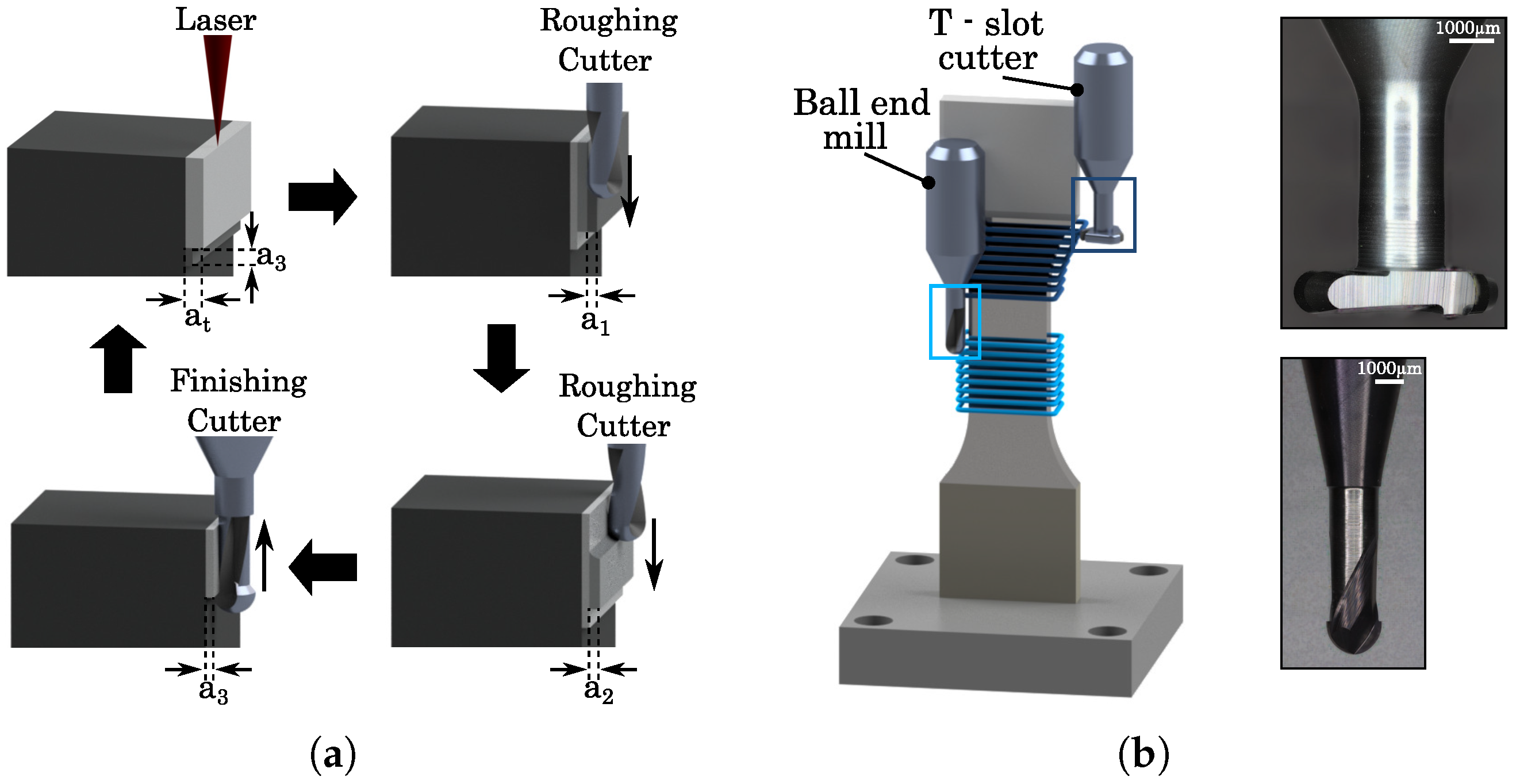
Figure 1. (a) Stepwise milling process for the hybrid manufacturing and (b) Milling of tensile components, using a Ball end mill and a T-slot milling cutter.
Jmmp 09 00378 g001
Figure 2. Temperature-time sequences for (a) solution treatment and hot isostatic pressing, and (b) hot isostatic pressing with solution treatment and double ageing for both processes.
Jmmp 09 00378 g002
Figure 3. Stress–strain diagram and UTS of different HIP-cycles in comparison to as-built components.
Jmmp 09 00378 g003
Figure 4. Wöhler-diagram and endurance limit ( σ ) of different HIP-cycles in comparison to as-built components.
Jmmp 09 00378 g004
Figure 5. Comparison of the static mechanical load behaviour of PBF-LB/M- and hybrid built components.
Jmmp 09 00378 g005
Figure 6. Evaluation of the dynamic mechanical load behaviour with a Wöhler-digram for PBF-LB/M- and hybrid built components.
Jmmp 09 00378 g006
Figure 7. Microstructural analysis of (a) as-built, (b) HT 1, and (c) HT 3 components, revealing the melting paths and the signs of grain boundaries (as-built) and different phase precipitations and grain boundary movement (HT 1, HT 3).
Jmmp 09 00378 g007
Table 1. Process parameters for the different milling steps.
InfeedZ-PitchSpindle SpeedFeed Rate
a n / μm a e , z / μm N/(1/min) v c /(mm/min)
Roughing1101504800240
Semi-finishing1101004800240
Finishing30809600240
Table 2. Chemical composition of Inconel 718 powder.
ElementNiCrNbMoTiAlCMnSiFe
Wt%50–5517–214.8–5.52.8–3.30.7–1.20.2–0.8<0.1<0.4<0.4balance
Table 3. Heat treatment cycles for the thermal post-processing of IN718.
Step 1Step 2DA
AB
HT 11150 °C/4 h/150 MPa980 °C/60 min720 °C/8 h, 620 °C/10 h
HT 21065 °C/90 min1150 °C/3 h/175 MPa720 °C/8 h, 620 °C/10 h
HT 31065 °C/90 min1150 °C/4 h/175 MPa720 °C/8 h, 620 °C/10 h
HT 41065 °C/90 min1150 °C/5 h/175 MPa720 °C/8 h, 620 °C/10 h
Disclaimer/Publisher’s Note: The statements, opinions and data contained in all publications are solely those of the individual author(s) and contributor(s) and not of MDPI and/or the editor(s). MDPI and/or the editor(s) disclaim responsibility for any injury to people or property resulting from any ideas, methods, instructions or products referred to in the content.