Article

Effects of Printing Angle, Infill Density and Cryogenic Pre-Treatment on the Tensile and Flexural Properties of FFF-Printed PLA

1
Faculty of Special Technology, Alexander Dubcek University of Trenčín, 911 06 Trenčín, Slovakia
2
Department of Mechanical Engineering, Faculty of Military Technology, University of Defence, 612 00 Brno, Czech Republic
*
Author to whom correspondence should be addressed.
J. Manuf. Mater. Process. 2025, 9(11), 365; https://doi.org/10.3390/jmmp9110365
Submission received: 5 October 2025 / Revised: 30 October 2025 / Accepted: 4 November 2025 / Published: 5 November 2025

Abstract

Additive manufacturing of polymer materials, also known as 3D printing, is becoming a key technology for the production of functional parts with the ability to customize the structure and properties according to the application requirements. Polylactide (PLA) is one of the most commonly used materials in this field due to its biodegradability, ease of processing, and adequate strength for lightweight functional components. An important factor that affects the resulting properties of parts is not only the filler structure and density but also the angle at which the material is deposited during the printing process. This article focuses on investigating the influence of the printing angle (0°, 30°, 60° and 90°) and the bulk density of the filler (20%, 40%, 60% and 80%) on the mechanical properties of PLA samples. Two series of samples were prepared—the first was subjected to direct mechanical tests, and the second series was first exposed to freezing conditions and then tested to evaluate the effect of freezing on the material behavior. The samples were tested for tensile strength according to ASTM D638 and for bending strength according to ASTM D790. The results showed that the highest values were achieved in tensile strength in the 60°/80% configuration with a strength of 39.27 MPa, which represents more than a twofold improvement over the weakest configuration (0°/20%–19.58 MPa). In the bending test, the best results were achieved by the 90°/80% sample with a strength of 58.89 MPa, approximately 18% higher than 0°/20%. Cryogenic treatment caused a deterioration of all monitored parameters, especially at low infill densities and at an angle of 0°, where the decrease in strength reached up to 10–13%. These results confirm that the combination of a higher printing angle and a higher infill density is key to optimizing the mechanical properties of PLA parts, while cryogenic treatment has a negative impact on their behavior.

1. Introduction

Additive manufacturing of polymers, also known as 3D printing, is one of the most advanced technologies in the field of materials engineering. Its main advantage is the ability to create parts with complex geometries, a high degree of customization and optimized material efficiency [1]. Among the most commonly used materials is polylactide (PLA), which is biodegradable and offers favorable mechanical properties [2]. Despite these benefits, its limitations remain higher brittleness and lower thermal stability, which leads to the need to investigate printing parameters and structural modifications to increase mechanical reliability and product durability [3]. Almonti et al. investigated the mechanical and functional behavior of polyethylene terephthalate glycol-modified (PETG) produced by FFF (Fused Filament Fabrication), emphasizing its excellent strength, chemical resistance, and thermal stability. A distinctive feature of PETG identified in their study is its shape-memory effect, which allows the material to return to its original shape when heated above the glass transition temperature, enabling the fabrication of adaptive and recoverable components. These properties make PETG an attractive alternative to PLA for advanced additive manufacturing applications requiring durability and functional responsiveness [4]. One of the most studied factors in the field of FFF technology is the infill geometry and density. Agrawal et al. demonstrated that different infill patterns significantly affect the tensile strength, while optimal combinations can significantly improve mechanical resistance [5]. Khaliq et al., using experimental and numerical analyses, found that geometries with increased layer overlap, such as hexagonal or ribbed structures, provide higher strength than traditional linear arrangements [6]. Similarly, Turaka et al. pointed out the reduced strength at low filler density due to the formation of gaps between the fibers, while too high a density leads to internal stresses and delamination [7]. dos Reis et al. emphasized the need to find a compromise between strength, weight and efficiency when choosing the density and shape of the filler [8]. The printing angle and the orientation of the layers are also important parameters. Naveed demonstrated that the orientation of the fibers relative to the loading axis has a significant effect on the impact toughness and anisotropy of the material [9]. Guessasma showed that changes in the orientation of the layers can lead to differences in tensile strength and elastic modulus of up to tens of percent [10]. According to Fekiač et al., proper orientation is critical, especially for continuous fibers, where the angle to the force determines the effective stress transfer [11]. Dziewit et al. added that appropriate orientation, together with the density of the filler, fundamentally changes the tensile and bending behavior [12]. Further research has expanded the investigation to include new reinforcements and hybrid approaches. Hsueh et al. report that the integration of carbon fibers into the PLA matrix increases the strength and elastic modulus, making the material applicable in areas with higher loads [13]. Chicos et al. point out the growing trend of using automated processes and combinations of natural fibers, such as flax or Cordenka, which bring favorable strength-to-weight ratios and environmental benefits [14]. Qayyum and Kohutiar have documented in detail that such natural fibers can serve as an alternative to classic synthetic reinforcements [15,16]. Orellana-Barrasa et al. have also shown that increasing the filler density in PLA/CF composites improves not only the strength but also the fatigue resistance [17]. In addition to the structural parameters themselves, the literature also focuses on the optimization of process conditions and predictive modeling. Turaka et al. used numerical simulations to predict the mechanical behavior of PLA composites and showed that the right combination of printing parameters allows for more precise control of fatigue resistance [7]. Similar studies use statistical approaches to model the dependence between infill, printing angle and mechanical properties, which is a tool for rapid optimization of part design without extensive testing [8,12].
Based on the knowledge to date, it can be concluded that the mechanical properties of PLA parts are the result of a complex interaction between the density and shape of the infill, the orientation of the fibers, and possibly the selected reinforcement. Despite a wide range of studies, relatively little attention remains paid to the combined effect of printing angle and infill density in the context of specific environmental conditions, such as cryogenic treatment.
This study is a continuation of the scientific work of Fekiač et al., which analyzed the influence of infill geometry and density on the mechanical properties of 3D-printed PLA parts [1]. Following on from these results, current research focuses on another significant parameter—printing angle—and its combined effect with bulk density of the filler and freeze-drying.
The aim of this work is therefore to analyze the influence of the printing angle (0°, 30°, 60° and 90°) and four different infill densities (20%, 40%, 60% and 80%) on the mechanical properties of PLA samples. Two series of specimens—as-printed and cryogenic pre-treated—were investigated, with the latter subjected to cryogenic treatment at a temperature of −80 °C. The tensile strength, yield strength, elastic modulus and flexural strength parameters were evaluated according to the relevant ASTM standards. The results provide new insights into the combined effect of geometric parameters and environmental conditions, which is of importance for the design and applications of 3D-printed parts in practice.
Although many studies have investigated the effect of infill density or raster angle separately, the combined influence of printing angle and infill density under cryogenic pre-treatment has not been sufficiently explored. Therefore, this study focuses on evaluating the mechanical behavior of PLA parts printed under different orientations and densities before and after cryogenic treatment. The main objective is to clarify how these parameters affect tensile and flexural strength and to provide guidelines for optimizing the design of FFF-printed PLA components.

2. Materials and Methods

The aim was to evaluate the influence of printing angle, bulk density of the filler and subsequent freezing on the mechanical properties of PLA samples manufactured by FFF (Fused Filament Fabrication) technology. The procedures were designed to ensure reproducibility of the experiments and comparability of the results. The following subsections detail the materials used, 3D printing parameters, sample conditioning conditions and tensile and bending test procedures according to the relevant ASTM standards.

2.1. Materials

Polylactide filament (PLA, Bambulab, 1.75 mm) was used to prepare the samples, which were dried at 20 °C for 24 h before printing. All tests were performed under laboratory conditions at 23 ± 2 °C and 50 ± 5% relative humidity. Technical details of the used material, printing equipment, process settings and sample configuration are given in Table 1 for clarity and to ensure reproducibility.

2.2. Preparation of Test Samples (FFF)

Detailed material and processing parameters are summarized in Table 1. The printing conditions, including nozzle temperature, bed temperature, and layer height, followed the manufacturer’s default settings for PLA. The geometry of the tensile samples was according to ASTM D638 (type I, Figure 1); the bending samples were according to ASTM D790 (three-point diagram, Figure 2). For each combination of printing angle and infill density, 5 tensile and 5 bending samples were prepared. The same number of specimens was used for both the as-printed and cryogenic pre-treated series to allow for a direct comparison of the results. Samples that showed visible manufacturing defects (e.g., underfilling or deformation) were discarded and replaced with new ones before testing.
For each configuration of printing angle and infill density, five specimens were prepared for tensile testing and five for flexural testing, resulting in a total of 320 samples (160 as-printed and 160 cryogenically pre-treated).

Definition of Printing Angle and Filling Variants

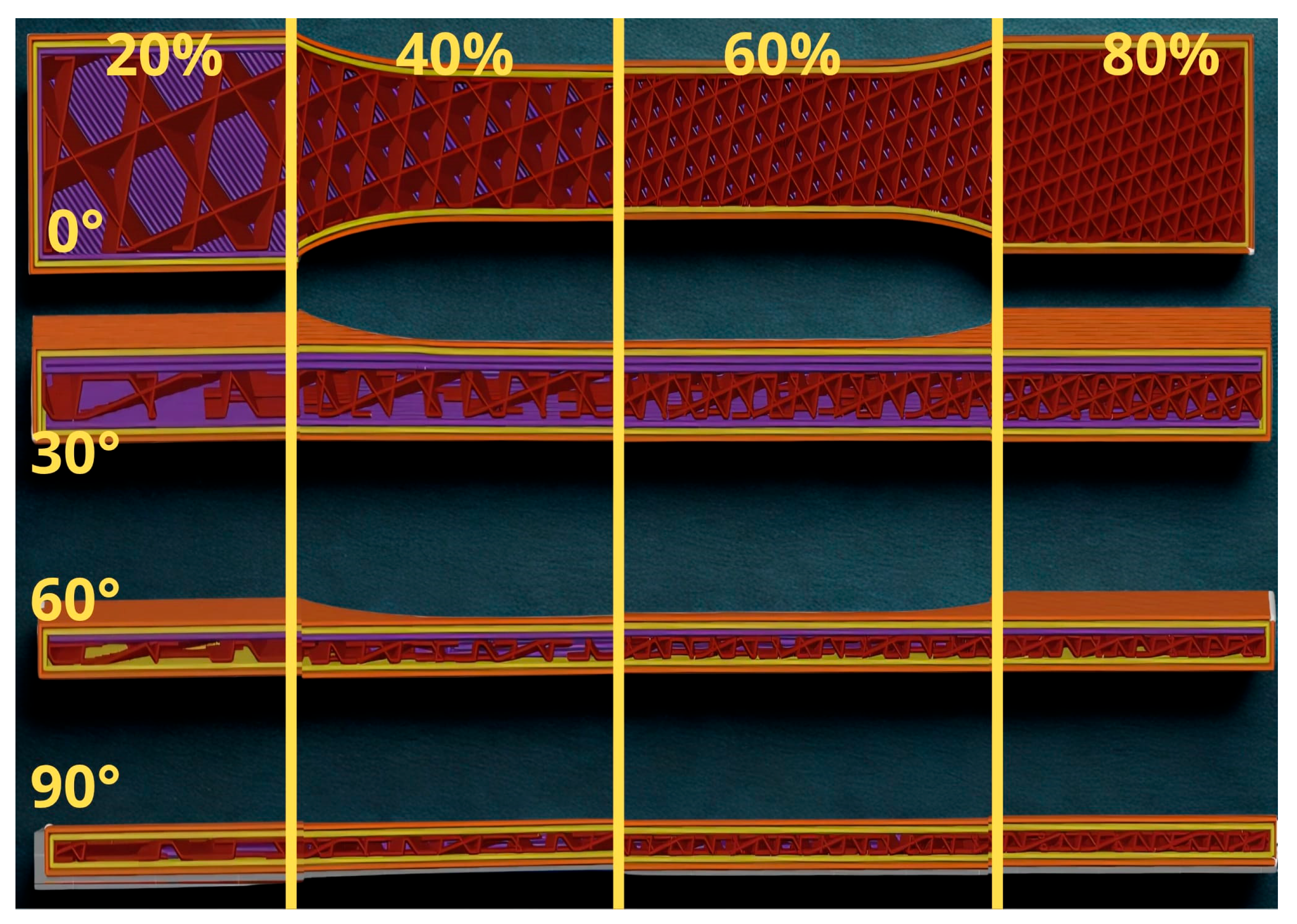
The test samples were manufactured using FFF technology from PLA material. The influence of the printing angle and the bulk density of the filler was considered when preparing them. The samples were oriented to the substrate at four different angles: 0°, 30°, 60° and 90° Figure 3 and Figure 4. The aim was to determine how the set printing angle would affect the strength and flexibility of the printed parts.
For each of these angles, four different infill levels were produced with bulk densities of 20%, 40%, 60% and 80%, as shown in Figure 5. This created a series of samples with different internal structures, which allowed the combined effect of density and printing orientation to be evaluated. In all cases, the same type of infill–cubic–was used to eliminate the influence of different geometries and the results only reflected the effect of the parameters under study. The samples thus prepared were then divided into two series: the first was subjected to mechanical tests directly after printing, while the second series was cryogenic pre-treated before testing and subsequently tested using the same procedure.

2.3. Conditioning and Cryogenic Treatment

After printing, the samples were divided into two series according to subsequent processing:
As-printed series–these samples were tested directly after printing, without additional conditioning or pre-treatment.
Cryogenic pre-treated series–the samples were immediately sealed in airtight plastic bags after printing to prevent moisture condensation on their surface during freezing. They were then stored in a freezer at −80 °C for 24 h. Before the mechanical tests themselves, they were allowed to warm up to laboratory temperature for 24 h to eliminate temperature differences and ensure comparable testing conditions.
This procedure allowed for a comparison between the mechanical properties of as-printed specimens and those that had undergone cryogenic pre-treatment followed by stabilization at room temperature.
The printing angles of 0°, 30°, 60°, and 90° were selected to cover the most representative orientations observed in practical FFF applications, ranging from longitudinal to transverse layer alignment. Similarly, the chosen infill densities of 20%, 40%, 60%, and 80% allow the evaluation of a wide spectrum of structural compactness, from lightweight porous structures to highly dense configurations. This combination of parameters enables a comprehensive assessment of both anisotropy and material compactness effects on mechanical performance.

2.4. Tensile Test

Tensile tests were performed on a universal testing machine (ZWICK Z100/TL3S Zwick GmbH & Co. KG, Ulm, Germany) (equipped with a force sensor with a capacity of [100 kN]. The geometry of the test samples corresponded to the ASTM D638 standard. The test speed of the crosshead was set according to the requirements of the standard at 5 mm/min.
During testing, the stress-elongation dependence was continuously recorded. The tensile modulus of elasticity was determined from the linear part of the curve, and the yield strength (offset 0.2%) and maximum tensile strength were subsequently evaluated.
It is well known that parts produced by FFF exhibit anisotropic mechanical behavior due to the layer-by-layer deposition process. The bonding between adjacent filaments and the orientation of the deposited layers determine the anisotropic response under tensile and bending loads. Therefore, the selected printing angles (0°, 30°, 60°, and 90°) were chosen to represent the full range of anisotropic behavior from parallel to perpendicular alignment with respect to the loading direction.

2.5. Bending Test

Bending tests were performed on the same test rig according to ASTM D790 using a three-point bend. The test samples were placed on supports with a distance of 64 mm, which was determined as 16 times the sample thickness (L = 16 × 4). The crosshead speed was calculated in accordance with the standard based on the sample thickness and the support distance of 2 mm/min. The bending strength and bending modulus were determined from the measured data.

3. Results

3.1. Tensile Test–Series of As-Printed Samples

3.1.1. Yield Strength–As-Printed Samples

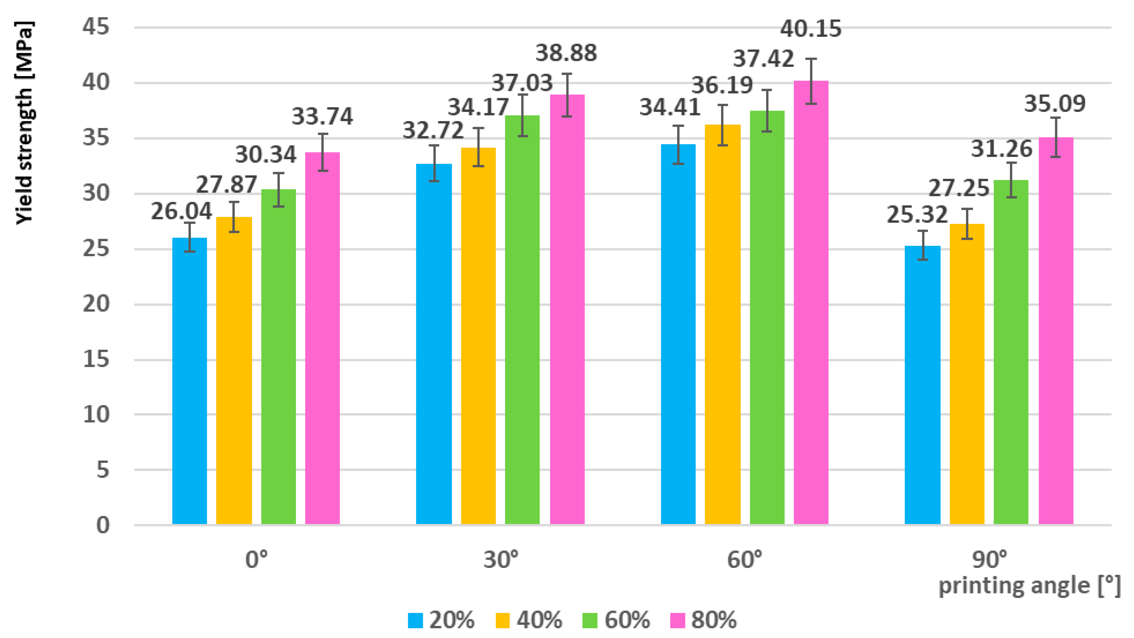
The results of experimental measurements (Figure 6) confirmed that the yield strength of the studied samples was significantly influenced by both the percentage density of the filling and the orientation angle during 3D printing. With increasing filling density, a systematic increase in yield strength values was observed, which indicates a positive effect of a higher proportion of material in the structure on the mechanical response. The lowest measured value was recorded for samples with a layer orientation of 0° and 20% filling (26.04 MPa), which represents a limiting case for the combination of minimum density and an orientation unfavorable for load transfer.
On the contrary, the maximum yield strength value was achieved for samples with an orientation angle of 60° and 80% filling, where a value of 40.15 MPa was measured. This result indicates a synergistic effect of the optimal orientation of the printing layers and the increased proportion of filler, which leads to a more efficient stress distribution and higher resistance to plastic deformation.
The overall trend of the yield strength development showed that increasing the angle from 0° to 60° contributed to a gradual improvement in mechanical properties. However, at a layer orientation of 90°, the measured values decreased (e.g., 35.09 MPa at 80% filler), which can be interpreted as a consequence of a less favorable fiber orientation in relation to the applied load and an increase in the probability of interlaminar failure.

3.1.2. Tensile Strength–As-Printed Samples

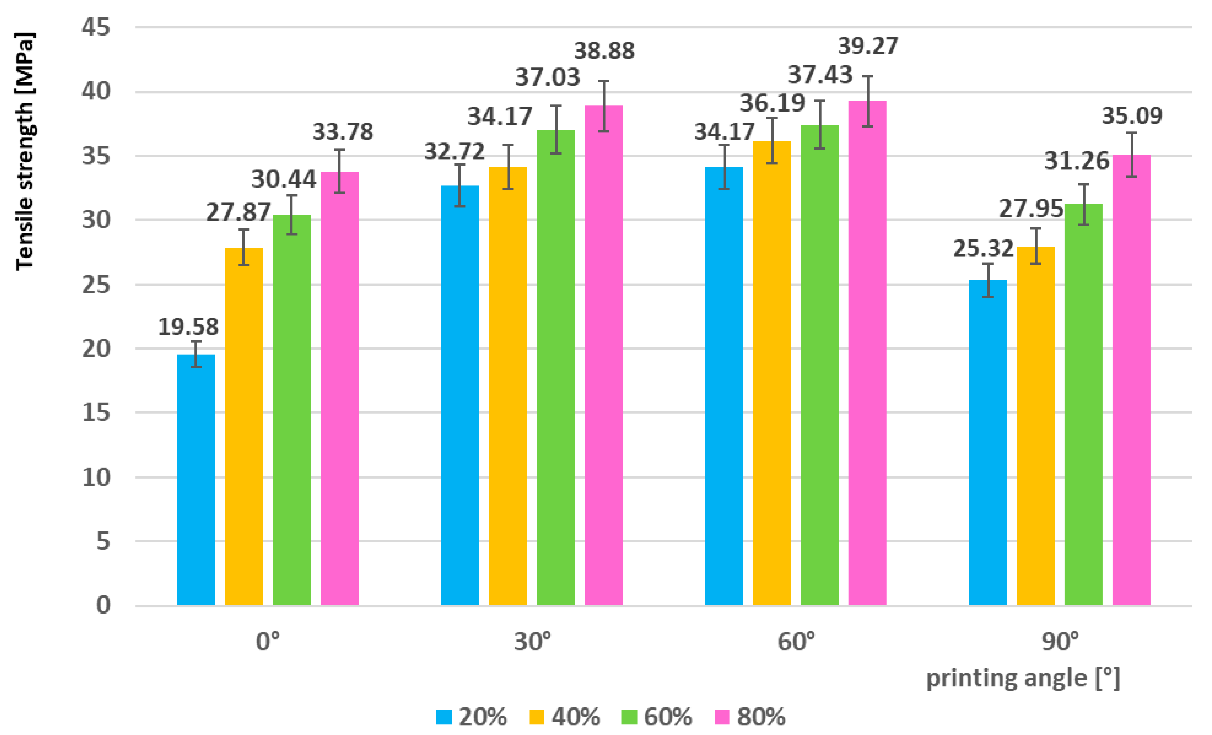
A similar trend was also identified in the tensile strength evaluation, see Figure 7. The lowest measured value was recorded for samples manufactured with an orientation angle of 0° and 20% infill (19.58 MPa), which represents the limiting combination of low density and unfavorable orientation in relation to the applied load. Conversely, the maximum tensile strength was achieved for samples printed at an angle of 60° and 80% infill (39.27 MPa), which indicates the synergistic effect of optimal fiber orientation and higher infill content on more efficient mechanical load transfer. Overall, it was observed that the tensile strength increased with increasing infill density, with the most significant increase being recorded when going from 20% to 60%. This phenomenon can be explained by the increased compactness of the material structure and the reduction in the proportion of internal voids, which leads to the elimination of weak spots in the microstructure. At 90° orientation, a decreasing tendency was again observed (35.09 MPa at 80% filling), which is related to a less favorable orientation of the layers with respect to the applied stresses and an increased probability of interlaminar failure.

3.1.3. Elastic Modulus–As-Printed Samples

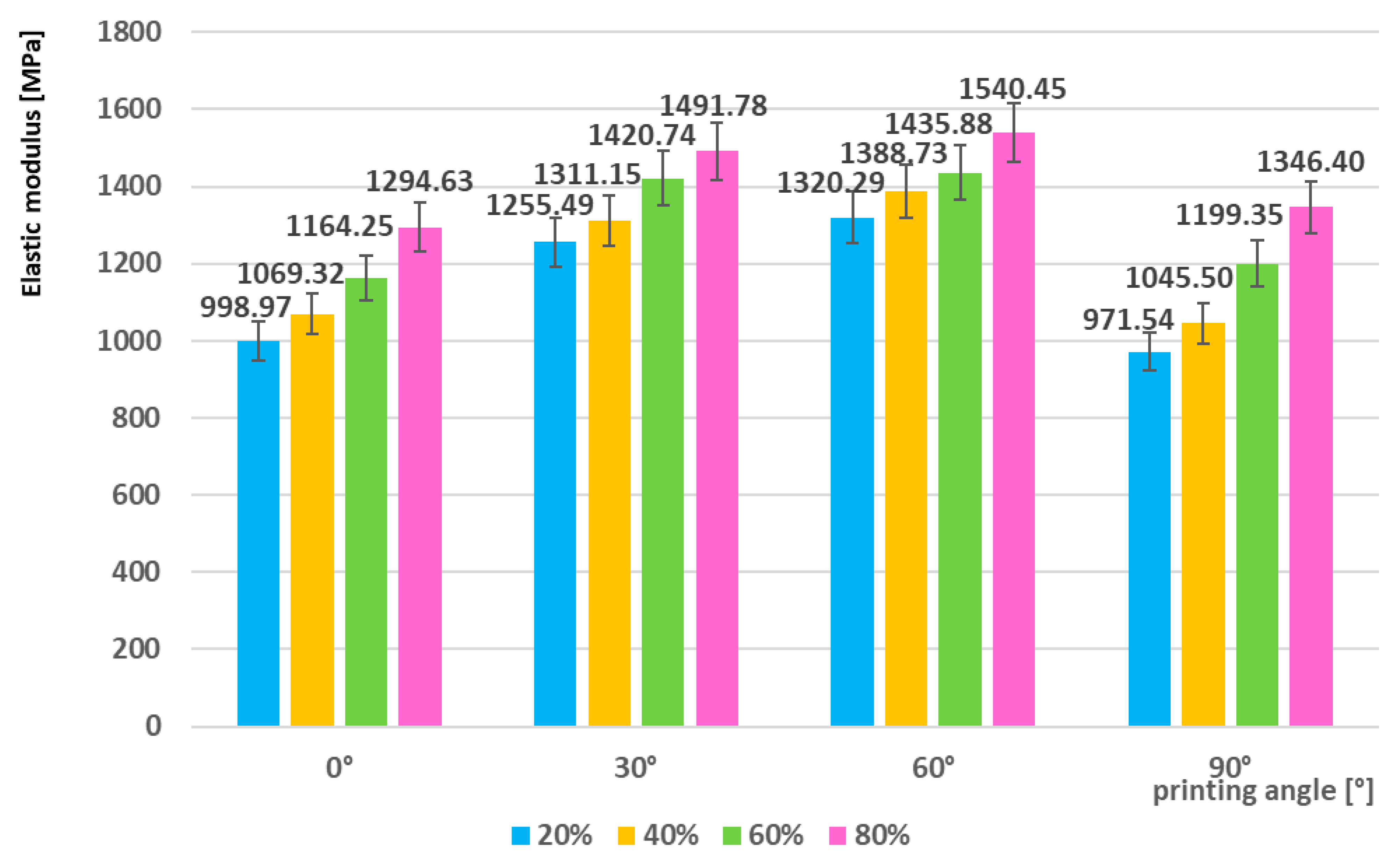
The elastic modulus of the investigated samples ranged from 998.97 MPa (angle 0°, 20% filling) to 1540.45 MPa (angle 60°, 80% filling). The results (Figure 8) clearly showed that increasing the filling density contributes to a significant increase in the stiffness of the material, with the most significant difference being recorded between the values of 20% and 60%, which confirms the importance of reducing internal pores and increasing the compactness of the structure. The effect of the printing angle turned out to be similar to that of the strength-the highest values of the elastic modulus were achieved at angles of 30° and 60°, which represent the optimal arrangement of the fibers in relation to the applied load. Conversely, at 90°, a decrease was recorded (1346.40 MPa at 80% infill), which, although lower than the maximum at 60°, was still higher than at 0°. This result suggests that the orientation of the layers in the direction perpendicular to the load leads to less efficient stress transfer, although the higher infill density partially compensates for this adverse effect.

3.2. Tensile Test–Cryogenic Pre-Treated Sample Series

3.2.1. Yield Strength–Cryogenic Pre-Treated Sample

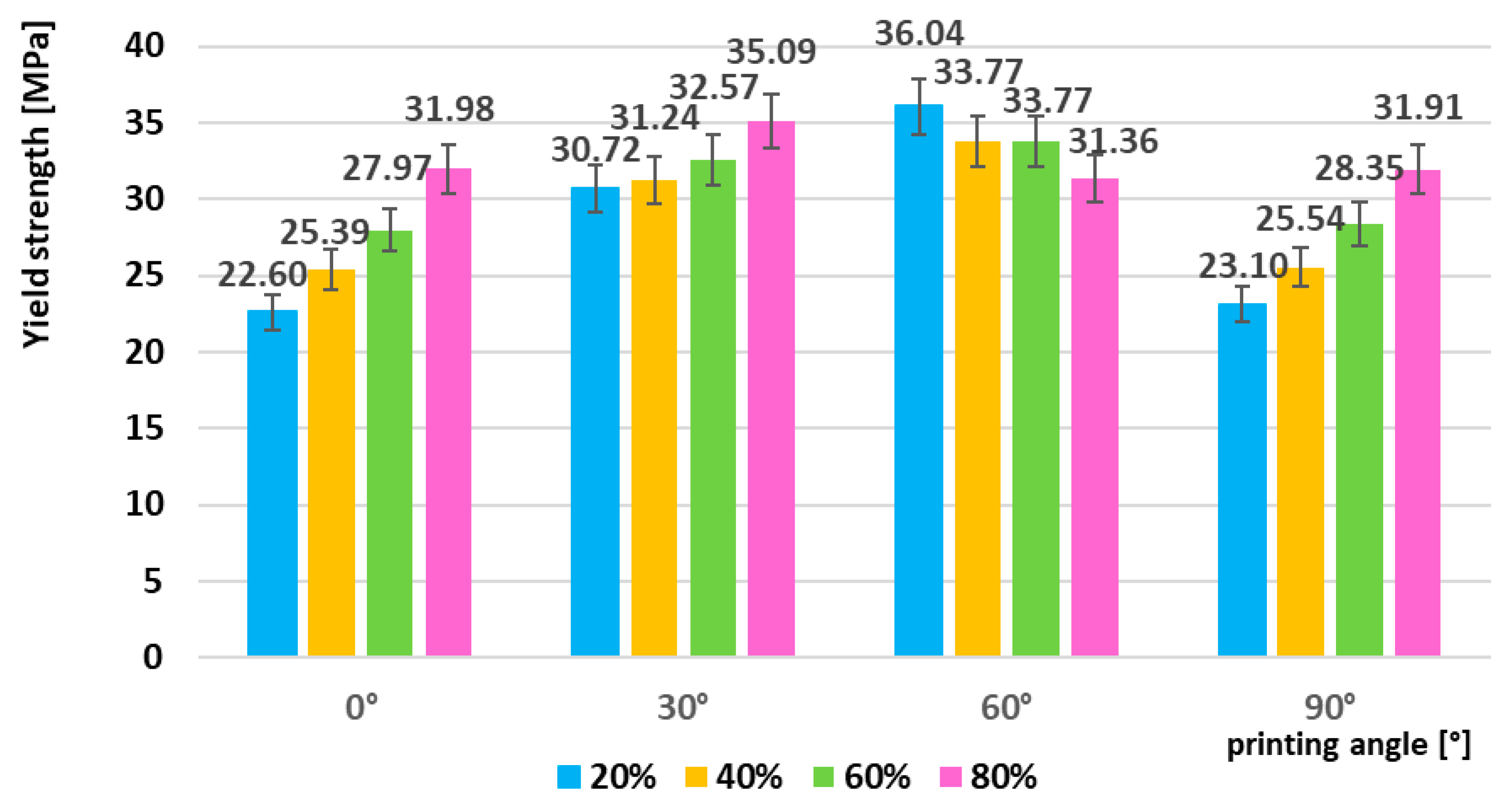
The lowest yield strength was recorded for samples manufactured with an orientation angle of 0° and 20% infill (22.60 MPa). On the contrary, the maximum value was measured for samples with an angle of 60° and 20% infill (36.04 MPa) (Figure 9). Similarly to the as-printed samples, a positive effect of higher infill density on increasing the yield strength was also observed here, but the differences between the individual infill levels were significantly less pronounced. At the 90° layer orientation, a decreasing tendency was again observed, with the highest value at 80% infill reaching 31.91 MPa, which was lower than the maximum recorded at 60°.
The fact that these samples were cryogenic pre-treated before testing played a significant role in their mechanical response. The low temperature reduced the mobility of the polymer chains and shifted the material towards the glassy region, which resulted in increased brittleness and limited plastic deformation. For this reason, the sensitivity to the filler density was lower, while the influence of the fiber orientation, which determined the efficiency of stress transfer, was more significant. In other words, the frost caused structural factors such as the printing angle to have a more significant impact on the mechanical behavior than the filler density itself.

3.2.2. Tensile Strength–Cryogenic Pre-Treated Samples

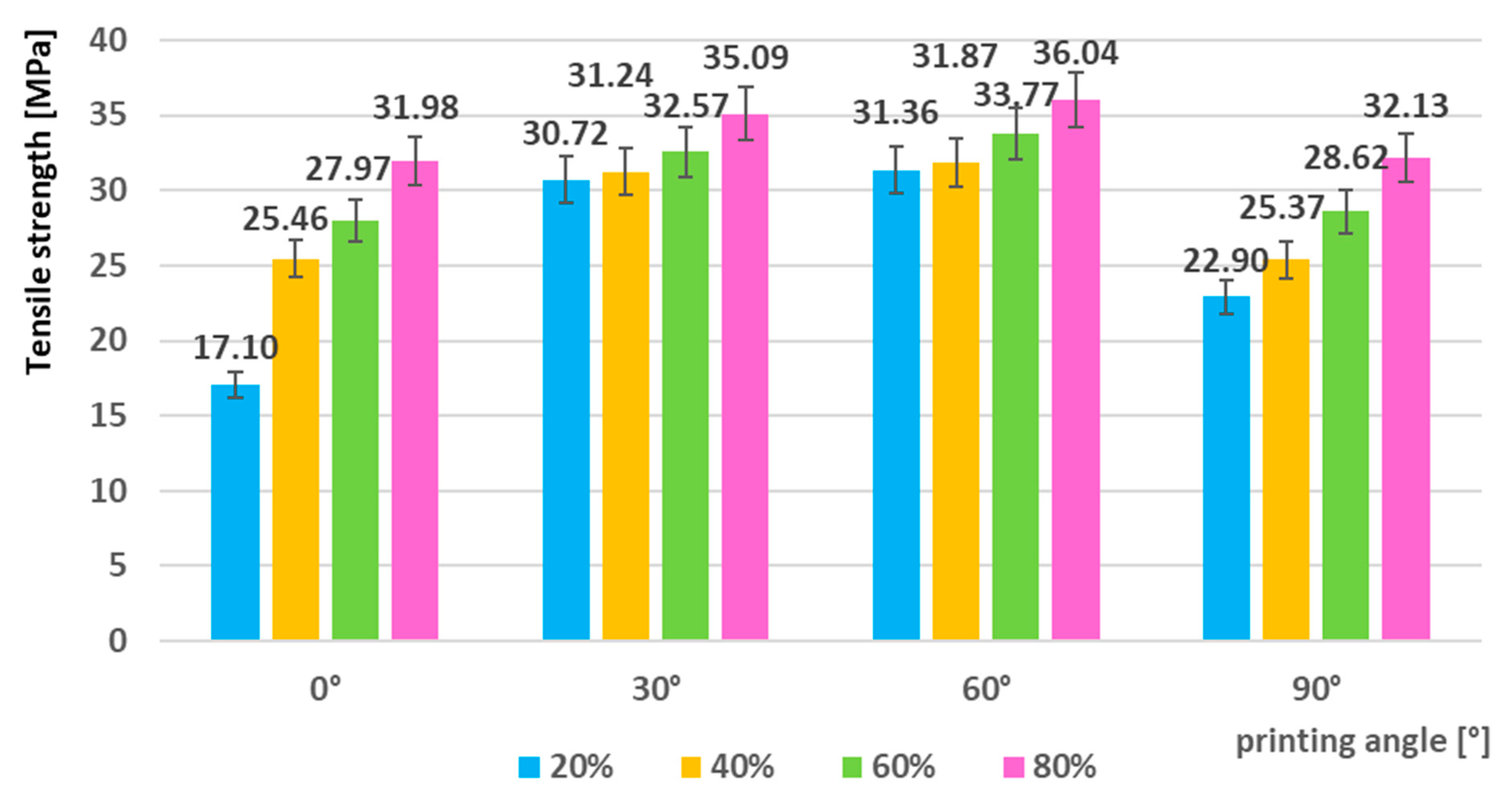
The lowest tensile strength value was measured for samples with an orientation angle of 0° and 20% infill (17.10 MPa), which is even lower than the as-printed series (Figure 10). This result indicates a significant negative effect of freezing, which reduces the mobility of polymer chains and increases the brittleness of the material. On the contrary, the highest strength was achieved for samples printed at an angle of 60° and 80% infill (36.04 MPa), which again confirms the synergistic effect of optimal fiber orientation and higher infill density. The general trend showed that the tensile strength increased with increasing infill density, with the most significant improvement being recorded at angles of 30° and 60°. At 90° orientation, a decreasing tendency was again observed (32.13 MPa at 80% filling), which indicates a less favorable arrangement of the layers in relation to the applied tensile load.
The fact that the samples were cryogenic pre-treated before the tests significantly affected their mechanical behavior. Under the influence of low temperatures, the polymer gets closer to the glassy state, which reduces its ability to plastically deform and increases the probability of brittle fracture. This effect was especially evident at low filling density and unfavorable orientation, where the strength was significantly reduced compared to as-printed samples. At the same time, it was shown that higher filling density and optimal orientation (30° and 60°) can partially compensate for the negative effect of freezing, since these configurations allow for more efficient stress transfer even with reduced material toughness.

3.2.3. Elastic Modulus–Cryogenic Pre-Treated Samples

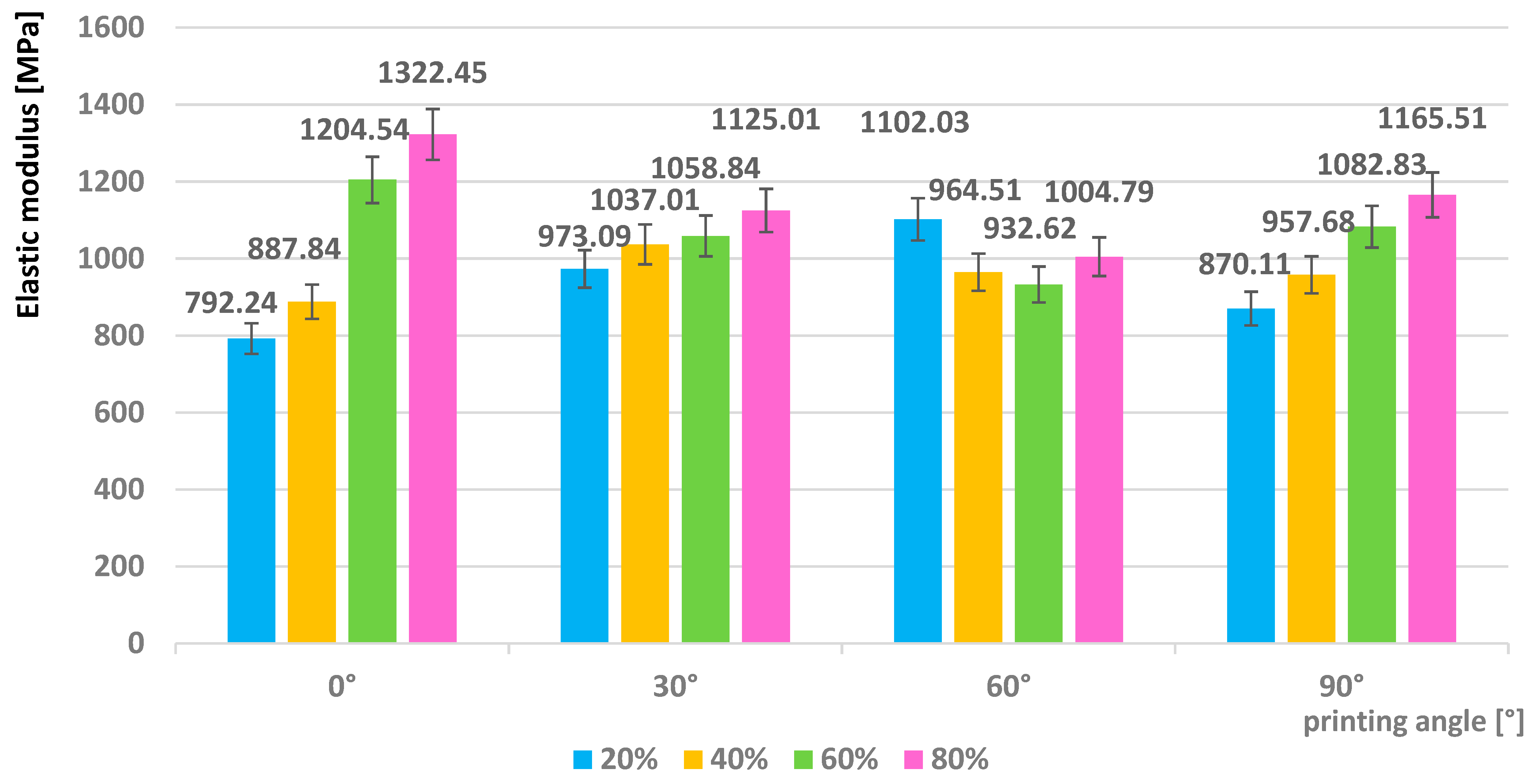
The elastic modulus (Figure 11) of the examined samples ranged from 792.24 MPa (0° angle, 20% filling) to 1322.45 MPa (0° angle, 80% filling). In contrast to the results of the as-printed series, the maximum values were not reached at the 60° angle, but at the 0° orientation with the highest filling density. At the 30° and 60° angles, the values were lower compared to the as-printed samples, which indicates that the effect of the layer orientation was less pronounced in the cryogenic pre-treated samples. At the 90° angle, the modulus reached a maximum of 1165.51 MPa, which confirms the slightly decreasing trend typical for this orientation.
A significant factor was the fact that the samples were exposed to low temperatures before the tests. Freezing caused a decrease in the mobility of the polymer chains and thus an increase in the stiffness of the material, which explains the higher values measured at the 0° orientation. However, at the same time, the ability of the material to effectively transmit stress at angular orientations (30° and 60°), which under normal conditions provided optimal results, was limited. This effect can be interpreted as a consequence of the material moving closer to the glassy state, where a more rigid behavior is applied, but at the same time the advantage of favorable anisotropy of the layers is lost.
The obtained results therefore show that in the cryogenic pre-treated samples the filler content itself had a more dominant effect than the orientation, with the frost “suppressing” the differences between the angles and highlighting the effect of the higher density.

3.3. Comparison of As-Printed and Cryogenic Pre-Treated Series

When comparing the tensile test results of as-printed and cryogenic pre-treated samples, it was shown that cryogenic treatment had a generally negative effect on the strength and stiffness of the material.

3.3.1. Yield Strength

In the as-printed series, the samples reached their maximum yield strength at an angle of 60° and 80% filling (40.15 MPa), while in the cryogenic pre-treated series the highest value was lower (36.04 MPa). The difference was even more pronounced at low filling densities–for example, at 0° and 20% filling, the yield strength decreased from 26.04 MPa (as-printed) to 22.60 MPa (cryogenic pre-treated). This phenomenon can be explained by the fact that freezing causes a decrease in the mobility of polymer chains and thus their ability to redistribute stress, which leads to an earlier onset of plastic deformation.

3.3.2. Tensile Strength

A similar trend was observed for tensile strength. In the as-printed series, the maximum strength was achieved at an angle of 60° and 80% infill (39.27 MPa), while in the cryogenic pre-treated series it was only 36.04 MPa under the same conditions. The largest difference was observed for samples with low density and unfavorable 0° orientation, where the strength decreased from 19.58 MPa (as-printed) to 17.10 MPa (cryogenic pre-treated). These results indicate that cryogenic treatment reduces the toughness of the material and promotes brittle fracture, especially for samples with a high proportion of voids and weaker bonding between the layers.

3.3.3. Elastic Modulus

In the case of the elastic modulus, interesting differences were shown. While the samples from the as-printed series reached maximum values at 60° and 80% filling (1540.45 MPa), in the cryogenic pre-treated series the highest stiffness was already evident at 0° and 80% filling (1322.45 MPa). This shift in the maximum suggests that the cryogenic treatment could have negatively affected the stress transfer mechanism at optimal orientation angles (30–60°), thereby suppressing the anisotropic advantage characteristic of as-printed samples.
Overall, it can be stated that the samples from the as-printed series showed higher strength and stiffness in all monitored parameters compared to the cryogenic pre-treated series. The cryogenic treatment caused a decrease in the values, with the difference being most pronounced at low filling density and 0° orientation. The best mechanical properties were achieved in both series at an angle of 60° and high filling density (80%), while a decreasing tendency was repeatedly confirmed at 90°. From the point of view of microstructural action, the effect of freezing can be interpreted as a decrease in polymer chain mobility, an increase in brittleness and a suppression of the beneficial effect of optimal layering at higher orientation angles.

3.4. Bending Test–Series of As-Printed Samples

3.4.1. Flexural Modulus–As-Printed Samples

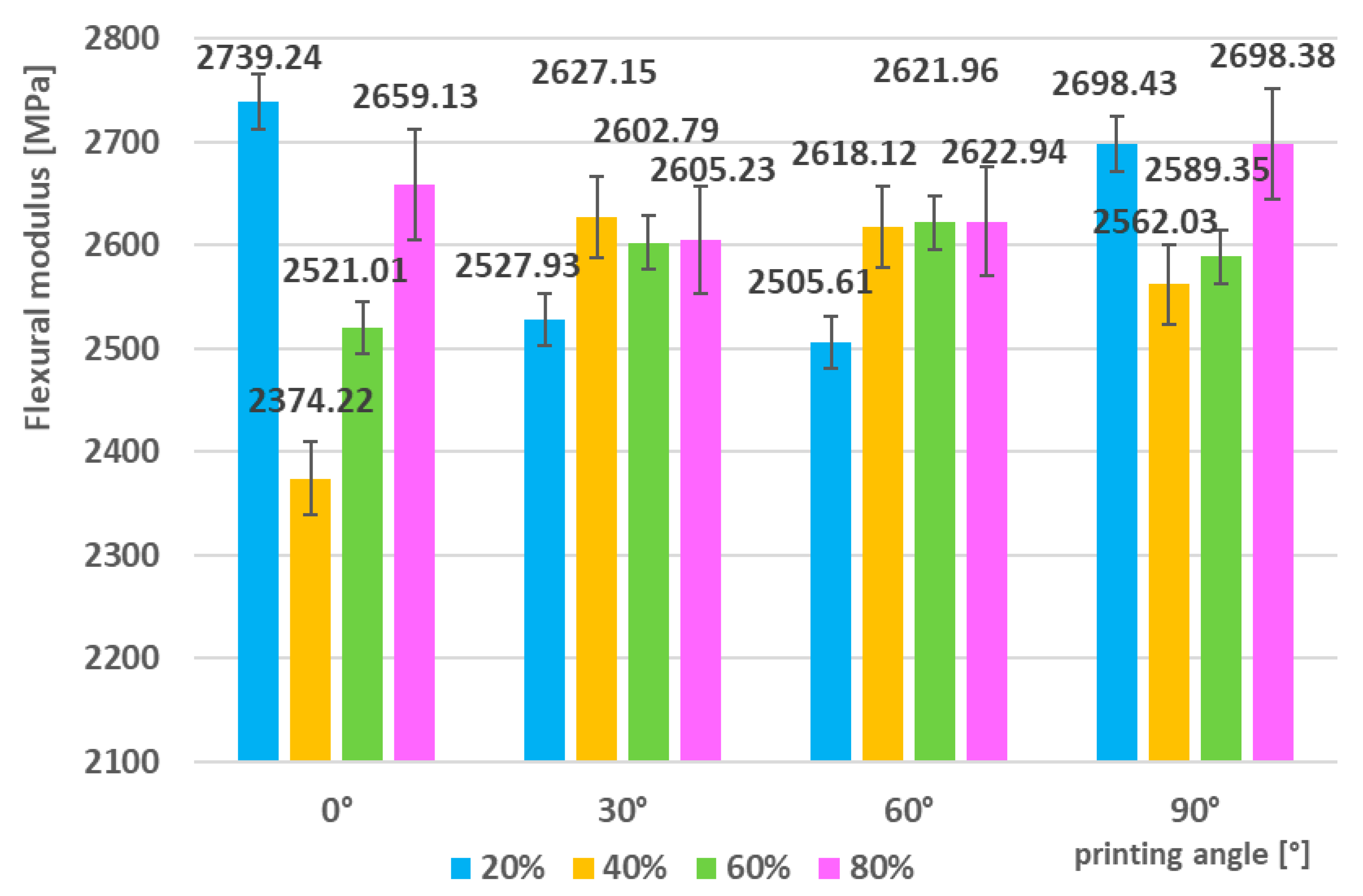
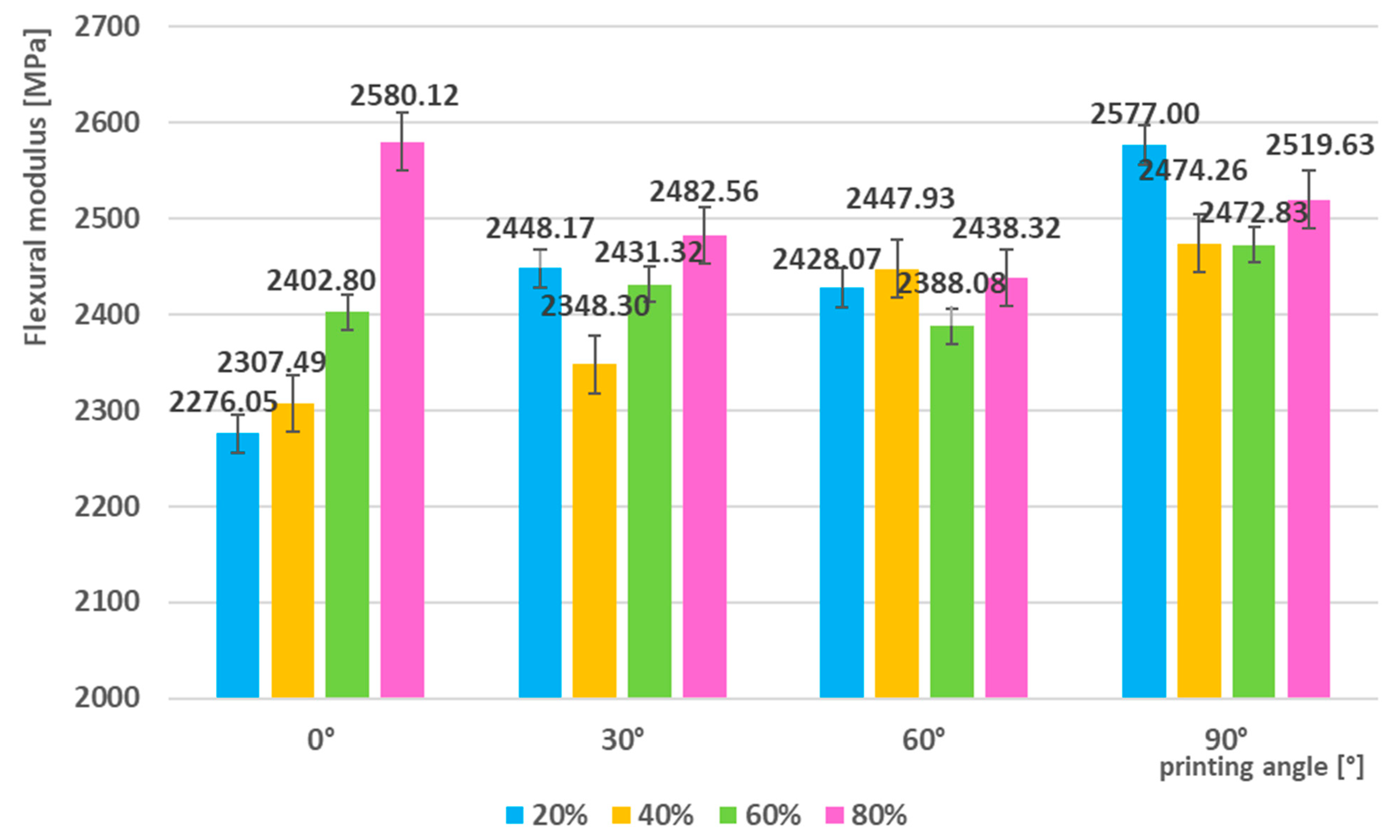
The values of the flexural modulus of elasticity can be seen in Figure 12 and ranged from 2374.22 MPa (0° angle, 40% infill) to 2739.24 MPa (0° angle, 20% infill). In contrast to the tensile test results, a clear trend of increasing stiffness with increasing infill density was not confirmed in this case. The highest values were paradoxically recorded for samples with 0° orientation, even at a relatively low density (20%).
At higher layer orientation angles (30–90°), the measured values ranged in a narrower interval, approximately between 2500 and 2700 MPa, which indicates that in flexural stress, the layer orientation does not play such a fundamental role as in tensile tests. Overall, it was shown that the differences between the individual parameter combinations were relatively small and that in the case of the flexural modulus, the geometry and integrity of the filler structure itself play a more dominant role than its percentage density or printing angle.
This result points to a different stress transfer mechanism in the flexural test, where the material is loaded by a combination of tensile and compressive stresses in different layers. The resulting modulus thus depends more on the overall macrostructural integrity of the sample than on the details of the anisotropic arrangement of the layers, which are more pronounced in purely tensile stress.

3.4.2. Flexural Strength–As-Printed Samples

The flexural strength showed a gradual increase with increasing printing angle. The lowest values were measured for samples with 0° orientation, where they were approximately 50 MPa (e.g., 49.86 MPa at 40% infill) (Figure 13). With increasing orientation angle, there was a systematic improvement, with maximum values being reached at 90°, where the strength exceeded 58 MPa (58.89 MPa at 80% infill).
The infill density had a positive effect on the results, but this effect was less pronounced than the printing angle. The difference between the minimum (20%) and maximum infill density (80%) was approximately 3–4 MPa, indicating that fiber orientation is a more decisive factor for flexural strength than the infill compactness itself.
These results indicate that the stress transfer mechanism in the bending test is strongly influenced by the orientation of the layers with respect to the bending moment. At 0°, the layers are aligned parallel to the direction of the applied stress, which leads to earlier delamination and lower strength values. Conversely, at 90°, the layers are oriented perpendicular to the bending direction, which improves the resistance to crack initiation and propagation, as reflected by the highest measured values.

3.5. Bending Test–Cryogenic Pre-Treated Sample Series

3.5.1. Flexural Modulus-Cryogenic Pre-Treated Sample

The flexural modulus values (Figure 14) ranged from 2276.05 MPa (0° angle, 20% infill) to 2580.12 MPa (0° angle, 80% infill). The highest values were recorded for samples with 0° orientation and high infill density, while for other angles the modulus ranged in a narrower interval of 2388–2577 MPa. The effect of printing angle appeared to be less dominant in this series, with differences between samples oriented at 30°, 60° and 90° being relatively small. Compared to the as-printed series, cryogenic treatment was shown to lead to a decrease in the maximum values of the modulus. This effect can be explained by the limitation of the mobility of polymer chains at low temperatures, which causes higher brittleness and a lower ability to effectively transmit stress under bending stress. The decrease in the maximum compared to the as-printed series also indicates that frost suppressed the beneficial effect of optimal fiber arrangement, which was more pronounced in as-printed samples. Overall, the results indicate that in the bending test of cryogenic pre-treated samples, the filler content played a more dominant role than the orientation angle itself, but the absolute values were lower than in the case of as-printed samples.

3.5.2. Flexural Strength–Cryogenic Pre-Treated Samples

The lowest flexural strength was recorded for samples with 0° orientation and low infill density (41.11 MPa), while the maximum values were achieved at 90° orientation, where the strength reached up to 51.39 MPa (80% infill) (Figure 15). Overall, the trend of gradual increase in strength with increasing printing angle was confirmed; however, the differences between 20% and 80% infill were relatively small, ranging up to 4 MPa. At angles of 30° and 60°, the flexural strength ranged in the range of 45–50 MPa, which is lower than the values achieved in the as-printed series. This decrease suggests that cryogenic treatment negatively affected the stress transfer mechanism at these orientations. Low temperatures reduce the mobility of polymer chains and increase the brittleness of the material, thereby reducing the ability of the layers to effectively withstand the combined tensile-compressive stress typical of a bending test. In general, it can be stated that cryogenic treatment caused a decrease in bending strength especially at medium orientation angles (30° and 60°), while at 90° the samples retained relatively high resistance. This confirms that in cryogenic pre-treated samples the orientation of the layers is a more decisive factor than the density of the filler itself, with higher values being achieved when the layers act perpendicular to the bending direction.

3.6. Comparison of As-Printed and Cryogenic Pre-Treated Series–Bending Test

When comparing the results of bending tests of as-printed and cryogenic pre-treated samples, it was confirmed that cryogenic treatment had a predominantly negative effect on mechanical properties.

3.6.1. Flexural Modulus

In the as-printed series, the samples reached a maximum value of the elastic modulus at 0° orientation and 20% filling (2739.24 MPa), while in the cryogenic pre-treated series the maximum was lower, 2580.12 MPa (0°/80%). At higher orientation angles (30–90°), the differences between the series were smaller, but, in general, the values in the as-printed series ranged approximately 50–150 MPa higher. This shift suggests that the cryogenic treatment caused a slight decrease in the stiffness of the material, which can be attributed to the reduction in chain mobility and increased brittleness of the polymer.

3.6.2. Flexural Strength

The flexural strength reached a maximum value of 58.89 MPa (90°/80%) in the cryogenic pre-treated series, while it was only 51.39 MPa (90°/80%). The difference of approximately 7.5 MPa represents a noticeable decrease after cryogenic treatment. The largest differences between the series were recorded at lower printing angles-for example, at 0° and 20% infill, the strength decreased from 50.01 MPa as-printed) to 41.11 MPa (cryogenic pre-treated). This confirms that frost most significantly affected the samples with lower density and unfavorable layer orientation. In general, it can be stated that the samples from the as-printed series achieved higher values of both the modulus of elasticity and flexural strength in all parameter combinations. The cryogenic treatment caused a systematic decrease in both monitored characteristics, with the greatest impact observed at low infill density and 0° orientation. The best results in both series were achieved by samples with a 90° orientation, but even here the values of the as-printed series were clearly higher.

3.7. Microscopic Analysis

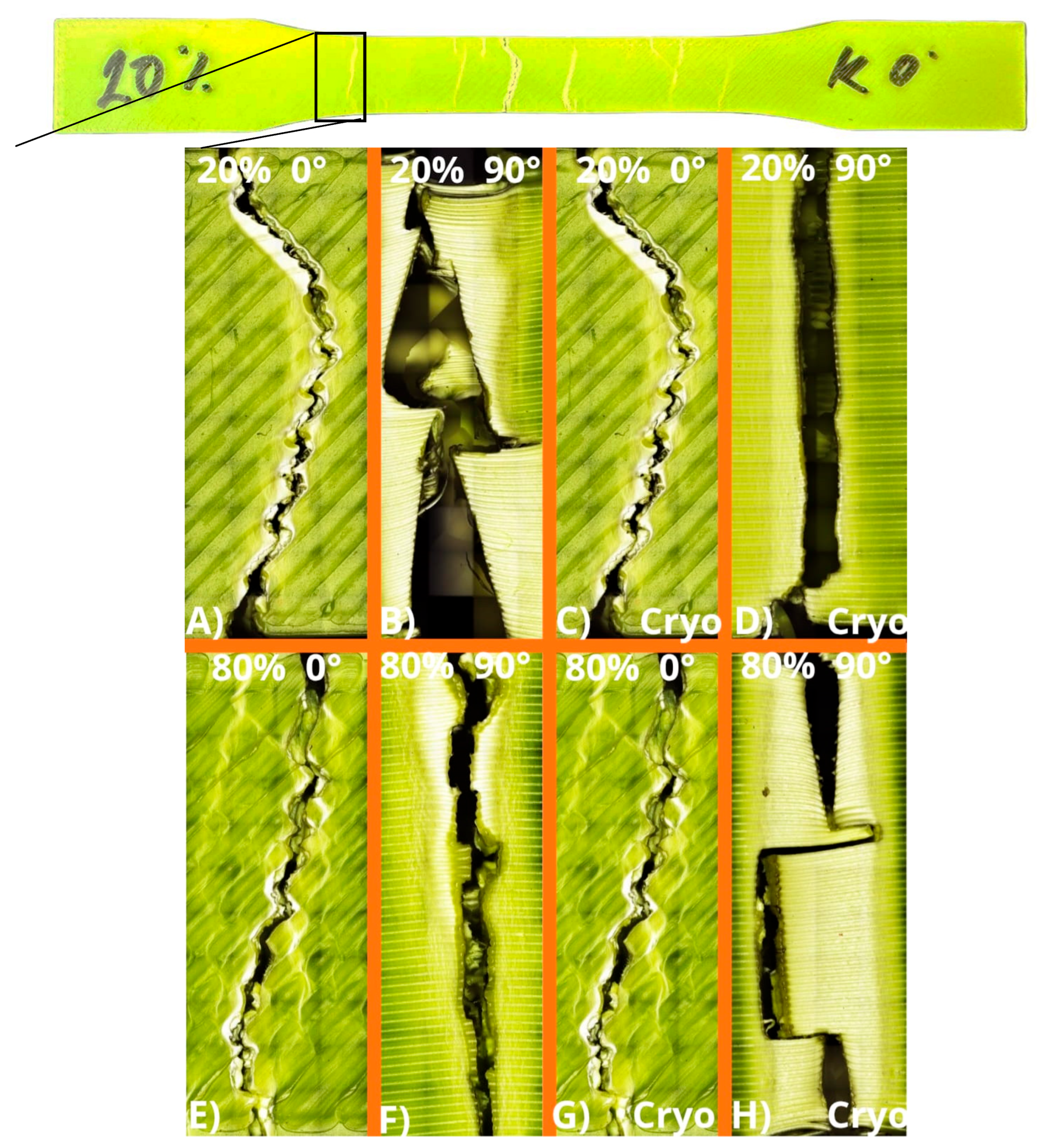
To better understand the mechanical behavior of the printed specimens, microscopic analysis of the fracture surfaces was performed using a confocal microscope Olympus LEXT OLS 5100 (Olympus, Tokyo, Japan). In the experiment, specimens were printed with various layer orientations (0°, 30°, 60°, and 90°) and different infill densities (20%, 40%, 60%, and 80%). For the detailed fracture surface analysis, however, only the extreme parameter values were selected—namely the lowest (20%) and highest (80%) infill densities and the printing angles of 0° and 90°. The selected specimens, in both as-printed and cryogenically pre-treated conditions, were examined after tensile testing to identify differences in layer adhesion, the presence of defects, and the characteristic types of failure.
Representative macroscopic images of the fracture surfaces are shown in Figure 16. The top row (A–D) corresponds to samples with 20% infill, while the bottom row (E–H) shows samples with 80% infill. Within each row, the specimens printed at 0° and 90° angles are compared, both in as-printed (A, B, E, F) and cryogenically pre-treated (C, D, G, H) conditions.
For the 20% infill samples (A and B), the fracture surfaces exhibit distinct interlayer separation and weak filament adhesion, particularly at 90° orientation (B), where delamination along the layer interfaces dominates. The cryogenically treated counterparts (C and D) show a more pronounced brittle character with sharp, clean fracture lines and minimal plastic deformation, especially at 0° orientation (C). It is evident that the cryogenic exposure reduced the polymer chain mobility, limited energy absorption, and weakened the bonding between adjacent layers.
The 80% infill samples (E–H) exhibit significantly more cohesive structures with improved bonding between filaments compared to the 20% series. The 80%/0° sample (E) in the as-printed condition shows ductile tearing along the filament boundaries, while the 80%/90° sample (F) demonstrates a mixed ductile–brittle fracture mode. After cryogenic pre-treatment (G and H), the fracture surfaces became smoother and more reflective, indicating a transition toward brittle fracture, particularly in H, where the 90° orientation resulted in a clean, perpendicular break with minimal layer deformation.
A direct comparison between the as-printed and cryogenically pre-treated specimens clearly demonstrates that the cryogenic process caused:
  • a reduction in plasticity and energy absorption capacity,
  • the formation of sharper and more linear fracture paths,
  • decreased interlayer adhesion, and
  • a shift from ductile to predominantly brittle failure behavior.
While the as-printed samples exhibited gradual crack propagation through multiple layers and evident plastic deformation (especially at higher infill densities), the cryogenically treated samples fractured abruptly, without significant prior yielding. This contrast is most evident when comparing pairs (A–C) and (E–G), where cryogenic exposure transformed ductile failure into brittle fracture, while pairs (B–D) and (F–H) highlight the influence of layer orientation on crack propagation direction.
These observations confirm that higher infill density enhances layer cohesion and resistance to crack propagation, whereas cryogenic exposure decreases ductility and promotes brittle behavior across all tested configurations. The findings are consistent with the mechanical testing results, indicating that the optimal balance between strength and structural integrity is achieved at higher infill densities and intermediate printing angles (30–60°).

4. Discussion

The experimental results showed that the printing angle and the bulk density of the infill significantly affect the mechanical properties of 3D-printed PLA parts. The highest values of tensile strength (36.04 MPa) and yield strength (40.15 MPa) were recorded at a printing angle of 60° and 80% infill, which represents more than 80% improvement over the values achieved at 0° and 20% infill. Similarly, the tensile modulus reached a maximum of 1540.45 MPa (60°/80%) compared to a minimum of 792.24 MPa (0°/20%). This trend confirms that higher infill density significantly improves the strength and stiffness of the parts, while an inappropriate combination of parameters leads to increased porosity and weaker interlayer bonding. Similar results were reported by Iyer et al., who showed that the combination of optimal filler structure and density leads to a significant improvement in mechanical properties [18].
A different relationship was observed in bending tests. The highest values of the flexural modulus (2739.24 MPa) were achieved at 0° and 20% filler, while the maximum flexural strength (58.89 MPa) was achieved at 90° and higher filler densities. This result indicates a different mechanism of stress transfer under tensile and bending stresses. Similar findings were published by Algarni et al., who confirmed, based on numerical and experimental analyses, that the orientation of fibers and filler fundamentally affects the strength of parts [19].
From a microstructural point of view, lower densities (20% and 40%) showed greater porosity and local areas of weakened adhesion between layers, which caused a significant decrease in mechanical properties. Conversely, at 80% infill, a more homogeneous structure and better bonding between fibers were observed, which minimized the risk of delamination. Khosravani et al. pointed out a similar effect, whereby too low a density leads to weakening of the material by gaps, while too high a density can lead to internal stresses and delamination [20]. The type and orientation of the infill also have a significant impact on mechanical properties. Karad et al. emphasize that the correct choice of printing parameters is essential to achieve a balance between strength, weight and production efficiency [21]. Our results confirm that the combination of a 30–60° printing angle with higher infill density (60–80%) represents the optimal setting for applications requiring high strength and stiffness.
Compared to the literature, where Arslan et al. reported that the integration of carbon fibers into PLA significantly improves the tensile strength and elastic modulus [22], our results show that even the optimization of the geometric parameters of the infill itself can lead to significant improvements without the need for material modifications. Similarly, Gupta et al. demonstrated that increasing the infill density leads to better mechanical properties of carbon fiber-reinforced PLA composites [23], which is in agreement with our findings.
Based on the presented results, it can be concluded that the density and orientation of the infill play a crucial role in determining the mechanical response of 3D-printed PLA parts. Higher densities lead to better fracture toughness, while the optimal layering angle ensures a more uniform stress distribution. These results are consistent with the work of Cui et al., Khan et al. and Kadhum, who showed that the right combination of printing parameters allows for a more homogeneous microstructure and higher material toughness [24,25,26].
The novelty of this study lies in the combined evaluation of printing angle and infill density under cryogenic pre-treatment, which has not been comprehensively addressed in previous research. The presented findings provide new insight into how environmental conditioning at sub-zero temperatures influences the anisotropic mechanical response of FFF-printed PLA. This knowledge contributes to optimizing the design of polymer parts used in low-temperature or cyclic loading environments.

5. Conclusions

This study confirmed that print angle and infill density are among the critical parameters affecting the mechanical properties of PLA parts produced by FFF technology. Tensile and flexural test results showed significant differences between the individual configurations, while the effect of cryogenic treatment was also evident.
  • Tensile tests of the as-printed specimens demonstrated a clear dependence of mechanical performance on the filling density and printing orientation. The mechanical properties systematically increased with higher infill density, confirming the positive correlation between material compactness and load-bearing capacity. The lowest tensile strength was observed for the 0°/20% configuration (19.58 MPa), whereas the highest values were achieved at 60°/80% (tensile strength 39.27 MPa, yield strength 40.15 MPa, and elastic modulus 1540.45 MPa). This represents an improvement of approximately 100% in tensile strength and about 54% in both yield strength and modulus compared to the weakest configuration. A subsequent decline at 90° indicates that excessive fiber misalignment can reduce the overall mechanical integrity of printed parts.
  • Flexural testing of the as-printed series confirmed a similar pattern. The lowest flexural strength was obtained for the 0°/20% configuration (50.01 MPa), while the highest value was recorded at 90°/80% (58.89 MPa), representing an increase of approximately 18%. The flexural modulus ranged from 2374 MPa to 2739 MPa, showing only about a 15% difference between the minimum and maximum, which suggests that the stiffness of the material is less sensitive to print orientation than its strength.
  • Cryogenic pre-treatment was found to have a detrimental effect on the tensile properties of PLA specimens. After the treatment, the ultimate tensile strength decreased from 39.27 MPa to 36.04 MPa (−8%), the yield strength dropped by 10%, and the elastic modulus decreased by approximately 14%. These findings indicate that cryogenic exposure induced microstructural changes, reducing the material’s ability to withstand mechanical loads.
  • Flexural performance after cryogenic treatment followed the same degradation trend. The maximum flexural strength (90°/80%) reached 51.39 MPa, which is 12.7% lower than in the as-printed condition, while the flexural modulus dropped to the 2276–2580 MPa range, approximately 6% lower than in untreated samples. This confirms that cryogenic processing adversely affects both strength and stiffness of printed PLA, with a more pronounced impact on tensile than flexural behavior.
In addition to the mechanical testing, fracture surface analysis provided further insight into the failure mechanisms of PLA parts. Microscopic observations revealed that specimens with higher infill densities (80%) exhibited better interlayer cohesion and fewer defects, leading to more uniform and ductile fracture patterns. In contrast, samples with low infill density (20%) showed significant interlayer separation and delamination, especially at 90° orientation, where cracks propagated along the print layers. The cryogenically pre-treated specimens displayed smoother and sharper fracture surfaces with limited plastic deformation, confirming the transition from ductile to brittle behavior caused by low-temperature exposure. These morphological features are consistent with the reduction in strength and modulus observed in the mechanical tests.
The presented results highlight the critical role of printing angle and infill density in determining the mechanical performance of PLA parts produced by FFF. The study demonstrates that optimal combinations of 60°/80% for tensile and 90°/80% for bending provide superior strength and stiffness, while cryogenic pre-treatment reduces mechanical performance due to increased brittleness. The findings contribute to a better understanding of anisotropy and structural optimization in 3D-printed polymers.
These insights are directly applicable in engineering practice, particularly in the design of lightweight load-bearing structures and components operating under variable temperature conditions. Potential applications include biomedical devices, consumer products, and functional prototypes requiring both low weight and sufficient mechanical integrity.
Future work will focus on extending this research to reinforced PLA composites and on developing predictive models to further enhance the mechanical performance and reliability of additively manufactured parts.

Author Contributions

Conceptualization, J.J.F. and L.K.; methodology, M.K. (Michal Krbata) and M.K. (Marcel Kohutiar); software, P.M.; validation, A.B., Z.S. and J.V.; formal analysis, Z.S. and J.V.; investigation, J.J.F., L.K. and P.M.; resources, A.B.; data curation, A.B. and P.M.; writing—original draft preparation, J.J.F. and L.K.; writing—review and editing, M.K. (Michal Krbata) and M.K. (Marcel Kohutiar); visualization, M.K. (Marcel Kohutiar); supervision, Z.S. and J.V.; project administration, J.J.F. and L.K.; funding acquisition, M.K. (Michal Krbata). All authors have read and agreed to the published version of the manuscript.

Funding

This research received no external funding.

Data Availability Statement

The original contributions presented in this study are included in the article. Further inquiries can be directed to the corresponding author.

Conflicts of Interest

The authors declare no conflicts of interest.

References

  1. Fekiač, J.J.; Kakošová, L.; Krbata, M.; Kohutiar, M.; Eckert, M.; Studeny, Z.; Dubec, A. Influence of Infill Geometry and Density on the Mechanical Properties of 3D-Printed Polylactic Acid Structure. J. Manuf. Mater. Process. 2025, 9, 134. [Google Scholar] [CrossRef]
  2. Mahović Poljaček, S.; Donevski, D.; Tomašegović, T.; Vrabič Brodnjak, U.; Leskovšek, M. Mechanical Properties of 3D-Printed PLA Structures Observed in Framework of Different Rotational Symmetry Orders in Infill Patterns. Symmetry 2025, 17, 466. [Google Scholar] [CrossRef]
  3. Birosz, M.T.; Ledenyák, D.; Andó, M. Effect of FDM Infill Patterns on Mechanical Properties. Polym. Test. 2022, 113, 107654. [Google Scholar] [CrossRef]
  4. Almonti, D.; Salvi, D.; Ucciardello, N. Optimization of Printing Parameters for Polyethylene Terephthalate Glycol Thin Honeycomb Structures with Shape-Memory Behaviors. Int. J. Adv. Manuf. Technol. 2025, 136, 4455–4469. [Google Scholar] [CrossRef]
  5. Agrawal, A.P.; Kumar, V.; Kumar, J.; Paramasivam, P.; Dhanasekaran, S.; Prasad, L. An Investigation of Combined Effect of Infill Pattern, Density, and Layer Thickness on Mechanical Properties of 3D Printed ABS by Fused Filament Fabrication. Heliyon 2023, 9, e16531. [Google Scholar] [CrossRef]
  6. Khaliq, J.; Gurrapu, D.R.; Elfakhri, F. Effects of Infill Line Multiplier and Patterns on Mechanical Properties of Lightweight and Resilient Hollow Section Products Manufactured Using Fused Filament Fabrication. Polymers 2023, 15, 2585. [Google Scholar] [CrossRef] [PubMed]
  7. Turaka, S.; Jagannati, V.; Pappula, B.; Makgato, S. Impact of Infill Density on Morphology and Mechanical Properties of 3D Printed ABS/CF-ABS Composites Using Design of Experiments. Heliyon 2024, 10, e29920. [Google Scholar] [CrossRef] [PubMed]
  8. dos Reis, M.Q.; Carbas, R.J.C.; Marques, E.A.S.; da Silva, L.F.M. Effect of the Infill Density on 3D-Printed Geometrically Graded Impact Attenuators. Polymers 2024, 16, 3193. [Google Scholar] [CrossRef]
  9. Naveed, N. Investigating the Material Properties and Microstructural Changes of Fused Filament Fabricated PLA and Tough-PLA Parts. Polymers 2021, 13, 1487. [Google Scholar] [CrossRef] [PubMed]
  10. Guessasma, S.; Belhabib, S. Effect of the Printing Angle on the Microstructure and Tensile Performance of Iron-Reinforced Polylactic Acid Composite Manufactured Using Fused Filament Fabrication. J. Manuf. Mater. Process. 2024, 8, 65. [Google Scholar] [CrossRef]
  11. Fekiač, J.J.; Krbata, M.; Kohutiar, M.; Janík, R.; Kakošová, L.; Breznická, A.; Eckert, M.; Mikuš, P. Comprehensive Review: Optimization of Epoxy Composites, Mechanical Properties, & Technological Trends. Polymers 2025, 17, 271. [Google Scholar] [CrossRef]
  12. Dziewit, P.; Rajkowski, K.; Płatek, P. Effects of Building Orientation and Raster Angle on the Mechanical Properties of Selected Materials Used in FFF Techniques. Materials 2024, 17, 6076. [Google Scholar] [CrossRef]
  13. Hsueh, M.-H.; Lai, C.-J.; Chung, C.-F.; Wang, S.-H.; Huang, W.-C.; Pan, C.-Y.; Zeng, Y.-S.; Hsieh, C.-H. Effect of Printing Parameters on the Tensile Properties of 3D-Printed Polylactic Acid (PLA) Based on Fused Deposition Modeling. Polymers 2021, 13, 2387. [Google Scholar] [CrossRef]
  14. Chicos, L.-A.; Pop, M.A.; Zaharia, S.-M.; Lancea, C.; Buican, G.R.; Pascariu, I.S.; Stamate, V.-M. Infill Density Influence on Mechanical and Thermal Properties of Short Carbon Fiber-Reinforced Polyamide Composites Manufactured by FFF Process. Materials 2022, 15, 3706. [Google Scholar] [CrossRef]
  15. Qayyum, H.; Hussain, G.; Sulaiman, M.; Hassan, M.; Ali, A.; Muhammad, R.; Wei, H.; Shehbaz, T.; Aamir, M.; Altaf, K. Effect of Raster Angle and Infill Pattern on the In-Plane and Edgewise Flexural Properties of Fused Filament Fabricated Acrylonitrile–Butadiene–Styrene. Appl. Sci. 2022, 12, 12690. [Google Scholar] [CrossRef]
  16. Kohutiar, M.; Kakošová, L.; Krbata, M.; Janík, R.; Fekiač, J.J.; Breznická, A.; Eckert, M.; Mikuš, P.; Timárová, Ľ. Comprehensive Review: Technological Approaches, Properties, and Applications of Pure and Reinforced Polyamide 6 (PA6) and Polyamide 12 (PA12) Composite Materials. Polymers 2025, 17, 442. [Google Scholar] [CrossRef]
  17. Orellana-Barrasa, J.; Ferrández-Montero, A.; Ferrari, B.; Pastor, J.Y. Natural Ageing of PLA Filaments, Can It Be Frozen? Polymers 2022, 14, 3361. [Google Scholar] [CrossRef] [PubMed]
  18. Iyer, S.S.G.; Keles, O. Effect of Raster Angle on Mechanical Properties of 3D Printed Short Carbon Fiber Reinforced Acrylonitrile Butadiene Styrene. Compos. Commun. 2022, 32, 101163. [Google Scholar] [CrossRef]
  19. Algarni, M. The Influence of Raster Angle and Moisture Content on the Mechanical Properties of PLA Parts Produced by Fused Deposition Modeling. Polymers 2021, 13, 237. [Google Scholar] [CrossRef]
  20. Khosravani, M.R.; Berto, F.; Ayatollahi, M.R.; Reinicke, T. Characterization of 3D-Printed PLA Parts with Different Raster Orientations and Printing Speeds. Sci. Rep. 2022, 12, 1016. [Google Scholar] [CrossRef] [PubMed]
  21. Karad, A.S.; Sonawwanay, P.D.; Naik, M.; Thakur, D.G. Experimental Study of Effect of Infill Density on Tensile and Flexural Strength of 3D Printed Parts. J. Eng. Appl. Sci. 2023, 70, 104. [Google Scholar] [CrossRef]
  22. Arslan, Y. Effects of ultra-cold temperature on thermoplastic (ASA, PLA) parts produced by 3D FDM printing technology. Sādhanā 2025, 50, 250. [Google Scholar] [CrossRef]
  23. Gupta, A.; Kumar, N.; Sachdeva, A.; Verma, R.; Sharma, G.K.; Kumar, M. Effect of Cryogenic Treatment on the Mechanical Properties of 3D-Printed Polylactic Acid Part. Cryogenics 2024, 145, 104000. [Google Scholar] [CrossRef]
  24. Cui, Y.; Yan, J.; Li, J.; Chen, D.; Wang, Z.; Yin, W.; Wu, Z. Cryogenic Mechanical Properties and Stability of Polymer Films for Liquid Oxygen Hoses. Polymers 2023, 15, 3423. [Google Scholar] [CrossRef] [PubMed]
  25. Khan, I.; Tariq, M.; Abas, M.; Shakeel, M.; Hira, F.; Rashid, A.A.; Koç, M. Parametric Investigation and Optimisation of Mechanical Properties of Thick Tri-Material Based Composite of PLA-PETG-ABS 3D-Printed Using Fused Filament Fabrication. Compos. Part C Open Access 2023, 12, 100392. [Google Scholar] [CrossRef]
  26. Kadhum, A.H.; Al-Zubaidi, S.; Abdulkareem, S.S. Effect of the Infill Patterns on the Mechanical and Surface Characteristics of 3D Printing of PLA, PLA+ and PETG Materials. ChemEngineering 2023, 7, 46. [Google Scholar] [CrossRef]
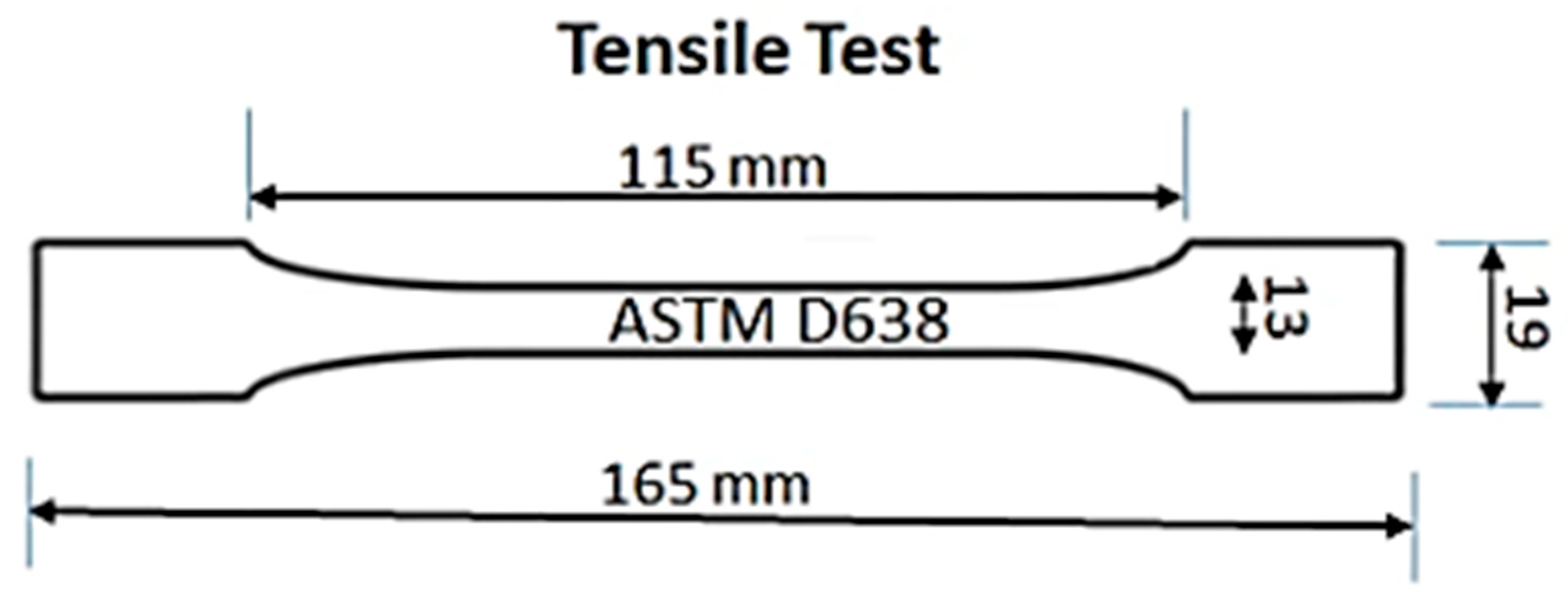
Figure 1. Geometry of tensile test sample according to ASTM D638.
Jmmp 09 00365 g001
Figure 2. Geometry of flexural test sample according to ASTM D790.
Jmmp 09 00365 g002
Figure 3. Configuration of tensile test samples according to ASTM D638 at different printing angles (0°, 30°, 60°, 90°).
Jmmp 09 00365 g003
Figure 4. Configuration of flexural test samples according to ASTM D790 at different printing angles (0°, 30°, 60°, 90°).
Jmmp 09 00365 g004
Figure 5. Internal structure of samples at different printing angles (0°, 30°, 60°, 90°) and infill densities (20%, 40%, 60%, 80%).
Jmmp 09 00365 g005
Figure 6. Yield strength of PLA samples (as-printed) at different printing angles and infill densities.
Jmmp 09 00365 g006
Figure 7. Tensile strength of PLA samples (as-printed samples) at different printing angles and infill densities.
Jmmp 09 00365 g007
Figure 8. Elastic modulus of PLA samples (as-printed samples) at different printing angles and infill densities.
Jmmp 09 00365 g008
Figure 9. Yield strength of PLA samples (cryogenic pre-treated samples) at different printing angles and infill densities.
Jmmp 09 00365 g009
Figure 10. Tensile strength of PLA samples (cryogenic pre-treated samples) at different printing angles and infill densities.
Jmmp 09 00365 g010
Figure 11. Tensile elastic modulus of PLA samples (cryogenic pre-treated samples) at different printing angles and infill densities.
Jmmp 09 00365 g011
Figure 12. Flexural modulus test results (as-printed samples) at different printing angles and infill densities.
Jmmp 09 00365 g012
Figure 13. Flexural strength test results (as-printed samples) at different printing angles and infill densities.
Jmmp 09 00365 g013
Figure 14. Flexural modulus test results (cryogenic pre-treated samples) at different printing angles and infill densities.
Jmmp 09 00365 g014
Figure 15. Flexural strength test results (cryogenic pre-treated samples) at different printing angles and infill densities.
Jmmp 09 00365 g015
Figure 16. Fracture surfaces of PLA specimens after tensile testing, manufactured using the MJF technology with different infill densities and printing orientations. Samples marked as “Cryo” were subjected to cryogenic treatment: (A) 20% infill—0° orientation, (B) 20% infill—90° orientation, (C) 20% infill—0° orientation (after cryogenic treatment), (D) 20% infill—90° orientation (after cryogenic treatment), (E) 80% infill—0° orientation, (F) 80% infill—90° orientation, (G) 80% infill—0° orientation (after cryogenic treatment), (H) 80% infill—90° orientation (after cryogenic treatment).
Jmmp 09 00365 g016
Table 1. Overview of Materials, Equipment, and Printing Parameters.
CategoryParameterValue/Description
MaterialMaterial nameBambu Lab PLA Basic
Material typeIndustrial-grade PLA
Chemical compositionPoly(lactic acid) (C3H4O2)n with trace additives for color and thermal stability
Filament diameter1.75 mm
Density1.24 g/cm3
Glass transition temperature (Tg)60 °C
Melting temperature160 °C
Heat deflection temperature52 °C (at 0.45 MPa)
Tensile strength (manufacturer data)35 MPa (X-Y), 31 MPa (Z)
Young’s modulus (manufacturer data)2580 MPa (X-Y), 2060 MPa (Z)
Elongation at break (manufacturer data)12.2 ± 1.8% (X-Y), 7.5 ± 1.3% (Z)
Bending Strength76 ± 5 MPa (X-Y), 59 ± 6 MPa (Z)
Impact strength26.6 ± 2.8 kJ/m2; 7.9 ± 1.2 kJ/m2 (notched) (X-Y), 13.8 ± 0.9 kJ/m2 (Z)
3D PrinterPrinter modelBambu Lab P1S
Slicing softwareBambu Studio version 2.2.2.56 (default PLA profile)
Sample configurationsPerimeter contour count2
Number of samples per configuration5
Estimated wall thickness range0.2 mm
Sample geometryASTM D638 Type I (tensile testing standard)
ASTM D790 (bending testing standard)
Build parametersNozzle temperature240 °C
Bed temperature55 °C
Nozzle diameter0.4 mm
Layer height0.2 mm
Infill structureCubic
Infill density20%, 40%, 60%, 80%
Layer orientationHorizontal
Disclaimer/Publisher’s Note: The statements, opinions and data contained in all publications are solely those of the individual author(s) and contributor(s) and not of MDPI and/or the editor(s). MDPI and/or the editor(s) disclaim responsibility for any injury to people or property resulting from any ideas, methods, instructions or products referred to in the content.