Article

Green Innovation Practices: A Case Study in a Foundry

1
Department of Engineering, University of Perugia, Via Duranti 93, 06125 Perugia, Italy
2
F.A. Engineering S.r.l., Via Protomartiri Francescani, 111, 06081 Assisi, Italy
3
Meehanite Technology Ltd., Kuokkamaantie 4, 33800 Tampere, Finland
*
Authors to whom correspondence should be addressed.
J. Manuf. Mater. Process. 2024, 8(3), 111; https://doi.org/10.3390/jmmp8030111
Submission received: 18 April 2024 / Revised: 17 May 2024 / Accepted: 24 May 2024 / Published: 26 May 2024

Abstract

:
The foundry industry is responsible for the production of several potentially polluting and hazardous compounds. One of the major sources of pollution is the use of organic binders for the manufacturing of sand cores and sand moulds. To address this problem, in recent years, the use of low-emission products, known as inorganic binders, has been proposed. Their use in ferrous foundries, otherwise, is limited due to some problematic features that complicate their introduction in the manufacturing process, as often happens when a breakthrough innovation is introduced. In light of this, the aim of this work is to provide a Green Innovation Practice (GIP) to manage the introduction of green breakthrough innovations, as previously described, within an existing productive context. This practice was applied to better manage the experimental phase of the Green Casting Life Project, which aims to evaluate the possibility of using inorganic binders for the production of ferrous castings. After describing the state of the art of GIPs and their application in manufacturing contexts, the paper described the proposed GIP and its application to a real case consisting of testing inorganic binders in a ferrous foundry.

1. Introduction

The foundry industry is fundamental for the economy and society. In Europe alone, for instance, in 2021, the foundries produced 14 million metric tonnes of metal, valued at EUR 41 billion and employing 260 thousand people [1]. However, the foundry industry is responsible for the production of several potentially polluting and hazardous compounds [2]. One of the major sources of pollution is the use of organic binders for the manufacturing of sand cores and sand moulds. As shown in [3], the use of organic binders, like furan binders, is responsible for the production of PAHs and BTEX due to the thermal decomposition that the binders face when the fluid metal is poured. To address this problem, in recent years, the use of low-emission products, known as inorganic binders, has been proposed [4,5,6]. The most studied and used are realised by mixing sodium silicate or aluminium silicate with water, so the resulting emissions of hazardous and polluting compounds are strongly reduced [7]. Despite their great potential, nowadays, inorganic binders are used on an industrial scale exclusively in the manufacturing of non-ferrous castings, mainly in aluminium [8]. Instead, their application in ferrous foundries on an industrial scale is so problematic that there is no trace in the literature. The bibliographic research carried out on Scopus using the research key words “Inorganic Binder Ferrous”, “Inorganic Binder Iron,” and “Inorganic Binder Steel”, in fact, did not highlight the presence of any paper or article that testifies the application of inorganic binders in ferrous foundries. In the literature [9], there are only references relating to experiments and presumed applications in industrial plants without providing any specification of production. As shown in [10], this gap can be due to two main factors. The first is the different reputation that generally characterises green innovation in comparison with “classic” innovation. This difference, in fact, is due to the absence of an immediate return (economic and productive), which instead occurs when an innovation specifically designed to increase productivity or quality is introduced. The second is the relevant level of complexity that this kind of innovation intrinsically presents, mainly because of the introduction of breakthrough technologies that generally require great changes in the manufacturing process. The aim of this work is to provide a Green Innovation Practice (GIP) to manage the introduction of breakthrough innovations within an existing productive context. This practice was applied to better manage the experimental phase of the Green Casting Life Project, which aims to evaluate the possibility of using inorganic binders for the production of ferrous castings. This innovation is very important because it could eliminate one of the main sources of emissions in ferrous foundries. Managing the introduction of breakthrough innovation is such a complex task that the use of a GIP is required as described in this paper. The meaning of GIP and the GIP developed and used are presented in Section 2. Section 3 describes the application of the GIP in the design and execution of a testing activity in a ferrous foundry. Section 4 gives the results of this study, followed by a discussion of these results in Section 5.

2. Green Innovation Practices

The current study describes an innovation practice, consisting in a procedure that can help improve the performance of a green innovation process. In particular, in this paper, the application of this methodology to an experiment carried out inside the Green Casting Life Project is described.

2.1. Definition and State of the Art

Concerning the meaning of green innovation, several works have proposed different definitions, all of which share the intent of reducing the impact of production activities on the environment. For instance, green innovation is defined as “a novelty used in technologies that incorporate energy saving, pollution prevention, waste recycling, green product designs, and corporate environmental management” [11], or “green innovation (GI) is the transformation of the operations and processes in such a way that it benefits the natural environment” [12].
According to these definitions, it is clear that a great number of activities can be considered GIs. Therefore, a classification is needed. According to [13], GIs can be distinguished as green products, green marketing, green processes, and green management that are designed for decreasing the consumption of energy, increasing the efficient use of resources, controlling polluting emissions, improving waste recycling, and improving the performance of the organisation. Ref. [14] investigates this topic in depth, providing a wider classification of the different activities that can be considered GIs based on the field that they affect (energy, water, supply chain, etc.) and analysing how they are applied by the top 500 global companies. Furthermore, the study shows another important topic: how companies globally are working to reduce their impact on the environment through the implementation of GIs. But why have manufacturing industries decided to adopt this policy? Ref. [13] lists a number of reasons for this: to comply with the new eco-friendly rules, to have a positive branding image, to improve the firms’ performance, and to have a competitive advantage. In fact, the manufacturing industry is one of the major waste producers that throws off the environmental balance, so customers, society, and government organisations are putting more and more pressure on this industry to conserve energy and resources, preserve the environment, and focus on a single industry as concerns about global pollution grow [13]. On the other hand, research shows that companies face problems in adopting Green Innovation Practices [15]. The reasons for this difficulty are varied and can be attributed to different factors, such as consumer resistance to green product innovation [16]. However, for most firms, the main problem is that Green Innovation Practices are still in the primary stage of exploration, and they do not have relevant theoretical research as a guide [14].

2.2. Proposed GIP

In light of this, it is clear that organising and managing the introduction of a GI in a manufacturing firm is far from easy. This is related to the fact that, often, a GI represents a breakthrough, which is a radical, disruptive, or discontinuous innovation [17]. This means that implementing such activities requires a great deal of effort for the firms, mainly because of the complexity that they introduce into the manufacturing system in terms of technology and management. In this context, a practice that provides guidance on how to approach this problem would be a valuable resource. Regrettably, the literature’s research yielded no reliable findings. Therefore, the purpose of the work presented is to describe a new GIP that aims to manage and facilitate the introduction of a breakthrough green innovation. Furthermore, in the next chapter, the application of this GIP to manage the introduction of a green innovation in a ferrous foundry will be described.
Despite the existence of other improvement techniques, the creation of this procedure was necessary because of the nature of the process analysed: as stated before, a green innovation is often a breakthrough. The use of traditional management techniques such as the DMAIC [18] or the Deming cycle (also known as PDCA) [19] would have been unsuitable. In fact, these methodologies are conceived to guarantee a continuous improvement of the process where they are applied, achieving good results without requiring significant changes to the manufacturing process.
The GIP presented can be deconstructed into the following steps:
  • Stakeholder management;
  • Process mapping;
  • Sub-processes analysis;
  • Design and planning of the modified manufacturing process;
  • Implementation and control.
Even if this GIP for managing green breakthroughs can be considered innovative, it is based on using pre-existing management instruments or techniques well known and documented in the literature, such as the IDEF0 methodology and stakeholder management techniques (Power/Grid Matrix, Salience model).

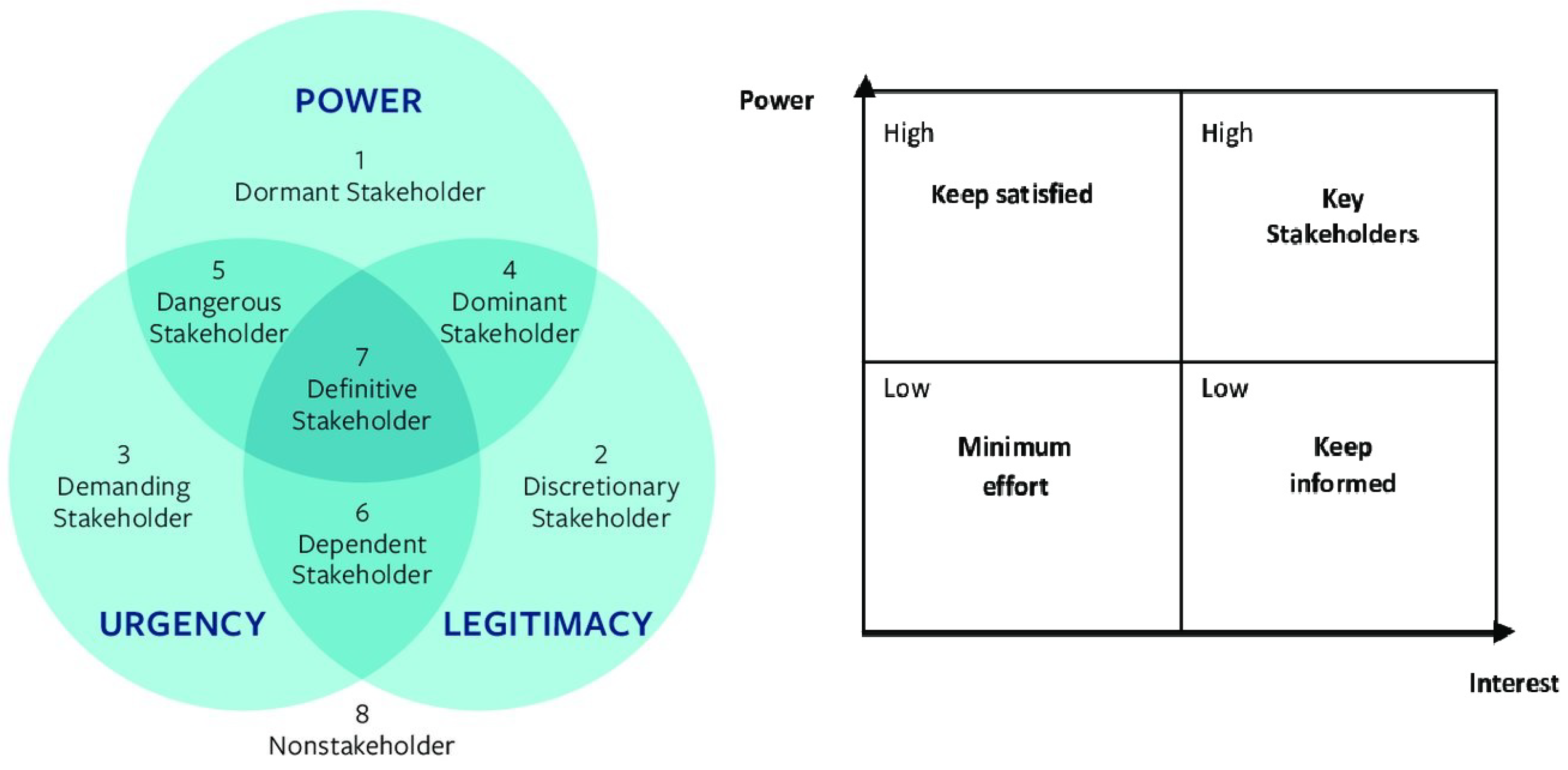
2.2.1. Stakeholder Management

To predict all the consequences for a large number of players, a correct stakeholder management procedure is necessary. In fact, as suggested in [20], the results obtained from a study that analysed 400 strategic decisions showed that half of the decisions failed (which means they were not implemented, were partially executed, or had unsatisfactory results) in large part because decision makers failed to consider key stakeholders’ interests and information. As indicated in [21], the first step of this process consists in identifying the stakeholders involved, which means taking into account all the potential parties interested in the project. To achieve this, it is crucial to conduct an analysis of the manufacturing process that the GI will modify. This task is often not as simple as it appears [22]: at the beginning of the work, the implications in the background are far from clear, and sometimes only time can help to fully understand the scenario. The result of this task is a complete list of all the stakeholders, which is the basis for carrying out the next phase, the stakeholder classification. According to [21], this phase is important to understand the sensations, beliefs, and expectations of the stakeholders in order to correctly engage them, which is fundamental to achieving a successful outcome. First of all, it is important to analyse the position and role of each stakeholder, evaluating factors such as power, impact, influence, and interest. On the basis of this, it is possible to prioritise the involvement of each stakeholder [23] using the management instruments available in the literature, such as the Power/grid matrix [24] or the Salience model [25] (Figure 1).

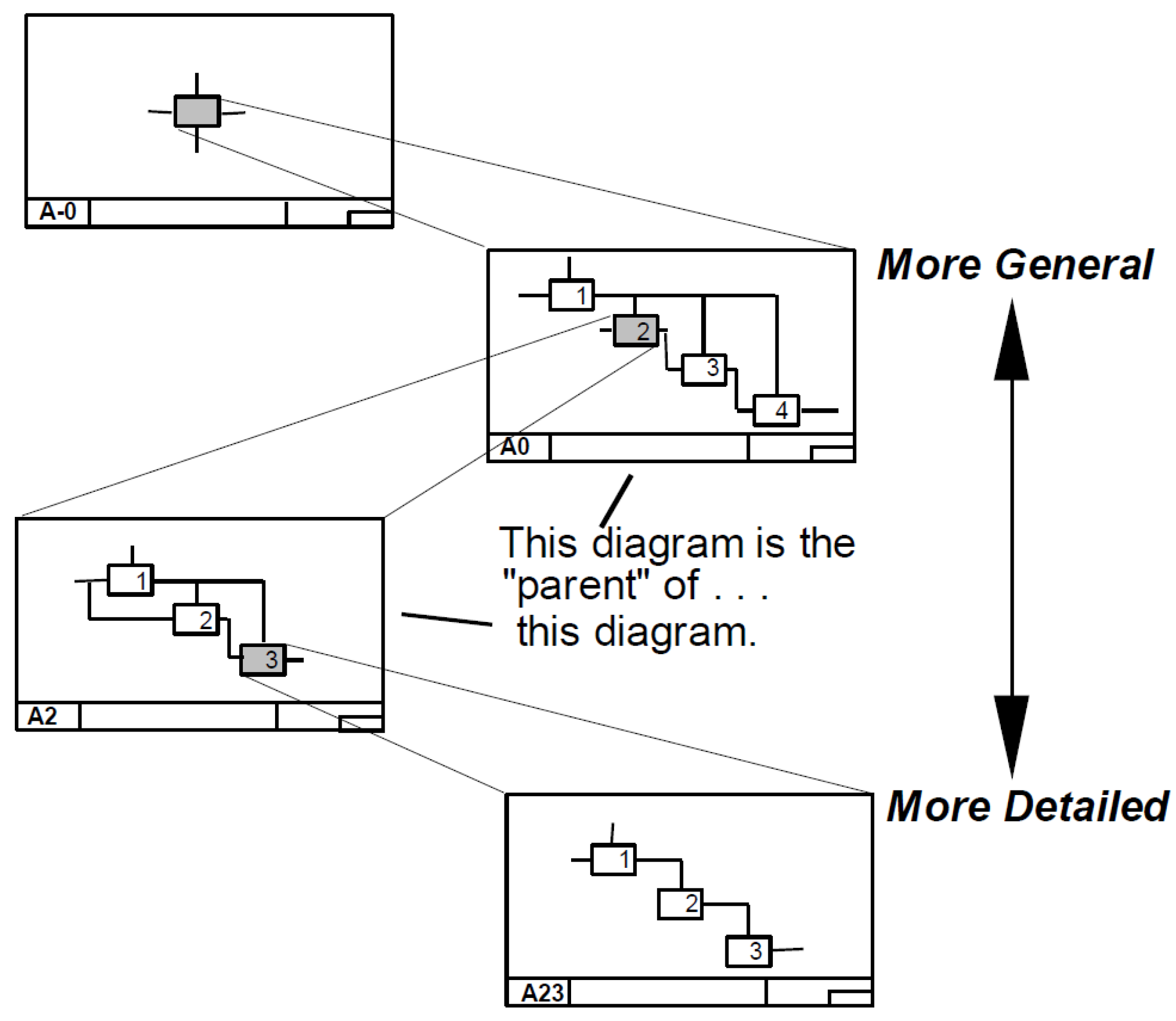
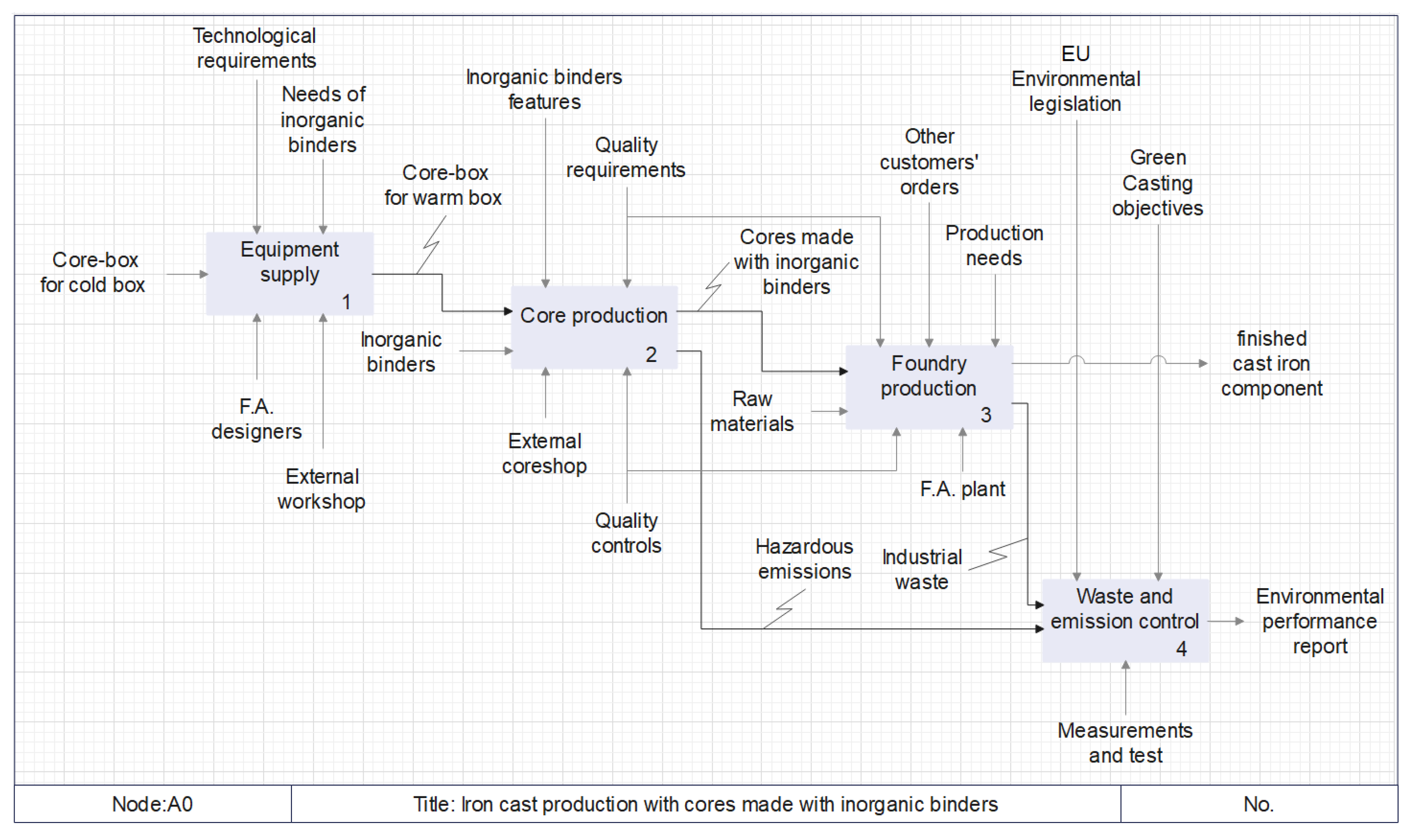
2.2.2. Process Mapping

In this phase, the study and optimisation of process flow are facilitated by diagrams [28]. To improve a production process, it is important to thoroughly understand its operation. A flowchart is a simple tool for visualising and communicating the sequence of operations in a process [29] (Figure 2). Through the use of these instruments, the innovation process is analysed and deconstructed into “main tasks”, making it possible to visualise the process in an organised and schematic way. Flowcharts are classified into various forms with unique boxes and notational principles. The two most typical boxes used in a flowchart are a rectangular box that represents a processing step (or activity) and a choice, which is frequently represented as a diamond. To delve deeper into this topic, a flowchart for mapping the production process of house structure components is described in [30].

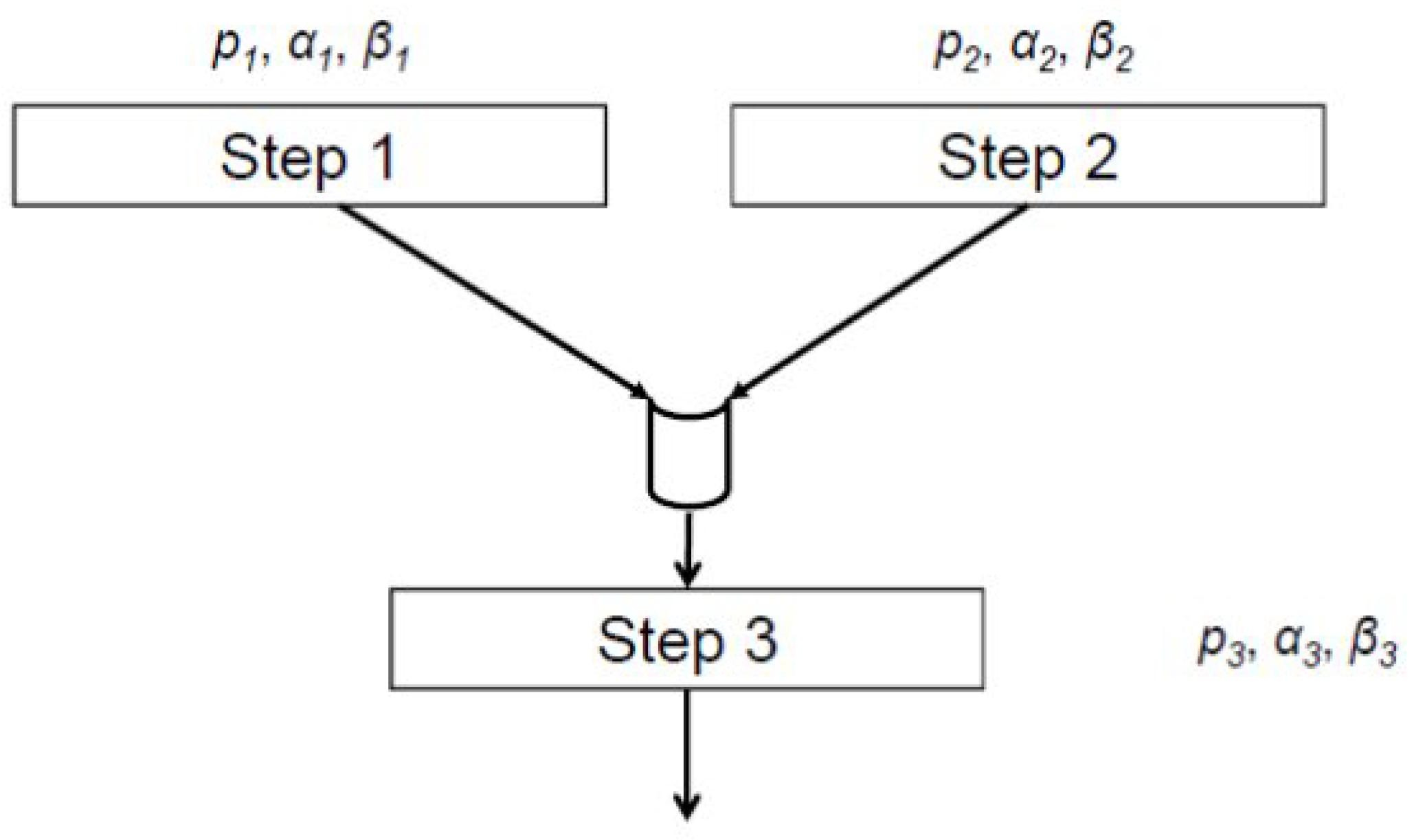
2.2.3. Sub-Processes Analysis

Once the main tasks have been identified and declared, it is necessary to analyse all the sub-tasks that compose each step of the process. This is a very important phase that can directly influence the result; even a small detail, if overlooked, can compromise the outcome, so it is clear that a correct analysis has to be carried out to avoid risks. For this purpose, instruments such as IDEF, which is a family of modelling languages, can be very helpful in creating an explanatory graph of the process that allows the visualisation of all the sub-tasks and their inputs, outputs, controls and mechanisms. IDEF0 is a functional enterprise modelling tool that was developed in the late 1970s through the US Air Force’s Integrated Computer Aided Manufacturing (ICAM) program. IDEF stands for ICAM Definition. IDEF0 is used to represent the functional (i.e., activity- or process-oriented) framework of a system [32]. The IDEF0 is a process modelling technique and industrial standard as well, with extended literature references in the analysis and design of projects in the fields of manufacturing, aerospace, business, and information systems science and technology [33]. The work presented in [34] provides a complete description of how the IDEF0 model works. The IDEFO models are made up of a hierarchy of connected diagrams. Each diagram is built around a diagonal row of boxes (often three to six boxes per diagram) that are linked together by arrows.
The boxes reflect activities that are described by the active verb phrase contained within them. Arrows depict the relationship between activities in terms of the information or items used, produced, or required by those activities. Arrows entering the left side of a box are inputs (I) to the activity, arrows entering the top of a box are controls (C), and arrows exiting the right side of a box are outputs (O) from the activity. Finally, a mechanism (M) is a person, system, or device associated with carrying out the action, represented by an arrow entering the base of a box. This arrow structure is known as the ICOM structure (Figure 3).
Each diagram is identified by a ’node number’ that indicates its position in a model’s hierarchy (Figure 4). A node index and node tree are useful for displaying the relationships between all of the diagrams in a model, while a data dictionary can be used to summarise all the sources and destinations of objects, information, or data. An IDEF0 model is made up of a series of connected activity diagrams presented in node number order that depict the issue under consideration. The ’viewpoint’ (node A-I) and ’context’ (node A0) diagrams at the top of the hierarchy explain the author’s perspective on the subject as well as the model’s scope. The analyst’s desired level of information determines the depth of the model hierarchy (the number of diagrams below the viewpoint). The reasons for selecting IDEF0 are different: it is one of the few functional modelling methodologies that are popular with the industrial community; it is superior to many other functional modelling methodologies in terms of simple graphics, conciseness, rigour and precision, consistent methodology, levels of abstraction, and separation of organisation from function; and it is in fact a de facto international standard [35].

2.2.4. Design and Planning of the Modified Manufacturing Process

After the analysis of the process and its full understanding, it is possible to think about how to correctly introduce the innovation into the pre-existing manufacturing process. Obviously, this step does not yield a unique solution, so the production manager must choose the one that best suits the firm’s needs. Once the correct solutions have been chosen, it must be decided how to apply them, including planning the timing and deciding the resources to invest. To carry out this phase, the use of design techniques such as robust design methodologies is recommended. Ref. [36] contains a review of some of the most commonly used practices.

2.2.5. Implementation and Control

This phase applies the decisions made in the previous phases and controls the results to ensure that they align with what is expected. Otherwise, it is necessary to think and apply corrective actions. To achieve this, a wide range of methodologies and practices can be used, both for monitoring [37] and inspection [38]. It is important to note that, except in the case of unpredictable events, the number of these interventions should be low because of the work performed in the previous phases.

3. Case Study

This section explains how the proposed GIP was applied to the Green Casting Life project. The project aims to demonstrate the feasibility of introducing inorganic binders in ferrous casting production. Nowadays, the use of this technology for manufacturing sand cores and moulds is limited because of some problematic features, such as low humidity resistance. In addition to this, their use in ferrous foundries is nowadays strongly limited because of the high melting temperature that ferrous metals present (around 1400 °C), which reduces the collapsibility of cores and moulds. This problem is not evident in the production of non-ferrous alloys, such as aluminium alloys, because of the lower temperature (around 700 °C). Indeed, the use of these binders in aluminium casting production has already been introduced in the Best Available Techniques Reference Document for the Smitheries and Foundries Industry [8]. Given this, it is evident that implementing this technology in ferrous foundries can enhance their environmental performance. To achieve this, the project incorporates an experimental phase that tests various binders from various European producers to assess their effectiveness. The execution and results obtained from a previous test are described in [10]. This test, like the other one reported in this work, consisted in producing cast iron castings (around 100 pieces) using the green sand method and cores made with inorganic binders. The productive process can be divided into two main parts: core manufacturing and casting manufacturing. The foundry that hosts the experiment is able to carry out both processes in its own plant for its routine production, but for this test, it was necessary to commission the manufacturing of the cores to an external core maker because of the different machinery needed. In fact, the production of cores with inorganic binders requires a different process, and the core shooters used in the foundry for the production of cores with organic binders are not suitable for this purpose. The main difference between the production of core with organic and inorganic binders is how curing is obtained. In the first case, the “cold box” process is generally used, where a chemical compound reacts with the binder to harden the sand-binder mixture. Otherwise, inorganic binders necessitate a “warm box” process, requiring high temperatures (around 150 °C) to cure the cores. This means that a core shooter designed for producing cores with organic binders is not suitable for inorganic core production because it lacks the equipment needed for providing heat. In addition to this, the core box, which is the pattern used to shape the cores, also needs to be adapted or made from scratch. Due to these needs that were underestimated, the first test, known as Test A, faced some issues. To prevent them from being repeated, the proposed GIP was applied to the test described in this paper, which will be referred to as Test B.

3.1. Stakeholder Management

Although this phase was already underway prior to the execution of Test A, the results obtained led to its further development. The second analysis of the stakeholders involved in the Green Casting Life project showed some interesting points. The first concerns the category of inorganic binder producers: this category, in fact, contains both companies that produce organic and inorganic binders and companies that produce only inorganic binders. This means that for the first group, the inorganic binders are only a small part of their production, whereas for the second group, the inorganic binders are a core business. Clearly, this suggests that companies manufacturing inorganic binders may be more motivated to achieve a positive outcome from the tests, whereas companies producing both binding systems may be less motivated, as a failure would not impact their business.
The second point is how foundry customers can contribute to the transition to inorganic binders. Consider, for example, a foundry that produces mechanical parts for automotive companies. It is well known that in the last few years, public opinion has increased its interest in environmental issues, especially concerning the emissions coming from the use of vehicles. This led automotive companies to gain awareness about their role in the issue, and, year after year, they have begun to apply several solutions to reduce the environmental impact of their products and productions. In light of this, automotive companies could consider their involvement in an environmental protection-centred project as something positive because it could surely help them appear more sensible to environmental themes and increase their popularity among the public. In addition to this, their direct involvement in the project would surely represent an interesting opportunity for the project itself, giving it a boost to success. Consequently, the foundries that supply the automotive companies, under their pressure, would be more motivated to obtain positive results because this would put them in a favourable position in the market.
Furthermore, it was necessary to create a new category that could include both the core makers and the tool suppliers that, in the previous analysis, were not included in the list of stakeholders.

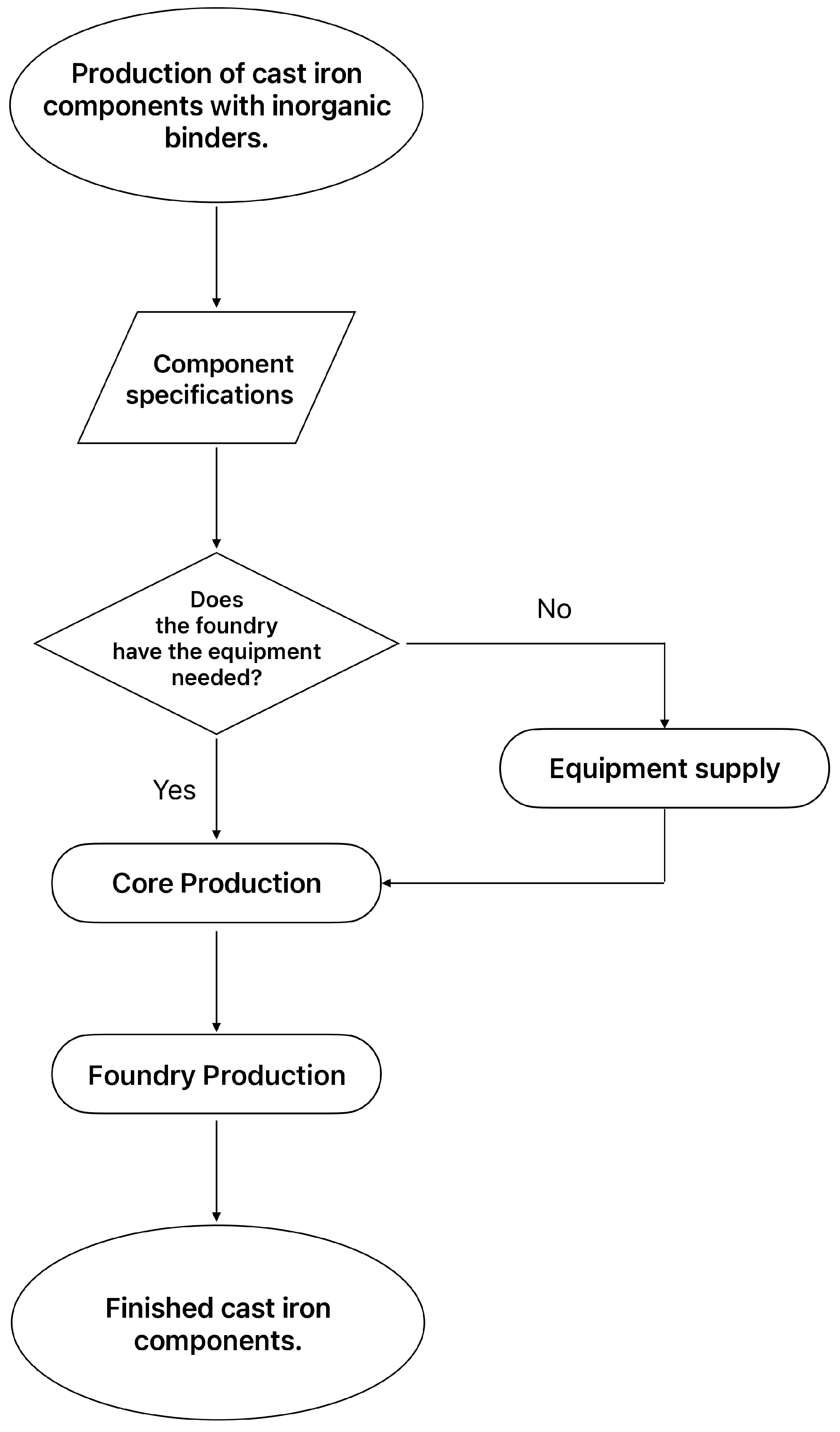
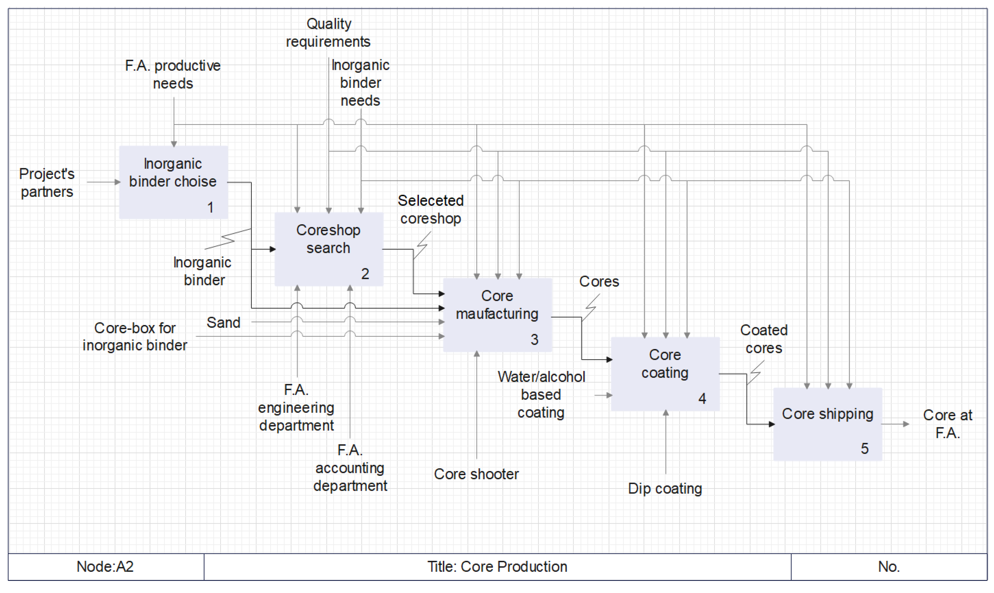
3.2. Process Mapping

The main activities present in the manufacturing process that was carried out for Test B are common to all green sand casting production. In Figure 5, a flowchart is reported, containing the essential steps that provide a high-level representation of the process.

3.3. Sub-Process Analysis

The analysis of the subprocesses and the results obtained from Test A revealed several problems, especially concerning the following:
  • Using an adapted aluminium core box previously used in production with organic binders;
  • Shipping of the cores from the core shop to the foundry;
  • Coating of the cores;
  • Identification of the castings.
These problems were identified thanks to the experience gained with the previous Test A but also thanks to the creation of a map of the sub-processes using IDEF0 that helped visualise all the mechanisms and elements that take part in each of them. The next pictures depict the map of the whole production process (A0, Figure 6) and the sub-process of core manufacturing (A2, Figure 7).

3.4. Design and Planning of the Modified Manufacturing Process

In this phase, some changes were proposed in order to solve the problems related to the introduction of inorganic binders in the manufacturing process:
  • A steel core box was designed and produced specifically for the production in Test B. In fact, in Test A, the use of an aluminium core box resulted in significant dimensional errors in the cores due to the thermic deformation of the pattern’s material.
  • Instead of using electric resistances to heat the core box, a thermal fluid heating system was created. This allowed for better heat distribution on the pattern surface, which guaranteed better curing.
  • The shipping was carried out using better packaging (in order to protect the cores from impacts), and, to prevent humidity, the shipping pallet was sealed, and some bags with silica gel were added inside.
  • To guarantee the correct identification of the finished castings, a mark was printed on the inner surface of the sand moulds using specific stamps with a letter for every type of binder used. Compared to Test A, where the letters were incised on the cores, this change produced a clear code on the metal surface.
  • In Test B, it was decided to produce castings of smaller size to better control the processes.
The changes formulated were discussed with the firm, which began the planning phase. The operations were organised internally, following the procedures usually adopted by the foundry. In this phase, except for the changes described above, it was not necessary to introduce any significant modifications in the manufacturing process.

3.5. Implementation and Control

The usual procedures used in the plant were confirmed as happened in the first test. However, in this second test, the control phase showed better results. This can be related to the higher effort put into planning the previous phases. For instance, in this case, the casting identification was carried out without any problems thanks to the presence of clearly visible letters. In addition to this, thanks to the improvement process implemented in the previous phases, the number of cores that broke during shipping and coating was negligible.

4. Results

Compared to Test A, applying the proposed GIP to Test B allowed for better results and improved process management. For instance, a significant improvement is that it was possible to clearly distinguish the castings produced with the different binders. By observing and measuring the surface finish of the different pieces, it was possible to evaluate the performance of the inorganic binders tested, which showed a surprising improvement in comparison to Test A.
Table 1 summarises the differences between Test A and Test B. The first row displays some practices used in Test A that the analysis identified as problematic. The second row describes the problems caused by each of these techniques, while the third row lists the technical changes adopted in Test B to address these issues.
All these modifications allowed for obtaining castings of good quality that the foundry and the customer judged as adequate. This experience showed that the introduction of innovative inorganic binders in ferrous foundries can provide good results. In this case, this goal was achieved thanks to an accurate analysis and planning conducted using the proposed GIP.

5. Conclusions

The present work describes a Green Innovation Practice (GIP) for managing the introduction of breakthrough innovation into an existing production framework. As previously illustrated, the presented GIP consists of different steps that help to analyse the operative context and the existing manufacturing process and plan how to introduce green innovations through the use of known and well-documented methodologies, such as IDEF0. The Green Casting Life project, which aims to verify the feasibility of using inorganic binders in ferrous foundries, served as a real case to test (Test B) the effectiveness of the GIP. The results of Test B showed a significant increase in quality compared to the outcomes of a previous similar test (Test A). This increase could be attributed to the suggested ability of GIP to identify prospective issues or errors that may develop as a result of disregarding or overlooking certain process aspects. This could be a significant achievement that gives firms a valuable tool for managing the complexity of implementing green innovations in manufacturing processes. In the authors’ opinion, to definitively demonstrate the effectiveness of the GIP, further tests in different contexts should be carried out. Furthermore, the GIP could be improved by adding an additional step that identifies the unexpected events that the process may face through the use of risk management techniques.

Author Contributions

Conceptualization, G.F. and I.S.; investigation, G.F.; writing original draft, G.F.; writing review and editing, G.F. and S.S.; supervision I.S.; project administration S.S. and S.T.; funding acquisition, S.T. All authors have read and agreed to the published version of the manuscript.

Funding

The searches mentioned in this paper are funded by the European Union LIFE Program, Green Casting LIFE Project (LIFE21-ENV-FI-101074439). Views and opinions expressed are, however, those of the author(s) only and do not necessarily reflect those of the European Union or CINEA. Neither the European Union nor the granting authority can be held responsible for them. Jmmp 08 00111 i001

Data Availability Statement

The original contributions presented in the study are included in the article; further inquiries can be directed to the corresponding authors.

Conflicts of Interest

Ivan Stefani is employed by F.A. Engineering s.r.l., Sara Tapola is employed by Meehanite Technology ltd, and Stefano Saetta and Gianluca fratta are employed by University of Perugia. The funders had no role in the design of the study; in the collection, analyses, or interpretation of data; in the writing of the manuscript; or in the decision to publish the results.

References

  1. EUROFER. European Steel in Figures 2023; EUROFER—The European Steel Association: Brussels, Belgium, 2023. [Google Scholar]
  2. Krishnaraj, R. Control of pollution emitted by foundries. Environ. Chem. Lett. 2015, 13, 149–156. [Google Scholar] [CrossRef]
  3. Holtzer, M.; Bobrowski, A.; Dańko, R.; Kmita, A.; Żymankowska-Kumon, S.; Kubecki, M.; Górny, M. Emission of polycyclic aromatic hydrocarbons (PAHs) and benzene, toluene, ethylbenzene and xylene (BTEX) from the furan moulding sands with addition of the reclaim. Metalurgija 2014, 53, 451–454. [Google Scholar]
  4. Rabbii, A. Sodium silicate glass as an inorganic binder in foundry industry. Iran. Polym. J. 2001, 10, 229–235. [Google Scholar]
  5. Zhang, Y.S.; Xia, L.; Huang, J. Study on A New Inorganic Binder for Fabricating Casting Mold and Core. Appl. Eng. Mater. 2011, 287, 1603–1606. [Google Scholar] [CrossRef]
  6. Dańko, R.; Kmita, A.; Holtzer, M.; Dańko, J.; Lehmhus, D.; Tapola, S. Development of inorganic binder systems to minimise emissions in ferrous foundries. Sustain. Mater. Technol. 2023, 37, e00666. [Google Scholar] [CrossRef]
  7. Merta, V.; Beňo, J.; Obzina, T.; Radkovský, F.; Kroupová, I.; Lichý, P.; Folta, M.; Janovská, K.; Nguyenová, I.; Dostál, M. Innovative Inorganic Binder Systems for the Production of Cores for Non-Ferrous Metal Alloys Reflecting the Product Quality Requirements. Metals 2021, 11, 733. [Google Scholar] [CrossRef]
  8. Best Available Techniques (BAT). Reference Document for the Smitheries and Foundries Industry; Technical Report; European Commission: Brussels, Belgium, 2024. [Google Scholar]
  9. Vykoukal, M.; Burian, A.; Přerovská, M. GEOPOL®. The Innovated Environment Friendly Inorganic Binder System. Arch. Foundry Eng. 2019, 19, 109–116. [Google Scholar] [CrossRef]
  10. Saetta, S.; Stefani, I.; Tapola, S. Complexity of green innovation in manufacturing: A case in a foundry. Procedia Comput. Sci. 2024, 232, 11–20. [Google Scholar] [CrossRef]
  11. Xue, M.; Boadu, F.; Xie, Y. The Penetration of Green Innovation on Firm Performance: Effects of Absorptive Capacity and Managerial Environmental Concern. Sustainability 2019, 11, 2455. [Google Scholar] [CrossRef]
  12. Xu, N.; Fan, X.; Hu, R. Adoption of green industrial internet of things to improve organizational performance: The role of institutional isomorphism and green innovation practices. Front. Psychol. 2022, 13, 917533. [Google Scholar] [CrossRef]
  13. Wang, H.; Khan, M.A.S.; Anwar, F.; Shahzad, F.; Adu, D.; Murad, M. Green innovation practices and its impacts on environmental and organizational performance. Front. Psychol. 2021, 11, 553625. [Google Scholar] [CrossRef] [PubMed]
  14. Zhang, L.; Zhao, S.; Cui, L.; Wu, L. Exploring green innovation practices: Content analysis of the fortune global 500 companies. Sage Open 2020, 10, 2158244020914640. [Google Scholar] [CrossRef]
  15. Musaad O, A.S.; Zhuo, Z.; Musaad O, A.O.; Ali Siyal, Z.; Hashmi, H.; Shah, S.A.A. A Fuzzy Multi-Criteria Analysis of Barriers and Policy Strategies for Small and Medium Enterprises to Adopt Green Innovation. Symmetry 2020, 12, 116. [Google Scholar] [CrossRef]
  16. Khan, M.A.S.; Du, J.; Malik, H.A.; Anuar, M.M.; Pradana, M.; Yaacob, M.R.B. Green innovation practices and consumer resistance to green innovation products: Moderating role of environmental knowledge and pro-environmental behavior. J. Innov. Knowl. 2022, 7, 100280. [Google Scholar] [CrossRef]
  17. Datta, A.A.; Srivastava, S. (Re)conceptualizing technological breakthrough innovation: A systematic review of the literature and proposed framework. Technol. Forecast. Soc. Chang. 2023, 194, 122740. [Google Scholar] [CrossRef]
  18. Rifqi, H.; Zamma, A.; Ben Souda, S.; Hansali, M. Lean Manufacturing Implementation through DMAIC Approach: A Case Study in the Automotive Industry. Qual. Innov. Prosper. 2021, 25, 54–77. [Google Scholar] [CrossRef]
  19. Snee, R.D.W. Edwards Deming’s “Making AnotherWorld”. Am. Stat. 2008, 62, 251–255. [Google Scholar] [CrossRef]
  20. Bryson, J.M. What to do when Stakeholders matter. Public Manag. Rev. 2004, 6, 21–53. [Google Scholar] [CrossRef]
  21. Project Management Institute, Inc. The Standard for Project Management. In A Guide to the Project Management Body of Knowledge (PMBOK® Guide; Project Management Institute, Inc.: Newtown Square, PA, USA, 2021. [Google Scholar]
  22. De Vries, H.; Verheul, H.; Willemse, H. Stakeholder identification in IT standardization processes. In Proceedings of the Workshop on Standard Making: A Critical Research Frontier for Information Systems, Seattle, WA, USA, 12–14 December 2003; pp. 12–14. [Google Scholar]
  23. Mitchell, R.K.; Agle, B.R.; Wood, D.J. Toward a theory of stakeholder identification and salience: Defining the principle of who and what really counts. Acad. Manag. Rev. 1997, 22, 853–886. [Google Scholar] [CrossRef]
  24. Scholes, K.; Johnson, G.; Whittington, R. Exploring Corporate Strategy; Financial Times Prentice Hall: Hoboken, NJ, USA, 2002. [Google Scholar]
  25. Raha, A.; Hajdini, I.; Windsperger, J. A multilateral stakeholder salience approach: An extension of the stakeholder identification and salience framework. Ind. Mark. Manag. 2021, 97, 1–9. [Google Scholar] [CrossRef]
  26. Kujala, J.; Lehtimäki, H.; Freeman, E.R. A stakeholder approach to value creation and leadership. In Leading Change in a Complex World: Transdisciplinary Perspectives; Tampere University Press: Helsinki, Finland, 2019. [Google Scholar]
  27. Júnior, P.; Geciane, P.; Pacífico, O.; Júnior, S. Project Stakeholder Management: A Case Study of a Brazilian Science Park. J. Technol. Manag. Innov. 2015, 10, 39–49. [Google Scholar] [CrossRef]
  28. Kemper, B.; de Mast, J.; Mandjes, M. Modeling process flow using diagrams. Qual. Reliab. Eng. Int. 2010, 26, 341–349. [Google Scholar] [CrossRef]
  29. Shakil, M.; Ullah, M.R.; Lutfi, M. Process flow chart and factor analysis in production of a jute mills. J. Ind. Intell. Inf. 2013, 1, 247–254. [Google Scholar] [CrossRef]
  30. Yu, H.; Al-Hussein, M.; Nasseri, R. Process flowcharting and simulation of house structure components production process. In Proceedings of the 2007 Winter Simulation Conference (IEEE), Washington, DC, USA, 9–12 December 2007; pp. 2066–2072. [Google Scholar]
  31. Franceschini, F.; Galetto, M.; Genta, G.; Maisano, D.A. Selection of quality-inspection procedures for short-run productions. Int. J. Adv. Manuf. Technol. 2018, 99, 2537–2547. [Google Scholar] [CrossRef]
  32. Presley, A.; Liles, D.H. The use of IDEF0 for the design and specification of methodologies. In Proceedings of the 4th Industrial Engineering Research Conference, Nashville, TN, USA, 24–25 May 1995; pp. 442–448. [Google Scholar]
  33. Spanidis, P.M.; Pavloudakis, F.; Roumpos, C. Introducing the IDEF0 Methodology in the Strategic Planning of Projects for Reclamation and Repurposing of Surface Mines. Mater. Proc. 2021, 5, 26. [Google Scholar] [CrossRef]
  34. Colquhoun, G.J.; Baines, R.W.; Crossley, R. A state of the art review of IDEFO. Int. J. Comput. Integr. Manuf. 1993, 6, 252–264. [Google Scholar] [CrossRef]
  35. Cheng-Leong, A.; Li Pheng, K.; Keng Leng, G.R. IDEF*: A comprehensive modelling methodology for the development of manufacturing enterprise systems. Int. J. Prod. Res. 1999, 37, 3839–3858. [Google Scholar] [CrossRef]
  36. Hasenkamp, T.; Arvidsson, M.; Gremyr, I. A review of practices for robust design methodology. J. Eng. Des. 2009, 20, 645–657. [Google Scholar] [CrossRef]
  37. Stavropoulos, P.; Chantzis, D.; Doukas, C.; Papacharalampopoulos, A.; Chryssolouris, G. Monitoring and control of manufacturing processes: A review. Procedia CIRP 2013, 8, 421–425. [Google Scholar] [CrossRef]
  38. Genta, G.; Galetto, M.; Franceschini, F. Inspection procedures in manufacturing processes: Recent studies and research perspectives. Int. J. Prod. Res. 2020, 58, 4767–4788. [Google Scholar] [CrossRef]
Figure 1. Two of the most used instruments for stakeholder classification: the Salience model [26] (left) and the Power/Interest matrix [27] (right).
Jmmp 08 00111 g001
Figure 2. Example of flowchart [31].
Jmmp 08 00111 g002
Figure 3. IDEF0 representation [32].
Jmmp 08 00111 g003
Figure 4. Deconstruction overview [32].
Jmmp 08 00111 g004
Figure 5. Essential steps of the manufacturing process.
Jmmp 08 00111 g005
Figure 6. The A0 map, realised using IDEF0, includes all the main processes needed for the production of finished cast-iron components.
Jmmp 08 00111 g006
Figure 7. The A2 map, realised using IDEF0, includes all the sub-processes needed for the production of cores using inorganic binders.
Jmmp 08 00111 g007
Table 1. Problems emerged during Test A and solutions adopted in Test B.
Test A: Problematic PracticesProblem CausedTest B: Changes Adopted
The core box used in the process was made of aluminium.Due to the thermal expansion of the pattern, the dimensions of the cores mismatched the reference dimensions.The core box was made from scratch using steel.
The core box was heated with electric resistance.The cores were not properly cured due to an irregular distribution of the heat.The core box was provided with a thermal fluid heating system.
The cores were not correctly packaged, and no precautions against moisture were taken.During the transport to the foundry, vibrations and moisture weakened the cores. Lot of them broke.The cores were packaged with foam rubber, and bags filled with silica were arranged in the pallet.
The mark was put on the cores.The code impressed on the metal pieces was hard to spot and often not even visible. The castings were not distinguishable.The mark was put on the moulds; the sign was clear and visible.
Disclaimer/Publisher’s Note: The statements, opinions and data contained in all publications are solely those of the individual author(s) and contributor(s) and not of MDPI and/or the editor(s). MDPI and/or the editor(s) disclaim responsibility for any injury to people or property resulting from any ideas, methods, instructions or products referred to in the content.

