Article

Process Optimization and Distortion Prediction in Directed Energy Deposition

1
School of Engineering, University of Quebec in Abitibi-Témiscamingue, Rouyn-Noranda, QC J9X 5E4, Canada
2
Mechanical Engineering Laboratory, National Engineering School of Monastir, University of Monastir, Monastir 5019, Tunisia
3
Unité Génie de Production Mécanique et Matériaux, National Engineering School of Sfax (ENIS), Sfax 3038, Tunisia
4
Research Institute on Mines, The Environment University of Quebec in Abitibi-Témiscamingue, Rouyn-Noranda, QC J9X 5E4, Canada
*
Author to whom correspondence should be addressed.
J. Manuf. Mater. Process. 2024, 8(3), 116; https://doi.org/10.3390/jmmp8030116
Submission received: 25 April 2024 / Revised: 24 May 2024 / Accepted: 28 May 2024 / Published: 30 May 2024

Abstract

:
Directed energy deposition (DED), a form of additive manufacturing (AM), is gaining traction for its ability to produce complex metal parts with precise geometries. However, defects like distortion, residual stresses, and porosity can compromise part quality, leading to rejection. This research addresses this challenge by emphasizing the importance of monitoring process parameters (overlayer distance, powder feed rate, and laser path/power/spot size) to achieve desired mechanical properties. To improve DED quality and reliability, a numerical approach is presented and compared with an experimental work. The parametric finite element model and predictive methods are used to quantify and control material behavior, focusing on minimizing residual stresses and distortions. Numerical simulations using the Abaqus software 2022 are validated against experimental results to predict distortion and residual stresses. A coupled thermomechanical analysis model is employed to understand the impact of thermal distribution on the mechanical responses of the parts. Finally, new strategies based on laser scan trajectory and power are proposed to reduce residual stresses and distortions, ultimately enhancing the quality and reliability of DED-manufactured parts.

1. Introduction

Additive manufacturing (AM) has revolutionized manufacturing by enabling the creation of complex, customized parts with unmatched design freedom and efficiency. Unlike traditional subtractive methods like machining, AM utilizes a computer-aided design (CAD) model to build parts layer-by-layer. Directed energy deposition (DED), a specific AM technology, uses a focused energy source (often a laser) to melt and deposit raw materials (powder or wire) onto a substrate, building a 3D object. This allows for highly complex geometries and near-net shapes, minimizing material waste. However, achieving precise geometries and desired mechanical properties requires meticulous control of process parameters (e.g., laser power and feed rate) to prevent potential part failures like distortion, residual stress, shrinkage, and porosity, which can significantly impact part quality and lead to rejection.
Optimizing the quality of DED parts hinges on selecting the most suitable combination of process parameters. According to the literature, the most significant factors influencing DED quality are overlayer distance, powder feed rate, laser path, laser power, and beam spot size. While adjusting laser power and path can enhance dimensional accuracy, it can also influence the microstructure of the deposited material, potentially affecting its mechanical properties. Therefore, identifying the ideal DED deposition conditions requires a delicate balancing act: achieving desired dimensional accuracy, maintaining a favorable microstructure, and optimizing other fabrication parameters to minimize defects.
The quality of printed parts is determined by various aspects, including surface roughness, dimensional accuracy, mechanical properties, and adherence to specifications. Porosity [1], shrinkage, and maintaining precise dimensional accuracy [2] remain the primary challenges associated with DED technology [3,4].
Other created defects during the additive process, including gas pores and a lack of fusion pores, provide part fatigue and fracture. In addition, thermal cycling variations are a potential source of distortion and residual stresses that lead to corrosion, cracking, and fatigue. These defects lead to dimensional and geometric discrepancies between the source model and the printed part [5]. Some parts require several hours to be printed, and it is not reasonable to continue printing when an unacceptable surface distortion occurs. For that reason, several academic and professional institutions have contributed to improving the quality and reliability of the AM process [6].
DED technology is now positioned as one of the most advanced manufacturing processes since it allows us to produce metal parts conforming to the most challenging design specifications. A few researchers have conducted experimental trials on DED processes, but they have been limited by costs and the long periods required to set them up. In addition, the obtained results remain insufficient for understanding the physics that occurs during the manufacturing process. For that reason, the ability to predict and precisely control the behavior of materials is a major challenge in AM technology. Quantifying parts’ mechanical and thermal behavior in DED processes is the key to producing high-quality products. To achieve this goal, researchers employ a combination of numerical, experimental, and analytical approaches to predict and prevent the occurrence of major defects. On the one hand, Chen et al. [7] compared Rosenthal’s method with real-time melt images using X-ray photography to predict microstructure and deposition quality in terms of depth and length variations as a function of laser power and travel speed. Ren and Mazumder [8] applied an optical probe that is focused on the build surface. The spectra are collected during the DED process using a Smart Optical Monitoring System (SOMS) with a spectrometer to calculate the porosity rate of each layer. Whiting et al. [9] introduced acoustic emission (AE) measurements as a method of controlling powder flow in a DED process to provide the operator with an accurate measurement of the powder mass flow rate through the machine nozzle so that the actual mass flow rate (in AE) and the desired flow rate can be compared using a mathematical model to describe the actual mass flow rate as a function of the RMS of the AE signal. Svetlizky et al. [10] reviewed the key aspects controlling laser–material interactions during DED, the thermal behavior of the melt, advanced in situ monitoring, interaction mechanisms, and the characterization of defects in the deposited materials. Song et al. [11] proposed a predictive control strategy to monitor the melt temperature in real time. A pyrometer has been used to monitor the melt temperature, and a laser power controller has been used to stabilize it. Numerical simulation analysis using the finite element method (FEM) is a valuable tool for predicting DED distortion and residual stress [12]. For instance, Ninpetch et al. [13] developed a 3D FEM model to predict these factors in a titanium tibial tray fabricated using Laser Powder Bed Fusion (LPBF), a related AM technology. Their findings highlighted the significant influence of heat source power and layer thickness on distortion near the interface between the tray and support structure due to differing stiffness between the solid part and support. This emphasizes the importance of FEM analysis in understanding the impact of process parameters on DED outcomes.
In addition, FE models and experimental tests can be used to study the effect of various process conditions to find the optimal set of operational parameters [14]. Corbin et al. [15] used a DED experimental setup of Ti–6Al–4V to study the effect of substrate thickness and preheating temperature on distortion. Daniel et al. [16] developed predictive models of the actual deposition height of the part manufactured by the DED to improve our understanding of the process and calculate the expected properties of the parts before actual manufacturing. Using developed artificial neural networks (ANNs), geometric deviations can be anticipated by adapting the laser power, scanning speed, and powder feed. But generating these models is often time-consuming.
In this paper, numerical simulations and novel analytical reliability analyses are implemented to detect and predict the distortions of a part obtained by the DED process. The modeling and simulation are performed using the Abaqus software [17] coupled with a modified benchmarks input files representing the geometries, serial events, scan strategies, and physical properties of the material and laser. The developed numerical approach made it possible to conduct coupled thermomechanical simulations, including the proper use of the progressive activation of elements, and several printing strategies such as laser scan modes, preheating, and laser power. The definition of each layer in the thermomechanical simulations requires many discrete steps. At the beginning of each step, the material activation event sequence data are crossed with a finite element mesh activation event sequence. This combination of the trajectory (laser motion or mesh) with amplitude (power) was defined by an advanced event series in exact time and space. In this study, finite element simulations of DED process parameters were conducted to predict part deformations, residual stresses, and microstructure evolutions during layer-by-layer printing. In addition, a coupled parameterized thermomechanical analysis model was developed. The thermal distribution determined the mechanical response and the thermal behavior of the part. Therefore, the developed model has allowed the results of the heat transfer problem to be used as an input in the form of thermal stress in the mechanical simulation. Finally, new strategies have been proposed to homogenize simulation results and experimental observations and, consequently, decrease the residual stress values and mechanical distortion.

2. Constitutive Model

The numerical method employed to simulate the AM process is a transient thermomechanical model incorporating coupled multi-physics phenomena. This model acknowledges the influence of thermal history on the mechanical response of the material while assuming the minimal impact of the mechanical response on the thermal history. Consequently, a decoupled approach is adopted, where the solution from the heat transfer analysis serves as the thermal load input for the subsequent mechanical analysis.
In this study, the effects of scan mode, preheating, and the Zig-Zag strategy on the mechanical and thermal response during printing are investigated. The most suitable strategies will be recommended to decrease the manufactured part’s distortion and residual stress. Scan mode refers to the variation in the laser’s travel pattern and power during powder fusion. Different scan modes, such as unidirectional, bidirectional, alternating, and laser power variation can significantly impact heat distribution and material microstructures. Preheating involves heating the build bed before printing to reduce temperature gradients during fusion, improve layer bonding, and minimize deformations. The Zig-Zag strategy deposits powder in a raster pattern to distribute heat and residual stresses more evenly, enhancing the dimensional stability of the printed part. Thermomechanical finite element DED simulations are conducted to evaluate these strategies and to compare them with printing experiments [18]. The distortion and residual stresses of the printed parts are compared, and the strategy that minimizes these defects is identified. Based on our findings, the most suitable DED printing strategies for fabricating high-quality metal parts are recommended. Guidelines for selecting the optimal strategy based on the geometric features and desired properties of the part are also provided.
The following section details the governing equations employed in the simulations. The constitutive material models used in this work incorporate anisotropy formulations considering both nonlinear isotropic behavior and isotropic ductile damage to capture the material’s response under thermomechanical loads.

2.1. Thermal Model

The heat source model is the most fundamental aspect of computationally analyzing processes, as it is the primary factor in predicting the temperature field for AM. The temperature history of AM components influences the distortion, fatigue behavior of structures, and residual stresses. That is why it is necessary to use an appropriate heat source to predict distortion and residual stress [19]. The model was developed using an equilibrium equation between the surface heat flux caused by the laser effect and loss due to conduction, convection, and radiation [20]. A thermal simulation was conducted using the Lagrangian thermal model. Mesh was used with eight-node linear brick elements (DC3D8). The moving heat source was generated using a user subroutine, DFLUX, in the Abaqus code. The heat transfer equation is expressed as [21]
ρ c T t ( x , y , z , t ) = q ( x , y , z , t ) + Q ( x , y , z , t )
ρ c T t = x k T x + y k T y + z k T z + Q
where c and ρ are the effective specific heat capacity and density of the material. T is the temperature; q is the heat flux; t is the time; and Q is the internal heat generation rate.
The Fourier heat flux constitutive relation is provided as
q = k T
where k is the effective thermal conductivity.
If the temperature difference is high, the heat loss due to thermal radiation between the AM parts and the environment becomes essential. This radiation has been modeled by the standard Stefan–Boltzmann relation. The radiative heat transfer between the side and top surfaces can be described by
Qrad = ε σ(Tamb4T4)
Heat loss is calculated from convection by Newton’s law of cooling as
Qconv = ℎ (TambT)
ℎ is the convective heat transfer coefficient. ε describes the emissivity of the surface, and σ is the Stefan–Boltzmann constant.
Two models of volumetric energy distribution are generally used in AM: (i) the rotatory Gaussian body model and (ii) the Goldak model.

2.1.1. Gaussian Model

The rotatory Gaussian body model is more consistent with reality for high-energy, deep-penetration AM work, such as electron beams or laser welding. The heat density is
Q ( r , y ) = Q 0   ( 3 r 2 r 0 ( y ) 2 )
where r0(y) is the radius of the heat source at z, r is the current radius from the center of the heat source, and Q0 is the energy input.
A mathematical model of the heat source of the rotary Gaussian model with incremental power—density distribution is shown in Figure 1.

2.1.2. Goldak Model

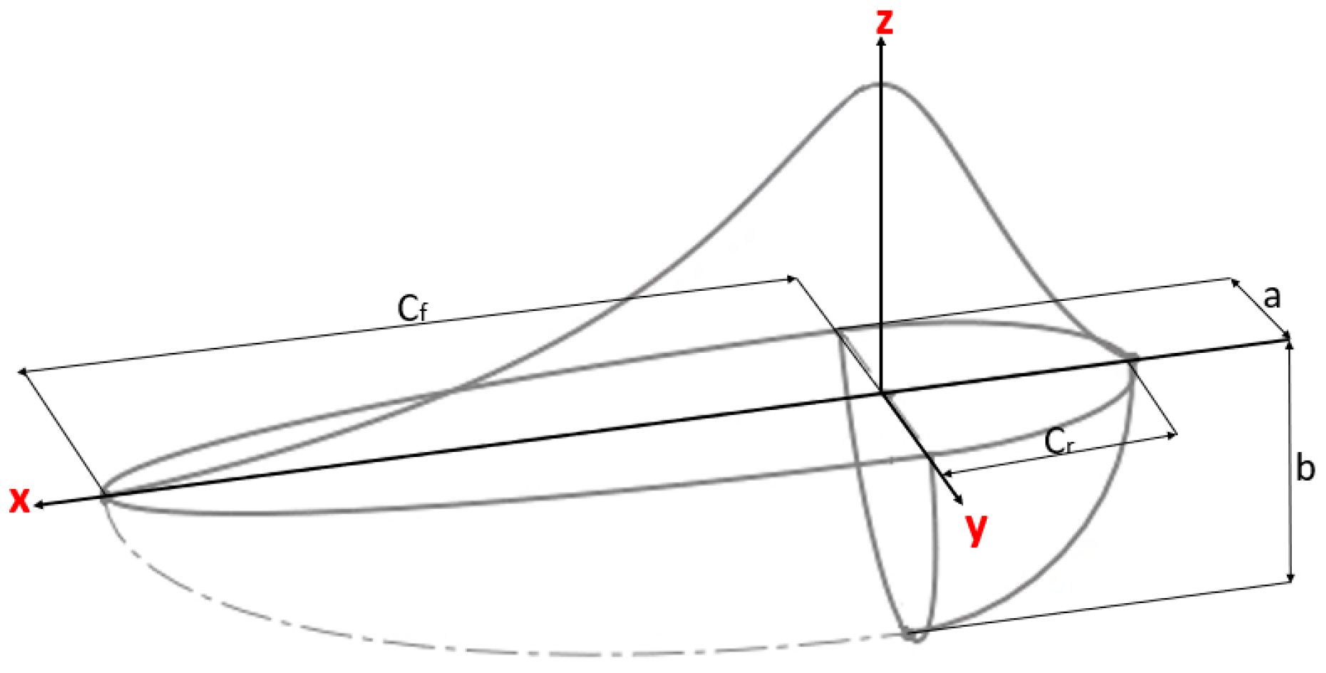
Another volumetric flux model, as proposed by Goldak [22], is a three-dimensional thermal model with a distributed heat source. The distribution of the applied heat is presented in Figure 2. The heat distribution within Goldak’s moving heat source is described by [23]
q = q f = 6 3   f f a f b c Π   Q Π     ( 3 x 2 a f 2 )     ( 3 y 2 b 2 ) ( 3 z 2 c 2 )         i f   x 0
q = q r = 6 3   f r a r b c Π   Q Π     ( 3 x 2 a r 2 )     ( 3 y 2 b 2 ) ( 3 z 2 c 2 )                   i f   x < 0
where η is the printing efficiency. U and I are the printing voltage and current.
Generally, the sum of the heat fraction, f, between the heat deposited in the front, af, and the rear, ar, regions is equal to two [24]. The model parameters are gathered in Table 1.
The heat distribution of the Goldak model is shown in Figure 2.
In the thermal analysis, the part of the energy generated by the laser source that is lost before being absorbed by the material was neglected.

2.2. Structural Analysis

The numbers and times of the steps in the mechanical simulation are defined as the thermal simulation. The nodal temperature is calculated from the heat transfer and is used as the thermal load for the mechanical simulation. A 3D elasto-plastic mechanical model is applied to calculate the residual stress and distortion from the thermal model data. During cooling, plastic hardening stabilizes the material’s strength, leading to residual stresses that are caused by thermal evolutions and gradients. The substrate is often heated before manufacturing. Indeed, if the substrate temperature increases, the gradient between the melting and the substrate is less important, and there are fewer residual stresses in the part [25].
The mechanical analysis consists of using the thermo-elasto-plastic combination with the Von Mises elasticity criterion defined as [26]
σ v = 1 2 [ ( σ 1 σ 2 ) 2 + ( σ 2 σ 3 ) 2 + ( σ 3 σ 1 ) 2 ]
where σ1, σ2, and σ3 are the principal stresses. The general relation of the mechanical stress equilibrium for a body is written as
∆ . σ = 0
where σ is the stress tensor.
The stress is dependent on strain through the stiffness tensor, C, as
σ = C ε
where ε is the strain, and C is the material stiffness tensor.
The calculation of thermal strains is shown in the equation above, where α is the thermal expansion coefficient.
εthermal = α (TTref)
The temperature change in an AM simulation reflects a thermal expansion in the mechanical analysis, which is the external load on the model [27].
Thermal strains caused by temperature gradients induce additional elastic and plastic strains, where the total strain is
∆εtotal = ∆εplastic + ∆εelastic + ∆εV + ∆εthermal
The standard expression for the stress tensor from Hooke’s low equation is written as
σ i j = E 1 + v ε i j t o t δ i j ε i j * + δ i j v 1 2 v ( ε k k t o t ε k k * )
The internal forces in the AM process define residual stresses. Therefore, the strain in AM is driven by permanent causes due to residual stresses and temporarily due to thermal expansion.
This mechanical modeling is based on the fundamental equations of continuous environments that control the deformation and transformation of the material, such as the dynamic equilibrium equation, the behavior law equations, and the conservation of mass equation.
In all cases, the basic principles of mass, momentum, and energy conservation have to be respected:
ρ t + v x ρ x + v y ρ y + v z ρ z = ρ ( V x x + V y y + V z z ) ( v .   ρ ) (   . v   )
D ρ D t = ρ x v . ρ

3. Numerical Finite Element Model

This work presents a transient, sequentially coupled thermomechanical finite element (FE) analysis for the directed energy deposition (DED) of Inconel 625. The Abaqus software is employed to predict the evolution of transient temperature and strain fields during the DED process. To achieve this, a key aspect involves a sequential solution strategy. The heat transfer problem is solved first to obtain the transient temperature history. This temperature field is then incorporated into the subsequent stress analysis through two key considerations: thermal–mechanical coupling, where temperature variations induce non-uniform thermal expansion within the material that is integrated into stress calculations, and temperature-dependent material properties, where thermo-physical and mechanical properties like thermal conductivity and Young’s modulus are dynamically adjusted based on the calculated temperature field, resulting in a more accurate prediction of stress evolution. Notably, numerical simulations inherently require significant computational resources, scaling proportionally with the desired mesh refinement [28]. The thermal analysis for each elementary layer follows a three-step approach: heating, cooling, and a subsequent cooling phase. For the mechanical boundary conditions, all nodes on the substrate surface are fixed in all directions to constrain movement.

3.1. Geometry Description

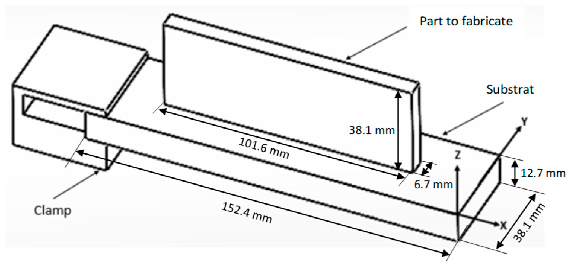
The model of the following part was chosen to simulate it on the Abaqus software, which is presented in Figure 3. This model consists of three parts: a clamp; a substrate; and a part that is 6.7 mm wide, 101.6 mm long, and 38.1 mm high with 42 layers, where each layer is equal to 3.35 mm in width and 0.9071 mm in height. The substrate used was 152.4 mm in length, 38.1 mm in width, and 12.7 mm in thickness. The clamp is a fixture with a height of 28.6 mm, width of 38.1 mm, and length of 38.1 mm to measure distortion during printing.
Three numerical thermocouples, TC1, TC2, and TC3, are displayed within the software, as shown in Figure 4. One laser displacement sensor (LDS) under the substrate with distances of 127 mm, 76.2 mm, 25.4 mm, and 150 mm from the x-axis and 19.05 mm from the y-axis is disposed to measure distortion.
Dunbar et al. [29] showed that two different scanning strategies lead to different heat accumulations, thus inducing different results. The standard method for printing layers used in all strategies is shown in Figure 5. The laser path is implemented using a series of events replicating the laser scanning strategy movement to create 42 layers. During the processing of the nth layer, the laser travels from left to right, following the order shown in Figure 5a. For the subsequent return pass (layer n + 1), the laser follows the same order as the previous pass, but in the reverse direction, starting from right to left (Figure 5b).

3.2. Thermomechanical Simulation

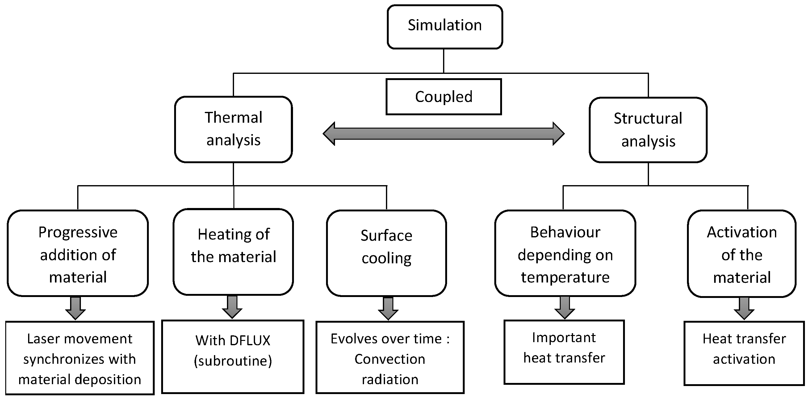
A thermomechanically coupled simulation based on transient heat transfer and a static structure was analyzed. The thermal loads were introduced to the part during printing. Otherwise, the static structural analysis was driven by the history of the temperature field. Advanced simulations, allow for a very precise specification in time and space. Figure 6 depicts the required process step of a thermomechanical simulation.
A constant 2000 W laser follows a defined path, progressively activating elements during part fabrication. Figure 7 shows that the material activation sequence (MAS) (input file, Abaqus), which defines the order of material deposition, is cross-referenced with the finite element mesh activation sequence. The MAS dictates when elements transition from a non-material state to a material state. Otherwise, the mesh activation sequence governs which elements participate in calculations for a specific step. This activation ensures that elements become active only when the corresponding material is deposited.
The following abbreviations and designations presented in Table 2 are used throughout the article.

3.2.1. Mesh Description

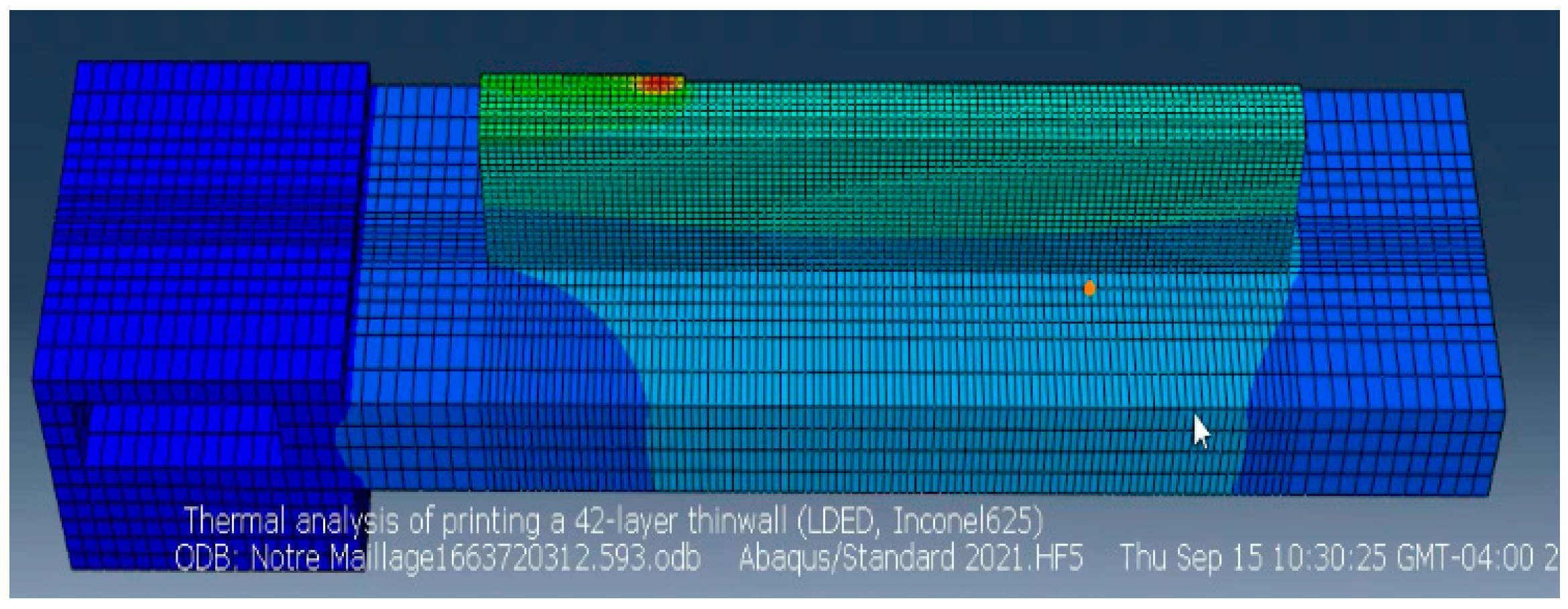
Figure 8 shows the geometry of the model and the FE mesh generated by Abaqus 2022 for the thermomechanical analysis of an FA part. The same mesh is used in the structural analysis and the thermal analysis. The mesh contains 55,531 nodes and 46,796 hex-8 elements, which are selected [30]. The element volume of the deposited material is 1 mm × 1 mm × 0.87 mm (length × width × height). A three-dimensional thermomechanical coupling is applied where the thermal analysis releases laser energy that is applied to the structural model of the part.

3.2.2. Material Proprieties

Due to the hardening effect of molybdenum and its high resistance to fatigue corrosion, high temperature, and pressure, Inconel 625 was used as a structural material in this study [31]. The detailed chemical composition of this alloy is presented in Table 3.
The thermal dependency properties of Inconel 625 in a range of [20–870 °C] are provided in Table 4. The density of Inconel 625 is fixed at 8.44 × 10⁻⁶ g/mm3.
Reference [32] reports that the approximate value of emissivity, ε, is equal to 0.28 because emissivity varies with the surface finish, while the convective heat transfer coefficient, h, is taken as 18 W/m2/°C. The physical properties are presented in Table 5.

4. Results and Discussion

Thermomechanical models for AM analysis have been validated in previous work to optimize material properties and process parameters but for different geometries and parameters [33,34,35,36]. In addition, the numerical results have been compared with experimental measurements reported in [18] to ensure AM simulation accuracy. The heat source fuses the powder and substrate to form a molten pool, but with the displacement of the laser, the melting solidifies and cools down. The strength of the layers decreases due to an increase in the temperature gradient because of the slowing down of thermal conduction. During the cooling process, the upper layer is plastically compressed, inducing thermal deformation and producing compressive stress (Figure 9). As a result, and with the absence of external mechanical stress, reverse bending occurs in the opposite direction to the laser. Then, compressive stress is formed inside the deposited layer, and tensile stress is formed at the end of the part.

4.1. Model Validation

4.1.1. Thermal Results

The thermal profiles and the model’s reliability were calculated for different printing strategies and compared to the benchmark Abaqus and experimental measurement predictions. The temperature is highest at the center of the melting zone but gradually decreases as it moves away from the center. The thermal cycle is the evolution of the temperature over time. The corresponding measured temperature history is presented in Figure 10. Curves show the temperature results during the printing of the mesh at three nodes corresponding to three thermocouple positions on the base plate (substrate).
Note that while thermocouples 1, 2, and 3 are located at different positions on the substrate, they record different thermal histories. Thermocouple 1, TC1, at the free end of the substrate, shows a lower peak temperature than TC2.
The recorded temperature of the TC2 (620 °C) sensor is about 115 °C higher than the values recorded for TC1 (505 °C). TC3 shows a lower peak temperature than TC2. The recorded temperature of the TC2 (620 °C) sensor is about 190 °C higher than the values recorded for TC3 (430 °C). The temperature recorded by sensor TC1 (505 °C) was about 75 °C higher than the value recorded by TC3 (430 °C). At the beginning of printing, the temperature of the melting zone in the first layers was lower than the temperature of the melting zone in the following layers due to heat loss through conduction in the substrate (26 °C). Note that the temperature on the substrate increases during the first third of printing; then, it decreases as the heat source moves away from the thermocouple location due to heat loss through convection and radiation.
According to Figure 11, the movement of the laser in the numerical model and the experiment causes peak curves during the deposition of the layer.
Discrepancies are attributed to the simplified hypothesis in defining the thermal boundary conditions during construction and a lack of precision in the definition of heat radiation and convection values. However, good agreement between the experiment and the numerical model results are depicted. The maximum temperature values at each thermocouple for all cases are gathered in Table 6.
Thermocouple readings vary depending on the measurement location. The highest temperature, measured at the substrate’s center (TC2), contrasts with the lowest temperature at the free end (TC1). Notably, the numerical model predicts a peak temperature (TC1) of around 505 °C. Conversely, the experiment reached 510 °C compared with the benchmark model’s 480 °C peak. This translates to a 30 °C difference (6.25% error) between the experiment and the numerical model. In contrast, the difference between the experimental and numerical results is minimal (around 5 °C or 1% error) for other locations, indicating good agreement.

4.1.2. Distortion Prediction Using Thermal–Mechanical Coupling

Following thermal analysis, the temperature history at each node of the finite element model is incorporated as thermal stress into the subsequent mechanical analysis. By using the same material properties for both the substrate and the part, this approach enhances the accuracy of distortion prediction during numerical simulations. Consequently, the temperature field within the melting zone achieves dynamic stability in terms of shape and size, leading to consistent thickness and width in the deposited layer. Figure 12 depicts the distortion distribution in the x- (longitudinal), y- (transverse), and z- (thickness) directions.
Svetlizky et al. [10] found that the distortion of DED Inconel 625 parts depends on the number of deposition layers and the initial substrate temperature. When the substrate and the deposited layer are combined, the temperature gradient is significant, which allows for an increase in residual stress. This is why the first layer is responsible for 50% of all distortions [37].
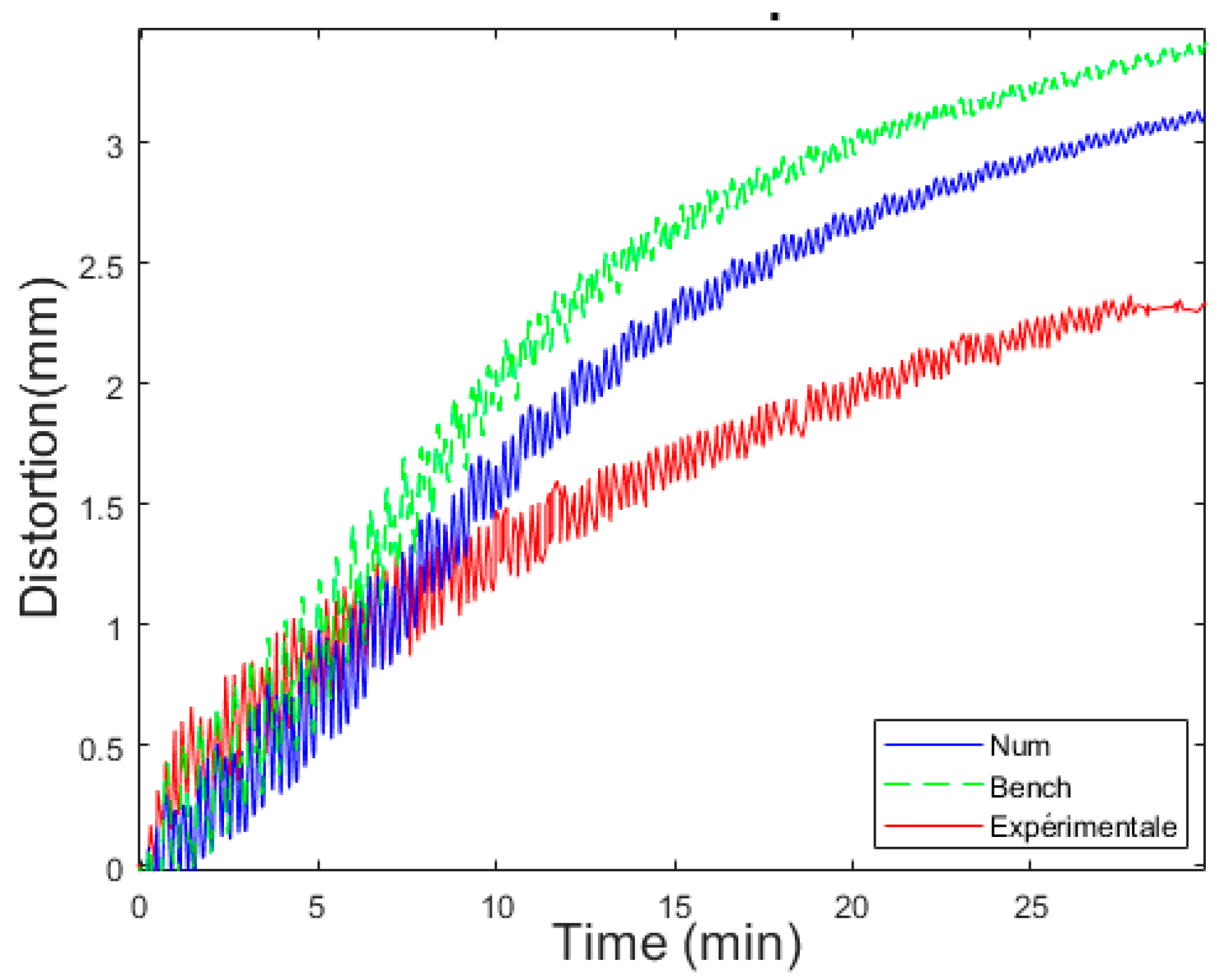
Figure 13 compares the evolution of distortion in the substrate obtained by the simulation of the benchmark Abaqus, the experimental results, and the numerical model. At the beginning of the printing process, the initial negative deviation of the first layer is notably higher than the other layers; it is about −0.29, caused by the wide thermal gradient between the building material and the substrate. The laser movement causes peaks in all curves of the numerical and experimental simulations during the layer deposition; it depends on the distance between the laser and the sensor.

4.1.3. Stress Distribution

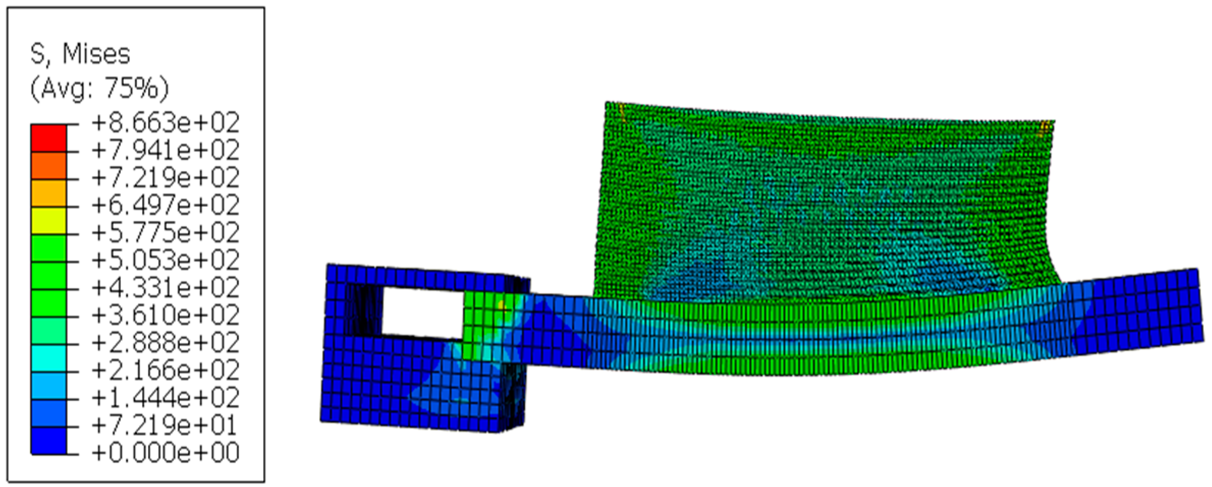
The mesh structure of the mechanical model is the same as that of the thermal model. In addition to in situ distortion measurements, stress distribution during various deposition processes was monitored. A representation of the residual stress distribution after cooling is in Figure 14.
As depicted, the cloudy map of the thermal stress distribution is provided after the deposition of 42 layers. At the beginning of the material melting, the stress is very negligible. The increase in the temperature gradient compensates for the thermal stress, which exceeds the yield strength to produce plastic deformation [38]. During cooling, the solidified metal creates the phenomenon of shrinkage, which gradually induces thermal stress.
After cooling, the thermal stress becomes stable, and residual stress is finally formed. The build-up of residual stresses negatively affects the product’s mechanical properties [39]. Due to the difference in thermal expansion values, shrinkage is formed after cooling between the deposited layer and the substrate, which implies that the maximum stress is equal to 866 MPa.

4.2. Effect of Zig-Zag Strategy

Laser scanning patterns are implemented using a series of events replicating the movement of the laser scanning strategy. The main difference between the standard method and the present one is the direction of the printing strategy, which may modify the results. As the laser moves away from the melt region, the temperature decreases gradually, and the melt solidifies and shrinks. Figure 15 shows this strategy’s laser path used for all deposit layers.

4.2.1. Thermal Results

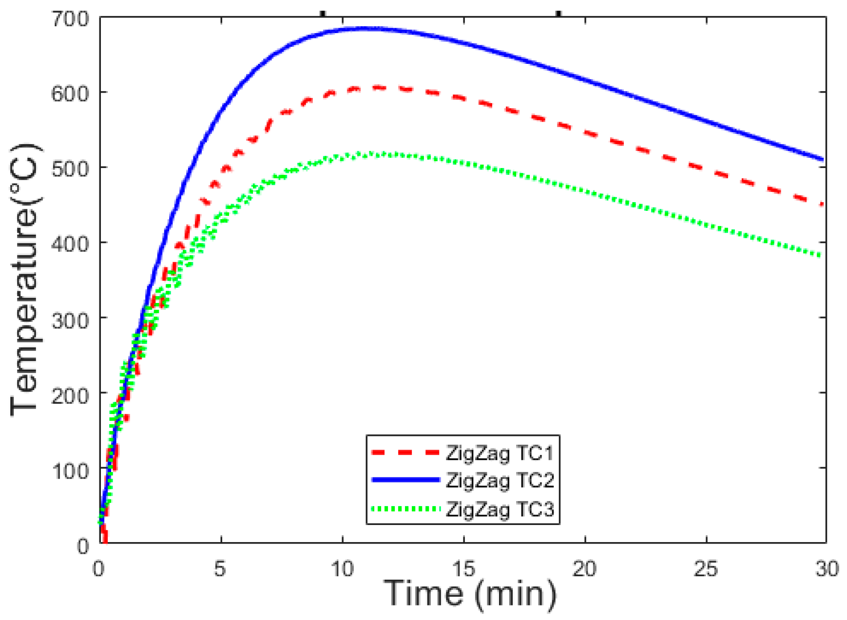
The thermal cycle is the evolution of the temperature over time. Figure 16 shows the temperature evolution of three thermocouples, TC1, TC2, and TC3, obtained from the numerical model measurements of this strategy along the z-direction.
As depicted in Figure 16, the temperatures recorded by each thermocouple of the thermal results of Zig-Zag’s strategy have many peaks in the curves, which was caused by the movement of the laser during the deposition of the layer. The first layer’s temperature is lower than other layers due to the conduction of the substrate. It can be observed that the recorded temperature of TC1 (610 °C) is about 100 °C higher than the values recorded at 510 °C, while the recorded temperature of TC2 (680 °C) is about 70 °C higher than the values recorded for TC1 and about 170 °C higher than the values recorded for TC3. This is due to the different locations of each thermocouple showing different trends and peak temperatures. Note that the highest temperature is measured at the center of the substrate, corresponding to TC2, while the next highest temperature is measured at the free end of the substrate, corresponding to TC1. Finally, the lowest temperature is measured at the clamped end of the base plate, corresponding to TC3.
As shown in Figure 17, the thermal fields of this strategy model are compared with the thermal fields of the numerical model.
In addition, several peaks are depicted in all curves caused by the movement of the laser during the deposition of the layer. The numerical thermal results are comparable to the experimental thermal results with the Zig-Zag strategy. Little discrepancies could be explained by the direction of the printing strategy, as the lengths of both strategies are not the same.
Note that each thermocouple shows different curves and peak temperatures depending on where the temperature measurement is taken. As shown in Figure 15, from the differences curves, it can be observed that the highest temperature can be measured at the center of the substrate in the results of these two strategies, corresponding to TC2, while the lowest temperature can be measured at thermocouple 3 (TC3).
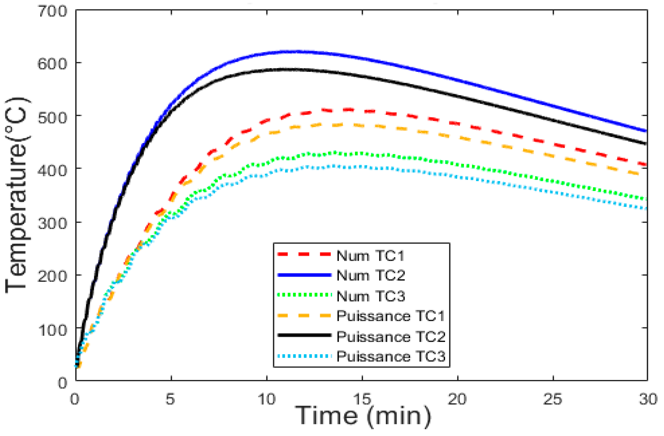
The maximum temperature recorded by each thermocouple for all cases is shown in Table 7. One can conclude that the printing strategy significantly influences the temperate gradient as the path of the heat source is longer, resulting in high cooling and a greater rate of temperature gradient.

4.2.2. Distortion Results

Once the thermal model is complete, the thermal history is imported into the mechanical analysis as a predefined field to advance distortion prediction. The power of the laser is permanently transmitted from the layers’ deposition to the substrate, provoking distortion due to thermal expansion. After the cooling process, the material stiffness is recovered due to the decrease in temperature. Figure 18 describes the distorted shape of the Zig-Zag strategy.
This large distortion is caused by the heat source on the cold substrate, which generates large thermal gradients. However, during the first initial layers of the DED process, the cold substrate quickly absorbs the heat input, which reduces the actual size of the molten pool, leading to reduced layer thickness during the metal deposition.
As shown in Figure 19, the curve variations were caused by the regular movement of the laser on the scan path during deposition. Therefore, this magnitude decreases slowly with the laser’s distance from the sensor node. At the beginning of the printing process, the numerical model and the Zig-Zag strategy have the same value of negative deviation at the first layer, about −0.29 mm, because of the use of the same heat source power (2000 W). It can be seen in this figure that the recorded peak distortion at the node of the LDS is about 3.1 mm for the numerical model, whereas the Zig-Zag result reached a peak distortion of 3.5 mm. In this case, it has been proven that there is an increase of 10% in the Zig-Zag strategy that can attributed to distortion. Indeed, the Zig-Zag strategy produces more deposition paths and pause times for the laser heat source, such that the path of the heat source is longer, which results in high cooling and a greater rate of temperature gradient, ultimately inducing more significant deflection.

4.2.3. Stress Distributions

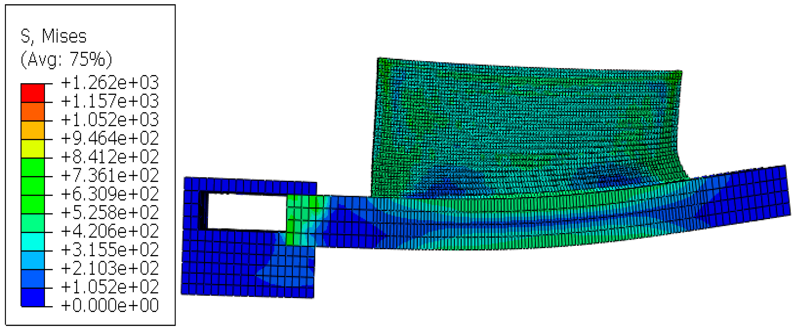
Residual stress was achieved using a Zig-Zag scan while depositing the layers. As the Zig-Zag strategy may create more deposition paths, rotations, and pauses in the laser heat source, the path of the heat source becomes longer, resulting in high cooling and a larger temperature gradient, eventually leading to greater deformation and stress. Figure 20 shows the residual stress shape.
The thermal stress depends on the temperature gradient. As the temperature gradient is too large, the thermal stress exceeds and produces plastic deformation. After the other layers’ deposition, the substrate temperature increases progressively to reach the equilibrium state between heat flow and heat diffusion. It finally stabilizes the maximum stress after cooling at about 1262 MPa, located at the junction of the printing part and the substrate due to the large temperature gradient.

4.3. Effect of Low-Power Strategy

The standard scan strategy was also used for the second optimized strategy when decreasing the power of the heat source from 2000 W to 1650 W. Power consumption of 1650 W was sufficient to achieve the full penetration of the powders. The effect of decreasing the laser power changed the depth at which the melting profile began.

4.3.1. Thermal Results

The thermal cycle is the evolution of the temperature over time. The corresponding measured temperature history of this strategy is presented in Figure 21. Temperature results are shown during the printing of the low-power strategy at three nodes that correspond to the three thermocouple positions on the substrate. The highest temperature is measured at the center of the substrate (TC2). TC3, placed at the clamped end of the substrate, shows a low peak temperature. At the beginning of the printing process, since the substrate is cold, the temperature of the melt zone is lower than that of the next layer due to conduction heat loss. Note that the temperature on the substrate increases during the first third of the printing process and then decreases as the heat source moves away from the thermocouple location due to heat loss owing to convection and radiation.
Figure 22 describes the influence of the power strategy on temperature distribution.
Temperature peaks in all the curves are caused by the movement of the laser during the deposition of the layer. The discrepancy between the numerical model and the thermal result of this strategy is explained by the decrease in the power of the heat source from 2000 W to 1650 W. Depending on where the temperature measurement is taken, each thermocouple trace shows a different curve and peak temperature.

4.3.2. Distortion Evolution

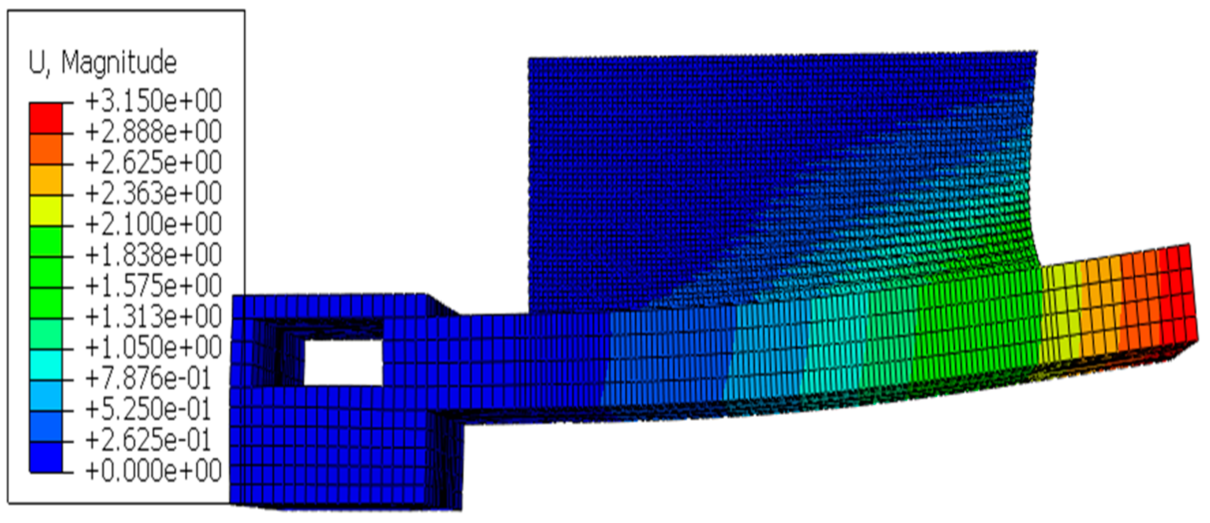
In this section, the influence of low-power methods on distortion is analyzed. Figure 23 shows the distribution of distortion after cooling. The distortion is decreased with the low-power strategy in the deposition of the layer, which can be explained by the decrease in the power of the heat source from 2000 W to 1650 W. This provides low cooling and a smaller rate for the temperature gradient, which induces deflection.
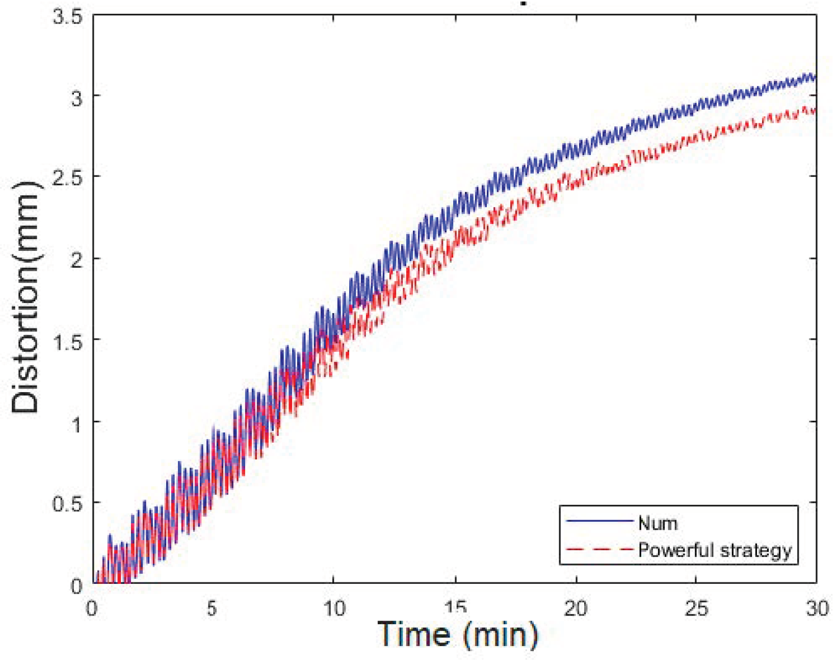
Figure 24 shows distortion–time evolution simulated via the numerical model and the low-power strategy. The laser movement causes peaks in all the curves of the numerical model and the low-power strategy during the deposition of the layer. At the beginning of the printing process, the initial negative deviation of the first layer is notably higher than the other layers. It is about −0.29 mm and −0.25 mm for the numerical model and the low power strategy, respectively, which is caused by the wide thermal gradient between the building material and the substrate.
It can be seen in this figure that the recorded peak distortion at the node of the LDS is about 3.1 mm for the numerical model, whereas the low-power result reached a peak distortion of 2.8 mm. In this case, when the power is decreased by 20%, the final residual distortion is also decreased by 10%.

4.3.3. Stress Results

Once the thermal model is complete, the thermal history is imported into the mechanical analysis as a predefined field to advance the prediction of thermal stress. The transient temperature is used as the thermal stress in the mechanical analysis. The same material was used for the substrate and the workpiece to accurately predict the stress evolution in the numerical analysis. As a result, the temperature field in the melting becomes dynamically stable in terms of shape and size, stabilizing the thickness and width of the deposited layer.
The deposited layer and the substrate combined in the region with the most incredible residual stress, while the residual stress gradually decreases further away from the deposited layer. As the temperature gradually decreases, the thermal stress gradually becomes stable and finally forms the residual stress after cooling, as shown in Figure 25. After the other layers’ deposition, the substrate temperature increases progressively to reach the equilibrium state between heat flow and heat diffusion. The maximum value is about 912 MPa at the boundary between the substrate and the deposited layer. However, the residual stress gradually decreases further away from the deposited layer.

5. Conclusions

This study employed a transient thermomechanical finite element model to investigate how various printing strategies affect distortion and residual stress during directed energy deposition. The model’s thermal profile predictions were validated through comparison with experimental measurements.
The findings revealed that the standard scan strategy with a 2000 W laser power resulted in significant distortion and residual stress due to a large temperature gradient.
The Zig-Zag strategy, while exhibiting similar initial distortion, ultimately produced higher peak distortion (a 10% increase) and residual stress (1262 MPa) because of its longer heat source path and faster cooling rate. Conversely, the low-power strategy, using a reduced laser power of 1650 W, effectively minimized distortion (a 10% decrease) and residual stress (down to 912 MPa) by creating a lower temperature gradient. This demonstrates that employing lower laser power compared with the standard setting can significantly improve the dimensional accuracy and mechanical properties of DED parts.

Author Contributions

A.B.H.: conceptualization, writing, original draft preparation, methodology, and visualization; H.M. (Hatem Mrad): funding acquisition, project administration, review and editing resources, writing, software, validation, methodology, formal analysis, and investigation; H.M. (Haykel Marouani): writing and review and editing resources; A.F.: supervision and review and editing resources; T.B.: supervision and review and editing resources. All authors have read and agreed to the published version of the manuscript.

Funding

This research was funded by the Ministère des Relations internationales et de la Francophonie of the Québec government. Appel à projets Québec-République tunisienne 2022–2023.

Data Availability Statement

No new data were created or analyzed in this study. Data sharing is not applicable to this article.

Conflicts of Interest

The authors declare no conflicts of interest. The funders had no role in the design of the study; in the collection, analyses, or interpretation of the data; in the writing of the manuscript; or in the decision to publish the results.

References

  1. Jafari-Marandi, R.; Khanzadeh, M.; Tian, W.; Smith, B.; Bian, L. From in-situ monitoring toward high-throughput process control: Cost-driven decision-making framework for laser-based additive manufacturing. J. Manuf. Syst. 2019, 51, 29–41. [Google Scholar] [CrossRef]
  2. Grasso, M.; Gallina, F.; Colosimo, B.M. Data fusion methods for statistical process monitoring and quality characterization in metal additive manufacturing. Procedia CIRP 2018, 75, 103–107. [Google Scholar] [CrossRef]
  3. Ahn, D.G. Directed Energy Deposition (DED) Process: State of the Art. Int. J. Precis. Eng. Manuf.-Green Technol. 2021, 8, 703–742. [Google Scholar] [CrossRef]
  4. Dass, A.; Moridi, A. State of the art in directed energy deposition: From additive manufacturing to materials design. Coatings 2019, 9, 418. [Google Scholar] [CrossRef]
  5. Yao, B.; Imani, F.; Yang, H. Markov Decision Process for Image-Guided Additive Manufacturing. IEEE Robot. Autom. Lett. 2018, 3, 2792–2798. [Google Scholar] [CrossRef]
  6. Al-Meslemi, Y. Predictive Modeling for Metal Additive Manufacturing: Key Characteristics and Porosity Characterization. Doctoral Dissertation, Université Paris-Saclay, Paris, France, 2021. [Google Scholar]
  7. Chen, Y.; Peng, X.; Kong, L.; Dong, G.; Remani, A.; Leach, R. Defect inspection technologies for additive manufacturing. Int. J. Extreme Manuf. 2021, 3, 022002. [Google Scholar] [CrossRef]
  8. Ren, W.; Mazumder, J. In-situ porosity recognition for laser additive manufacturing of 7075-Al alloy using plasma emission spectroscopy. Sci. Rep. 2020, 10, 19493. [Google Scholar] [CrossRef] [PubMed]
  9. Whiting, J.; Springer, A.; Sciammarella, F. Real-Time Acoustic Emission Monitoring of Powder Mass Flow Rate for Directed Energy Deposition. Addit. Manuf. 2018, 23, 312–318. [Google Scholar] [CrossRef] [PubMed]
  10. Svetlizky, D.; Das, M.; Zheng, B.; Vyatskikh, A.L.; Bose, S.; Bandyopadhyay, A.; Schoenung, J.M.; Lavernia, E.J.; Eliaz, N. Directed energy deposition (DED) additive manufacturing: Physical characteristics, defects, challenges and applications. Mater. Today 2021, 49, 271–295. [Google Scholar] [CrossRef]
  11. Khanzadeh, M.; Tian, W.; Yadollahi, A.; Doude, H.R.; Tschopp, M.A.; Bian, L. Dual process monitoring of metal-based additive manufacturing using tensor decomposition of thermal image streams. Addit. Manuf. 2018, 23, 443–456. [Google Scholar] [CrossRef]
  12. Michaleris, P.; Debiccari, A. Prediction of Welding Distortion A two-step numerical analysis technique was developed to predict welding- induced distortion and the structural integrity of large and complex structures. In Proceedings of the 12th International Symposium on Zirconium in the Nuclear Industry, Toronto, ON, Canada, 15–18 June 1998. [Google Scholar]
  13. Ninpetch, P.; Kowitwarangkul, P.; Chalermkarnnon, P.; Promoppatum, P.; Chuchuay, P.; Rattanadecho, P. Numerical Modeling of Distortion of Ti-6Al-4V Components Manufactured Using Laser Powder Bed Fusion. Metals 2022, 12, 1484. [Google Scholar] [CrossRef]
  14. Mughal, M.P.; Fawad, H.; Mufti, R.A. Three-dimensional finite-element modelling of deformation in weldbased rapid prototyping. Proc. Inst. Mech. Eng. Part C J. Mech. Eng. Sci. 2006, 220, 875–885. [Google Scholar] [CrossRef]
  15. Corbin, D.J.; Nassar, A.R.; Reutzel, E.W.; Beese, A.M.; Michaleris, P. Effect of Substrate Thickness and Preheating on the Distortion of Laser Deposited Ti–6Al–4V. J. Manuf. Sci. Eng. 2018, 140, 061009. [Google Scholar] [CrossRef]
  16. Knüttel, D.; Baraldo, S.; Valente, A.; Carpanzano, E.; Wegener, K. Height prediction in Directed Metal Deposition with Artificial Neural Networks. Procedia CIRP 2022, 113, 312–317. [Google Scholar] [CrossRef]
  17. Yang, Y.P.; Jamshidinia, M.; Boulware, P.; Kelly, S.M. Prediction of microstructure, residual stress, and deformation in laser powder bed fusion process. Comput. Mech. 2018, 61, 599–615. [Google Scholar] [CrossRef]
  18. Denlinger, E.R.; Michaleris, P. Effect of stress relaxation on distortion in additive manufacturing process modeling. Addit. Manuf. 2016, 12, 51–59. [Google Scholar] [CrossRef]
  19. Smith, J.; Xiong, W.; Yan, W.; Lin, S.; Cheng, P.; Kafka, O.L.; Wagner, G.J.; Cao, J.; Liu, W.K. Linking process, structure, property, and performance for metal-based additive manufacturing: Computational approaches with experimental support. Comput. Mech. 2016, 57, 583–610. [Google Scholar] [CrossRef]
  20. Marion, G.; Cailletaud, G.; Colin, C.; Mazière, M. A finite element model for the simulation of direct metal deposition. In International Congress on Applications of Lasers & Electro-Optics; AIP Publishing: San Diego, CA, USA, 2014; pp. 834–841. [Google Scholar] [CrossRef]
  21. Mi, G.; Li, C.; Gao, Z.; Zhao, D.; Niu, J. Finite element analysis of welding residual stress of aluminum plates under different butt joint parameters. Eng. Rev. 2014, 34, 161–166. [Google Scholar]
  22. Goldak, J.; Chakravarti, A.; Bibby, M. A new finite element model for welding heat sources. Metall. Trans. B 1984, 15, 299–305. [Google Scholar] [CrossRef]
  23. Goldak, J.A.; Akhlaghi, M. (Eds.) Thermal Analysis of Welds. In Computational Welding Mechanics; Springer: Boston, MA, USA, 2005; pp. 71–117. [Google Scholar] [CrossRef]
  24. Israr, R.; Buhl, J.; Elze, L.; Bambach, M. Simulation of different path strategies for wire-arc additive manufacturing with Lagrangian finite element methods Chair of Mechanical Design and Manufacturing. In Proceedings of the LS-DYNA Forum 2018, Bamberg, Germany, 15–17 October 2018. [Google Scholar]
  25. Wang, J.; Wang, Y.; Su, Y.; Shi, J. Evaluation of in-situ alloyed Inconel 625 from elemental powders by laser directed energy deposition. Mater. Sci. Eng. A 2022, 830, 142296. [Google Scholar] [CrossRef]
  26. Tsirkas, S.A.; Papanikos, P.; Kermanidis, T. Numerical simulation of the laser welding process in butt-joint specimens. J. Mater. Process. Technol. 2003, 134, 59–69. [Google Scholar] [CrossRef]
  27. Lundbäck, A. Finite Element Modelling and Simulation of Welding of Aerospace Components. Doctoral Dissertation, Luleå tekniska universitet, Luleå, Sweden, 2003; p. 50. [Google Scholar]
  28. Ulbricht, A.; Altenburg, S.J.; Sprengel, M.; Sommer, K.; Mohr, G.; Fritsch, T.; Mishurova, T.; Serrano-Munoz, I.; Evans, A.; Hofmann, M.; et al. Separation of the Formation Mechanisms of Residual Stresses in LPBF 316L. Metals 2020, 10, 9. [Google Scholar] [CrossRef]
  29. Dunbar, A.J.; Denlinger, E.R.; Gouge, M.F.; Simpson, T.W.; Michaleris, P. Comparisons of laser powder bed fusion additive manufacturing builds through experimental in situ distortion and temperature measurements. Addit. Manuf. 2017, 15, 57–65. [Google Scholar] [CrossRef]
  30. Benzley, S.E.; Perry, E.; Merkley, K.; Clark, B.; Sjaardama, G. A Comparison of All Hexagonal and All Tetrahedral Finite Element Meshes for Elastic and Elasto-plastic Analysis. In Proceedings, 4th International Meshing Roundtable; Sandia National Laboratories: Albuquerque, NM, USA, 1995; p. 13. [Google Scholar]
  31. Shoemaker, L.E. Alloys 625 and 725: Trends in Properties and Applications. Superalloys 2005, 718, 409–418. [Google Scholar] [CrossRef]
  32. Lu, X.; Cervera, M.; Chiumenti, M.; Lin, X. Residual Stresses Control in Additive Manufacturing. J. Manuf. Mater. Process. 2021, 5, 138. [Google Scholar] [CrossRef]
  33. Ivanov, S.; Artinov, A.; Zemlyakov, E.; Karpov, I.; Rylov, S.; Em, V. Spatiotemporal Evolution of Stress Field during Direct Laser Deposition of Multilayer Thin Wall of Ti-6Al-4V. Materials 2021, 15, 263. [Google Scholar] [CrossRef] [PubMed]
  34. Yan, Z.; Zou, X.; Li, S.; Luo, G.; Song, L. A Study on the Thermo-Mechanical History, Residual Stress, and Dynamic Recrystallization Mechanisms in Additively Manufactured Austenitic Stainless Steels. Metals 2022, 12, 1109. [Google Scholar] [CrossRef]
  35. Filho, C.M.; Caicedo-Silva, M.; Cervera, M.; Chiumenti, M.; Baiges, J. A Robust h-Adaptive Finite Element Framework for Industrial Part-Scale Thermal Analysis in Additive Manufacturing Processes. Eng. Comput. 2022, 38, 4791–4813. [Google Scholar] [CrossRef]
  36. Du, L.; Gu, D.; Dai, D.; Shi, Q.; Ma, C.; Xia, M. Relation of thermal behavior and microstructure evolution during multi-track laser melting deposition of Ni-based material. Opt. Laser Technol. 2018, 108, 207–217. [Google Scholar] [CrossRef]
  37. Lu, X.; Lin, X.; Chiumenti, M.; Cervera, M.; Hu, Y.; Ji, X.; Ma, L.; Yang, H.; Huang, W. Residual stress and distortion of rectangular and S-shaped Ti-6Al-4V parts by Directed Energy Deposition: Modelling and experimental calibration. Addit. Manuf. 2019, 26, 166–179. [Google Scholar] [CrossRef]
  38. Glaspell, A.; De la Peña, J.A.D.; Ryu, J.J.; Choo, K. Thermal Stress Characteristics of Dissimilar Joints Joining Ti-64 and CCM via Linear Friction Welding. Energies 2022, 15, 5588. [Google Scholar] [CrossRef]
  39. Mukherjee, T.; Zhang, W.; DebRoy, T. An improved prediction of residual stresses and distortion in additive manufacturing. Comput. Mater. Sci. 2017, 126, 360–372. [Google Scholar] [CrossRef]
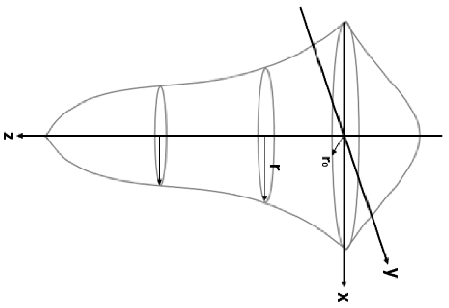
Figure 1. The rotary Gaussian model.
Jmmp 08 00116 g001
Figure 2. Distribution of the Goldak model.
Jmmp 08 00116 g002
Figure 3. Model geometry: clamp, substrate, and part to fabricate.
Jmmp 08 00116 g003
Figure 4. Location of sensors.
Jmmp 08 00116 g004
Figure 5. Laser path during the deposition. (a) Layer n: Laser path right to left, (b) Layer n + 1: Laser path left to right.
Jmmp 08 00116 g005
Figure 6. Flowchart of a thermomechanical simulation.
Jmmp 08 00116 g006
Figure 7. Material activation.
Jmmp 08 00116 g007
Figure 8. The geometry of the model and the finite element mesh.
Jmmp 08 00116 g008
Figure 9. Internal working principle of deformation.
Jmmp 08 00116 g009
Figure 10. Evolution of temperature versus time of the numerical model.
Jmmp 08 00116 g010
Figure 11. Validation of the temperature of the numerical model.
Jmmp 08 00116 g011
Figure 12. Displacement distribution.
Jmmp 08 00116 g012
Figure 13. Evolution of distortion in numerical, experimental, and Abaqus benchmark models.
Jmmp 08 00116 g013
Figure 14. Stress distribution.
Jmmp 08 00116 g014
Figure 15. Laser path of the Zig-Zag strategy.
Jmmp 08 00116 g015
Figure 16. Temperature evolution with time.
Jmmp 08 00116 g016
Figure 17. Influence of strategy on the temperature of the numerical model.
Jmmp 08 00116 g017
Figure 18. Distribution of distortion.
Jmmp 08 00116 g018
Figure 19. Influence of the strategy on the distribution of numerical model distortion.
Jmmp 08 00116 g019
Figure 20. Stress distribution of this strategy.
Jmmp 08 00116 g020
Figure 21. Temperature evolution concerning time.
Jmmp 08 00116 g021
Figure 22. Influence of the low-power strategy on numerical model temperature.
Jmmp 08 00116 g022
Figure 23. Distribution of distortion after cooling.
Jmmp 08 00116 g023
Figure 24. Effect of the strategy on the distortion distribution up to 30 min.
Jmmp 08 00116 g024
Figure 25. Stress distribution.
Jmmp 08 00116 g025
Table 1. Goldak model parameters.
ParameterValue
Weld pool width, a2.0 mm
Weld pool depth, b1.1 mm
Forward weld pool, cf2.0 mm
Rearward weld pool, cr2.0 mm
Forward heat factor, ff1.0
Rearward heat factor, fr1.0
Exponent constant, n1.0
The laser beam spot size, D4 mm
Weld pool energy, Q2000 W
Laser scan speed, v10.6 mm/s
Table 2. Symbols and abbreviations.
DesignationSymbol
Strategy of standard modelNum
Experimental resultsExp
Simulation benchmark AbaqusBench
Strategy of power variationPower
Strategy of scan pattern for Zig-ZagZig-Zag
Laser displacement sensorLDS
Thermocouple 1 at the free end of the substrateTC1
Thermocouple 2 at the center of the substrateTC2
Thermocouple 3 at the clamp end of the substrateTC3
Table 3. Chemical composition (%) of assessed Inconel 625 [31].
ElementCrMoNbFeNi
Percentage (%)2293.53-
Table 4. Thermal dependency properties of Inconel 625 [18].
T
(°C)
Conductivity
(mW/(mm·°C))
Specific Heat
(mJ/(ton·°C))
α
(1/°C)
E
(MPa)
Yield Stress
(MPa)
209.94.10 × 1081.28 × 10–52.08 × 105493
20512.54.56 × 1081.31 × 10–51.98 × 105443
31514.14.81 × 1081.33 × 10–51.92 × 105430
42515.75.11 × 1081.37 × 10–51.86 × 105424
54017.55.36 × 1081.40 × 10–51.79 × 105423
65019.05.65 × 1081.48 × 10–51.70 × 105422
76020.85.90 × 1081.53 × 10–51.61 × 105415
87022.86.20 × 1081.58 × 10–51.48 × 105386
Table 5. The physical properties of Inconel 625.
ClampInconel 625
Density2.70 × 10−9 ton/mm3
Conductivity237 mW/(mm·°C)
Specific heat9.1 × 108 mJ/(ton·°C)
Elastic modulus70 × 103 MPa
Poisson’s ratio0.366
Thermal expansion coefficient2.31 × 10−5/°C
Solidus temperature1290 °C
Liquidus temperature1350 °C
Emissivity0.28
Film coefficient0.018 mW/(mm2·°C)
Feed rate16 g/min
Latent heat272 × 109
Table 6. The maximum measured temperatures.
Abaqus. BenchExp.Num. Model
TC1 (°C)480510505
TC2 (°C)565505620
Table 7. The maximum temperature of the Zig-Zag strategy.
Zig-ZagRef
TC1 (°C)610505
TC2 (°C)680620
TC3 (°C)510430
Disclaimer/Publisher’s Note: The statements, opinions and data contained in all publications are solely those of the individual author(s) and contributor(s) and not of MDPI and/or the editor(s). MDPI and/or the editor(s) disclaim responsibility for any injury to people or property resulting from any ideas, methods, instructions or products referred to in the content.