Article

Numerical Modeling of Cutting Characteristics during Short Hole Drilling: Modeling of Kinetic Characteristics

by
Michael Storchak
*,
Thomas Stehle
and
Hans-Christian Möhring
Institute for Machine Tools, University of Stuttgart, Holzgartenstraße 17, 70174 Stuttgart, Germany
*
Author to whom correspondence should be addressed.
J. Manuf. Mater. Process. 2023, 7(6), 195; https://doi.org/10.3390/jmmp7060195
Submission received: 8 October 2023 / Revised: 28 October 2023 / Accepted: 2 November 2023 / Published: 4 November 2023
(This article belongs to the Special Issue Advances in High-Performance Machining Operations)

Abstract

:
Analyzing the cutting process characteristics opens up significant opportunities to improve various material machining processes. Numerical modeling is a well-established, powerful technique for determining various characteristics of cutting processes. The developed spatial finite element model of short hole drilling is used to determine the kinetic characteristics of the machining process, in particular, the components of cutting force and cutting power. To determine the component model parameters for the numerical model of drilling, the constitutive equation parameters, and the parameters of the contact interaction between the drill and the machined material on the example of AISI 1045 steel machining, the orthogonal cutting process was used. These parameters are determined using the inverse method. The DOE (Design of Experiment) sensitivity analysis was applied as a procedure for determining the component models parameters, which is realized by multiple simulations using the developed spatial FEM model of orthogonal cutting and the subsequent determination of generalized values of the required parameters by finding the intersection of the individual value sets of these parameters. The target values for the DOE analysis were experimentally determined kinetic characteristics of the orthogonal cutting process. The constitutive equation and contact interaction parameters were used to simulate the short hole drilling process. The comparison of experimentally determined and simulated values of the kinetic characteristics of the drilling process for a significant range of cutting speed and drill feed changes has established their satisfactory coincidence. The simulated value deviation from the corresponding measured characteristics in the whole range of cutting speed and drill feed variation did not exceed 23%.

1. Introduction

In comparison with measuring methods used in practice, machining process modeling enables a deeper and more accurate assessment of the cutting process conditions and the phenomena accompanying this process in different cutting zones [1]. Based on numerical simulations of various machining processes, complex physical and mechanical interactions between the tool and the machined material as well as with the chip are identified, which subsequently serve as a basis for optimizing existing machining processes and developing new ones. Among the most significant advantages of numerical modeling in the cutting processes is the possibility to reduce the cost of prototyping and the number of experimental tests [2]. Finite element models have gained wide popularity as a powerful instrument for simulating various characteristics of cutting processes in adequate combination with analytical and empirical approaches [3].
Recently, considerable attention has been paid to the numerical modeling of spatial cutting processes in material removal. This applies substantially to machining processes with end tools, such as drilling and milling. The possibility to model spatial machining processes ensures a significant reduction in experimental costs. This is especially relevant when newly profiled surfaces [4,5] need to be machined. Such machining processes make up 40–60% of the total number of cutting processes and are therefore among the most common in modern manufacturing [1,3]. Machining processes with end tools are characterized by constantly changing conditions of contact between the tool and the machined material [6,7,8]. This significantly complicates the modeling method and necessitates the development of ways to carefully tune the modeling parameters as well as numerical implications and resulting effects. In addition, the numerical modeling of machining processes with end tools, in particular the modeling of drilling processes, is associated with a significant computing time and difficulty in generating reference points for model building.
One of the further research trends is certainly the development of numerical modeling techniques, in particular the modeling of short hole drilling processes by means of improving the methodology for determining the parameters of component models for the numerical cutting model. This is the focus of the present study.

2. Methods for the Determination of Kinetic Characteristics in Short Hole Drilling

The drilling process is one of the oldest material removal processes [9]. Drilling is one of the most important machining processes in metal cutting and accounts for approximately 30–50% of the total material removal processes [10]. A characteristic feature of this process is the presence of a hidden chip-forming zone so that the chip-forming process remains hidden from the observer [11]. In this regard, the determination of kinetic characteristics accompanying the drilling process is particularly difficult compared with other cutting processes. In this paper, kinetic characteristics are understood as characteristics that determine the regularities of physical bodies motion and their stress–strain state. The components of cutting forces and cutting power were selected as the studied kinetic characteristics. Methods for determining the kinetic characteristics of the drilling process as well as other machining processes are divided into experimental (see, e.g., [12]), analytical (see, e.g., [13]), and numerical modeling methods. Analytical and numerical modeling methods contribute to a deeper investigation of the drilling process and enable a better understanding of it. In comparison with experimental and analytical methods, the numerical modeling of drilling processes provides a detailed analysis of thermomechanical processes in the cutting zones hidden from the researcher. The building of commercial numerical simulation software products during the last decades has provided a robust tool for simulating various cutting processes.
Numerical models of drilling processes with different types of drills, such as spiral (helical) drills (see for example [14,15,16]), single-lip drills for deep hole drilling (see for example [17,18]), drills with indexable inserts for short hole drilling (see for example [19,20,21,22]), and other types of drills have been the subject of numerous studies. It takes considerable time (from several days to several weeks) to simulate the drilling process of different materials because numerical models of drilling are usually spatial models. Neugebauer et al. evaluated the simulation time of a 3D drilling model, which was found to be quite significant [6]. However, the cost of the time to simulate the drilling process characteristics has to be taken into account since the conditions of contact between the tool and the machined material during the drilling process change significantly from the periphery of the drill to its center. In this regard, it is not possible to simplify numerical models of the drilling process by switching to two-dimensional finite element models [23]. The long simulation time of the drilling process is caused by a significant and, in some cases, a very large finite element number of the modeling objects (usually the workpiece). This is due to the need to use a very fine mesh in the cutting zones and adjacent areas of the machined material where significant stresses occur. The smallest number of finite elements of the workpiece mesh that provides a given accuracy in modeling the drilling process ranges from about 16,000 elements [24] to 30,000 elements [25] and higher. Gardner and Dornfeld believe that the number of workpiece elements should not exceed 50,000 to ensure sufficient accuracy in modeling kinetic characteristics [26]. Nevertheless, a much larger and sometimes enormous number of finite elements is often used. Klocke et al. performed a simulation of a deep drilling process with a single-lip drill by means of a workpiece model meshed into 100,000 elements [17]. Gyliene et al. used a workpiece model composed of 200,000 SPH particles to simulate the drilling process with a mesh-free numerical method called smoothed particle hydrodynamics (SPH) [27]. When modeling the machining process of Inconel 718 nickel alloy with spiral drills by using a combination of computational fluid dynamics (CFD) and the finite element method, Oezkaya et al. applied 6 million elements in the fluid model [28].
A significant amount of research on the numerical modeling of drilling processes consists of machining studies with spiral (also called helical or twist) drills (see, e.g., [29]). Moreover, a significant part of these studies deals with modeling the drilling process of titanium alloys and hard-to-machine materials. Parida [30] achieved a good agreement between measured and modeled cutting forces as well as torque during the drilling of Ti6AlV4 titanium alloy with carbide tools. A study of temperature distribution in a Ti6Al4V titanium alloy workpiece during drilling process was carried out by Kumar et al. [31]. Studies also focused on the temperature regime in the drilling process of titanium alloy using spiral drills were conducted by Patne et al. [32] as well as Li and Shih [33]. To significantly reduce the simulation time, Matsumura and Tamura proposed a hybrid finite element model of the drilling process, which is a combination of planar and 3D FEM models [34]. The coupling between the models was achieved by energy matching. In the study by Muhammad et al. [35], the numerical modeling of the titanium alloy drilling process was carried out with an additional energy input by means of heating the machined material to reduce its strength during the cutting process. Bonnet et al. presented a mixed numerical experimental approach to verify the multi-scale numerical model they developed [36]. This model ensured a more accurate determination of thermomechanical loads during the drilling of titanium alloys. The analysis of equivalent stresses and temperature distribution in the machined material using a finite element model for drilling Ti6Al4V titanium alloy was the subject of a study by Yang and Sun [15]. The satisfactory functionality of the FEM model was realized using the purposeful parameter determination of the triad of constituent models, material model, friction model, and damage model, of the machined material. Bücker and colleagues proposed a finite element model for drilling Inconel 718 nickel alloy using carbide drills with modified flank faces [37]. The wear of TiAIN-coated carbide drills during the drilling of Inconel 718 nickel alloy studied by Kolahdoozan et al. [38] using a three-dimensional numerical cutting model. Abouridouane et al. proposed a three-dimensional finite element model for the microdrilling of two-phase ferrite-perlitic carbon steels [39]. The constitutive equation describing the behavior of the machined material under thermomechanical loading by the tool was developed for this model. The influence of the machined material microstructure was taken into account in this equation. Ucun received adequate agreement between the measured and simulated kinetic characteristics in the drilling process of aluminum alloy Al7075-T6 [40]. A computational fluid dynamics (CFD) model was proposed by Oezkaya et al. to study the flow velocity and pressure of the cooling lubricant during drilling with twist drills of AISI 316L steel [41]. Girinon et al. proposed a finite element model to estimate the distribution of the residual stresses in AISI 316L steel after the drilling process with spiral drills [42].
The numerical modeling of the drilling process with single-lip drills, mainly designed for the production of deep holes, provides significant support for the development of this machining process. Along with the determination of the main characteristics of the cutting process, this modeling is made possible by the evaluation of the regularities regarding chip formation and chip removal from the cutting zone. Klocke et al. developed a three-dimensional finite element model of the deep hole-drilling process for AISI 4150 steel with single-lip drills [17]. The Johnson–Cook constitutive equation was used to characterize the material model. Guski and colleagues proposed a three-dimensional FEM model of deep hole drilling with single-lip drills [18]. The combined Euler–Langrangian method was applied in the model development. The comparison of measured and modeled characteristics of the cutting process proved the validity of the developed model. The subject of a study by Oezkaya et al. [43] was the simulation of the chip-forming process for Inconel 718 nickel alloy in the microdrilling of deep holes with single-lip drills. With the developed model, it was possible to evaluate the influence of the cooling lubricant flow on the removal of the generated chips. A study by Fandiño et al. [44] examined the kinetic and thermal characteristics in the drilling process of 42CrMo4 steel (AISI 1040) with single-lip drills as well as the residual stress formation in the machined material.
The smoothed particle hydrodynamics (SPH) method, designed for numerical modeling of various physical processes, was successfully used in the simulation of the drilling process. Gyliene et al. used the SPH technique to simulate the behavior of the machined material during drilling with twist drills [27]. Tajdari and Tai used the same technique [45]. In this case, the tool was modeled using the finite element method. By comparing the simulation results obtained with the finite element method and the SPH method, they made it possible to sufficiently simulate the machined material behavior in the drilling process by means of the SPH method.
Drilling short holes with indexable inserts is one of the most energy-intensive machining processes. In this process, the cutting inserts and the tool body are subjected to considerable loads. Analyzing the kinetic characteristics of the machining process through its numerical simulation provides a good opportunity to optimize the cutting process and the tool design. One of the first works on the application of a finite element model for the drilling process to tools with replaceable cutting inserts was presented by Marusich et al. [46]. An explicit method was used to simulate the kinetic process characteristics. Confirmation of the developed model adequacy was achieved by good agreement between the measured and simulated values of axial force and torque. Kheireddine et al. developed a three-dimensional model of drilling with exchangeable inserts [47]. In this case, the studied influence of cryogenic cooling was modeled using the rapid heat transfer with a corresponding convective heat coefficient. D. Grinko and A. Grinko examined the effect of axial and momentary pulses on the deformed state of the machined material [48]. Svensson et al. used the coupled Eulerian–Lagrangian scheme to model the drilling process for tools with exchangeable inserts [49]. With the help of this finite element model, the machining process characteristics were simulated separately for the inner and outer cutting inserts. Jiang et al. also simulated the characteristics of the drilling process for drills with separate inner and outer exchangeable inserts by means of the developed finite element model [50]. This study was carried out to evaluate the effect of cutting modes on the radial force acting on the tool during machining.
If the simulated values of the characteristics in the cutting process are similar to the real values and conform to the thermomechanical phenomena occurring in the cutting zones, the following triad model parameters are correctly determined and selected: the machined material model, the contact interaction model between the tool and the machined material (friction model), and the machined material fracture model, which all are components of the numerical cutting model.
Various constitutive equations applied as a material model have been used to describe the machined material behavior during the cutting process [51]. The most common one is the Johnson–Cook constitutive equation, which has been very often used in numerical models of the cutting process [52]. The application of the machined material model in the form of this equation has been mainly used in three-dimensional finite element models of material machining with end tools, in particular, models of drilling [53,54], milling [55,56], and other cutting processes. Moreover, the parameters of the constitutive equation were mostly taken from previously conducted studies, for example, those found in [57,58]. In some investigations, the simulation results of the orthogonal cutting process [59,60], as a simplified case of the spatial cutting process, have been used to determine the parameters of the constitutive equation. The constitutive equation parameters were also determined based on the analysis of various models [61]. In addition, various modifications of material models have been used, e.g., [59,62,63]. Experimental data (see, for example, [64]) were used as target values of the cutting process characteristics. To determine the parameters of contact interaction between the tool and the machined material [65], previously conducted studies on the estimation of friction parameters [54,56], as well as heat flows in the cutting zones [66] have been used in the vast majority of cases. For the numerical modeling of cutting processes with hard-to-machine materials, such as, for example, titanium and nickel alloys, it is necessary to know the fracture parameters of the machined material [67]. The same characteristics are needed for modeling the drilling processes of various non-metallic heterogeneous materials, such as composite materials [68]. They have been determined using the energy criteria of material damage [68,69,70] or by means of results comparing the shape and size of the generated chips [56,62,63].

3. Materials and Methods

The numerical modeling of the drilling process can only be carried out in spatial terms since the cutting conditions along the tool cutting edge are not constant. Apart from the cutting speed, which decreases linearly with decreasing cutting radius, the contact conditions of the tool with the machined material and with the chip change as well. This leads to a significant gradient in the degree of strain, strain rate, and temperature along the drill cutting edge. Consequently, when it is necessary to carry out numerical simulations of such a cutting process, the model triad describing the behavior of the machined material (material model, friction model, and damage model) must take into account this wide variation range.
The short hole-drilling process is carried out with two cutting inserts, e.g., carbide inserts: an outer and an inner one [19,21,48]. The outer insert cuts the machined material located between the wall of the produced hole up to about half of the hole radius. The inner insert removes the remaining machined material. The average cutting speed of the outer insert is significantly higher than the average cutting speed of the inner insert. This difference in cutting speed of the outer and inner inserts leads naturally to the above-mentioned different cutting conditions. In order to account for different cutting conditions, the material model and friction model parameters were determined separately for either insert in this study. Subsequently, similarly named parameters were combined into a single generalized parameter by finding the intersection of model parameter value sets [71]. The parameters of the above-mentioned models were determined using the inverse method. The orthogonal cutting process was used for this.

3.1. Materials

The thermally treatable steel AISI 1045 was used as a machined material. The properties of this steel required for finite element models are presented in Table 1 (see the first row of the table).

3.1.1. Orthogonal Cutting

To determine the kinetic characteristics of the orthogonal cutting process, a special stand for orthogonal and oblique cutting research was used [74,75]. In Figure 1, a scheme of the orthogonal cutting process and a CAD scheme of a special setup for realizing the orthogonal cutting process together with an experimental setup for measuring the kinetic characteristics are shown. The setup table with the workpiece fixed on it, driven at a given cutting speed VC via a linear motor, is located on a bed from polymer concrete. On the bed, there is also a tool fixed in the toolholder with the possibility of vertical movement to set the specified depth of cut [74,75]. The kinetic characteristics of the orthogonal cutting process were applied as target values to determine the material model parameters and the friction model parameters and were further used for the numerical simulation of the drilling process [71,76]. The cutting forces were measured using a three-component dynamometer, type 9121, by Kistler. The workpiece had dimensions of 170 × 65 × 3 mm and was clamped using a special clamping device, which in turn was fixed onto the dynamometer. The orthogonal cutting process of AISI 1045 steel was realized using a tool with a clamped, exchangeable cemented carbide insert (SNMG-SM-1105, manufactured by Sandvik Coromant).
Table 1 summarizes the basic mechanical and thermal properties of carbide inserts. (see the second row of the table). The tool was fixed to the stand bed via a gantry. The tool rake angle was γ = 0°, the tool clearance angle was α = 8°, and the cutting edge radius was 20 µm. Through grinding of the tool clearance face, the specified cutting wedge geometry was ensured. Equal to the undeformed chip thickness, the depth of cut a varied at three levels: 0.1 mm, 0.15 mm, and 0.2 mm. To make sure that the material model parameters could be determined for different contact conditions of the tool with the machined material and that the contact conditions during short hole drilling could be reproduced for both external and internal cutting inserts, the cutting speed was chosen within a wide range of its value change for the experiments on the orthogonal cutting process. Accordingly, the cutting speed VC was varied at six levels: 12 m/min, 24 m/min, 36 m/min, 48 m/min, 96 m/min, and 144 m/min. The numerical values of cutting speeds were chosen so that the variable range included cutting speeds that would ensure the occurrence of a built-up cutting edge on the tool. In addition, the selected numerical values of cutting speeds guaranteed an integer value of the Péclet similarity criterion [77,78]. The value of this criterion varied from 5 to 60. This criterion was further used as a similarity criterion to compare cutting temperatures at different cutting speeds.
The orthogonal cutting process was performed as a dry cutting. The reliability of the measured experimental values of the cutting forces was ensured by repeating each cutting test (both during orthogonal cutting and drilling) at least 5 times. The minimum and maximum measured values of the cutting forces were used to determine the error bars. The confidence interval was chosen based on the analysis of the scatter in particular experimental values of the cutting forces. The value of the confidence interval was chosen to be 0.9. The average value of the measured data was used as a representative value of the measured data, since no significant differences were observed between the individual measured cutting force values.

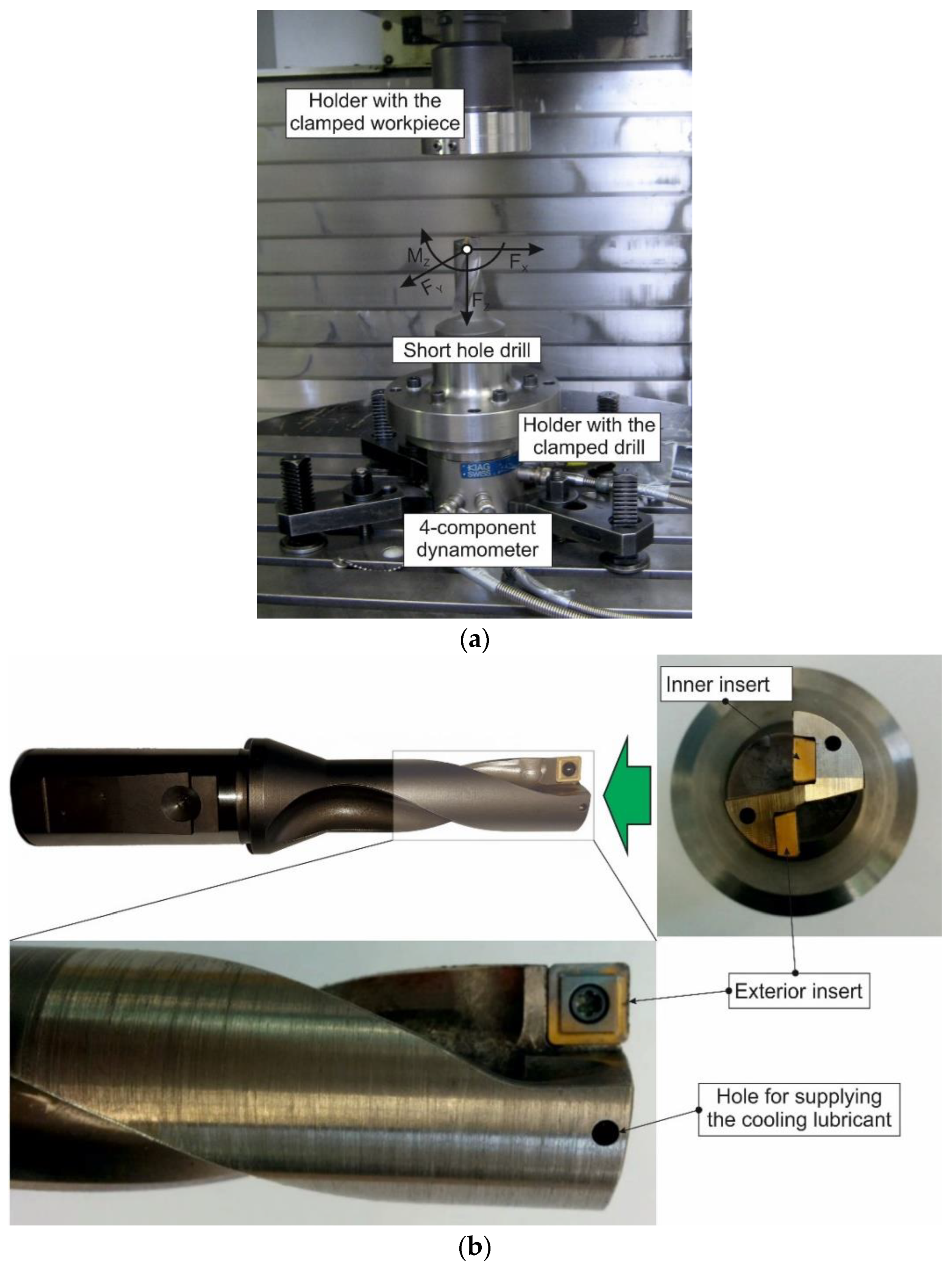
3.1.2. Short Hole Drilling

The experimental setup for examining the short hole drilling process is shown in Figure 2. The drilling process was carried out with a UWF 1202 H machining center by Hermle. A four-component dynamometer, type 9272, by Kistler and a mounted tool was fixed to the table of the machining center. The drill’s stationary clamping ensured that the cutting force components were constant, which in turn ensured the reduction in measurement errors. The cylindrical workpiece with dimensions Ø 60 mm × 30 mm manufactured from AISI 1045 steel was clamped in the HSK-A 63 cylindrical chuck holder, which was fixed in the center machining spindle. A short hole drill with carbide cutting inserts was used as a tool (see Figure 2b). The drill diameter was Ø 25 mm. To realize the cutting process, the short hole drill is equipped with two square carbide inserts: outer and inner. The outer insert removes the machined material located between the wall of the generated hole and up to about half of the hole’s radius (see Figure 2b). The inner insert removes the remaining machined material. The geometrical parameters of the outer and inner plates are the same. The cutting inserts were installed in the drill body in such a way that the rake angle was γd = 0° and the tool clearance angle was αd = 8°. The radius of the cutting edge rounding was about 20 µm, and the rounding radius of the insert tip was 4 mm. The thickness of the inserts was 5 mm. Equidistant to the cutting edges at a distance of 2 mm, a thickening of 1 mm was performed, designed for chip curling. Thus, the geometric parameters of the tool cutting insert for the realization of the orthogonal cutting process correspond to the geometric parameters of the drill cutting inserts. Three components of the resultant force, Fx, Fy and Fz, as well as the drilling torque Mz around the workpiece rotation axis were measured during machining (see Figure 2a). Feeding during drilling was carried out by moving the table with the drill to the workpiece in the Z-axis direction. The feed value was varied at three levels: 0.05 mm/rev, 0.1 mm/rev, and 0.15 mm/rev. The nominal cutting speed was also varied at three levels: 50 m/min, 100 m/min and 150 m/min. Statistical confirmation of the measured kinetic characteristics was achieved by multiple measurements under the same conditions of the cutting process. The minimum number of duplications for each measurement was 5.
The cutting modes for the orthogonal cutting process and short hole drilling are summarized in Table 2.

3.2. Methods

The parameter determination of the finite element model components for short hole drilling, namely the constitutive equation of the machined material behavior under the thermomechanical impact of the tool, the contact interaction model of the tool with the machined material and with the chip, and the fracture model of the machined material, was carried out through the numerical model of orthogonal cutting. Finite element models of the orthogonal cutting process and short hole drilling as well as simulations of these machining processes were performed in the DEFORM V 12.0 2D/3D™ software environment [79]. In numerical models of orthogonal cutting and short hole drilling, the cutting tools are taken as perfectly rigid. The machined material in the above models is assumed to be plastic, the regularities of its behavior under thermomechanical influence are described by the Johnson–Cook constitutive equation [51,52]. As a friction model, the Coulomb interaction of the tool with the workpiece and with the chip is assumed [65]. The determination of Coulomb friction parameters is based on the authors’ developed methodology [80] and is an extension of it. In the areas where contact interaction was expected, local friction coefficients corresponding to the contact conditions were established. The location of the friction windows used for the orthogonal cutting process is shown in Figure 3. A similar arrangement of friction windows was also used to simulate short hole drilling. The friction windows were used to enter these local coefficients [80]. Local friction coefficients, determined according to the method described in [80], were set in the areas of the tool where contact interaction was expected with the chip and with the workpiece. Friction windows were used to enter these local coefficients.
The chip formation during the cutting of AISI 1045 steel is a continuous process in which flow chip are produced [81,82]. In the case of flow chip formation, the software package used provided an algorithm for the automatic generation of the chip forming process [79]. In this regard, the developed FE cutting model did not utilize a special damage model for the machined material [67], such as in the machining of titanium alloys [76]. The separation of the machined material into chip and workpiece is ensured by the process of permanent remeshing of the workpiece mesh. The criterion for remeshing is a specified value of the maximum tool penetration into any of the workpiece mesh finite elements located in the vicinity of the tool boundaries (interference depth).

3.2.1. Orthogonal Cutting Process

The coupled mesh geometric 3D model of the orthogonal cutting process with simulated stresses in the workpiece and chip is presented in Figure 4. The same figure shows the model’s geometric dimensions, tool motion, initial and boundary conditions. The initial thermal conditions were determined by setting the room temperature (Tr) at the bottom and rear of the workpiece and at the top and rear of the tool. The depth of cut (undeformed chip thickness) a was set by the tool penetration into the workpiece in the negative direction of the Z-axis. The cutting width (workpiece width) was set equal to the value of w. The cutting speed VC was ensured with a tool movement in the negative direction of the X-axis. A characterization of the material model and friction model is presented at the beginning of Section 3.2.
To determine the generalized values of the material model parameters satisfying the kinetic characteristics of the cutting process in the studied range of cutting modes and machining conditions, the software procedure [71] was used, which is based on the authors’ previously published work and is an extension of it.

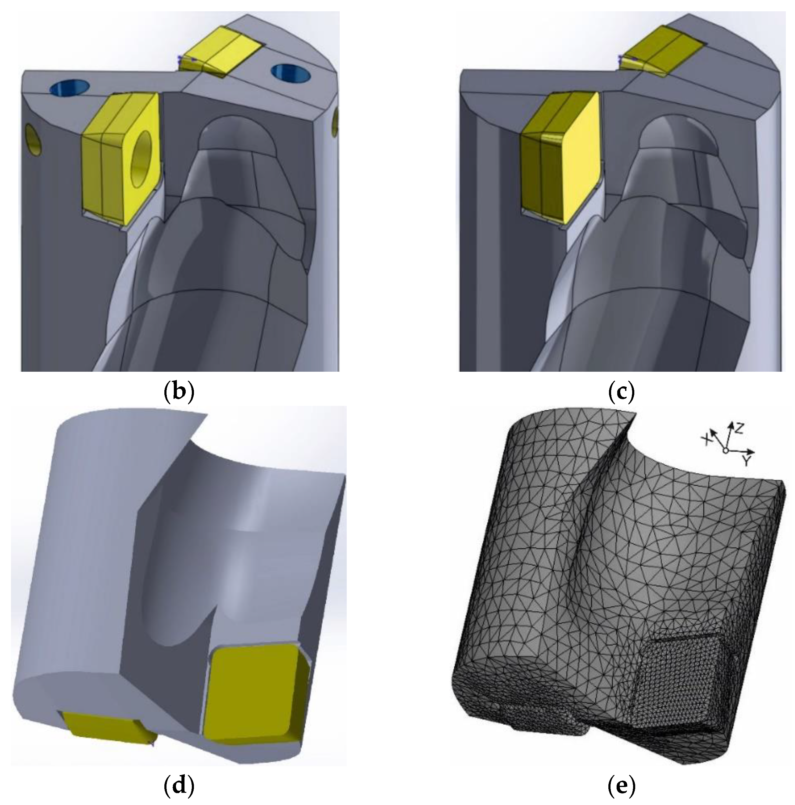
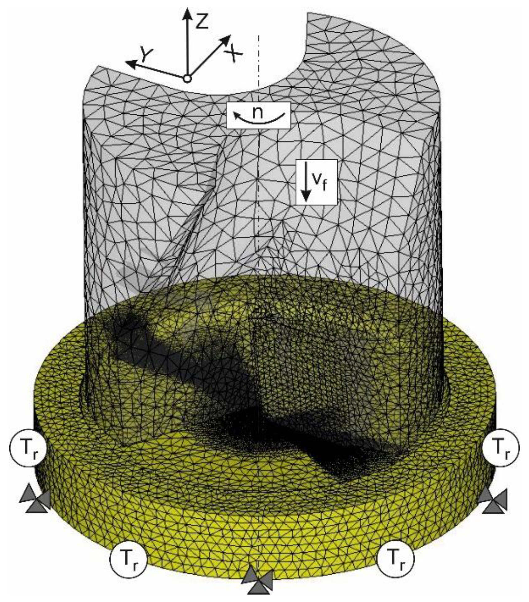
3.2.2. Short Hole Drilling

The numerical modeling of the kinetic characteristics for short hole drilling was performed using a three-dimensional finite element model. The significant part of the FEM model for a real cutting process using tools with a particular cutting edge, for example, shaped turning, drilling, milling, threading, and other similar processes, was the building of the tool model. The steps for building a short hole drill model are shown in Figure 5. In the first step, a general analysis of the drill’s CAD model was carried out—Figure 5a. The second step contained the analysis of possible simplifications of the tool design while maintaining the tool’s fundamental functional capabilities (see Figure 5b). A simplified CAD drill model is shown in Figure 5c. In the third step of the tool modeling, the tool’s geometrical shape was further simplified, and the CAD drill model was converted into a conformal format of the numerical simulation software (Figure 5d). The last step contained the partitioning of the geometric tool model into finite elements (see Figure 5e). This partitioning was carried out either directly in the numerical simulation software package or in a specialized program.
Figure 6 shows the initial geometric model of short hole drilling with mesh and boundary conditions. It also shows the mutual positioning of the tool and workpiece, their movements in space and relative to each other, and the boundary and initial conditions used.
The area of possible contact of the tool with the machined material in the cutting zones was divided into significantly smaller finite elements than other parts of the geometrical model. This ensured the necessary accuracy of modeling the stress–strain state of the machined material. By constraining the displacement of the workpiece in all coordinate directions, the boundary conditions of the finite element model were set. The drill was given an absolute rotary motion at a rotational speed n and a translational motion at a feed rate vf in the negative direction of the Z-axis. At the tool and workpiece boundaries, which were not in contact during the simulation the initial thermal conditions Tr were set.
The machined material model was defined using Johnson–Cook’s constitutive equation. The generalized parameters of the constitutive equation were determined by a numerical simulation of the orthogonal cutting model (see Section 3.2.1).

4. Results and Discussion

Experimental values of orthogonal cutting process characteristics were used as target values when conducting the DOE sensitivity analysis to identify the parameters of the material model and friction model: the constitutive equation parameters and friction parameters. The cutting force components were used as characteristics of the orthogonal cutting process. The DOE sensitivity analysis and the subsequent determination of the constitutive equation parameters and friction model parameters were performed by a numerical simulation of the orthogonal cutting process.
The validity estimation of the developed finite element model for short hole drilling was assessed by comparing the measured and simulated values of the cutting force components, drilling power, and cutting volume rate of the machined material during drilling.

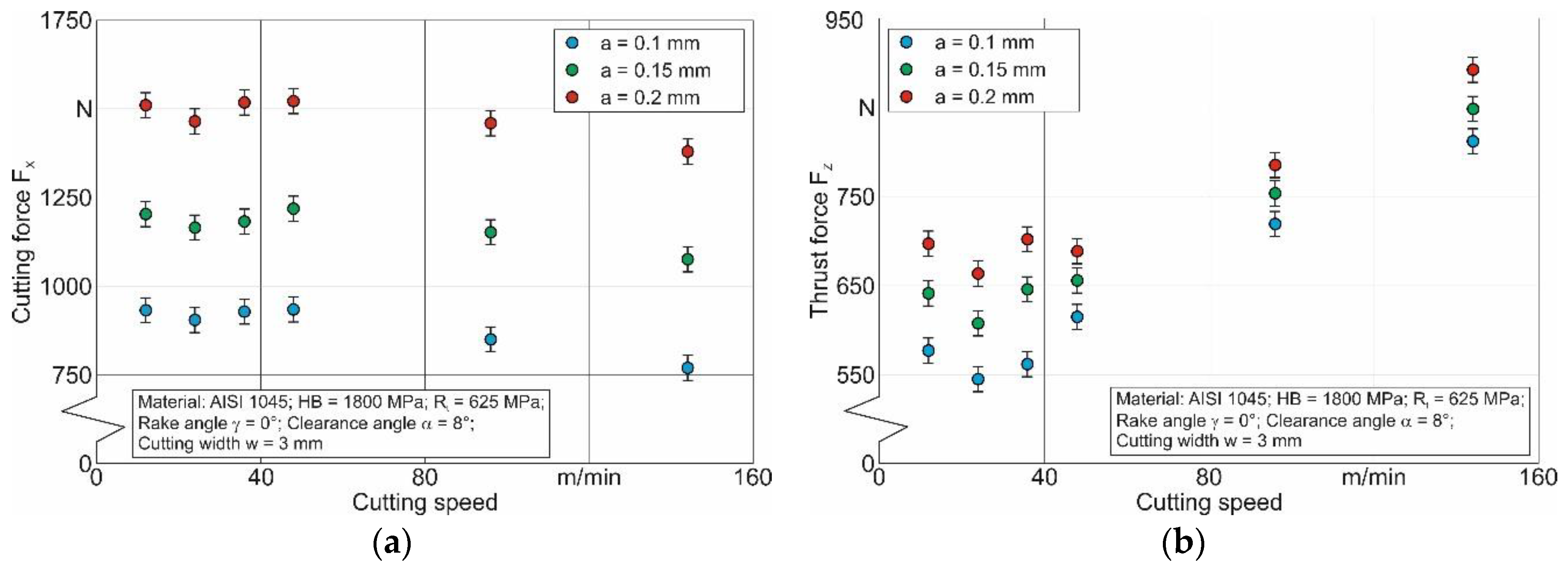
4.1. Orthogonal Cutting Process

The experimental values variation of kinetic characteristics as a function of cutting depth (undeformed chip thickness) and cutting speed during orthogonal cutting is presented in Figure 7. An increase in cutting depth caused the expected proportional increase in both components of cutting force FX and thrust force FZ (Figure 7a,b). The effect of cutting speed on the components of the cutting force was somewhat different. In the low-cutting-speed region from 12 m/min to 48 m/min, its increase caused an s-shaped change in both cutting force FX and thrust force FZ. Initially, the cutting force components were quite large (at VC = 12 m/min). When the cutting speed was subsequently increased (in this case to 48 m/min), the cutting forces decreased at first and then increased.
Such an influence of cutting speed in the region with low values is widely known [81,82]. This kind of cutting force variation could be explained by the formation of a built-up edge on the tool rake face. With further increases in cutting speed, the built-up edge was no longer formed and consequently did not influence the change in cutting forces. In the region of relatively high cutting speeds (above 50 m/min), in this case up to 144 m/min, an increase in cutting speed caused a slight decrease in cutting force FX (see Figure 7a). This change in cutting force FXwas was caused by the thermal softening of the machined material due to the increase in cutting temperature with increasing cutting speed VC. At the same time, this increase in cutting speed caused an increase in thrust force FZ (see Figure 7b). In all probability, the formation of this force component was mainly influenced by the machined material hardening caused by the effect of strain rate. In this case, the influence of the machined material hardening predominated over that of thermal softening.
In determining the constitutive equation and friction model parameters, the measured values of the cutting force components (see Figure 7) were used as target values for the DOE sensitivity analysis. The cutting force component FX was used as the objective value to determine the parameters of the Johnson–Cook constitutive equation. The measured values of the cutting force components FX and FZ were used to determine the friction model parameters. The constitutive equation parameters were established in three steps. In the first two steps, the constitutive equation parameters were determined separately for the outer and inner cutting inserts. In the orthogonal cutting process simulations, different values of average cutting speeds were used to carry out the DOE sensitivity analysis. These cutting speeds corresponded to the average cutting speeds of the outer and inner cutting inserts, respectively. For the particular tool used in the experimental tests and numerical modeling, the average cutting speed of the outer insert was 2.24 times greater than the average cutting speed of the inner insert. The value of the average cutting speed was determined by the average radii of the circles described by the cutting inserts during the drill rotation. Thus, different contact conditions were modeled for different cutting inserts. In the third stage, the generalized values of the constitutive equation parameters were determined by the parameters corresponding to the contact conditions of the outer and inner cutting inserts.
A similar algorithm was used to determine the local Coulomb friction coefficients in the plastic and elastic areas of the secondary cutting zone and in the tertiary cutting zone [80] separately for the outer and inner cutting inserts. Then, the generalized values of the indicated local friction coefficients were determined. Generalized local friction coefficients were set in the FEM cutting model in the plastic and elastic regions of the secondary cutting zone and in the tertiary cutting zone by means of friction windows [80].
Using the developed methodology presented in the previously published work of the authors [71], the generalized values of the constitutive equation parameters and Coulomb friction coefficients were determined. The generalized parameter values were established with this algorithm as the intersection of the parameter sets determined during subsequent DOE iterations. Table 3 shows the constitutive equation parameters and local friction coefficients separately for the outer and inner cutting insert as well as the generalized values of these parameters. These parameter values were used in the further simulation of the short hole drilling process.

4.2. Short Hole Drilling

Figure 8 presents the experimental results of the kinetic characteristics for the short hole-drilling process (cutting force components FX, FY, and FZ, and torque around the drill symmetry axis MZ) as well as of the integral characteristics of the drilling process (cutting power PC and cutting volume rate QC). This figure shows how the cutting modes of drill feed f and nominal cutting speed VC influenced these kinetic characteristics.
A significant increase in the cutting force components and torque was observed with increasing drill feed (see Figure 8a–d). This behavior of the cutting force components and torque was to be expected because the material volume removed from the workpiece increased accordingly as the tool feed increased.
The cutting speed effects on the kinetic characteristics of the drilling process had an opposite effect on the drill feed. The values of the kinetic characteristics FX, FY, and FZ, as well as MZ decreased monotonically with increasing cutting speed (see Figure 8a–d). In this case, the relative reduction manifested itself to a greater extent for the cutting force components FX and FY than for the axial force FZ and torque MZ. In all probability, the decrease in the value of the kinetic characteristics was due to the increase in cutting temperature, which enhanced the isothermal softening of the machined material [77,83].
The integral characteristics of short hole drilling (cutting power PC and cutting volume rate QC) increased monotonically with increasing drill feed f and cutting speed VC (see Figure 8e,f). In all probability, this kind of change in the integral cutting characteristics was due to the fact that the cutting speed was a co-multiplier in the equation for calculating the cutting power and that the feed rate was a co-multiplier in the dependence for determining the cutting volume rate. Thus, the effect of cutting speed as a co-multiplier predominated over the reduction in cutting force as a result of the isothermal softening of the machined material. Therefore, the cutting power increased with growing cutting speed (see Figure 8e).
The presented measurement results of the cutting force components and torque as well as the determined results of the integral characteristics were compared with the corresponding numerically simulated characteristics of short holes drilling. Various simulation characteristics of the short hole-drilling process (cutting force components, deformation-level development of the machined material during chip formation, stress values in the chip and machined material, and others) were used to establish the validity, reliability, and functional ability of the developed FEM model for the drilling process.
The modeling results of short hole drilling characteristics at cutting speed VC = 100 m/min and drill feed f = 0.1 mm/rev are shown in Figure 9, which shows how the modeled and measured values of the cutting force axial component FZ vary with the penetration depth of the drill into the workpiece. In addition, Figure 9 shows the effective deformation of the machined material and the formed chips, as well as the effective stresses in the chips and in the cutting zones. The change in the axial component FZ of the cutting force was characterized by two areas: the predrilling area and the stable drilling area (see Figure 9a). As the cone part of the drill penetrated the workpiece, the axial component FZ as well as other cutting force components increased from zero to a particular quasi-static value, which remained constant during the drilling process until the drill came out of the workpiece. The second area, which began when the simulation time was greater than 0.8 s, was characterized by a quasi-static, steady cutting process with the formation of flow chips produced by the outer and inner cutting inserts (see chip formation images in Figure 9a). The strain degree distribution of the machined material and in the chip, shown in Figure 9b, corresponded to a simulation time of 0.9 s. The accumulated deformation degree of the chip formed by the outer cutting insert and the adjacent region of the machined material ranged from about 7 in the region adjacent to the outer drill diameter to about 13.5 in the region adjacent to the inner end of the cutting insert. The accumulated deformation degree of the chip formed by the inner cutting insert and the adjacent machined material region ranged from about 13.5 to about 20 (see Figure 9b). The greatest accumulated deformation degree of chip and workpiece occurred at low cutting speeds up to a cutting speed of VC = 0. In addition, the distribution of effective stresses was characterized by a higher intensity in the cutting zones formed by the outer cutting insert (see Figure 9c). In the transition area from the primary cutting zone to the secondary cutting zone, the value of effective stresses was approximately 1000 MPa. Approximately half as much stress was observed in a similar area formed by the inner cutting insert.
Such a distribution of the main mechanical loads and deformations indicated a significant stress–strain state of the machined subsurface layers of the material as well as significant loads of the cutting inserts and the tool’s working part. In turn, this stress–strain state of the machined surface layers of the material caused a significant non-uniformity in the machined surface topography and in the physical as well as mechanical characteristics in the workpiece subsurface layers. This stress–strain state of the sub-surface layers of the machined material and the generated physical and mechanical characteristics of these layers contribute to the significant wear of the drill’s cutting inserts. These features of the short hole-drilling process indicated that a significant optimization in the machining process is possible and should definitely be considered in further studies.
The final verification of the developed finite element model’s ability to adequately simulate the kinetic characteristics of short hole drilling was performed by comparing the measured values of the cutting force components with the corresponding simulated values. In addition, the cutting power PC was also compared as it is an integral characteristic of the machining process. This kinetic characteristic includes all components of the cutting force, namely the resultant force and the speed mode of machining. Thus, the influence of various physical and mechanical processes taking place simultaneously during the cutting process could be determined by using the cutting power as a characteristic for comparing the kinetic characteristics of the machining process, which were determined by experiment and simulation.
Figure 10 shows the comparison results for the axial component FZ of the cutting force as well as the deviations between the measured and simulated characteristics. Figure 10a depicts the comparison results of the axial component FZ depending on the drill feed, whereas Figure 10b illustrates the comparison results of the axial component FZ depending on the nominal cutting speed. The simulated values of the axial component FZ deviated from the measured values of this component by about 9% and about 15.2%, respectively, when changing the drill feed from 0.05 mm/rev to 0.15 mm/rev. In this case, the simulated values of the FZ component were smaller than the measured values. In all probability, this difference was caused by an insufficient consideration of the hardening effect on the machined material in the process of its plastic and rate deformation. It was also possible that the isothermal softening of the machined material during the drilling process was not sufficiently reflected by including the influence of the thermal component in the constitutive equation. It was quite plausible that the kinetic characteristics could be simulated more accurately by examining the thermal loads in the drilling process, taking account of the influence of real physical and mechanical processes, which take place in the cutting process. However, as this would be beyond the scope of this study, it will be the focus of the next investigation into the short hole-drilling process. When the cutting speed varied from 50 m/min to 150 m/min, the simulated values of the axial component FZ deviated from the measured values of this component between about 11.2% and about 23% (see Figure 10b). The reasons for the obtained deviation were similar to the reasons for the deviation between the simulation and measurement results of the axial component.
Figure 11 shows the comparison of cutting power PC values, calculated by means of experimentally obtained and simulated values for the cutting force components of FX, FY, and FZ, exemplarily for a cutting speed of VC = 100 m/min, as well as the deviation between them.
The deviations of the cutting power PC values, calculated with the measured cutting force values from the cutting power values calculated with the simulated cutting force values when changing the drill feed from 0.05 mm/rev to 0.15 mm/rev, ranged from approximately 19% to approximately 23% (see Figure 11). As mentioned above, the reasons for these deviations were the inadequacy of the material model and friction model with regard to the real physical and mechanical processes occurring in the cutting zones. These reasons include, in particular, an inadequate reproduction of the phenomena causing strain and the strain rate on the machined material hardening as well as its isothermal softening.
However, despite these disadvantages, the developed finite element model of short hole drilling can be used for the numerical modeling of the kinetic characteristics of the machining process, because the greatest deviation between the measured and simulated values of the examined kinetic characteristics does not exceed 23%.

5. Conclusions

The presented study is focused on the numerical modeling of the kinetic characteristics for the short hole-drilling process. A three-dimensional finite element model of this process has been developed to enable numerical simulation. The developed methodology for determining the component model parameters provided stability, functionality, and reliability in the kinetic characteristic simulation of the short hole-drilling process, which were close in value to the measured ones. The parameters of the numerical model components for short hole drilling: material model (constitutive equation) and friction model have been determined separately for the contact conditions of the drill’s outer and inner cutting inserts. Different contact conditions were modeled by using different average cutting speeds for the outer and inner inserts. The generalized values of the desired parameters were determined using a previously developed algorithm as the intersection of their individual value sets previously determined with the Design of Experiment.
The developed numerical model of short hole drilling was verified by comparing the simulated kinetic characteristics with the corresponding experimental data. The integral characteristic of the drilling process—cutting power PC—was also used for comparison. The simulated values of the axial component of the cutting force FZ differed from the measured values of this component by about 9% to about 15.2% when changing the drill feed from 0.05 mm/rev to 0.15 mm/rev and by about 11.2% to about 23% when changing the cutting speed from 50 m/min to 150 m/min. The deviations of the cutting power PC values calculated with the measured cutting force values from the cutting power values calculated with the simulated cutting force values did not exceed 23%.
Thus, the developed numerical model of the short hole-drilling process can be used to simulate the kinetic characteristics of this machining process. The developed finite element model is a powerful tool for simulating various characteristics of the machining process. The use of this model will provide a significant reduction in the time needed for and the cost of experimental testing for the development of new prototypes of the machining process and the optimization of existing ones.

Author Contributions

Conceptualization, M.S.; methodology, M.S.; software, M.S.; validation, M.S.; formal analysis, M.S.; investigation, M.S.; resources, T.S. and H.-C.M.; data curation, M.S.; writing—original draft preparation, M.S.; writing—review and editing, M.S.; visualization, M.S.; project administration, H.-C.M. and T.S.; funding acquisition, H.-C.M. and T.S. All authors have read and agreed to the published version of the manuscript.

Funding

This study was funded by the German Research Foundation (DFG) in the project HE 1656/146 “Modeling and compensation of thermal machining influences for short hole drilling”.

Data Availability Statement

Not applicable.

Acknowledgments

The authors would like to thank the German Research Foundation (DFG) for their support, which is highly appreciated.

Conflicts of Interest

The authors declare no conflict of interest. The funders had no role in the design of the study; in the collection, analyses, or interpretation of data; in the writing of the manuscript; or in the decision to publish the results.

References

  1. Arrazola, P.; Özel, T.; Umbrello, D.; Davies, M.; Jawahir, I. Recent advances in modelling of metal machining processes. CIRP Ann. Manuf. Technol. 2013, 62, 695–718. [Google Scholar] [CrossRef]
  2. Mourtzis, D.; Doukas, M.; Bernidaki, D. Simulation in Manufacturing: Review and Challenges. Procedia CIRP 2014, 25, 213–229. [Google Scholar] [CrossRef]
  3. Melkote, S.; Liang, S.; Özel, T.; Jawahir, I.S.; Stephenson, D.A.; Wang, B. A Review of Advances in Modeling of Conventional Machining Processes: From Merchant to the Present. ASME J. Manuf. Sci. Eng. 2022, 144, 110801. [Google Scholar] [CrossRef]
  4. Davim, J.P. Machining of Complex Sculptured Surfaces; Springer: London, UK, 2012; 258p. [Google Scholar] [CrossRef]
  5. Babichev, D.; Storchak, M. Synthesis of cylindrical gears with optimum rolling fatigue strength. Prod. Eng. Res. Dev. 2015, 9, 87–97. [Google Scholar] [CrossRef]
  6. Neugebauer, R.; Schmidt, G.; Dix, M.; Hoyer, K. Simulation von Span- und Gratbildung zur Qualitätserhöhung beim Bohren. Zerspanung in Grenzbereichen. In 5. Chemnitzer Produktionstechnisches Kolloquium, CPK-2008; Verlag Wissenschaftliche Scripten: Chemnitz-Zwickau, Germany, 2008; Volume 46, pp. 215–230. ISBN 978-3-937524-71-9. [Google Scholar]
  7. Isbilir, O.; Ghassemieh, E. Finite Element Analysis of Drilling of Titanium Alloy. Procedia Eng. 2011, 10, 1877–1882. [Google Scholar] [CrossRef]
  8. Ma, L.; Marusich, T.D.; Usui, S.; Wadell, J.; Marusich, K.; Zamorano, L.; Elangovan, H. Validation of Finite Elemente Modeling of Drilling Processes with Solid Tooling in Metals. Adv. Mater. Res. 2011, 223, 182–190. [Google Scholar] [CrossRef]
  9. Komanduri, R. Machining and Grinding: A Historical Review of the Classical Papers. Appl. Mech. Rev. 1993, 46, 80–132. [Google Scholar] [CrossRef]
  10. Davim, J.P. Drilling Technology: Fundamentals and Recent Advances; De Gruyter Oldenbourg: Boston, MA, USA, 2018; 205p, ISBN 978-3110478631. [Google Scholar]
  11. Usui, E.; Shirakashi, T. Mechanics of metal cutting—From “Description” to “Predictive” Theory’, On the Art of Cutting Metals—75 Years Later, Phoenix. Prod. Eng. Div. (PED) ASME 1982, 7, 13–25. [Google Scholar]
  12. Patel, J.; AI, D.P.; Gandhi, D.; Patel, N.; Patel, M. A Review Article on Effect of Cutting Parameter on Drilling Operation for Perpendicularity. J. Mech. Civ. Eng. 2014, 11, 11–19. [Google Scholar] [CrossRef]
  13. Naisson, P.; Rech, J.; Paris, H. Analytical modeling of thrust force and torque in drilling. Proc. Inst. Mech. Eng. Part B J. Eng. Manuf. 2013, 227, 1430–1441. [Google Scholar] [CrossRef]
  14. Tiffe, M.; Biermann, D. Modelling of Tool Engagement and FEM-Simulation of Chip Formation from Drilling Processes. Adv. Mater. Res. 2014, 1018, 183–188. [Google Scholar] [CrossRef]
  15. Yang, Y.; Sun, J. Finite Element Modelling and Simulating of Drilling of Titanium Alloy. In Proceedings of the Second International Conference on Information and Computing Science, Manchester, UK, 21–22 May 2009; pp. 178–181. [Google Scholar] [CrossRef]
  16. Bagci, E.; Ozcelik, B. Effects of different cooling conditions on twist drill temperature. Int. J. Adv. Manuf. Technol. 2007, 34, 867–877. [Google Scholar] [CrossRef]
  17. Klocke, F.; Abouridouane, M.; Gerschwiler, K.; Lung, L. 3D Modelling and Simulation of Gun Drilling. Adv. Mater. Res. 2011, 223, 12–19. [Google Scholar] [CrossRef]
  18. Guski, V.; Wegert, R.; Schmauder, S.; Möhring, H.-C. Correlation between subsurface properties, the thermo-mechanical process conditions and machining parameters using the CEL simulation method. Procedia CIRP 2022, 108, 100–105. [Google Scholar] [CrossRef]
  19. Biermann, D.; Metzger, M.; Hartmann, H. Spanbildungsoptimierung beim Bohren unter Schneestrahlkühlung. MM MaschinenMarkt; Vogel Communications Group GmbH & Co. KG: Würzburg, Germany, 2013; Volume 41, pp. 34–37. [Google Scholar]
  20. Okada, M.; Asakawa, N.; Sentoku, E.; M’Saoubi, R.; Ueda, T. Cutting performance of an indexable insert drill for difficult-to-cut materials under supplied oil mist. Int. J. Adv. Manuf. Technol. 2014, 72, 475–485. [Google Scholar] [CrossRef]
  21. Heisel, U.; Luik, M.; Eisseler, R.; Schaal, M. Prediction of Parameters for the Burr Dimensions in Short-Hole Drilling. CIRP Ann. 2005, 54, 79–82. [Google Scholar] [CrossRef]
  22. Heisel, U.; Schaal, M. Burr formation in short hole drilling with minimum quantity lubrication. Prod. Eng. Res. Dev. 2009, 3, 157–163. [Google Scholar] [CrossRef]
  23. Risse, K. Einflüsse von Werkzeugdurchmesser und Schneidkantenverrundung beim Bohren mit Wendelbohrern in Stahl. Ph.D. Dissertation, Rheinisch-Westfälischen Technischen Hochschule Aachen, Aachen, Germany, 2006; 137p. ISBN 978-3-8322-5252-6. [Google Scholar]
  24. Türkes, E.; Erdem, M.; Gok, K.; Gok, A. Development of a new model for determine of cutting parameters in metal drilling processes. J. Braz. Soc. Mech. Sci. Eng. 2020, 42, 169. [Google Scholar] [CrossRef]
  25. Anbarasan, M.; Senthilkumar, N.; Tamizharasan, T. Modelling and Simulation of Conventional Drilling Process using Deform 3D. Int. J. Mech. Dyn. Anal. 2019, 5, 9–16. [Google Scholar]
  26. Gardner, J.D.; Dornfeld, D. Finite Element Modeling of Drilling Using DEFORM; Laboratory for Manufacturing and Sustainability: Berkeley, CA, USA, 2006; 8p, Available online: https://escholarship.org/uc/item/9xg0g32g (accessed on 1 June 2006).
  27. Gyliene, V.; Ostasevicius, V.; Ubartas, M. Drilling Process using SPH. In Proceedings of the 9th European LS-Dyna Conference, Manchester, UK, 2–4 June 2013. 6p. [Google Scholar]
  28. Oezkaya, E.; Bücker, M.; Biermann, D. Simulative analyses focused on the changes in cutting fluid supply of twist drills with a modified flank face geometry. Int. J. Mech. Sci. 2020, 180, 105650. [Google Scholar] [CrossRef]
  29. Boldyrev, I.S.; Topolov, D.Y. Twist Drilling FEM Simulation for Thrust Force and Torque Prediction. In Proceedings of the 6th International Conference on Industrial Engineering (ICIE 2020), Lecture Notes in Mechanical Engineering, Sanya, China, 23–25 May 2023; Radionov, A.A., Gasiyarov, V.R., Eds.; Springer International Publishing: Berlin/Heidelberg, Germany, 2021; pp. 946–952. [Google Scholar] [CrossRef]
  30. Parida, A.K. Simulation and experimental investigation of drilling of Ti-6Al-4V alloy. Int. J. Lightweight Mater. Manuf. 2018, 1, 197–205. [Google Scholar] [CrossRef]
  31. Kumar, A.; Bhardwaj, R.; Joshi, S.S. Thermal modeling of drilling process in titanium alloy (Ti-6Al-4V). Mach. Sci. Technol. 2020, 24, 341–365. [Google Scholar] [CrossRef]
  32. Patne, H.S.; Kumar, A.; Karagadde, S.; Joshi, S.S. Modeling of temperature distribution in drilling of titanium. Int. J. Mech. Sci. 2017, 133, 598–610. [Google Scholar] [CrossRef]
  33. Li, R.; Shih, A.J. Spiral point drill temperature and stress in high-throughput drilling of titanium. Int. J. Mach. Tools Manuf. 2007, 47, 2005–2017. [Google Scholar] [CrossRef]
  34. Matsumura, T.; Tamura, S. Cutting Simulation of Titanium Alloy Drilling with Energy Analysis and FEM. Procedia CIRP 2015, 31, 252–257. [Google Scholar] [CrossRef]
  35. Muhammad, R.; Ahmed, N.; Shariff, Y.M.; Silberschmidt, V.V. Finite-Element Analysis of Forces in Drilling of Ti-Alloys at Elevated Temperature. Solid State Phenom. 2012, 188, 250–255. [Google Scholar] [CrossRef]
  36. Bonnet, C.; Pottier, T.; Landon, Y. Development of a multi-scale and coupled cutting model for the drilling of Ti-6Al-4V. CIRP J. Manuf. Sci. Technol. 2021, 35, 526–540. [Google Scholar] [CrossRef]
  37. Bücker, M.; Oezkayaa, E.; Henslera, U.; Biermann, D. A New Flank Face Design Leading to an Improved Process Performance when Drilling High-Temperature Nickel-Base Alloys. In Proceedings of the 20th Machining Innovations Conference for Aerospace Industry 2020 (MIC 2020), Hannover, Germany, 2 December 2020; pp. 20–26. [Google Scholar] [CrossRef]
  38. Kolahdoozan, M.; Azimifar, F.; Rismani, Y.S. Finite Element Investigation and Optimization of Tool Wear in Drilling Process of Difficult-to-Cut Nickel-based Superalloy using Response Surface Methodology. Int. J. Adv. Des. Manuf. Technol. 2014, 7, 67–76. Available online: https://api.semanticscholar.org/CorpusID:59131374 (accessed on 1 November 2023).
  39. Abouridouane, M.; Klocke, F.; Lung, D.; Adams, O. A new 3D multiphase FE model for micro cutting ferritic–pearlitic carbon steels. CIRP Ann. 2012, 61, 71–74. [Google Scholar] [CrossRef]
  40. Ucun, İ. 3D finite element modelling of drilling process of Al7075-T6 alloy and experimental validation. J. Mech. Sci. Technol. 2016, 30, 1843–1850. [Google Scholar] [CrossRef]
  41. Oezkaya, E.; Michel, S.; Biermann, D. Experimental and computational analysis of the coolant distribution considering the viscosity of the cutting fluid during machining with helical deep hole drills. Adv. Manuf. 2022, 10, 235–249. [Google Scholar] [CrossRef]
  42. Girinon, M.; Valiorgue, F.; Karaouni, H.; Feulvarch, É. 3D numerical simulation of drilling residual stresses. Comptes Rendus Mécanique 2018, 346, 701–711. [Google Scholar] [CrossRef]
  43. Oezkaya, E.; Michel, S.; Biermann, D. Chip formation simulation and analysis of the mechanical loads during micro single-lip deep hole drilling of Inconel 718 with varying cooling lubricant pressure. Production Engineering. Res. Dev. 2021, 15, 299–309. [Google Scholar] [CrossRef]
  44. Fandiño, D.; Guski, V.; Wegert, R.; Schmauder, S.; Möhring, H.-C. Numerical Investigations on Single Lip Deep Hole Drilling. Procedia CIRP 2021, 102, 132–137. [Google Scholar] [CrossRef]
  45. Tajdari, M.; Tai, B.L. Modeling of Brittle and Ductile Materials Drilling Using Smoothed-Particle Hydrodynamics. In Proceedings of the ASME 2016 11th International Manufacturing Science and Engineering Conference, Blacksburg, VA, USA, 27 June–1 July 2016. 7p. [Google Scholar] [CrossRef]
  46. Marusich, T.D.; Usui, S.; Stephenson, D.A. Finite element modeling of drilling processes with solid and indexable tooling in metals and stack-ups. In Proceedings of the Procedia 10th CIRP, International Workshop on Modeling of Machining Operations, Reggio Calabria, Italy, 27–28 August 2007; pp. 51–58. [Google Scholar]
  47. Kheireddine, A.H.; Ammouri, A.H.; Lu, T.; Jawahir, I.S.; Hamade, R.F. An FEM Analysis with Experimental Validation to Study the Hardness of In-Process Cryogenically Cooled Drilled Holes in Mg AZ31b. Procedia CIRP 2013, 8, 588–593. [Google Scholar] [CrossRef]
  48. Grinko, D.A.; Grinko, A.A. Increasing the Efficiency of Underground Short-Hole Drilling by Combined Action of Axial and Moment Pulses. IOP Conf. Ser. Earth Environ. Sci. 2020, 459, 022062. [Google Scholar] [CrossRef]
  49. Svensson, D.; Andersson, T.; Andersson Lassila, A. Coupled Eulerian–Lagrangian simulation and experimental investigation of indexable drilling. Int. J. Adv. Manuf. Technol. 2022, 121, 471–486. [Google Scholar] [CrossRef]
  50. Jiang, A.; Liu, Z.; Wang, S.; Wen, J.; Li, Y.; Zhao, J. Optimized design of indexable insert drill based on radial cutting force balance. Int. J. Adv. Manuf. Technol. 2023, 128, 2029–2041. [Google Scholar] [CrossRef]
  51. Heisel, U.; Krivoruchko, D.V.; Zaloha, W.A.; Storchak, M.; Stehle, T. Thermomechanical material models in the modeling of cutting processes. ZWF Z. Wirtsch. Fabr. 2009, 104, 482–491. [Google Scholar] [CrossRef]
  52. Johnson, G.R.; Cook, W.H. A constitutive model and data for metals subjected to large strains, high strain and high temperatures. In Proceedings of the 7th International Symposium on Ballistics, The Hague, The Netherlands, 19–21 April 1983; pp. 541–547. [Google Scholar]
  53. Ugur, L. A Numerical and Statistical approach of Drilling Performance on Machining of Ti–6Al–4V Alloy. Surf. Rev. Lett. 2022, 29, 2250168. [Google Scholar] [CrossRef]
  54. Zhu, Z.; Zhu, Y.; Sun, X.; Gao, C.; Lin, Z.; He, B. 3D finite element simulation for tool temperature distribution and chip formation during drilling of Ti6Al4V alloy. Int. J. Adv. Manuf. Technol. 2022, 121, 5155–5169. [Google Scholar] [CrossRef]
  55. Ji, C.; Li, Y.; Qin, X.; Zhao, Q.; Sun, D.; Jin, Y. 3D FEM simulation of helical milling hole process for titanium alloy Ti-6Al-4V. Int. J. Adv. Manuf. Technol. 2015, 81, 1733–1742. [Google Scholar] [CrossRef]
  56. Özel, T.; Altan, T. Process simulation using finite element method—Prediction of cutting forces, tool stresses and temperatures in high-speed flat end milling. Int. J. Mach. Tools Manuf. 2000, 40, 713–738. [Google Scholar] [CrossRef]
  57. Wolf, T.; Fast, M.; Saelzer, J.; Brock, G.; Biermann, D.; Turek, S. Modeling and validation of a FEM chip formation simulation to expand the numerical work on discontinuous drilling of Inconel 718. Procedia CIRP 2023, 117, 32–37. [Google Scholar] [CrossRef]
  58. Kang, J.; Yao, E. Study on Burrs and Hole Quality of Drilling AA2024 Plates Based on FEM and Experimental Investigation. J. Appl. Sci. Eng. 2023, 26, 913–923. [Google Scholar] [CrossRef]
  59. Calamaz, M.; Coupard, D.; Girot, F. A new material model for 2D numerical simulation of serrated chip formation when machining titanium alloy Ti–6Al–4V. Int. J. Mach. Tools Manuf. 2008, 48, 275–288. [Google Scholar] [CrossRef]
  60. Cheng, W.; Outeiro, J.C. Modelling orthogonal cutting of Ti-6Al-4 V titanium alloy using a constitutive model considering the state of stress. Int. J. Adv. Manuf. Technol. 2022, 119, 4329–4347. [Google Scholar] [CrossRef]
  61. Zhanga, Y.; Outeiro, J.C.; Mabroukic, T. On the selection of Johnson-Cook constitutive model parameters for Ti-6Al-4V using three types of numerical models of orthogonal cutting. Procedia CIRP 2015, 31, 112–117. [Google Scholar] [CrossRef]
  62. Sima, M.; Özel, T. Modified material constitutive models for serrated chip formation simulations and experimental validation in machining of titanium alloy Ti-6Al-4V. Int. J. Mach. Tools Manuf. 2010, 50, 943–960. [Google Scholar] [CrossRef]
  63. Karpat, Y. Temperature dependent flow softening of titanium alloy Ti6Al4V: An investigation using finite element simulation of machining. J. Mater. Process. Technol. 2011, 211, 737–749. [Google Scholar] [CrossRef]
  64. Jaspers, S.P.F.C.; Dautzenberg, J.H. Material behaviour in metal cutting: Strains, strain rates and temperatures in chip formation. J. Mater. Technol. 2002, 121, 123–135. [Google Scholar] [CrossRef]
  65. Heisel, U.; Krivoruchko, D.V.; Zaloha, W.A.; Storchak, M.; Stehle, T. Thermomechanical exchange effects in machining. ZWF Z. Wirtsch. Fabr. 2009, 104, 263–272. [Google Scholar] [CrossRef]
  66. Corrêa Ferreira, D.; Viana Avelar Dutra, F.; Gustavo Dourado da Silva, R.; Metrevelle Marcondes de Lima e Silva, S.; Roberto Ferreira, J. Studying the effects of coatings on the thermal protection of cutting tools during turning via a nonlinear inverse heat conduction problem. Int. J. Adv. Manuf. Technol. 2023, 130, 1–18. [Google Scholar] [CrossRef]
  67. Heisel, U.; Krivoruchko, D.V.; Zaloha, W.A.; Storchak, M.; Stehle, T. Breakage models for the modeling of cutting processes. ZWF Z. Wirtsch. Fabr. 2009, 104, 330–339. [Google Scholar] [CrossRef]
  68. Marques, F.; Silva, F.G.; Silva, T.E.; Rosa, P.A.; Marques, A.T.; de Jesus, A.M. Delamination of Fibre Metal Laminates Due to Drilling: Experimental Study and Fracture Mechanics-Based Modelling. Metals 2022, 12, 1262. [Google Scholar] [CrossRef]
  69. Chen, G.; Ren, C.; Yang, X.; Jin, X.; Guo, T. Finite element simulation of high-speed machining of titanium alloy (Ti–6Al–4V) based on ductile failure model. Int. J. Adv. Manuf. Technol. 2011, 56, 1027–1038. [Google Scholar] [CrossRef]
  70. Gamboa, C.B.; Andersson, T.; Svensson, D.; Trujillo Vilches, F.J.; Martín-Béjar, S.; Sevilla Hurtado, L. Modeling of the fracture energy on the finite element simulation in Ti6Al4V alloy machining. Sci. Rep. 2021, 11, 18490. [Google Scholar] [CrossRef]
  71. Storchak, M.; Drewle, K.; Menze, C.; Stehle, T.; Möhring, H.C. Determination of the Tool–Chip Contact Length for the Cutting Processes. Materials 2022, 15, 3264. [Google Scholar] [CrossRef]
  72. Villarrazo, N.; Caneda, S.; Pereira, O.; Rodríguez, A.; López de Lacalle, L.N. The Effects of Lubricooling Ecosustainable Techniques on Tool Wear in Carbon Steel Milling. Materials 2023, 16, 2936. [Google Scholar] [CrossRef]
  73. Storchak, M.; Stehle, T.; Möhring, H.-C. Determination of thermal material properties for the numerical simulation of cutting processes. Int. J. Adv. Manuf. Technol. 2022, 118, 1941–1956. [Google Scholar] [CrossRef]
  74. Tsekhanov, J.; Storchak, M. Development of analytical model for orthogonal cutting. Production Engineering. Res. Dev. 2015, 9, 247–255. [Google Scholar] [CrossRef]
  75. Kushner, V.; Storchak, M. Determining mechanical characteristics of material resistance to deformation in machining. Production Engineering. Res. Dev. 2014, 8, 679–688. [Google Scholar] [CrossRef]
  76. Storchak, M.; Jiang, L.; Xu, Y.; Li, X. Finite element modeling for the cutting process of the titanium alloy Ti10V2Fe3Al. Production Engineering. Res. Dev. 2016, 10, 509–517. [Google Scholar] [CrossRef]
  77. Kushner, V.; Storchak, M. Determination of Material Resistance Characteristics in Cutting. Procedia CIRP 2017, 58, 293–298. [Google Scholar] [CrossRef]
  78. Storchak, M.; Kushner, V.; Möhring, H.-C.; Stehle, T. Refinement of temperature determination in cutting zones. J. Mech. Sci. Technol. 2021, 35, 3659–3673. [Google Scholar] [CrossRef]
  79. Fluhrer, J. Deform-User Manual Deform V12.0; SFTC: Columbus, OH, USA, 2019. [Google Scholar]
  80. Storchak, M.; Möhring, H.-C.; Stehle, T. Improving the friction model for the simulation of cutting processes. Tribol. Int. 2022, 167, 107376. [Google Scholar] [CrossRef]
  81. Zorev, N.N. Metal Cutting Mechanics; Pergamon Press, GmbH: Frankfurt am Main, Germany, 1966; 526p, ISBN 978-0080107233. [Google Scholar]
  82. Oxley, P.L.B. Mechanics of Machining. An Analytical Approach to Assessing Machinability; Ellis Horwood: Chichester, UK, 1989; 242p. [Google Scholar] [CrossRef]
  83. Heisel, U.; Kushner, V.; Storchak, M. Effect of machining conditions on specific tangential forces. Prod. Eng. Res. Dev. 2012, 6, 621–629. [Google Scholar] [CrossRef]
Figure 1. Test setup for analyzing the orthogonal cutting process: (a) scheme of orthogonal cutting process; (b) CAD scheme of special test stand for the study of orthogonal and oblique cutting; (c) experimental installation for measuring the kinetic characteristics.
Jmmp 07 00195 g001
Figure 2. Test set-up for analyzing the drilling process: (a) experimental installation for measuring the kinetic characteristics; (b) short hole drill.
Jmmp 07 00195 g002
Figure 3. Friction windows layout for setting friction coefficients in different cutting zones and areas.
Jmmp 07 00195 g003
Figure 4. Combined view of the initial geometry, boundary conditions, and FE cutting model mesh with the results of the stress simulation in the cutting zones.
Jmmp 07 00195 g004
Figure 5. CAD model. Initial geometry and boundary conditions of drilling model: (a) CAD-model of drill; (b,c) different stages of CAD drill model simplification; (d) drill model in the conformal format of the numerical simulation software; (e) mesh drill model.
Jmmp 07 00195 g005aJmmp 07 00195 g005b
Figure 6. Initial geometry and boundary conditions of the short hole-drilling model.
Jmmp 07 00195 g006
Figure 7. Change of kinetic characteristics during the orthogonal cutting process, depending on cutting speed VC and depth of cut a: (a) cutting force FX, (b) thrust force FZ.
Jmmp 07 00195 g007
Figure 8. Effect of drill feed and cutting speed on the cutting force components, torque MZ, cutting power PC, and cutting volume rate QC: (a) component FX, (b) component FY, (c) component FZ, (d) torque MZ, cutting power PC, (e) and cutting volume rate QC (f).
Jmmp 07 00195 g008
Figure 9. Simulation of short hole-drilling characteristics: (a) simulated and measured axial component Fz of the cutting force, (b) chip strain, (c) chip stress.
Jmmp 07 00195 g009
Figure 10. Comparison between the experimental and simulated values of the axial component of the cutting force for different tool feeds and cutting speeds: (a) effect of drill feed, (b) effect of cutting speed.
Jmmp 07 00195 g010
Figure 11. Comparison of cutting power values calculated from measured and simulated values of the cutting force components for different tool feeds.
Jmmp 07 00195 g011
Table 1. Mechanical and thermal properties of the steel AISI 1045 steel and carbide insert [72,73].
MaterialStrength (MPa)Elastic Modulus (GPa)Elongation
(%)
HardnessPoisson′s RatioSpecific Heat (J/kg·K)Thermal Expansion (µm/m·°C)Thermal
Conductivity (W/m·K)
TensileYield
AISI 104569062020612HB 1800.294861449.8
SNMG-SM-1105--650-HRC 760.25251-59
Table 2. Cutting modes in experimental tests.
Cutting ProcessCutting Speed VC (m/min)Depth of Cut (mm)Drill Feed (mm/rev)
MinMaxStepMinMaxStepMinMaxStep
Orthogonal1248120.10.20.05---
9614448
Drilling5015050--0.050.150.05
Table 3. Johnson–Cook constitutive equation parameters and local friction coefficients.
InsertConstitutive ParametersFriction Parameters in Cutting Zones
Secondary ZoneTertiary Zone
A (MPa)B (MPa)nCmPlastic Area, fRFpElastic Area, fRFefCF
Outer532.7654.20.26540.021350.850.6530.3240.562
Inner475.9592.60.21450.018120.920.7240.3920.637
General576.3632.40.25610.020480.870.6780.3470.587
Disclaimer/Publisher’s Note: The statements, opinions and data contained in all publications are solely those of the individual author(s) and contributor(s) and not of MDPI and/or the editor(s). MDPI and/or the editor(s) disclaim responsibility for any injury to people or property resulting from any ideas, methods, instructions or products referred to in the content.

