Article

Numerical Modeling of Cutting Characteristics during Short Hole Drilling: Part 2—Modeling of Thermal Characteristics

by
Michael Storchak
*,
Thomas Stehle
and
Hans-Christian Möhring
Institute for Machine Tools, University of Stuttgart, Holzgartenstraße 17, 70174 Stuttgart, Germany
*
Author to whom correspondence should be addressed.
J. Manuf. Mater. Process. 2024, 8(1), 13; https://doi.org/10.3390/jmmp8010013
Submission received: 9 December 2023 / Revised: 29 December 2023 / Accepted: 11 January 2024 / Published: 13 January 2024
(This article belongs to the Special Issue Advances in High-Performance Machining Operations)

Abstract

:
The modeling of machining process characteristics and, in particular, of various cutting processes occupies a significant part of modern research. Determining the thermal characteristics in short hole drilling processes by numerical simulation is the object of the present study. For different contact conditions of the workpiece with the drill cutting inserts, the thermal properties of the machined material were determined. The above-mentioned properties and parameters of the model components were established using a three-dimensional finite element model of orthogonal cutting. Determination of the generalized values of the machined material thermal properties was performed by finding the set intersection of individual properties values using a previously developed software algorithm. A comparison of experimental and simulated values of cutting temperature in the workpiece points located at different distances from the drilled hole surface and on the lateral clearance face of the drill outer cutting insert shows the validity of the developed numerical model for drilling short holes. The difference between simulated and measured temperature values did not exceed 22.4% in the whole range of the studied cutting modes.

1. Introduction

Progress in the development of material removal processes is closely related to the necessity to understand the physical and mechanical processes occurring in the contact interaction zones between the cutting tool and the machined material. Modeling techniques, in particular numerical models [1,2], which have established themselves as an integral part of most studies on modern machining processes [3,4], provide invaluable support for this. Three-dimensional numerical models of machining processes using unstable end cutting tools with continuously varying contact conditions between the tool and the machined material [5] offer a significant benefit [6,7]. It is considerably difficult to realize models of such cutting processes for machining complex periodic [8] and non-periodic [9] surfaces of various machine and mechanism parts. Oblique non-free cutting processes with a complex stress–strain state of the machined material and end cutting tools used for machining such parts are very sensitive to the complex conditions of thermomechanical loads acting in the cutting zones [10]. This fully applies to drilling processes [11], in particular the short hole drilling process [12,13,14], and causes significant tool wear and great difficulty in achieving the specified quality of machined surfaces. Experimental studies of such processes are accompanied by considerable difficulties due to the difficult accessibility of cutting zones for measuring such cutting characteristics, for example, cutting temperatures [15]. However, further study of the thermal loading of the tool and workpiece during drilling, which significantly determines the wear of drill cutting elements and the machined surface quality [16,17], necessitates the application of alternative possibilities. Numerical models of machining processes have such capabilities. This paper is concerned with the application of a numerical model of short hole drilling to determine the thermal characteristics of the machining process. It is a continuation of a previously published paper [18] on the determination of the kinetic characteristics of the short hole drilling process.

2. Methods for the Determination of Thermal Characteristics in Short Hole Drilling

The drilling process has long been the subject of study by many researchers [6,19]. A substantial number of these studies have used numerical models, particularly finite element models [20,21,22], meshless models such as SPH models [23,24], and other types of numerical drilling models to determine various characteristics of this machining process. Numerous studies have been concerned with modeling the drilling process to determine optimal machining modes (see, for example, [25,26,27]), kinetic characteristics of the process (see, for example, [28,29,30,31]), and mechanical characteristics of the machined material (see, for example, [32,33,34]). Some researchers have paid special attention to modeling drilling processes with different types of tools for hard-to-machine materials (see, for example, [35,36,37,38]), particularly titanium [39,40] and nickel [41,42] alloys.
A significant part of the published studies have focused on modeling the thermal characteristics of the drilling process with different types and kinds of tools. Li and Shih presented a three-dimensional finite element cutting model for twist drills [43], which can simulate the temperature distribution in the tool and workpiece. They used a thermal model with reverse heat transfer. The modeling results were confirmed by experimental studies and analytical calculations. Muhammad and colleagues developed a three-dimensional FEM model of drilling [44]. Spiral drills were used as tools. In the used model of the machined material, its nonlinear and temperature-dependent behavior was taken into account. The model also included the use of additional heating of the machined material to reduce its shear strength, thus providing easier cutting conditions. The numerical modeling of the temperature distribution in a spiral drill and a workpiece of Ti-6Al-4V titanium alloy was investigated by Patne et al. [45]. The developed finite element model used a variable heat partition model and a model of the planning ploughing forces, taking the curvature radius of the tool cutting edge into account. The results of the temperature simulation were confirmed by corresponding IR camera measurements. Lazoglu and colleagues studied the temperature evolution at the cutting edges of spiral drills through a combination of analytical and numerical cutting models of titanium alloy Ti-6Al-4V [46]. To validate the developed models, thermocouples built into the drill were used. A telemetry system was applied to transmit the signal from the thermocouples to the measuring system. Kuzu et al. developed a finite element model of drilling compacted graphite iron with twist drills [47]. To calculate the heat flows in the tool, the calculation results of the tool force effect on the workpiece were used. Yang and Sun analyzed the temperature distribution in a titanium alloy workpiece, simulated with a finite element model of drilling [21]. The developed model used the model components of machined material, friction, and damage. Experimental dependences of the hardening terms of the machined material and its strain rate hardening were used as parameters of the constitutive equation. Heat flows in cutting zones during drilling were modeled by Kumar and colleagues [39]. The numerical model was used to determine the temperature distribution in the workpiece and at the tool cutting edges. These simulated temperature values were used in the regression model of drill wear. The tool temperature values measured with an infrared camera were used to verify the model. Bonnet et al. developed a finite element model for drilling Ti-6Al-4V titanium alloy with carbide twist drills [40] to calculate heat flows and the energy balance in the cutting zones. A numerical-experimental method was used to quantitatively determine the thermal and mechanical loads of the machined material. The spatial heterogeneity in cutting characteristics along the tool cutting edge was shown. The FEM model used constant values of thermal material properties from known publications. Kolahdoozan and colleagues presented a developed numerical drilling model of Inconel 718 nickel alloy with a TiAIN-coated carbide drill [42]. By using simulated temperature distribution values in the tool, they created a model of drill wear. The Eulerian–Lagrangian scheme was used by Svensson and colleagues to model the drilling process of AISI 4140 steel using tools equipped with carbide inserts [48]. The temperature distribution in the machined material and the kinetic characteristics of the machining process were modeled separately for the outer and inner cutting inserts. Jiang et al. modeled the kinetic drilling characteristics using tools with replaceable carbide inserts by means of a finite element model [14]. The cutting characteristics were simulated separately for the outer and inner cutting inserts of the drill. Fandiño et al. investigated the temperature distribution in the drill bit during single-lip deep hole drilling [34]. The thermal properties of the machined and tool materials were assumed to be constant and borrowed from published sources. The validation of numerical models is ensured by experimental studies of heat flow distribution in drills (see, e.g., [49]). Various thermocouples were often used as measuring instruments, either embedded in the tool or embedded in the workpiece [50]. In the last two decades, optical methods of cutting temperature measurement using fibre optic two color pyrometers have been significantly developed [51,52].
The adequacy of numerical, especially finite element, cutting models to the actual machining process depends mainly on the extent to which the triad models (model components) acceptably describe the relevant physical phenomena in the cutting zones. In turn, the description acceptability of these physical phenomena is completely determined by the parameters of the triad models. Among the known constitutive equations (material models) used in numerical cutting models [53], the Johnson–Cook equation [54] has become the most popular. This is due to the relative simplicity and clarity of this constitutive equation, which was the reason for its application in 3D cutting models, particularly for modeling the drilling process [55,56]. Various methods were used to determine the parameters of the constitutive equation applied in numerical models of drilling: borrowing from known publications (see, for example, [57,58]), determination of these parameters from the results of the orthogonal cutting process and experimental studies (see, for example, [59,60,61]), and others. Recently, modified Johnson–Cook defining equations have often been used (see, e.g., [59,62,63]). The friction model parameters [64] used in numerical drilling models were also overwhelmingly borrowed from known publications (see, e.g., [55,56]). Based on the information in most of the known publications, the damage models of the machined material [65] could be mainly divided into two types: geometric and physical. Regarding the machining process of structural heat-treatable steels, i.e., materials of which flow chips are generated in the cutting process, damage models were used that can be conventionally called “geometric” models. More accurately, they must be termed as division models of the machined material, dividing it into a chip and a machined part of the workpiece [65]. They were realized either by inserting some thin intermediate layer of material at the assumed separation boundary, the elements of which are removed when approaching the region of the tool’s immediate vicinity [66] or by continuously repeated remeshing of the workpiece mesh upon reaching a previously specified criterion [67]. Regarding the machining process of hard-to-machine metals, such as titanium and nickel alloys, austenitic steels, etc., i.e., materials of which serrated chips are produced in the cutting process, damage models with a physical criterion were used [65]. The physical criterions used were critical values of strain [54] or stress [68], energy criteria for damage of the machined material [69,70], as well as characteristics of the machining process, such as, for example, the form and size comparison of the resulting serrated chips [62,63,68].
Being fundamental properties of machined materials, mechanical and thermal properties are an indispensable part of any analytical or numerical cutting model. Quite a few different studies have been concerned with determining the parameters of triad models (material model, friction model, and damage model). There are, however, rather few studies on determining the thermal properties of machined materials, although these properties have a significant effect on both the cutting temperature and the cutting process characteristics as a whole. Over a fairly long period of research, methods and procedures for determining the thermal properties of various materials have been developed. The basic procedures for determining these properties with respect to material removal processes were summarized in a review by Davies et al. [71]. This paper shows the advantageous effect of thermal properties on the temperature in different cutting zones [72,73,74,75]. In the development of numerical cutting models, thermal properties have mostly been chosen to be constant, as found in the data bank of material properties embedded in the commercial software tool used (see, e.g., [76,77,78]). If the thermal properties of the machined material were still determined, they were determined experimentally in most cases (see, e.g., [79,80]) and less often by theoretical [81] or analytical methods [82,83] using the generally accepted methods for investigating the properties of various materials (see, e.g., [79,84,85]). When the changing thermal properties of the machined material due to temperature were taken into account, tables were set-up for the dependence of thermal properties on changing temperatures [3,86] to be used in numerical cutting models. The thermal property dependences of materials were approximated by first order [87] and higher order equations [39,88].
The performed investigation showed here that the thermal properties of machined materials are established from the condition of their constancy within the boundaries of the test specimen. In addition, the thermal properties of this material vary and depend significantly on the stress–strain state of the material in the cutting process, and especially in processes with variable contact conditions between the tool and the machined material, to which the drilling process undoubtedly belongs. In order to develop an adequate model of the drilling process, these variations and dependences must be accounted for.

3. Materials and Methods

To represent the changing cutting conditions along the tool cutting edge, the drilling process simulation should be performed using a 3D finite element model. The significant gradient of contact conditions during short hole drilling is aggravated by the fact that the machining process is carried out using two cutting inserts (outer and inner) located at different distances from the center of the machined hole [12,14]. These specific features of the drilling process were taken into account in determining the parameters of the triad models that compose the numerical drilling model. The above parameters were determined by means of the well-known inverse method, and a previously developed technique [18,89] was used to determine their generalized values.
In addition to the determination of the above-mentioned parameters, it was necessary to establish the thermal properties of the machined material, which have a decisive influence on the numerical modeling of cutting temperatures. These basic properties were the mass-specific heat capacity Cm and the thermal conductivity coefficient λ. The methodology previously developed by authors [90] was used to determine these parameters. Similar to the definition of the parameters mentioned above, the our previously developed methodology for finding the intersection of individual property sets [89] was used for this purpose. Known literature data were taken as the thermal properties of the tool material.
The mass-specific heat capacity Cm is determined according to the following relationship [90]:
C m = C V ρ = τ t ε w K P ε T d m e a s ,
where CV is the coefficient of the specific volumetric heat capacity of the machined material, τt is the tangential stress in the primary cutting zone or rather the specific tangential force in this zone, εw is the true final strain, K is the coefficient of heat flow from the primary cutting zone into the workpiece, and Tdmeas is the actually measured temperature in the primary cutting zone.
The value of tangential stress in the primary cutting zone τt was determined according to the following dependence [90,91]:
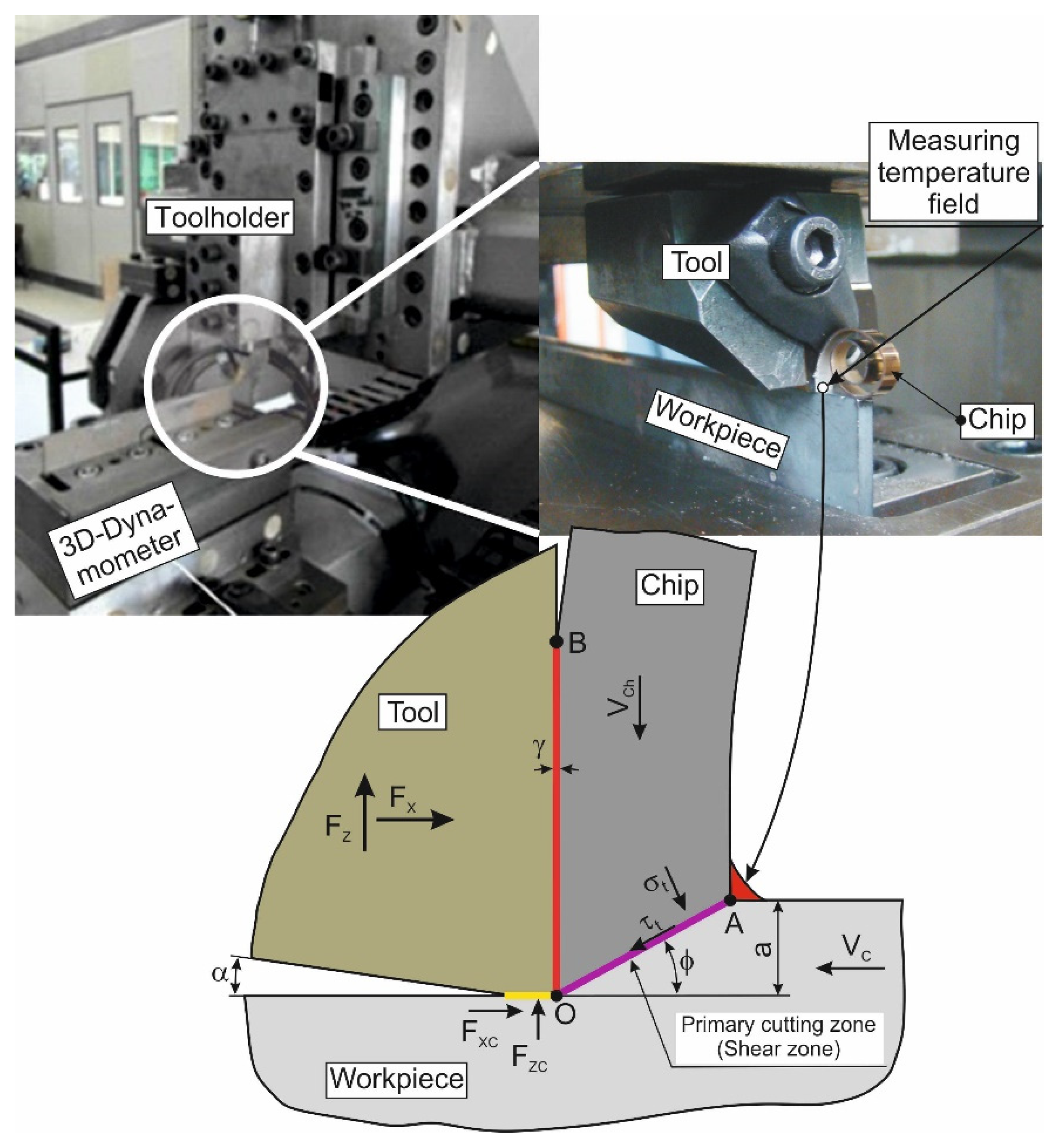
τ t = F X F X C cos ϕ ( F Z F Z C ) sin ϕ a w sin ϕ ,
where FX and FZ are the cutting force components measured in the orthogonal cutting process, FXC and FZC are the cutting and thrust forces at the clearance face of the tool wedge (in the tertiary cutting zone), respectively, ϕ is the shear angle, a is the depth of cut (or the undeformed chip thickness in the case of orthogonal cutting processes), and w is the cutting width.
The cutting temperature Tdmeas was measured during orthogonal cutting (see Section 3.1.1 and Section 4.1). The shear angle ϕ was determined using the chip compression ratio Ka and the tool orthogonal rake angle γ [92,93]:
ϕ = arctan 1 K a cos γ 1 1 K a sin γ ,
chip compression ratio
K a = a C a ,
where γ is the tool rake angle, and aC is the chip thickness.
In the case of adiabatic hardening of the machined material, the true final strain εw was established with the chip compression ratio Ka [92,93,94,95]:
ε w = K a + 1 K a 2 sin γ cos γ ,
The coefficient of heat flow from the primary cutting zone into the workpiece K was defined by the following equation [90,92]:
K P ε = 1 1 + 1 e P e tan ϕ P e tan ϕ = 1 1 + cot ϕ P e ,
where Pe is the Péclet number (Péclet criterion):
P e = V C a ω ,
where VC is the cutting speed, and ω is the coefficient of thermal diffusivity, defined as the quotient of the thermal conductivity coefficient and the coefficient of the specific volumetric heat capacity.
The following dependence was used to calculate the thermal conductivity coefficient λ [90,93,94]:
λ = ρ C m V C a tan ϕ 10 k 1 β k 2
where β is the proportion of heat flow into the workpiece (a similar quantity like the coefficient of heat flow from the primary cutting zone into the workpiece K), and k1 and k2 are the experimental coefficients.
A flowchart of the program algorithm for calculating the thermal properties of the machined material is shown in Figure 1.
The parameters of the constitutive equation and the friction model as well as the thermal properties of the machined material, determined in the way described above, were further used for the numerical modeling of the short hole drilling process.

3.1. Materials

AISI 1045, a well-known representative of thermo-treated structural steel, was chosen as material to be machined. Prior to experimental studies of both orthogonal cutting and short hole drilling, all used workpieces were subjected to tempering and a subsequent normalization to remove residual stresses generated in the workpiece subsurface layers during previous workpiece forming operations.

3.1.1. Orthogonal Cutting

The cutting temperature in the orthogonal cutting process and the thermal properties of the machined material were established with a special experimental stand [91,92]. A detailed specification of the experimental set-up for the realization of the orthogonal cutting process, measuring system, tool type, geometrical parameters of its cutting wedge, as well as cutting modes is given in the first part of the drilling process study devoted to the determination of kinetic characteristics [18]. When changing cutting modes (cutting speed and drill feed), new cutting inserts were used. In repeated tests with the same cutting modes, the cutting inserts were not changed. The drilling depth was set so that the wear of the cutting inserts was negligible. Since new inserts were used for each set of cutting modes, the influence of insert wear on the measurement results was negligible.
The cutting temperature was measured parallel to the cutting force components. The temperature was measured in the primary cutting zone from the outer surface of the formed chip at the transition region of the workpiece surface into the chip [72,90,96]. The experimental set-up for the temperature measurement is shown in Figure 2. The measurements were performed with a high-speed pyrometer, IGA-740 LO by LumoSense. The measuring field of the pyrometer was about 0.8 mm. The resolution time was 6 µsec. The pyrometer signal acquisition including its analog-to-digital conversion was carried out using a multifunction I/O device USB-6259 of National Instruments with a resolution of 16-bit and a data acquisition frequency of 1.25 MS/s. Subsequent processing of the pyrometer signal was carried out using the developed program in LabVIEW Professional Development System 2018. To perform the pyrometer calibration, the developed methodology [90] was applied by means of a special device using real chips obtained in the experiments studies at different cutting modes.
The process of orthogonal cutting was carried out without the use of coolant. To ensure the necessary reliability of the measured values, the tests for each set of cutting speeds were repeated at least 5 times. The specified minimum number of repetitions was used for both orthogonal cutting and drilling. The error bars were determined by the minimum and maximum values of the measured cutting temperatures. The confidence interval chosen was equal to 0.9. Since there were no significant differences between individual cutting temperature values, the average temperature value was used as a representative value. The largest error in temperature measurement by the pyrometer was 10%.

3.1.2. Short Hole Drilling

Experiments of the temperature distribution in the workpiece and the temperature change in the outer tool insert were carried out with the UWF 1202 H machining center by Hermle, depending on the cutting modes in the short hole drilling process. The experimental set-up for measuring the temperature distribution in the workpiece is shown in Figure 3. The drill was fixed in the machining center spindle using an HSK-32 shrink-chuck (see Figure 3d). The drill diameter was ∅ 25 mm. The short hole drilling tool was equipped with two square carbide inserts: an outer and an inner one (see Figure 3b). The outer and inner inserts were installed and fixed in the drill body so that the geometric parameters of the cutting wedge were the same. In this case, the rake angle was equal to γd = 0°. At the same time, the clearance angle of the cutting wedge was αd = 8°. The curvature radius of the cutting edge was 20 μm, and the curvature radius of the tips from the outer and inner plates was 4 mm. The plates were 5 mm thick. At a distance of 2 mm from the inserts’ cutting edges, a groove with a width of 1 mm was produced for swirling the chips [18]. The geometric parameters of the cutting inserts and the parameters of their fastening to the tool body were mainly consistent with the geometric parameters of the cutting inserts used in the orthogonal cutting process (see Section 3.1.1). The workpiece was fixed in a stationary four-jaw chuck on a Kistler four-component dynamometer, type 9272, which was mounted on the machining center table (see Figure 3a). The mantle thermocouple with transition sleeve, type K by tc-direct, was used to measure the temperature distribution in the workpiece. Such thermocouples have also been successfully used to measure the temperature in the tool during the drilling process [97]. The thermocouple diameter was 1 mm. Thermocouple signals, including their analog-to-digital conversion, were acquired via a CompactDAQ Chassis NI cDAQ-9178 with an embedded NI 9214 unit from National Instruments. The data acquisition frequency of the thermocouples was 70 S/s with 24-bit resolution. Signal processing was also performed via a program developed in the LabView 2018 environment. The measurement accuracy of the thermocouple signals was 0.1 °C. For the measurements, twelve thermocouples were used which were evenly arranged around the workpiece height and perimeter. The thermocouples were fixed to the workpiece using special adapters (see Figure 3a).
Figure 3b,c show the layout of the thermocouples on the circumference of the workpiece’s outer diameter and on the cylindrical surface of the workpiece. The temperature in the workpiece was measured at various distances from the cylindrical surface of the drilled hole. The distance between the drill hole wall and the temperature measuring point (thermocouple end) was 0.5 mm in row 0, 1.0 mm in row 1, 2.0 mm in row 2, and 3.0 mm in row 3 (Figure 3b). Before performing measurements, each thermocouple was calibrated within the region from room temperature to 300 °C. The thermocouples were calibrated using a block calibrator, type CTD 9100 by WIKA Alexander Wiegand SE & Co. KG, Klingenberg am Main, Germany.
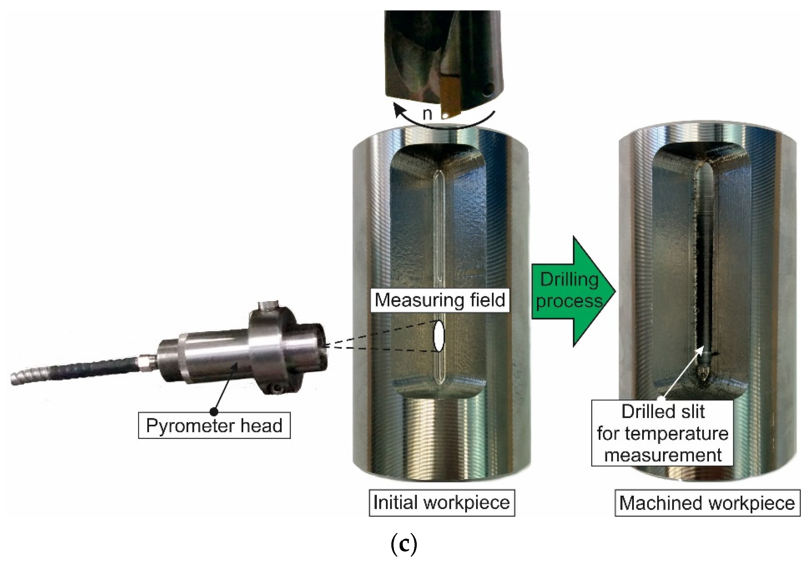
The test set-up for temperature measurement on the lateral clearance face of the drill outer cutting insert is shown in Figure 4. The temperature was measured using a high-speed pyrometer (see Section 3.1.1) that was fixed onto the machining center body—Figure 4a. The measurement area was the lateral clearance face of the outer insert, to which the pyrometer measurement field signal was directed (see Figure 4b). Figure 4c illustrates the scheme of the temperature measurement process at the specified location. A special workpiece shape with a pre-milled slit was used for the measurement (see the initial state of the workpiece in Figure 4c). During the drilling process, the workpiece slit was uncovered (see the final state of the drilled workpiece in Figure 4c). As soon as the lateral clearance face of the insert was visible through this opened slit during the drilling process, the corresponding temperature signal was recorded by the pyrometer [72].
The pyrometer signal acquisition and its processing were carried out by the same measuring system that was used to measure the temperature in the primary cutting zone from the outer surface of the formed chip at the transition region of the workpiece surface into the chip (see Section 3.1.1). The pyrometer was calibrated in the same way as in the study of the orthogonal cutting process according to the developed method [90] by means of a special device (see Section 3.1.1). The largest error in temperature measurement in this area was 11%.

3.2. Methods

The parameters of the model triad [53,64,65] had the main influence on the simulated characteristics of the cutting process. Therefore, it became essential to determine these parameters, ensuring that the simulated characteristic values of the cutting process were close enough to the corresponding experimental values. As in the first part of the numerical modeling study for short hole drilling [18], an orthogonal cutting model was used. The decisive argument in favor of using this process to determine the above-mentioned parameters was the simplicity and rapidity of such a numerical model.
The three-dimensional modeling of the orthogonal cutting process and the subsequent modeling of the short hole drilling process were developed in DEFORM V 12.0 2D/3D™ software environment [67]. A detailed description of the developed numerical cutting models is given in the first part of the drilling process study devoted to the determination of kinetic characteristics [18]. The measured cutting force and temperatures were used as target values when performing DOE sensitivity analyses. Local parameters of the contact interaction in the secondary and tertiary cutting zones were determined according to the procedure [98]. The values of local parameters were established with friction windows [64,98]. In the simulation process, an algorithm built into the software tool was used to divide the machined material into chip and machined workpiece volumes [67]. Therefore, it was not necessary to employ a special model of the machined material fracture [65,68].

3.2.1. Orthogonal Cutting Process

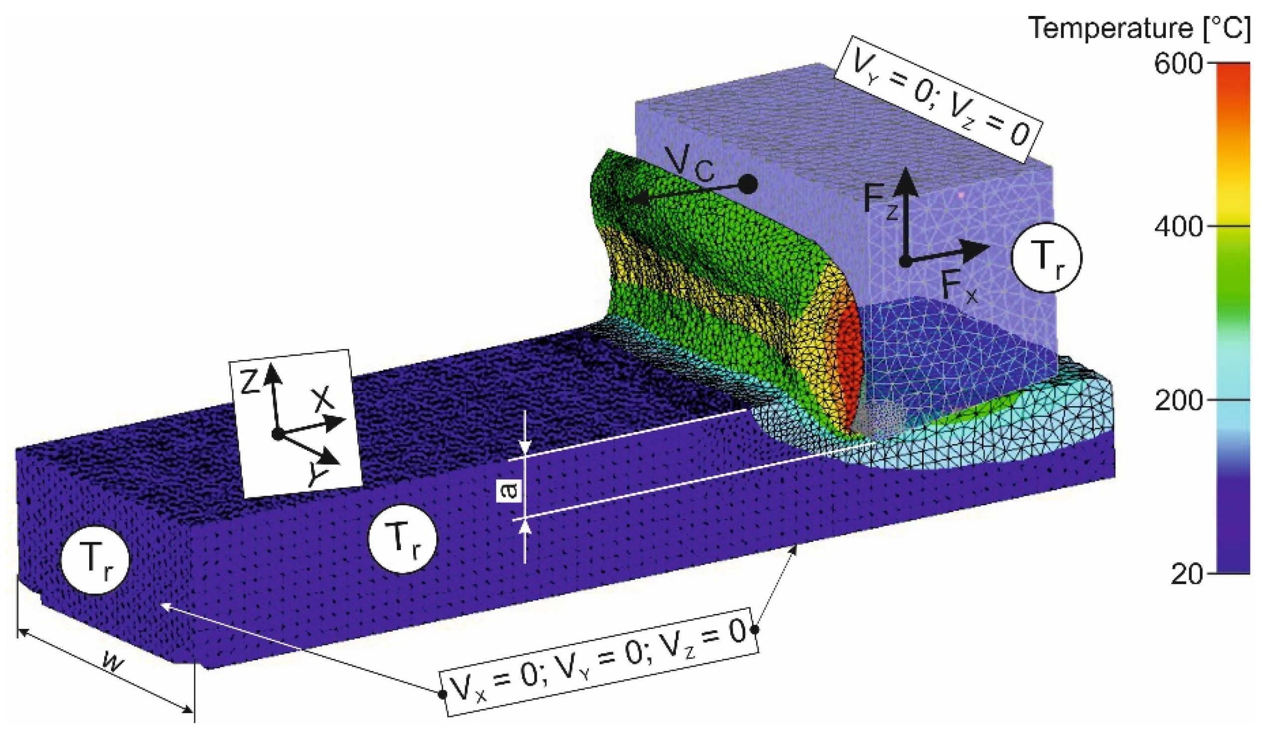
Figure 5 shows a 3D finite element model of the orthogonal cutting process combined with the results of the cutting temperature simulation. The boundary conditions were defined by rigidly clamping the bottom of the workpiece in all coordinate directions and rigidly clamping the tool onto the Z-axis and Y-axis. The initial thermal conditions Tr were set equal to room temperature. The relative movement of the tool and the workpiece was realized by an absolute translational movement of the tool in the negative direction of the X axis at cutting speed VC.
The initial finite element number of the workpiece was 56,324 elements and 12,232 nodes. The largest element side length of the workpiece model was about 0.098 mm. The smallest element side length of the workpiece model was about 0.032 mm. The initial number of tool finite elements was 27,438 elements and 6375 nodes. The largest element side length of the tool model was about 0.095 mm, and the smallest element side length of its smallest element was about 0.028 mm.

3.2.2. Short Hole Drilling

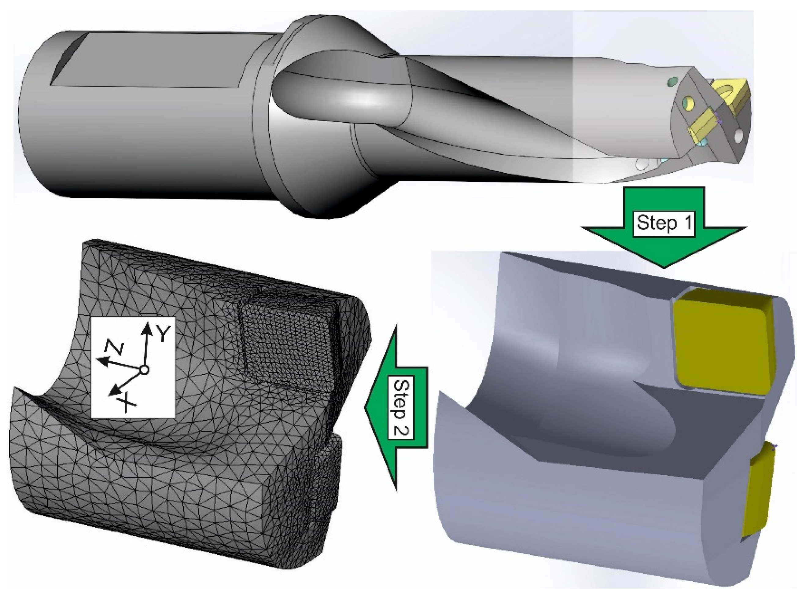
The heat flows in the workpiece and in the tool during the short hole drilling process were simulated using a 3D FEM model. The principal steps for building the tool geometric model are presented in Figure 6. The initial object of the geometric model was a CAD model of a drill equipped with replaceable carbide inserts. After the general analysis of the CAD model, its simplification was carried out. This was the first step of the procedure for building the geometric tool model. In the second step, the simplified drill model was partitioned into a mesh of finite elements (see Figure 6).
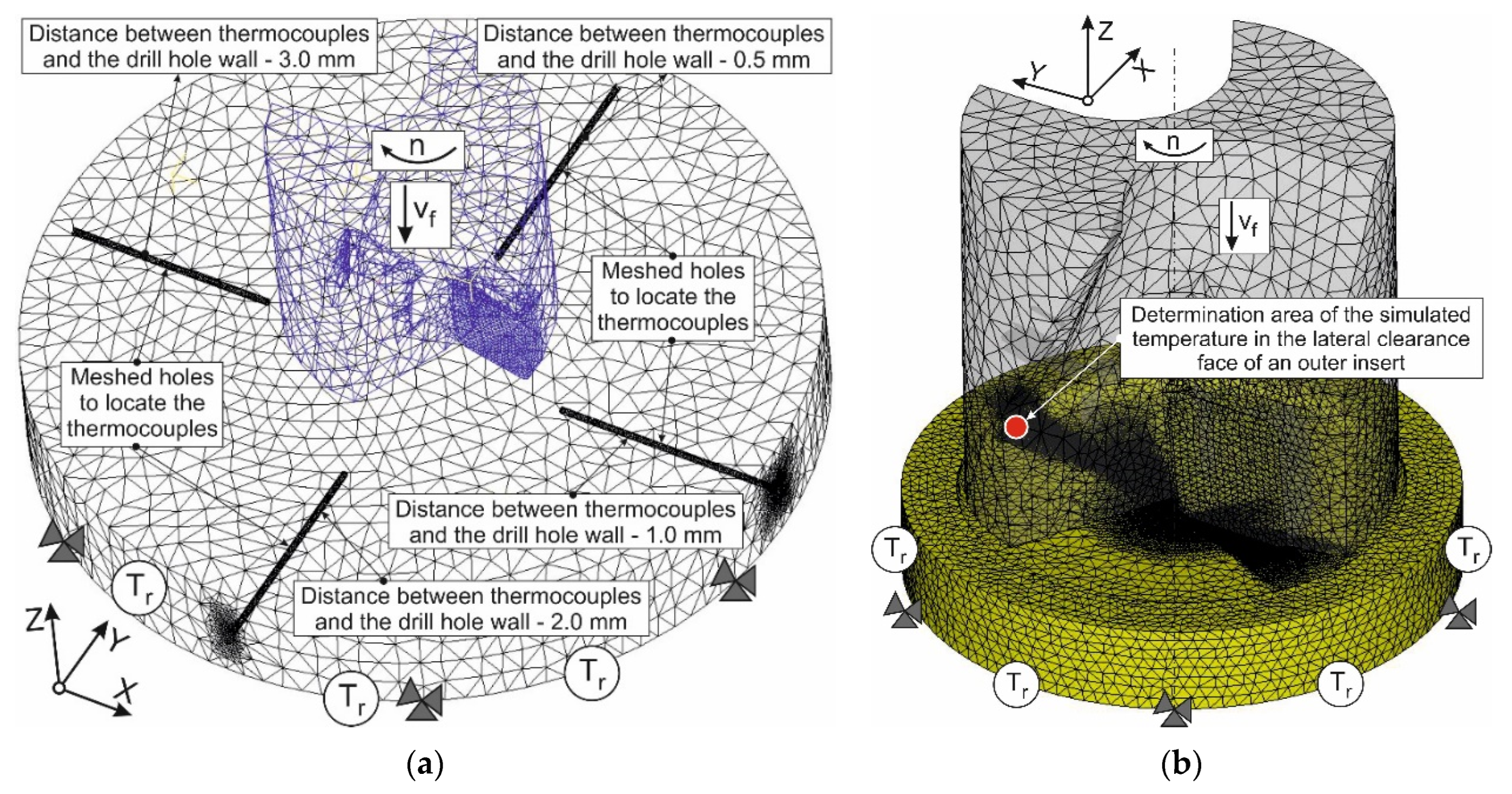
Figure 7 shows the mesh and boundary conditions of the initial geometric models for the short hole drilling process to simulate both the temperature distribution in the workpiece and the temperature simulation in the outer carbide insert. The workpiece movements in the developed model were constrained along all coordinate axes. The tool was given a rotary motion with a revolution frequency n and a translational motion in the negative direction of the Z-axis at a feed rate vf (see Figure 7).
The initial thermal conditions Tr were specified along the tool and workpiece boundaries. A significantly finer mesh was used in the expected areas of the cutting zones than in the rest of the tool and the workpiece. The initial finite element number of the workpiece was 127,637 elements and 28,267 nodes. The largest element side length of the workpiece model was about 0.789 mm. The smallest element side length of the workpiece model was about 0.0823 mm. The initial number of the drill body finite elements was 36,947 elements and 8325 nodes. The largest element side length of the tool model was about 1.393 mm, and the smallest element side length of its smallest element was about 0.334 mm. The initial number of the inserts finite elements was 23,425 elements and 6515 nodes. The largest element side length of the inserts model was about 0.734 mm, and the smallest element side length of its smallest element was about 0.0842 mm.
To simulate the temperature during the drilling process at different workpiece points, four radial cylindrical holes were included in the geometric model from the periphery of the workpiece to its center (see Figure 7a). These holes simulated the position of thermocouples used in the experiments for measuring the temperature of the workpiece at various distances from the wall of the drilled hole. The simulated temperatures were determined at the end of the above-mentioned cylindrical holes. The geometric model shown in Figure 7b was used to simulate the temperature during the drilling process in the carbide inserts. The location of the specified temperature (see Figure 7b) corresponded to the location of its measurement (see Section 3.1.2).

4. Results and Discussion

The measured and simulated kinetic and thermal characteristics of the orthogonal cutting process were used to determine the parameters of the triad component models (see Section 3.2). The parameters of these models were subsequently applied in a finite element model of short hole drilling. The validity and reliability of the numerical model of drilling were evaluated by comparing the experimental and simulated values of the cutting temperature at different workpiece points as well as on the lateral clearance face of the outer cutting insert.

4.1. Orthogonal Cutting Process

The results of the cutting force components FX and FZ in the orthogonal cutting process, measured earlier and presented in the first part of the numerical modeling study of the short hole drilling process [18], were used to determine the constitutive equation parameters of the machined material and friction model parameters. The above-mentioned parameters are presented in Table 1. By studying the orthogonal cutting process, it was possible to find out the thermal properties of the machined material which are required to simulate the thermal flow of the workpiece and the cutting temperature in the tool during the short hole drilling process. For this purpose, the chip compression ratio and the temperature were measured on the outside of the chip in the transition region from the machined material to the chip (see Figure 2). These data were necessary to determine the thermal properties of the machined material, according to our previously developed methodology [90] (see also Section 3).
The effect of cutting speed on the chip compression ratio and cutting temperature in the primary cutting zone is shown in Figure 8. The change in chip compression ratio with increasing cutting speed (see Figure 8a) corresponds to a kind of S-shaped form.
In the region of low cutting speeds, there was a significant decrease in chip compression ratio, which then grew slightly as the cutting speed increased to the commonly used values. When the cutting speed was further increased to significant values, the chip compression ratio also decreased monotonically. The presence of the S-shaped dependence could be explained by the fact, widely known in cutting theory, that a built-up occurs on the tool rake face at relatively low cutting speeds and its subsequent damage with increasing cutting speed [93,94]. A significant reduction in chip compression ratio in the region of conventional and high cutting speeds was related to a significant increase in the cutting temperature, providing the prevailing effect of machined material softening over the hardening effect of its plastic deformation [92,95]. The temperature in the primary cutting zone increased monotonically with increasing cutting speed (see Figure 8b).
The measured chip compression ratio and temperature values in the primary cutting zone, shown in Figure 8, were used to determine the mass-specific heat capacity Cm and the thermal conductivity coefficient λ separately for different cutting speeds, corresponding to the average cutting speeds of the outer and inner tool inserts during short hole drilling. The specified thermal properties of the machined material were established with the methodology previously developed by us [90] and summarized in Section 3. Based on the thermal properties of the machined material determined separately for different cutting speeds, the generalized values of Cm and λ were established, which were subsequently used to simulate the thermal characteristics of the short hole drilling process. The generalized values of these parameters were established using the previously developed algorithm for finding the intersection of parameter sets [89] through multiple iterations of DOE (design of experiment) sensitivity analyses [67]. To perform a DOE sensitivity analysis, the measured temperature values in the primary cutting zone were used as target values. The thermal property values of the machined material determined in this way are given in Table 2.

4.2. Short Hole Drilling

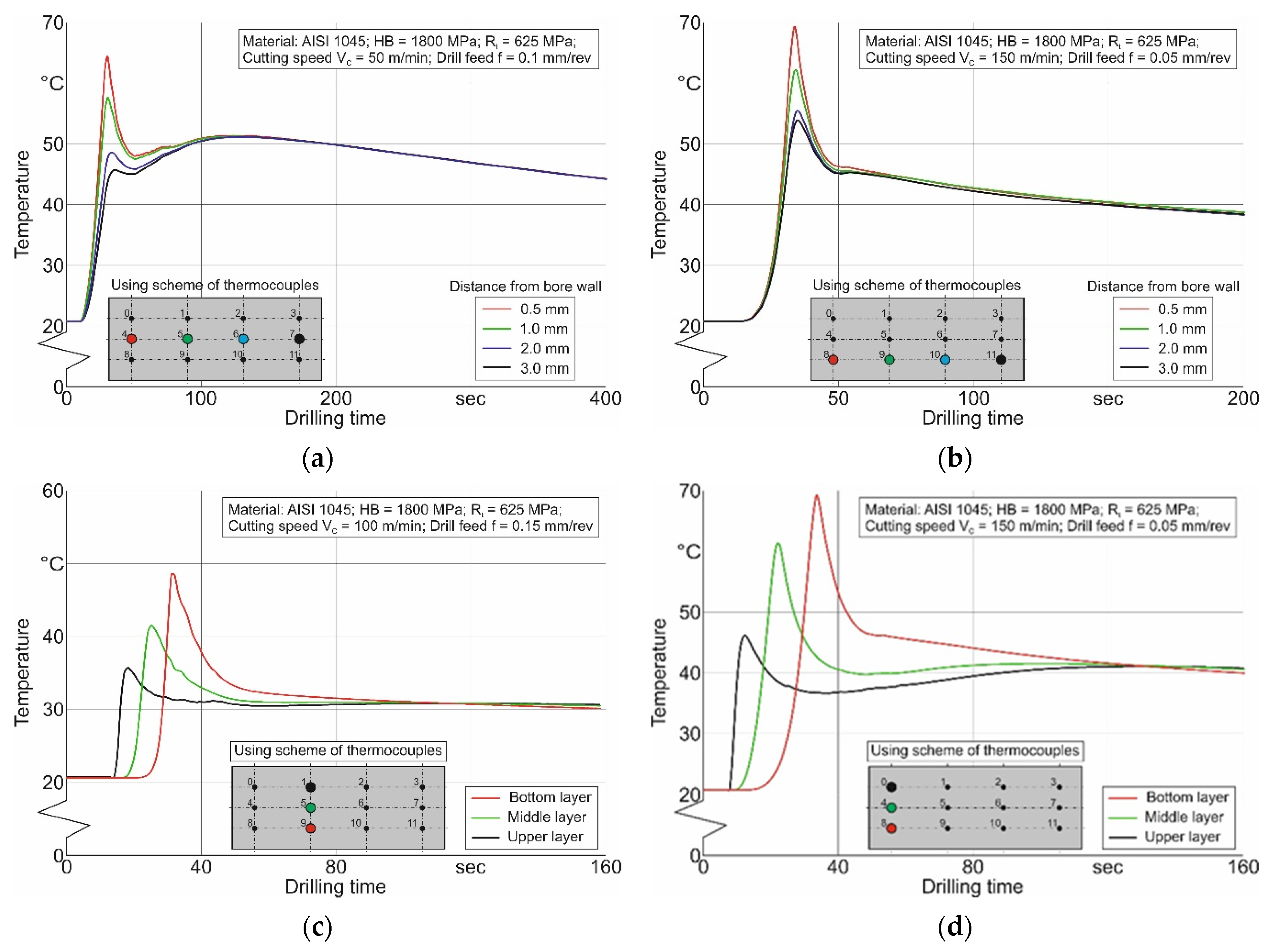
The experiments of cutting temperatures in the short hole drilling process were carried out in two ways: measuring the temperature distributions in the workpiece and determining the temperature in the drill cutting inserts in the contact area with the machined material during cutting. Figure 9 shows an example of the temperature distribution in the workpiece for different layers of thermocouples and at different distances from the drill hole surface. As the tool penetrated deeper into the drilled hole, the temperature in the workpiece increased. The temperature on the workpiece points at the middle layer was slightly lower, by approximately 6 °C to 10 °C, than the temperature on the corresponding points at the lower layer (see Figure 9a,b). The highest values of workpiece temperature were observed at points closer to the surface of the drill hole. Thus, the temperature on workpiece points located at a distance of 1 mm from the drilled hole was about 10 °C to 18 °C lower than the temperatures on points located at a distance of 0.5 mm from the surface of the drilled hole. This was quite natural and needed no special explanation.
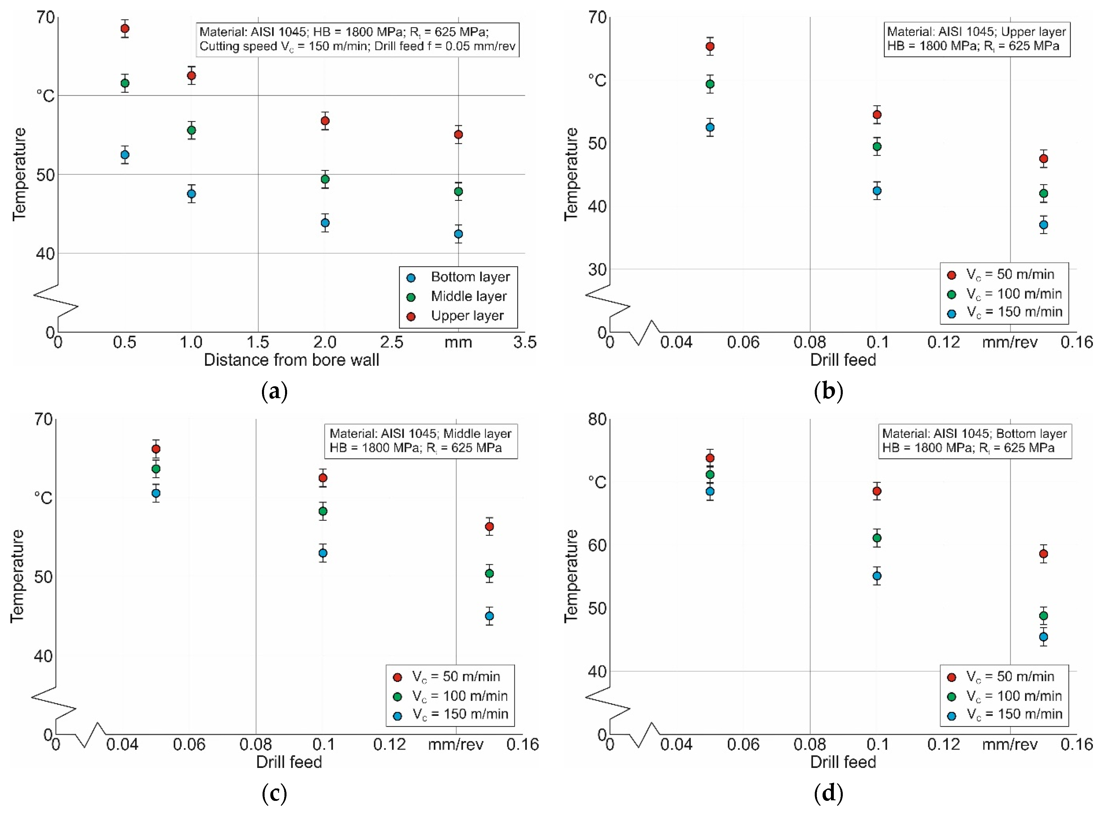
Figure 10 presents a summarized view of the temperature distribution in the workpiece during short hole drilling, depending on the temperature measuring point and on the cutting modes. The temperature in the workpiece decreased quite significantly with growing distance from the heat source, which is the cutting zone (see Figure 10a). As the tool feed increased, the temperature on various points at the workpiece decreased as well (see Figure 10b–d). Moreover, the nature of this decrease also changed. The temperature reduction with increasing drill feed was due to the decreasing time that the heat source lingered at the temperature measuring point with increasing tool feed. In all probability, the decrease in this time prevailed over the increase in the intensity of the cutting process with increasing feed. As a result, the workpiece temperature at the measuring points decreased. As the cutting speed increased, the temperature decreased as well (see Figure 10b–d). The cutting speed also contributed to the decrease in workpiece temperature by reducing the time the heat source lingered near the temperature measuring point.
Figure 11a shows the signal registered with a pyrometer. This signal corresponded to the temperature on the lateral clearance face of the outer cutting insert (see Section 3.1.2, Figure 4). Figure 11b summarizes and presents the temperature variation at the indicated point as a function of cutting modes. The cutting temperature, measured on the specified point of contact between the cutting insert and the machined material during the drilling process, increased slightly with increasing tool feed. This was due to an increase in the volume of material removed per unit time, i.e., an increase in the intensity of the cutting process. The cutting temperature increased quite significantly with increasing cutting speed. This corresponded to the nature of the cutting speed influence, which is widely known from the cutting theory [93,94].
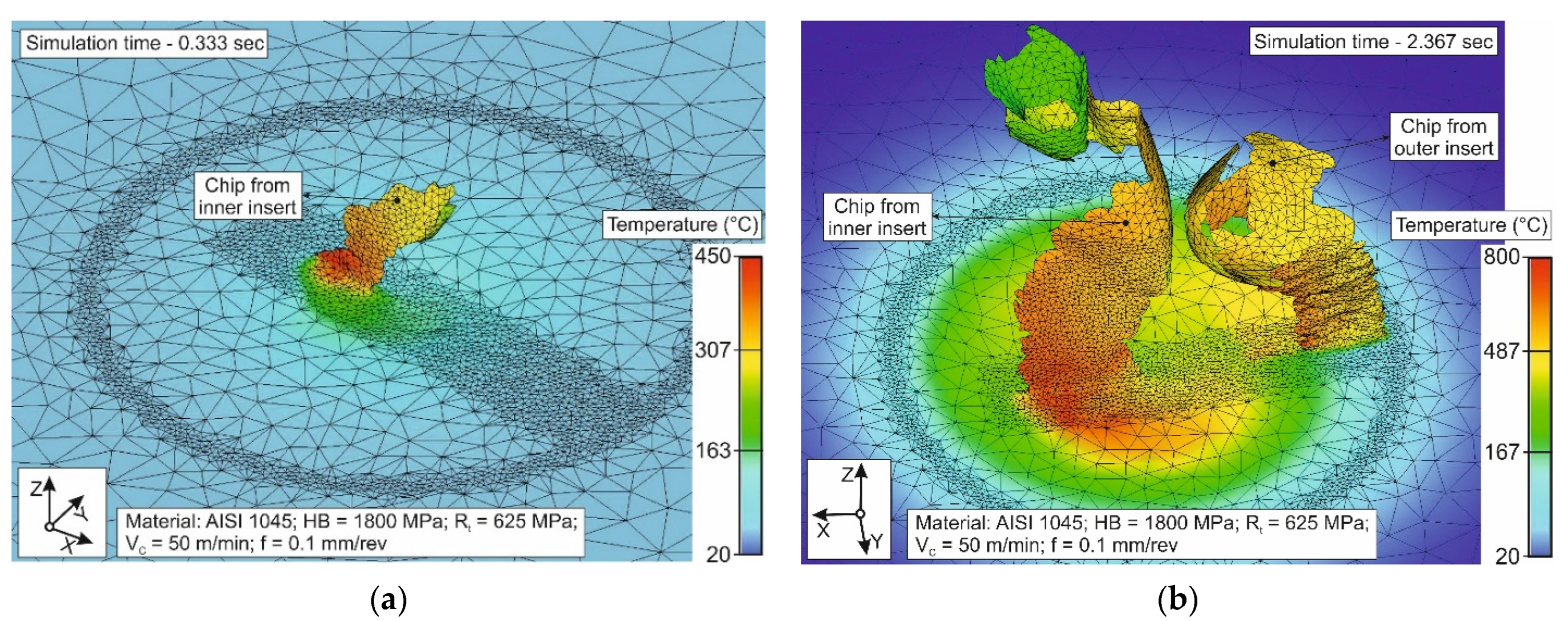
The initial validation of the developed numerical model for the short hole drilling process consisted of checking the convergence of the numerical algorithm, its functioning, and the visual validity of the obtained results. This was performed by analyzing the chip-forming process and evaluating the numerical simulation results of the thermal cutting characteristics. Figure 12 presents the simulation results of the chip-forming process and the development of thermal characteristics in the machined workpiece at a cutting speed of VC = 100 m/min and a drill feed equal to 0.1 mm/rev. The initial stage of drill penetration into the workpiece, recorded at a machining time of 0.333 s from the machining start, is shown in Figure 12a. In this step, the chip-forming process was carried out by an inner cutting insert positioned somewhat below the outer insert. The chip temperature did not exceed 450 °C. At the steady state cutting phase fixed at a machining time of 2.367 s after the drill entry into the workpiece, the chip formation was already ensured by two cutting inserts. In this case, the maximum chip temperature corresponded to a level of about 800 °C. The simulated chip-forming process corresponded visually quite well to the real process of chip formation by the inner and outer cutting inserts of the drill. The development of thermal loads as the drill penetrated the workpiece was not contrary to the known data.
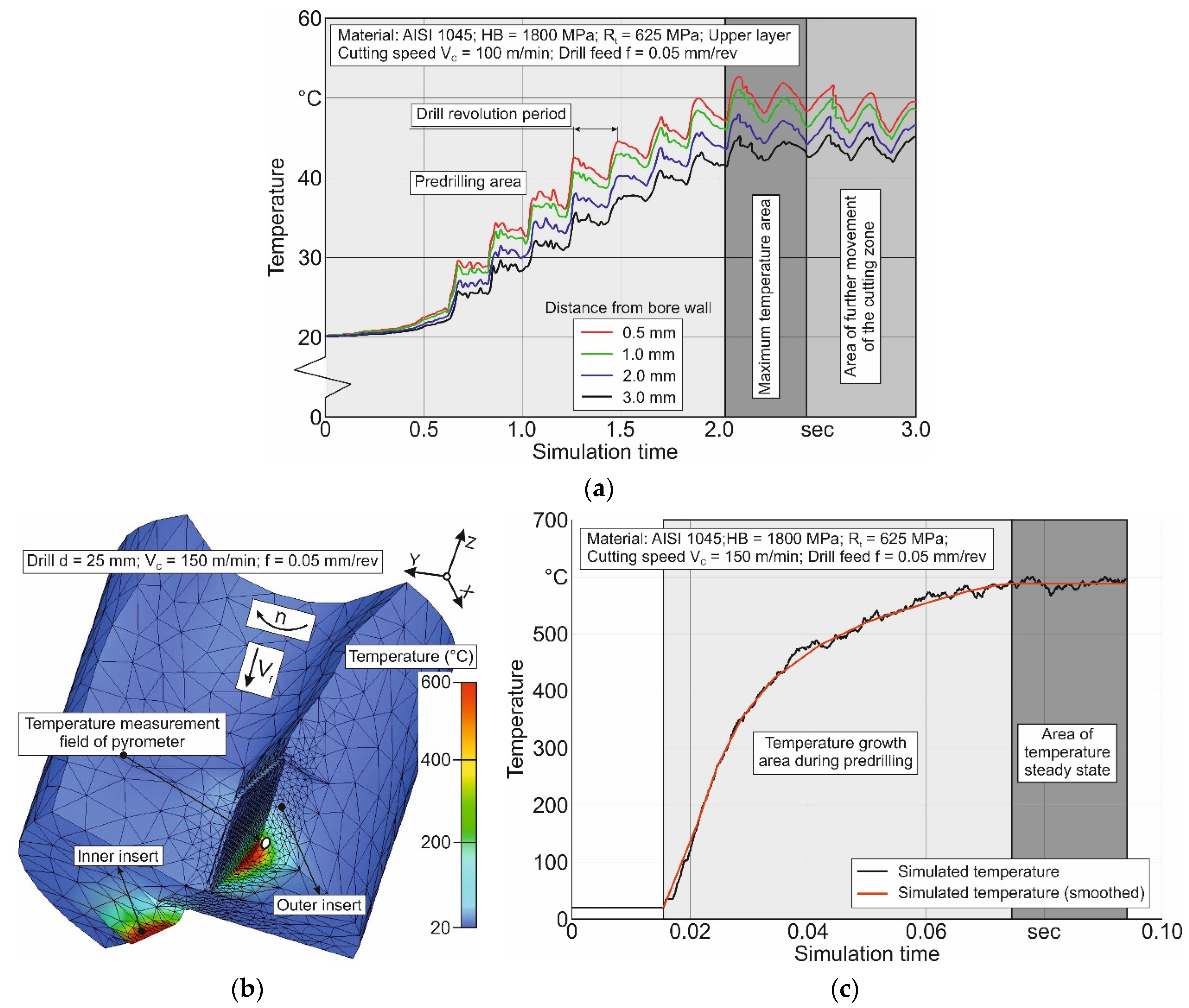
The next validation stage of the developed finite element model for drilling short holes was to take account of and analyze the results of simulating the changing thermal characteristics in the workpiece and on the lateral clearance face of the outer drill insert. These results are summarized in Figure 13. The temperature at the upper workpiece layer, measured at the ends of the thermocouples located at different distances from the drill hole surface, rose to a maximum value and then decreased (see Figure 13a).
The maximum temperature value recorded by the thermocouples corresponded to the moment when the cutting zones were located near the measuring point. The temperature values corresponding to these moments were recorded during experiments (see Figure 9 and Figure 10). The simulated temperature distribution in the tool is shown in Figure 13b. The greatest thermal load was on the cutting edges of the drill inserts and the areas adjacent to them. The simulated temperature on the lateral clearance face of the outer cutting insert in the vicinity of the field corresponding to the pyrometer measuring field (see Figure 4c and Figure 11) increased monotonically and reached a steady state after about 0.07 s simulation time—Figure 13c. This temperature value was taken as the temperature in the specified area of contact between the outer cutting insert and the machined material. The results presented above indicate the functioning of the developed numerical model for short hole drilling, its ability to simulate the thermal characteristics of the machining process, the visual validity of these results, as well as the counting algorithm itself, providing sufficient convergence.
The final verification of whether it is possible to adequately simulate the thermal characteristics of the drilling process with the analyzed finite element model was tested by comparing the measured cutting temperature with the corresponding simulated values. The above-presented and analyzed experimental results of the temperature distribution at different points of the workpiece as well as the results of the temperature measurements on the lateral clearance face of the outer drill insert were then used to compare these values with the corresponding simulated values.
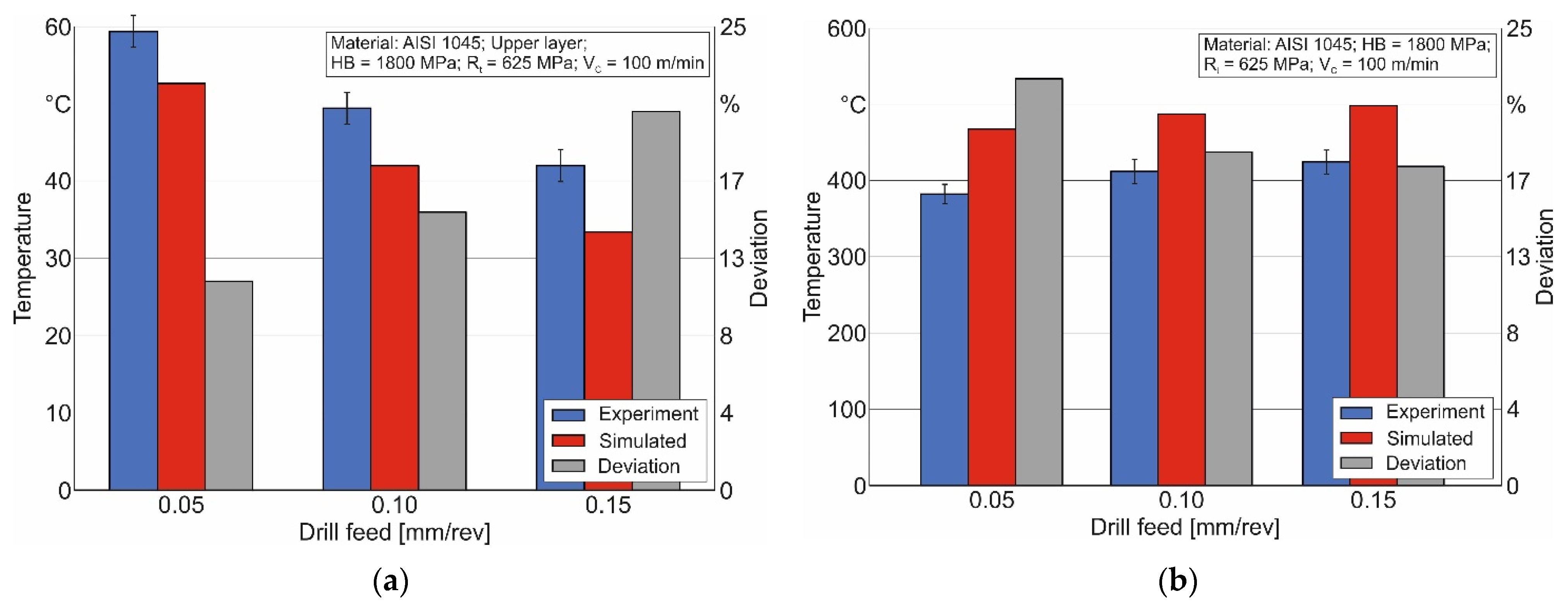
As an example, Figure 14 shows a comparison of the measured and simulated temperature distributions in the workpiece and on the lateral clearance face of the outer drill insert for a cutting speed of VC = 100 m/min. The greatest deviation in the simulated temperature values in the workpiece from the corresponding measured values was observed at the highest drill feed and was equal to 20.4%—Figure 14a. In this case, the simulated temperature values were lower than the measured values for the whole range of applied tool feeds. In all probability, the observed deviation was caused by an imperfect consideration of all the peculiarities regarding the thermomechanical loading of the machined material during the cutting process in the constitutive equation, friction model, as well as in the thermal properties used. Moreover, the simulated temperature values in the examined field of the lateral clearance face on the outer drill insert were higher than the corresponding measured values for the whole range of drill feed variation. In this case, the greatest deviation between simulated and measured temperature values was observed at the lowest tool feed and was equal to 22.4%. The causes of these deviations should, in all likelihood, be attributed to the reasons mentioned above. In addition, inaccuracies in the thermal properties of the cutting material should be pointed out as a cause.
Nevertheless, the above-mentioned deviations were no obstacle to using the developed numerical model for short hole drilling to simulate the thermal characteristics of the drilling process, since the greatest deviations of the measured temperature values from their simulated values did not exceed 22.4%.

5. Conclusions

The thermal characteristics modeling of the short hole drilling process with a numerical model was the focus of the presented study. The thermal material properties, the constitutive equation parameters, as well as the friction model parameters were determined using a 3D finite element model of orthogonal cutting. The thermal properties of the machined material were determined separately for the different contact conditions of the drill inserts. The algorithm previously developed by us for finding the intersection of specific value sets of these properties was used to determine the generalized values of the thermal material properties. The algorithm was executed through a DOE sensitivity analysis. The measured temperature values in the primary cutting zone at the exterior side of the chip near transition area from the machined material to the chip were used as goal data for the DOE sensitivity analysis.
The final adequacy check of the developed finite element model for thermal characteristics simulation in the short hole drilling process was performed by comparing the measured and simulated temperature values at different points of the workpiece and on the lateral clearance face of the outer drill insert. The greatest deviation between measured and simulated temperature values in the workpiece was 20.4% at the highest drill feed of 0.15 mm/rev. The largest discrepancy between simulated and measured temperature values on the lateral clearance face of the outer drill insert was 22.4% at the lowest drill feed of 0.05 mm/rev.
Based on the fixed deviations of the simulated values from the temperatures of the corresponding measured values, it can be asserted that the developed numerical model can be used to satisfactory modeling the thermal characteristics during the short hole drilling process. This will reduce the time and cost of experimental studies into the mentioned machining process.

Author Contributions

Conceptualization, M.S.; methodology, M.S.; software, M.S.; validation, M.S.; formal analysis, M.S.; investigation, M.S.; resources, T.S. and H.-C.M.; data curation, M.S.; writing—original draft preparation, M.S.; writing—review and editing, M.S.; visualization, M.S.; project administration, H.-C.M. and T.S.; funding acquisition, H.-C.M. and T.S. All authors have read and agreed to the published version of the manuscript.

Funding

This study was funded by the German Research Foundation (DFG) in the project HE 1656/146 “Modeling and compensation of thermal machining influences for short hole drilling”.

Data Availability Statement

Data are contained within the article.

Acknowledgments

The authors would like to thank the German Research Foundation (DFG) for their support, which is highly appreciated.

Conflicts of Interest

The authors declare no conflicts of interest. The funders had no role in the design of the study; in the collection, analyses, or interpretation of data; in the writing of the manuscript; or in the decision to publish the results.

References

  1. van Luttervelt, C.; Childs, T.; Jawahir, I.; Klocke, F.; Venuvinod, P.; Altintas, Y.; Armarego, E.; Dornfeld, D.; Grabec, I.; Leopold, J.; et al. Present Situation and Future Trends in Modelling of Machining Operations Progress Report of the CIRP Working Group ‘Modelling of Machining Operations’. CIRP Ann. 1998, 47, 587–626. [Google Scholar] [CrossRef]
  2. Arrazola, P.; Özel, T.; Umbrello, D.; Davies, M.; Jawahir, I. Recent advances in modelling of metal machining processes. CIRP Ann. Manuf. Technol. 2013, 62, 695–718. [Google Scholar] [CrossRef]
  3. Mourtzis, D.; Doukas, M.; Bernidaki, D. Simulation in Manufacturing: Review and Challenges. Procedia CIRP 2014, 25, 213–229. [Google Scholar] [CrossRef]
  4. Melkote, S.; Liang, S.Y.; Ozel, T.; Jawahir, I.S.; Stephenson, D.A.; Wang, B. A Review of Advances in Modeling of Conventional Machining Processes: From Merchant to the Present. ASME J. Manuf. Sci. Eng. 2022, 144, 110801. [Google Scholar] [CrossRef]
  5. Ulutan, D.; Lazoglu, I.; Dinc, C. Three-dimensional temperature predictions in machining processes using finite difference method. J. Am. Acad. Dermatol. 2009, 209, 1111–1121. [Google Scholar] [CrossRef]
  6. Davim, J.P. Drilling Technology: Fundamentals and Recent Advances; De Gruyter Oldenbourg: Boston, MA, USA, 2018; 205p, ISBN 978-3110478631. [Google Scholar]
  7. Isbilir, O.; Ghassemieh, E. Finite Element Analysis of Drilling of Titanium Alloy. Procedia Eng. 2011, 10, 1877–1882. [Google Scholar] [CrossRef]
  8. Babichev, D.; Storchak, M. Synthesis of cylindrical gears with optimum rolling fatigue strength. Prod. Eng. 2015, 9, 87–97. [Google Scholar] [CrossRef]
  9. Davim, J.P. Machining of Complex Sculptured Surfaces; Springer: London, UK, 2012; 258p. [Google Scholar] [CrossRef]
  10. Patel, P.; Intwala, A.; Patel, D.; Gandhi, D.; Patel, N.; Patel, M. A Review Article on Effect of Cutting Parameter on Drilling Operation for Perpendicularity. J. Mech. Civ. Eng. 2014, 11, 11–18. [Google Scholar] [CrossRef]
  11. Risse, K. Einflüsse von Werkzeugdurchmesser und Schneidkantenverrundung beim Bohren mit Wendelbohrern in Stahl. Ph.D. Dissertation, Rheinisch-Westfälischen Technischen Hochschule Aachen, Aachen, Germany, 2006; 137p. ISBN: 978-3-8322-5252-6. Available online: http://publications.rwth-aachen.de/record/61346/files/Risse_Kai.pdf (accessed on 24 May 2023).
  12. Andersson, T.; Svensson, D.; Lassila, A.A. 3D-Simulation of Heat Flow in Indexable Drilling. Key Eng. Mater. 2023, 955, 53–62. [Google Scholar] [CrossRef]
  13. Okada, M.; Asakawa, N.; Sentoku, E.; M’saoubi, R.; Ueda, T. Cutting performance of an indexable insert drill for difficult-to-cut materials under supplied oil mist. Int. J. Adv. Manuf. Technol. 2014, 72, 475–485. [Google Scholar] [CrossRef]
  14. Jiang, A.; Liu, Z.; Wang, S.; Wen, J.; Li, Y.; Zhao, J. Optimized design of indexable insert drill based on radial cutting force balance. Int. J. Adv. Manuf. Technol. 2023, 128, 2029–2041. [Google Scholar] [CrossRef]
  15. Usui, E.; Shirakashi, T. Mechanics of Metal Cutting–From “Description” to “Predictive” Theory’, on the Art of Cutting Metals–75 Years Later; Production Engineering Division (PED): Phoenix, AZ, USA; ASME: New York, NY, USA, 1982; Volume 7, pp. 13–25. [Google Scholar]
  16. Ma, L.; Marusich, T.D.; Usui, S.; Wadell, J.; Marusich, K.; Zamorano, L.; Elangovan, H. Validation of Finite Element Modeling of Drilling Processes with Solid Tooling in Metals. Adv. Mater. Res. 2011, 223, 182–190. [Google Scholar] [CrossRef]
  17. Rowe, W.; Jin, T. Temperatures in High Efficiency Deep Grinding (HEDG). CIRP Ann. 2001, 50, 205–208. [Google Scholar] [CrossRef]
  18. Storchak, M.; Stehle, T.; Möhring, H.-C. Numerical Modeling of Cutting Characteristics during Short Hole Drilling: Modeling of Kinetic Characteristics. J. Manuf. Mater. Process. 2023, 7, 195. [Google Scholar] [CrossRef]
  19. Komanduri, R. Machining and Grinding: A Historical Review of the Classical Papers. Appl. Mech. Rev. 1993, 46, 80–132. [Google Scholar] [CrossRef]
  20. Tiffe, M.; Biermann, D. Modelling of Tool Engagement and FEM-Simulation of Chip Formation for Drilling Processes. Adv. Mater. Res. 2014, 1018, 183–188. [Google Scholar] [CrossRef]
  21. Yang, Y.; Sun, J. Finite Element Modelling and Simulating of Drilling of Titanium Alloy. In Proceedings of the Second International Conference on Information and Computing Science, Manchester, UK, 21–22 May 2009; pp. 178–181. [Google Scholar] [CrossRef]
  22. Klocke, F.; Abouridouane, M.; Gerschwiler, K.; Lung, D. 3D Modelling and Simulation of Gun Drilling. Adv. Mater. Res. 2011, 223, 12–19. [Google Scholar] [CrossRef]
  23. Gyliene, V.; Ostasevicius, V.; Ubartas, M. Drilling Process using SPH. In Proceedings of the 9th European LS-Dyna Conference, Manchester, UK, 2–4 June 2013; 6p. Available online: https://www.google.de/url?sa=t&rct=j&q=&esrc=s&source=web&cd=&cad=rja&uact=8&ved=2ahUKEwjm4KGViKiDAxXThv0HHXH1BXIQFnoECBIQAQ&url=https%3A%2F%2Fwww.dynalook.com%2Fconferences%2F9th-european-ls-dyna-conference%2Fdrilling-process-modelling-using-sph&usg=AOvVaw2eXV705TLft3Dt5R-C1HW0&opi=89978449 (accessed on 2 June 2023).
  24. Tajdari, M.; Tai, B.L. Modeling of Brittle and Ductile Materials Drilling Using Smoothed-Particle Hydrodynamics. In Proceedings of the ASME 2016 11th International Manufacturing Science and Engineering Conference, Blacksburg, WV, USA, 27 June–1 July 2016. 7p. [Google Scholar] [CrossRef]
  25. Türkes, E.; Erdem, M.; Gok, K.; Gok, A. Development of a new model for determine of cutting parameters in metal drilling processes. J. Braz. Soc. Mech. Sci. Eng. 2020, 42, 169. [Google Scholar] [CrossRef]
  26. Marusich, T.D.; Usui, S.; Stephenson, D. A Finite element modeling of drilling processes with solid and indexable tooling in metals and stack-ups. In Proceedings of the Procedia 10th CIRP, International Workshop on Modeling of Machining Operations, Reggio Calabria, Italy, 27–28 August 2007; pp. 51–58. Available online: https://www.google.de/url?sa=t&rct=j&q=&esrc=s&source=web&cd=&cad=rja&uact=8&ved=2ahUKEwjppZKEiaiDAxV3gv0HHXq9C28QFnoECBYQAQ&url=https%3A%2F%2Fthirdwavesys.com%2Fwp-content%2Fuploads%2F2019%2F10%2FFEM_Drilling_SolidIndexable_Metals_StackUps.pdf&usg=AOvVaw3PAzfcHjeHNL_blyKuJXL2&opi=89978449 (accessed on 27 August 2023).
  27. Anbarasan, M.; Senthilkumar, N.; Tamizharasan, T. Modelling and Simulation of Conventional Drilling Process using Deform 3D. Int. J. Mech. Dyn. Anal. 2019, 5, 9–16. Available online: https://www.google.de/url?sa=t&rct=j&q=&esrc=s&source=web&cd=&cad=rja&uact=8&ved=2ahUKEwj0g6q4iaiDAxVE_bsIHfehB18QFnoECBEQAQ&url=https%3A%2F%2Fmechanical.journalspub.info%2Findex.php%3Fjournal%3DJMDA%26page%3Darticle%26op%3Dview%26path%255B%255D%3D990&usg=AOvVaw3j3vCYRsU-KSQ5U9KV-S2B&opi=89978449 (accessed on 15 March 2023).
  28. Gardner, J.D.; Dornfeld, D. Finite Element Modeling of Drilling Using DEFORM; UC Berkeley: Laboratory for Manufacturing and Sustainability: Berkeley, CA, USA, 2006; 8p, Available online: https://escholarship.org/uc/item/9xg0g32g (accessed on 1 June 2023).
  29. Boldyrev, I.S.; Topolov, D.Y. Twist Drilling FEM Simulation for Thrust Force and Torque Prediction. In Proceedings of the 6th International Conference on Industrial Engineering (ICIE 2020), Lecture Notes in Mechanical Engineering, Sochi, Russia, 18–22 May 2020; Radionov, A.A., Gasiyarov, V.R., Eds.; pp. 946–952. [Google Scholar] [CrossRef]
  30. Ucun, I. 3D finite element modelling of drilling process of Al7075-T6 alloy and experimental validation. J. Mech. Sci. Technol. 2016, 30, 1843–1850. [Google Scholar] [CrossRef]
  31. Parida, A.K. Simulation and experimental investigation of drilling of Ti-6Al-4V alloy. Int. J. Light. Mater. Manuf. 2018, 1, 197–205. [Google Scholar] [CrossRef]
  32. Girinon, M.; Valiorgue, F.; Karaouni, H.; Feulvarch, É. 3D numerical simulation of drilling residual stresses. Comptes Rendus Mec. 2018, 346, 701–711. [Google Scholar] [CrossRef]
  33. Kheireddine, A.; Ammouri, A.; Lu, T.; Jawahir, I.; Hamade, R. An FEM Analysis with Experimental Validation to Study the Hardness of In-Process Cryogenically Cooled Drilled Holes in Mg AZ31b. Procedia CIRP 2013, 8, 588–593. [Google Scholar] [CrossRef]
  34. Fandiño, D.; Guski, V.; Wegert, R.; Schmauder, S.; Möhring, H.-C. Numerical Investigations on Single Lip Deep Hole Drilling. Procedia CIRP 2021, 102, 132–137. [Google Scholar] [CrossRef]
  35. Nagaraj, M.; Ezilarasan, C.; John Presin Kumar, A.; Velayudham, A. A Review of Machining Characteristics in Mechanical Drilling of Super Alloys. Int. J. Mech. Prod. Eng. Res. Dev. 2018, 8, 579–588. Available online: https://www.tjprc.org/publishpapers/2-67-1538806991-64.IJMPERDFEB201864.pdf (accessed on 28 February 2023).
  36. Oezkaya, E.; Michel, S.; Biermann, D. Experimental and computational analysis of the coolant distribution considering the viscosity of the cutting fluid during machining with helical deep hole drills. Adv. Manuf. 2022, 10, 235–249. [Google Scholar] [CrossRef]
  37. Oezkaya, E.; Michel, S.; Biermann, D. Chip formation simulation and analysis of the mechanical loads during micro single-lip deep hole drilling of Inconel 718 with varying cooling lubricant pressure. Prod. Eng. 2021, 15, 299–309. [Google Scholar] [CrossRef]
  38. Abouridouane, M.; Klocke, F.; Lung, D.; Adams, O. A new 3D multiphase FE model for micro cutting ferritic–pearlitic carbon steels. CIRP Ann. 2012, 61, 71–74. [Google Scholar] [CrossRef]
  39. Kumar, A.; Bhardwaj, R.; Joshi, S.S. Thermal modeling of drilling process in titanium alloy (Ti-6Al-4V). Mach. Sci. Technol. 2020, 24, 341–365. [Google Scholar] [CrossRef]
  40. Bonnet, C.; Pottier, T.; Landon, Y. Development of a multi-scale and coupled cutting model for the drilling of Ti-6Al-4V. CIRP J. Manuf. Sci. Technol. 2021, 35, 526–540. [Google Scholar] [CrossRef]
  41. Bücker, M.; Oezkayaa, E.; Henslera, U.; Biermann, D. A New Flank Face Design Leading to an Improved Process Performance when Drilling High-Temperature Nickel-Base Alloys. In Proceedings of the 20th Machining Innovations Conference for Aerospace Industry 2020 (MIC 2020), Hannover, Germany, 2 December 2020; pp. 20–26. [Google Scholar] [CrossRef]
  42. Kolahdoozan, M.; Azimifar, F.; Rismani, Y.S. Finite Element Investigation and Optimization of Tool Wear in Drilling Process of Difficult-to-Cut Nickel-based Superalloy using Response Surface Methodology. Int. J. Adv. Des. Manuf. Technol. 2014, 7, 67–76. Available online: https://api.semanticscholar.org/CorpusID:59131374 (accessed on 13 August 2023).
  43. Li, R.; Shih, A.J. Spiral point drill temperature and stress in high-throughput drilling of titanium. Int. J. Mach. Tools Manuf. 2007, 47, 2005–2017. [Google Scholar] [CrossRef]
  44. Muhammad, R.; Ahmed, N.; Shariff, Y.M.; Silberschmidt, V.V. Finite-Element Analysis of Forces in Drilling of Ti-Alloys at Elevated Temperature. Solid State Phenom. 2012, 188, 250–255. [Google Scholar] [CrossRef]
  45. Patne, H.S.; Kumar, A.; Karagadde, S.; Joshi, S.S. Modeling of temperature distribution in drilling of titanium. Int. J. Mech. Sci. 2017, 133, 598–610. [Google Scholar] [CrossRef]
  46. Lazoglu, I.; Poulachon, G.; Ramirez, C.; Akmal, M.; Marcon, B.; Rossi, F.; Outeiro, J.C.; Krebs, M. Thermal analysis in Ti-6Al-4V drilling. CIRP Ann. 2017, 66, 105–108. [Google Scholar] [CrossRef]
  47. Kuzu, A.T.; Berenji, K.R.; Bakkal, M. Thermal and force modeling of CGI drilling. Int. J. Adv. Manuf. Technol. 2016, 82, 1649–1662. [Google Scholar] [CrossRef]
  48. Svensson, D.; Andersson, T.; Lassila, A.A. Coupled Eulerian–Lagrangian simulation and experimental investigation of indexable drilling. Int. J. Adv. Manuf. Technol. 2022, 121, 471–486. [Google Scholar] [CrossRef]
  49. Schmidt, A.O.; Roubik, J.R. Distribution of Heat Generated in Drilling. ASME J. Fluids Eng. 1949, 71, 245–248. [Google Scholar] [CrossRef]
  50. Leshock, C.E.; Shin, Y.C. Investigation on Cutting Temperature in Turning by a Tool-Work Thermocouple Technique. ASME J. Manuf. Sci. Eng. 1997, 119, 502–508. [Google Scholar] [CrossRef]
  51. Ueda, T.; Nozaki, R.; Hosokawa, A. Temperature Measurement of Cutting Edge in Drilling-Effect of Oil Mist. CIRP Ann. 2007, 56, 93–96. [Google Scholar] [CrossRef]
  52. Beno, T.; Hulling, U. Measurement of Cutting Edge Temperature in Drilling. Procedia CIRP 2012, 3, 531–536. [Google Scholar] [CrossRef]
  53. Heisel, U.; Krivoruchko, D.V.; Zaloha, W.A.; Storchak, M.; Stehle, T. Thermomechanical material models in the modeling of cutting processes. ZWF Zeitschrift fuer Wirtschaftlichen Fabrikbetrieb 2009, 104, 482–491. [Google Scholar] [CrossRef]
  54. Johnson, G.R.; Cook, W.H. A constitutive model and data for metals subjected to large strains, high strain and high temperatures. In Proceedings of the 7th International Symposium on Ballistics, The Hague, The Netherlands, 19–21 April 1983; pp. 541–547. Available online: https://www.google.de/url?sa=t&rct=j&q=&esrc=s&source=web&cd=&cad=rja&uact=8&ved=2ahUKEwje5qKCiqiDAxVAgP0HHRYABz0QFnoECBEQAQ&url=https%3A%2F%2Fia800102.us.archive.org%2F9%2Fitems%2FAConstitutiveModelAndDataForMetals%2FA%2520constitutive%2520model%2520and%2520data%2520for%2520metals_text.pdf&usg=AOvVaw1OX7YT313yHJtCL1YUHCob&opi=89978449 (accessed on 27 August 2023).
  55. Uğur, L. A Numerical and Statistical Approach of Drilling Performance on Machining of ti–6al–4v alloy. Surf. Rev. Lett. 2022, 29, 2250168. [Google Scholar] [CrossRef]
  56. Zhu, Z.; Zhu, Y.; Sun, X.; Gao, C.; Lin, Z.; He, B. 3D finite element simulation for tool temperature distribution and chip formation during drilling of Ti6Al4V alloy. Int. J. Adv. Manuf. Technol. 2022, 121, 5155–5169. [Google Scholar] [CrossRef]
  57. Wolf, T.; Fast, M.; Saelzer, J.; Brock, G.; Biermann, D.; Turek, S. Modeling and validation of a FEM chip formation simulation to expand the numerical work on discontinuous drilling of Inconel 718. Procedia CIRP 2023, 117, 32–37. [Google Scholar] [CrossRef]
  58. Kang, J.; Yao, E. Study on Burrs and Hole Quality of Drilling AA2024 Plates Based on FEM and Experimental Investigation. J. Appl. Sci. Eng. 2023, 26, 913–923. [Google Scholar] [CrossRef]
  59. Calamaz, M.; Coupard, D.; Girot, F. A new material model for 2D numerical simulation of serrated chip formation when machining titanium alloy Ti–6Al–4V. Int. J. Mach. Tools Manuf. 2008, 48, 275–288. [Google Scholar] [CrossRef]
  60. Cheng, W.; Outeiro, J.C. Modelling orthogonal cutting of Ti-6Al-4 V titanium alloy using a constitutive model considering the state of stress. Int. J. Adv. Manuf. Technol. 2022, 119, 4329–4347. [Google Scholar] [CrossRef]
  61. Jaspers, S.P.F.C.; Dautzenberg, J.H. Material behaviour in metal cutting: Strains, strain rates and temperatures in chip formation. J. Mater. Process. Technol. 2002, 121, 123–135. [Google Scholar] [CrossRef]
  62. Sima, M.; Özel, T. Modified material constitutive models for serrated chip formation simulations and experimental validation in machining of titanium alloy Ti–6Al–4V. Int. J. Mach. Tools Manuf. 2010, 50, 943–960. [Google Scholar] [CrossRef]
  63. Karpat, Y. Temperature dependent flow softening of titanium alloy Ti6Al4V: An investigation using finite element simulation of machining. J. Am. Acad. Dermatol. 2011, 211, 737–749. [Google Scholar] [CrossRef]
  64. Heisel, U.; Krivoruchko, D.V.; Zaloha, W.A.; Storchak, M.; Stehle, T. Thermomechanical exchange effects in machining. ZWF Zeitschrift fuer Wirtschaftlichen Fabrikbetrieb 2009, 104, 263–272. [Google Scholar] [CrossRef]
  65. Heisel, U.; Krivoruchko, D.V.; Zaloha, W.A.; Storchak, M.; Stehle, T. Breakage models for the modeling of cutting processes. ZWF Zeitschrift fuer Wirtschaftlichen Fabrikbetrieb 2009, 104, 330–339. [Google Scholar] [CrossRef]
  66. Yang, B.; Wang, H.; Fu, K.; Wang, C. Prediction of Cutting Force and Chip Formation from the True Stress–Strain Relation Using an Explicit FEM for Polymer Machining. Polymers 2022, 14, 189. [Google Scholar] [CrossRef] [PubMed]
  67. Fluhrer, J. Deform-User Manual Deform V12.0; SFTC: Columbus, OH, USA, 2019. [Google Scholar]
  68. Storchak, M.; Jiang, L.; Xu, Y.; Li, X. Finite element modeling for the cutting process of the titanium alloy Ti10V2Fe3Al. Prod. Eng. 2016, 10, 509–517. [Google Scholar] [CrossRef]
  69. Chen, G.; Ren, C.; Yang, X.; Jin, X.; Guo, T. Finite element simulation of high-speed machining of titanium alloy (Ti–6Al–4V) based on ductile failure model. Int. J. Adv. Manuf. Technol. 2011, 56, 1027–1038. [Google Scholar] [CrossRef]
  70. Gamboa, C.B.; Andersson, T.; Svensson, D.; Vilches, F.J.T.; Martín-Béjar, S.; Hurtado, L.S. Modeling of the fracture energy on the finite element simulation in Ti6Al4V alloy machining. Sci. Rep. 2021, 11, 18490. [Google Scholar] [CrossRef]
  71. Davies, M.; Ueda, T.; M’Saoubi, R.; Mullany, B.; Cooke, A. On the Measurement of Temperature in Material Removal Processes. CIRP Ann. 2007, 56, 581–604. [Google Scholar] [CrossRef]
  72. Storchak, M.; Kushner, V.; Möhring, H.-C.; Stehle, T. Refinement of temperature determination in cutting zones. J. Mech. Sci. Technol. 2021, 35, 3659–3673. [Google Scholar] [CrossRef]
  73. Grzesik, W. Modelling of heat generation and transfer in metal cutting: A short review. J. Mach. Eng. 2020, 20, 24–33. [Google Scholar] [CrossRef]
  74. Barzegar, Z.; Ozlu, E. Analytical prediction of cutting tool temperature distribution in orthogonal cutting including third deformation zone. J. Manuf. Process. 2021, 67, 325–344. [Google Scholar] [CrossRef]
  75. Osorio-Pinzon, J.C.; Abolghasem, S.; Casas-Rodriguez, J.P. Predicting the Johnson Cook constitutive model constants using temperature rise distribution in plane strain machining. Int. J. Adv. Manuf. Technol. 2019, 105, 279–294. [Google Scholar] [CrossRef]
  76. Abukhshim, N.A.; Mativenga, P.T.; Sheikh, M.A. Heat generation and temperature prediction in metal cutting: A review and implications for high speed machining. Int. J. Mach. Tools Manuf. 2006, 46, 782–800. [Google Scholar] [CrossRef]
  77. Ebrahimi, S.M.; Araee, A.; Hadad, M. Investigation of the effects of constitutive law on numerical analysis of turning processes to predict the chip morphology, tool temperature, and cutting force. Int. J. Adv. Manuf. Technol. 2019, 105, 4245–4264. [Google Scholar] [CrossRef]
  78. Ribeiro-Carvalho, S.; Horovistiz, A.; Davim, J.P. Material model assessment in Ti6Al4V machining simulations with FEM. Proc. Inst. Mech. Eng. Part C: J. Mech. Eng. Sci. 2021, 235, 5500–5510. [Google Scholar] [CrossRef]
  79. Mills, K.C. Recommended Values of Thermophysical Properties for Selected Commercial Alloys; Woodhead Published Lim.: Cambridge, UK, 2002; 244p. [Google Scholar]
  80. Craveiro, H.D.; Rodrigues, J.P.C.; Santiago, A.; Laím, L. Review of the high temperature mechanical and thermal properties of the steels used in cold formed steel structures—The case of the S280 Gd+Z steel. Thin-Walled Struct. 2015, 98, 154–168. [Google Scholar] [CrossRef]
  81. Fang, H.; Wong, M.B.; Bai, Y. Use of kinetic model for thermal properties of steel at high temperatures. Aust. J. Civ. Eng. 2015, 13, 40–47. [Google Scholar] [CrossRef]
  82. Franssen, J.M.; Real, P.V. Fire Design of Steel Structures, 2nd ed.; Wiley Ernst & Sohn: Berlin, Germany, 2015; 450p, ISBN 978-92-9147-124-9. [Google Scholar]
  83. Salame, C.; Malakizadi, A. An enhanced semi-analytical estimation of tool-chip interface temperature in metal cutting. J. Manuf. Process. 2023, 105, 407–430. [Google Scholar] [CrossRef]
  84. Gardner, L.; Bu, Y.; Francis, P.; Baddoo, N.; Cashell, K.; McCann, F. Elevated temperature material properties of stainless steel reinforcing bar. Constr. Build. Mater. 2016, 114, 977–997. [Google Scholar] [CrossRef]
  85. Fan, S.; Jia, L.; Lyu, X.; Sun, W.; Chen, M.; Zheng, J. Experimental investigation of austenitic stainless steel material at elevated temperatures. Constr. Build. Mater. 2017, 155, 267–285. [Google Scholar] [CrossRef]
  86. Díaz-Álvarez, J.; Tapetado, A.; Vázquez, C.; Miguélez, H. Temperature Measurement and Numerical Prediction in Machining Inconel 718. Sensors 2017, 17, 1531. [Google Scholar] [CrossRef] [PubMed]
  87. Huang, Y.; Liang, S. Cutting forces modeling considering the effect of tool thermal property—Application to CBN hard turning. Int. J. Mach. Tools Manuf. 2003, 43, 307–315. [Google Scholar] [CrossRef]
  88. Attanasio, A.; Umbrello, D. Abrasive and diffusive tool wear FEM simulation. Int. J. Mater. Form. 2009, 2, 543–546. [Google Scholar] [CrossRef]
  89. Storchak, M.; Drewle, K.; Menze, C.; Stehle, T.; Möhring, H.-C. Determination of the Tool–Chip Contact Length for the Cutting Processes. Materials 2022, 15, 3264. [Google Scholar] [CrossRef] [PubMed]
  90. Storchak, M.; Stehle, T.; Möhring, H.-C. Determination of thermal material properties for the numerical simulation of cutting processes. Int. J. Adv. Manuf. Technol. 2022, 118, 1941–1956. [Google Scholar] [CrossRef]
  91. Tsekhanov, J.; Storchak, M. Development of analytical model for orthogonal cutting. Prod. Eng. 2015, 9, 247–255. [Google Scholar] [CrossRef]
  92. Kushner, V.; Storchak, M. Determining mechanical characteristics of material resistance to deformation in machining. Prod. Eng. 2014, 8, 679–688. [Google Scholar] [CrossRef]
  93. Zorev, N.N. Metal Cutting Mechanics; Pergamon Press, GmbH: Frankfurt am Main, Germany, 1966; 526p, ISBN 978-0080107233. [Google Scholar]
  94. Oxley, P.L.B.; Shaw, M.C. Mechanics of Machining. An Analytical Approach to Assessing Machinability; Ellis Horwood: Chichester, UK, 1989; 242p. [Google Scholar] [CrossRef]
  95. Kushner, V.; Storchak, M. Determination of Material Resistance Characteristics in Cutting. Procedia CIRP 2017, 58, 293–298. [Google Scholar] [CrossRef]
  96. Heisel, U.; Storchak, M.; Krivoruchko, D. Thermal effects in orthogonal cutting. Prod. Eng. 2013, 7, 203–211. [Google Scholar] [CrossRef]
  97. Szwajka, K.; Zielińska-Szwajka, J.; Trzepiecinski, T. Experimental Study on Drilling MDF with Tools Coated with TiAlN and ZrN. Materials 2019, 12, 386. [Google Scholar] [CrossRef]
  98. Storchak, M.; Möhring, H.-C.; Stehle, T. Improving the friction model for the simulation of cutting processes. Tribol. Int. 2022, 167, 107376. [Google Scholar] [CrossRef]
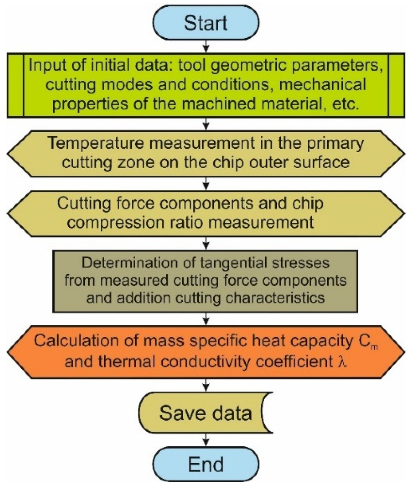
Figure 1. Algorithm flowchart for calculating the thermal parameters of the processed material.
Jmmp 08 00013 g001
Figure 2. Experimental set-up for temperature measurement in the primary cutting zone at the outer surface of the chip.
Jmmp 08 00013 g002
Figure 3. Test set-up for analyzing the drilling process: (a) experimental stand for measuring thermal characteristics; (b) arrangement scheme of thermocouple rows; (c) arrangement scheme of thermocouple layers; (d) short hole drill.
Jmmp 08 00013 g003aJmmp 08 00013 g003b
Figure 4. Test set-up for analyzing the drilling process: (a) arrangement for the temperature measurement on the clearance face of the outer drill insert; (b) short hole drill with measurement field; (c) measurement scheme.
Jmmp 08 00013 g004aJmmp 08 00013 g004b
Figure 5. Initial geometry of the FE model for orthogonal cutting with boundary conditions and mesh combined with the results of modeling the temperature distribution in the cutting zones.
Jmmp 08 00013 g005
Figure 6. Procedure for building the geometric tool model.
Jmmp 08 00013 g006
Figure 7. Initial geometry and boundary conditions of short hole drilling model: (a) geometric model for simulation of temperature distribution in the workpiece; (b) geometric model for temperature simulation in carbide inserts.
Jmmp 08 00013 g007
Figure 8. Effect of cutting speed on chip compression ratio and cutting temperature: (a) change in chip compression ratio; (b) change in cutting temperature.
Jmmp 08 00013 g008
Figure 9. Changing the thermocouple signals during the drilling process: (a) change in the signal of thermocouples in the middle layer of the workpiece, (b) changing the signal of thermocouples in the bottom layer of the workpiece; (c) change in the thermocouples signal in a row with the temperature measuring point positioned at a distance of 1 mm from the drill hole surface; (d) change in the thermocouples signal in a row with the temperature measuring point positioned at a distance of 0.5 mm from the drill hole surface.
Jmmp 08 00013 g009
Figure 10. Workpiece temperature dependence on the position of its measuring point and cutting modes: (a) variation in the workpiece temperature depending on the position of its measuring point, (b) temperature change in the workpiece in its lower layer with varying drill feed; (c) temperature change in the workpiece in its middle layer with varying drill feed; (d) temperature change in the workpiece in its upper layer with varying drill feed.
Jmmp 08 00013 g010
Figure 11. Pyrometer signal development over measurement time and temperature on the lateral clearance face of the outer insert, depending on the drill feed: (a) pyrometer signal development, (b) temperature dependence on the drill feed.
Jmmp 08 00013 g011
Figure 12. Simulation of thermal characteristics in the workpiece during short hole drilling: (a) temperature simulation at the beginning of the drilling process; (b) temperature simulation during the steady state drilling process.
Jmmp 08 00013 g012
Figure 13. Simulation of thermal characteristics in the workpiece and the outer insert during short hole drilling: (a) changing the thermocouple signals during the drilling process; (b) temperature distribution in the drill; (c) temperature change on the lateral clearance face of the outer drill insert over simulation time.
Jmmp 08 00013 g013
Figure 14. Comparison between measured and simulated temperature values in the workpiece and on the lateral clearance face of the outer drill insert at different drill feeds: (a) comparison between measured and simulated temperatures in the workpiece; (b) comparison between measured and simulated temperatures on the lateral clearance face of the outer drill insert.
Jmmp 08 00013 g014
Table 1. Johnson–Cook constitutive equation and friction model parameters [18].
InsertConstitutive ParametersFriction Parameters in Cutting Zones
Secondary ZoneTertiary Zone
A [MPa]B [MPa]n [-]C [-]m [-]Plastic Area, fRFp [-]Elastic Area, fRFe [-]fCF [-]
Outer532.7654.20.26540.021350.850.6530.3240.562
Inner475.9592.60.21450.018120.920.7240.3920.637
General518.5632.40.25610.020480.870.6780.3470.587
Table 2. Thermal properties of the machined material.
InsertThermal Properties of the Machined Material
Mass Specific Heat Capacity Cm [J/(kg °C)]Thermal Conductivity Coefficient λ [W/m °C]
Outer685.419.8
Inner635.717.6
General663.218.3
Disclaimer/Publisher’s Note: The statements, opinions and data contained in all publications are solely those of the individual author(s) and contributor(s) and not of MDPI and/or the editor(s). MDPI and/or the editor(s) disclaim responsibility for any injury to people or property resulting from any ideas, methods, instructions or products referred to in the content.