1. Introduction
Steel–copper composites possess advantageous mechanical properties and connectivity derived from steel, along with exceptional thermal conductivity, electrical conductivity, and diamagnetic properties characteristic of copper. As a result, these composites find wide-ranging applications in various fields, including consumer electronics, electrical engineering, renewable energy sources, and power generation and transmission [
1,
2,
3,
4,
5]. A typical application case of these composites is the connection between the middle plate and the stud of a mobile phone. Welding plays a crucial role in fabricating these composite structures. However, welding steel–copper composites faces significant challenges due to notable disparities in the physical, chemical, and metallurgical properties between copper and steel. These challenges include the restricted solubility of copper in iron and the propensity to generate coarse-grained microstructures [
6,
7].
Numerous efforts have been undertaken to explore diverse methodologies aimed at enhancing the quality of dissimilar metal laser welding between steel and copper. These endeavors focus on mitigating challenges associated with conductivity, reflectivity, and solubility intricacies inherent to copper while concurrently improving joining performance. Yao et al. [
8] introduced a scarf butt laser welding technique for joining steel and copper. This technique involves positioning the steel and copper sides at acute and obtuse angles, respectively, enabling control over the dilution ratio of copper to steel (the relative amount of each melted and commingled in the weld pool) by strategically displacing the laser beam from the centerline of the butt joint towards the steel. Torkamany et al. [
9] explained that the dilution of various steels in the weld pool depends on the specific laser joining mode employed. Esfahani et al. [
10] reported that precise control of the laser beam location allows effective regulation of the mechanical properties of the weldment and the composition of the fusion zone. Addressing concerns regarding high residual stress, elevated microhardness, and the presence of martensitic dendritic microstructures within welded joints, Mai and Spowage [
11] proposed that controlling the dilution ratio of dissimilar metals was one of the most effective approaches for achieving flawless jointing. Laser welding, characterized by high energy density and localized heat input, offers the advantage of mitigating the formation of brittle intermetallic phases. To enhance the microstructural and mechanical properties of weldments, Li et al. [
12] recommended judicious adjustment of the laser deflection angle to eliminate porosity in the fusion zone. Additionally, effective management of heat input was emphasized to reduce the susceptibility to heat-affected zone (HAZ) liquation cracking during laser welding.
Suga et al. [
13] presented a study on the laser welding of SS–Cu lap weldments, focusing on the identification of favorable filler materials and optimal brazing parameters. This joining method demonstrated efficiency and effectively mitigated the occurrence of cracks and other defects. However, the complexity of the technology, attributed to the utilization of filler materials, posed challenges and had implications for the electrical and thermal conductivity of the resulting weldment. In a similar vein, Chen et al. [
14] investigated the microstructure and mechanical properties of laser-welded SS–Cu joints. Their research highlighted two distinct modes of joining: the weld-brazing mode, which involved melting SS onto intact Cu, and the full fusion welding mode, which facilitated the melting and mixing of dissimilar metals. Importantly, the authors demonstrated the controllable conversion between these modes by adjusting parameters such as laser energy input, inclined angle, deviation of the laser beam on the steel, and welding speed.
Moharana et al. [
15] conducted a study on the laser welding of SS–Cu dissimilar metals and made several significant observations. They noted that the interface of the molten pool exhibited an arc-shaped configuration on the SS side, while it appeared as a straight line on the Cu side. Furthermore, the authors observed that the heat-affected zone (HAZ) on the SS side was considerably narrower compared to that on the Cu side, and the grain size within the weld varied depending on the cooling and solidification rate of the molten pool. Through their examination of the metallurgical mechanisms in the fusion zone, they found that the weld penetration ability increased with higher pulse energy. Additionally, they reported that dissimilar welds of SS–Cu were prone to fracture at the fusion zone due to solidification cracks, and the mechanical strength of the fusion zone was even lower than that of the Cu base material [
16]. Cheng et al. [
17] reported that the mechanical strengths of weld joints were lower and exhibited greater elongation compared to the Cu base metal. This reduction in strength was attributed to the softening of the HAZ on the Cu side, induced by the welding process.
In recent years, laser joining thin sheets has garnered significant attention in various industries, particularly in the field of e-mobility. Mehlmann et al. [
18] achieved successful welding of 0.2 mm thick Cu sheets and 0.25 mm thick mild-carbon steel by utilizing a continuous wave laser with linear feed and a superposed circular modulation. Additionally, Patschger et al. [
19] attempted to weld SS with a thickness of 5 μm using a continuous laser. However, they encountered challenges such as burnthrough and thermal deformation due to the continuous heat input. Consequently, researchers have increasingly favored the use of pulsed laser for welding thinner metal sheets, as it provides higher penetration efficiency and depth compared to continuous laser. Kumar et al. [
20] employed nanosecond pulse laser to explore the viability of welding ultra-thin copper sheet with SUS304 SS sheet (40 microns thick) in a lap welding pattern with controlled heat input.
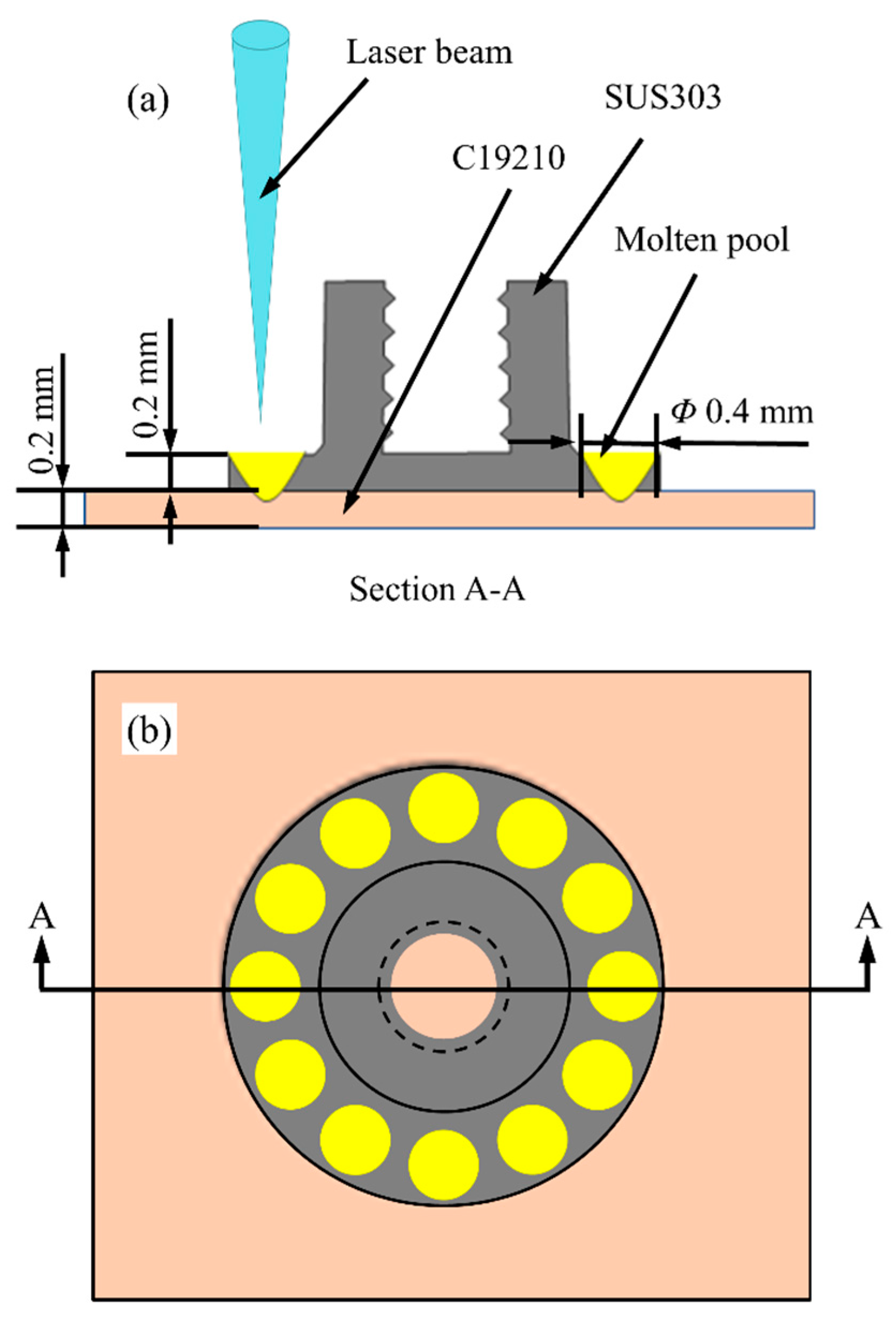
Despite significant progress in dissimilar metal welding of SS and Cu, research on lap welding of thin materials using lasers, which has wide applications in cellphones, is still limited. The primary challenge in joining the middle plate and the stud of cellphones is melting both parts without damaging the surface of the copper middle plate while also ensuring satisfactory mechanical strength. This paper presents current research on microstructure analysis of SS/Cu dissimilar joints using pulsed fiber laser lap welding technology. The impact of laser parameters on the mechanical strength of the weld is reported. Additionally, a detailed analysis on the microstructure, microhardness within the welded region, and fracture characteristics was conducted.
3. Results and Discussion
3.1. Mechanical Strength Dependence on Processing Conditions
The mechanical strength measurements exhibited a significant correlation with the welding parameters employed. To comprehensively evaluate this impact, the tensile and shear strengths of the fiber laser-welded joints were systematically investigated under varying conditions of peak power, pulse width, and pulse energy. The testing was conducted at a strain rate of 1 mm/min and a gauge length of 10 mm.
3.1.1. Effect of Peak Power on the Tensile and Shear Strength
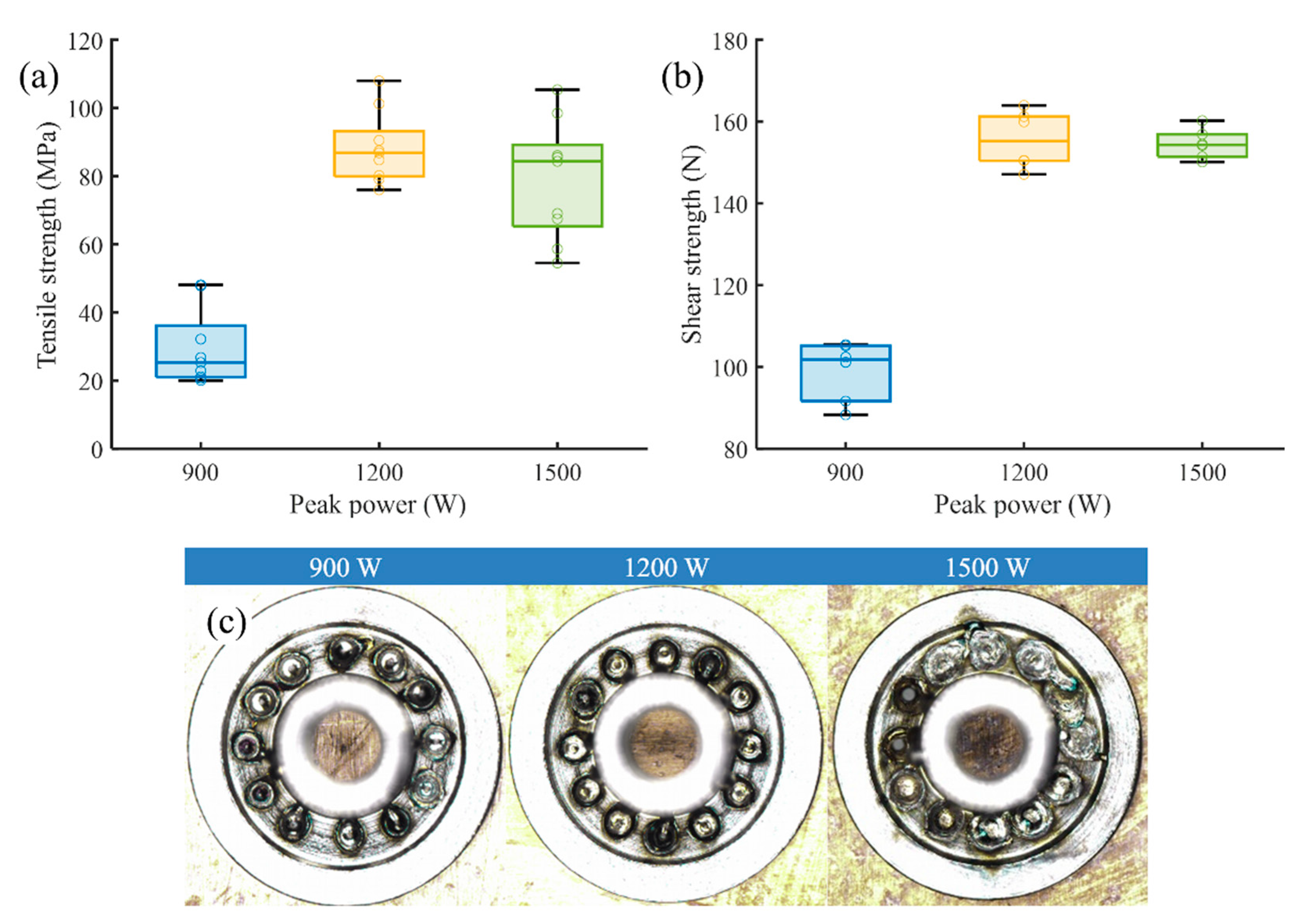
Figure 3 illustrates the impact of peak power on the tensile and shear strength of the joints, where tests were conducted within the range of 900 to 1500 W, employing a fixed pulse width of 11.4 ms with a similar pulse waveform. The focal length was set at 234 mm, the defocus amount at 0, and the spot diameter at the laser focus at 0.4 mm. Both tensile and shear strength exhibited a similar trend, characterized by an initial rapid increase followed by a gradual decline as peak power increased. This result is rational because the influence of weld energy determines the fusion depth achieved by each pulse. Higher peak power resulted in increased fusion depth, thereby improving mechanical strength. However, when peak power was below 900 W, the tensile and shear strength rapidly dropped to zero, indicating insufficient energy to fully weld the upper SS layer and penetrate the copper layer, resulting in an unwelded copper plate. As peak power increased, the mechanical strength gradually improved, suggesting that the tensile and shear forces were enhanced due to the increased fusion depth resulting from higher peak power. Additionally,
Figure 3c reveals that with the increase in peak power, weld spatter gradually increased and the welding edge became more blurred. Nevertheless, excessive welding energy led to partial breakdown of the thin copper layer, formation of welding holes due to spattering, and ultimately reduced tensile and shear strength.
3.1.2. Effect of Pulse Width on the Tensile and Shear Strength
The effect of pulse width on mechanical strength was examined, as shown in
Figure 4a,b, with a fixed peak power of 1500 W and pulse energy of 2.67 W. The obtained mechanical strength trend aligns with the expected relationship between welding energy and pulse width, indicating a positive correlation between pulse width and effective heat energy input per pulse.
Figure 4c demonstrates an increasing trend in weld spatter and blurred welding edges as pulse width increases. Additionally, it was observed that weld depth linearly increased with various pulse widths. This can be attributed to the longer energy input time and increased molten pool melting time as pulse width increases. The enhanced heat conduction facilitates the transfer of more energy to the copper layer, resulting in greater melting depth. Notably, compared to peak power, pulse width variation had a greater impact on weld depth.
3.1.3. Effect of Pulse Energy on the Tensile and Shear Strength
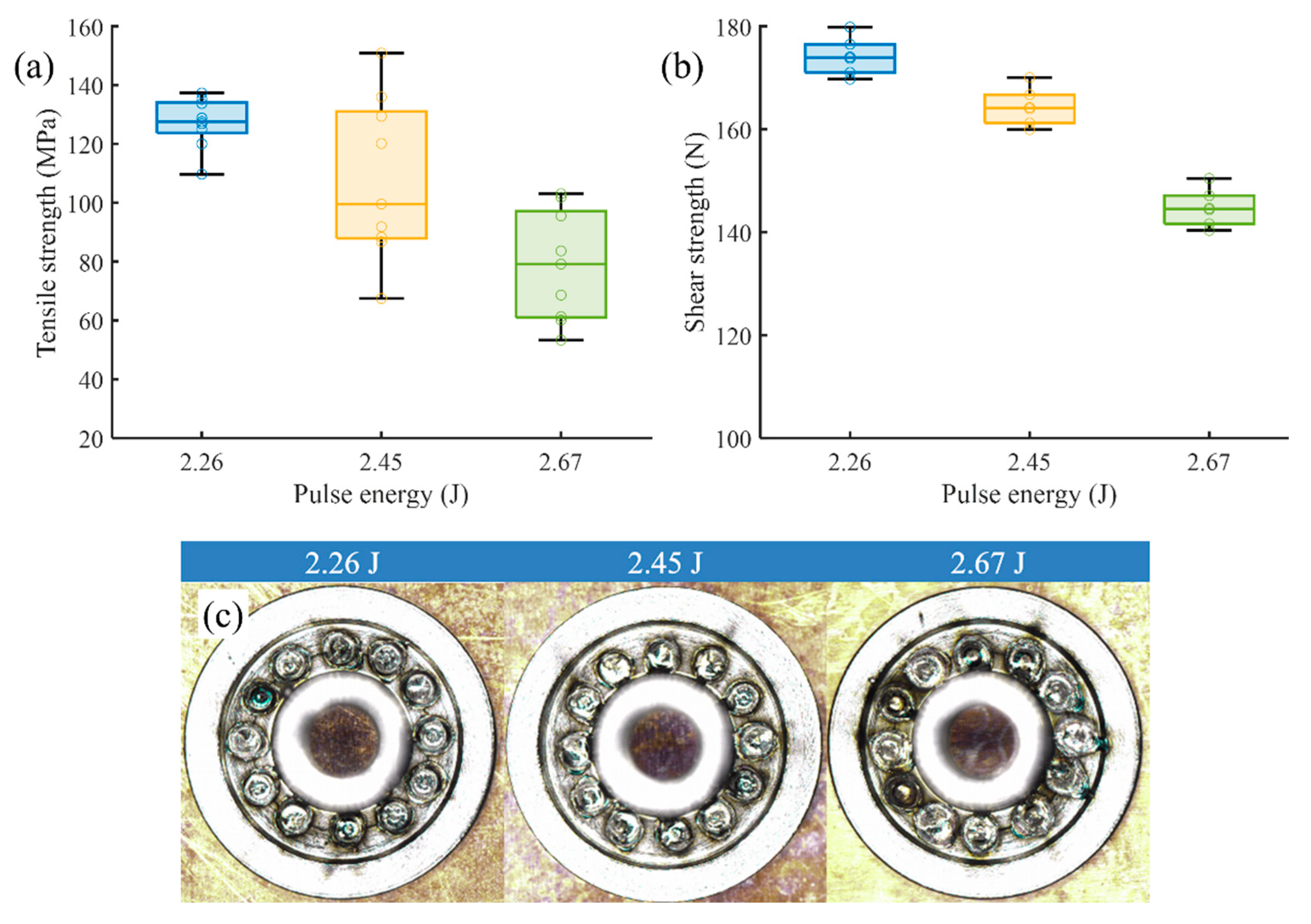
The relationship between mechanical strength and pulse energy was investigated using a fixed peak power of 1500 W and pulse width of 6.2 ms, that is, varying the energy by changing the waveform, as depicted in
Figure 5a,b. The graph illustrates a decrease in mechanical strength as pulse energy increases. Additionally,
Figure 5c reveals an increasing trend in weld spatter and blurred welding edges with higher pulse energy. At a pulse energy of 2.26 W, partial penetration of the thin copper sheet may occur. However, at a pulse energy of 2.67 W, complete penetration of the thin copper sheet was achieved. This was likely due to the higher laser absorptivity of SS compared to copper (approximately 35% for SS and approximately 10% for Cu). This outcome aligns with the expectation that higher energy input facilitates easier penetration. However, as pulse energy was further increased, improved penetration into the copper resulted in the breakdown of the thin copper sheet, leading to a decrease in joint strength.
Consequently, the optimized welding parameters for achieving the highest tensile strength and desirable appearance were identified as follows: peak power of 1500 W, pulse energy of 2.26 J, pulse width of 6.2 ms, frequency of 30 Hz, focal length of 234 mm, and welded joint diameter of 0.4 mm. These specific parameters, denoted as welding parameter OPT, were employed for all subsequent specimens in the study.
3.2. Macrostructure
Figure 6 shows a top view of dissimilar metal weldments joined by pulsed fiber laser with welding parameter OPT. The figure displays a stepped dome-shaped molten pool with a central protrusion, along with outward flow and spreading of the core part. The fusion formation has a convex profile, likely due to surface tension controlling the edges wetted in the molten pool.
Table 3 includes the computed EDS counts of elements derived from the respective EDS maps. The main component on the surface of the molten pool is iron, with copper detected at the #1 and #5 regions in percentages of 8.32% and 3.12%, respectively. These findings suggest that the distribution of Cu on the surface of the molten pool is non-uniform, being limited to specific localized regions. Furthermore, the distribution of other elements on the molten pool surface is also irregular. The highest contents of carbon (38.44%) and oxygen (27.21%) are found in the middle of the molten pool. This phenomenon could be attributed to the high power density and significant oxidation of material in this particular region.
Figure 7 shows a cross-sectional view of the weldment created with the OPT welding parameter. The figure reveals several solidification cracks and pores within the weld joint. These cracks formed in the middle of the molten pool and propagated towards the base metal due to the high cooling rate of copper leading to a high residual stress. Moreover, during the solidification of the molten pool, the presence of low melting eutectics at grain boundaries further promoted the formation of thermal cracks.
On the SS side, the interface between the molten pool and the base metal was clearly visible. The fusion zone exhibited a significant presence of cellular dendrites, with larger grain size compared to the heat-affected zone of the steel. Conversely, on the Cu side, the complete penetration of the SS layer resulted in the melting of Cu, indicating that the melting of Cu occurred through thermal conduction or thermal convection. However, due to the stainless steel’s high absorption of laser energy, only a limited amount of Cu was melted, resulting in a very small quantity of Cu being dissolved in the weld pool.
In the region marked by the red dashed line in
Figure 7b, there existed a transition zone with numerous granular phase regions along the interface between the Cu and the fusion zone. Furthermore, satisfactory welding penetration may also be hindered by contamination of the weld metal surfaces and shorter melting time at the bottom than at the top of the molten pool.
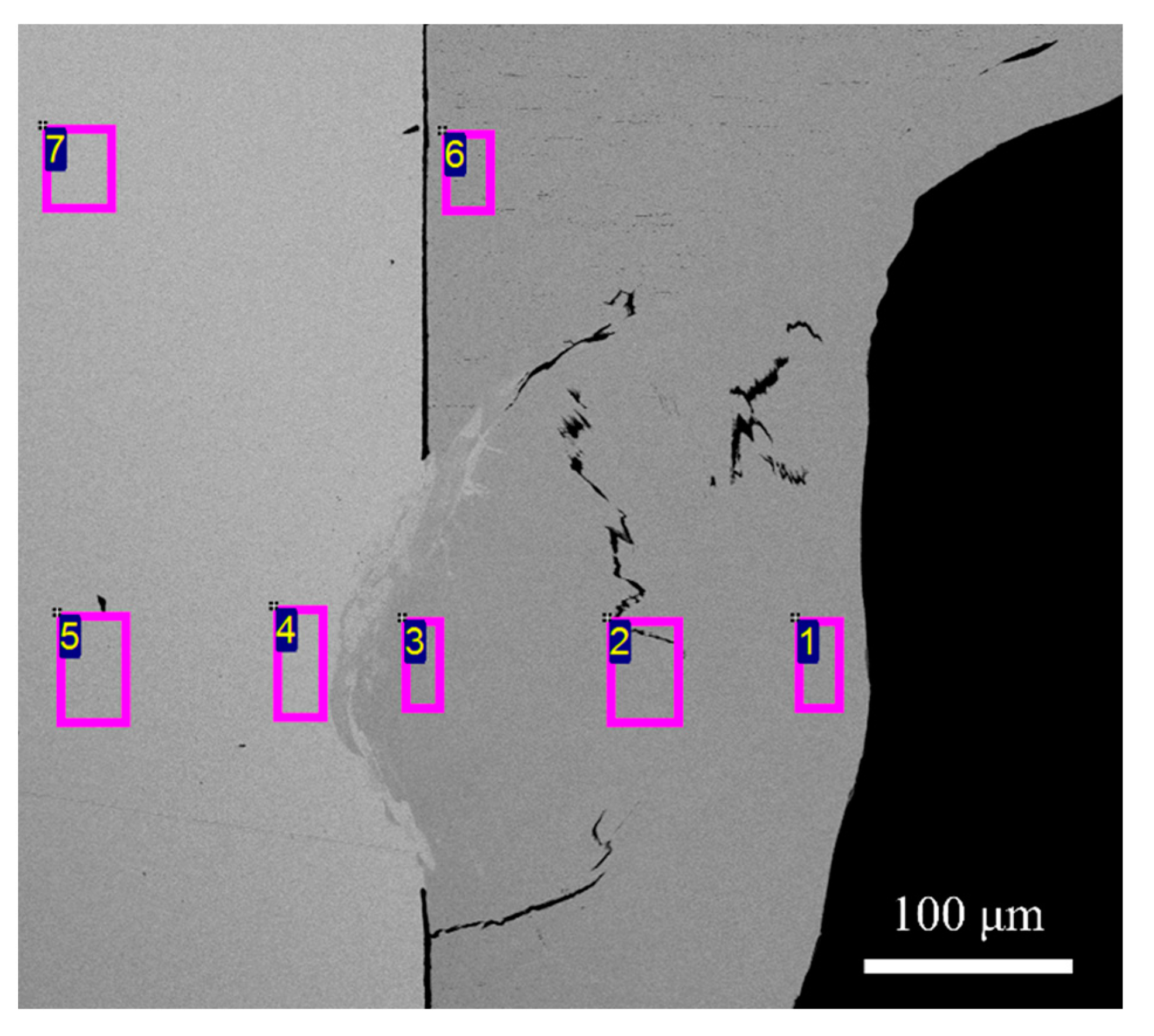
Five points along the central line of the weld pool were analyzed for their chemical composition, as shown in
Figure 8.
Table 4 shows the EDS counts of elements. The EDS analysis revealed the presence of dissolved Cu in the weld pool during laser welding. The highest Cu content (6.45%) was observed at region #3, located probably 40 microns away from the transition zone. This finding indicates that the intermediate layer formation was attributed to the Cu melting through wetting and heat conduction by the molten steel. However, it should be noted that the extent of Cu melting was quite limited.
The EDS line mapping analysis shown in
Figure 9 unveiled a regular variation in the composition ratios of Fe, Ni, Cr, and Mn while transitioning from Cu to SS, with a rapid change observed at the interface layer. Conversely, the composition proportions of Cu exhibited the opposite trend. The primary elements present in the molten pool were Fe, Cr, and Ni, both on the SS side and the Cu side. Although a small quantity of Cu was detected, the fluctuation in Cu content along the fusion line suggests the occurrence of diffusion between Cu and SS at the fusion interface.
The microstructure analysis at the fusion interface of the weldment, as shown in
Figure 10, provided valuable insights into the composition characteristics. The corresponding EDS counts of elements are recorded in
Table 5 and
Table 6. These reveal the presence of a transition zone, which arises from the mutual diffusion of Fe and Cu at the joining interface, resulting in an intricate intermingling of these two elements. The weld on the SS side primarily comprises a significant proportion of Fe along with a minor amount of Cu. The molten pool predominantly exhibits the mutual dissolution of Cu and Fe, manifesting as a two-phase solid solution. This outcome implies that not only did mutual diffusion transpire between the SS and Cu, but there was also dissolution in the liquid state throughout the entire molten pool.
3.3. Microhardness
Microhardness measurements were conducted on a specimen prepared using the optimized welding process parameter, referred to as OPT welding.
Table 1 presents the microhardness values obtained, where pure copper C19210 exhibited a range of 110–135 HV, while SUS 303 SS displayed a microhardness of less than 200 HV. These measurements were carried out under a 100 g load and a 15 s residence time. The distribution of microhardness across the weld regions is shown in
Figure 11.
In the case of the SS side, the microhardness of the molten pool (P2, P3, and P4) was less than that of the weld HAZ (P1 and P5), which, in turn, exhibited higher hardness compared to the base metal. This observation can be attributed to the partial dissolution of liquid Cu into the molten pool, along with the rapid solidification effect during the welding process. The microhardness exhibited an inverse correlation with the redistribution gradients of the copper element. However, on the Cu side, no significant difference in microhardness was observed between the HAZ and the Cu base metal. This phenomenon may be considered a distinctive characteristic of SS/Cu dissimilar metal combination. The fusion zone generated by a high-energy-density pulse laser was provided with a cooling rate of approximately 10
5 °C/s at room temperature [
21]. This rapid cooling rate enhanced the solubility of solutes and facilitated nucleation, resulting in the formation of cellular dendrites. This prevented noticeable segregation and led to the formation of a supersaturated mischcrystal with a new microstructure.
3.4. Fracture
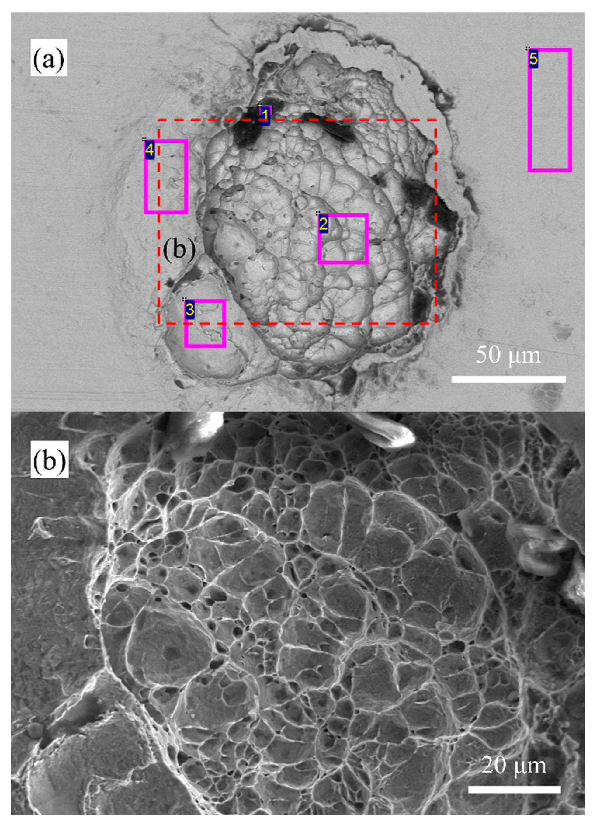
Tensile strength test was conducted on joints using the OPT process parameter. The test were performed in accordance with relevant technical standards. The fracture behavior of the tensile tests was examined using scanning electron microscopy (SEM), as shown in
Figure 12. The EDS counts of elements are recorded in
Table 7. The SEM fractographs clearly indicate the presence of dimpled facets with the coalescence of macro/microvoids, providing strong evidence of ductile failure in the fracture mechanism. Furthermore, the appearance of shallow ridges with a higher concentration of voids and dimples on the fracture surface further confirms the ductile mode of fracture.
The SEM fractographs reveal that the dimples represent traces of concave spherical regions of Cu, which can also be observed in the cross-section of the weldment (
Figure 8). In the case of samples fractured at the HAZ of Cu, this can be attributed to the grain structure in the weld zone. It is notably larger than the grains in the Cu base material zone. This phenomenon occurs primarily due to the rapid growth of crystal grains caused by heat transfer from top to bottom during the welding process. As a result, the strength of the HAZ on the Cu side is significantly reduced, leading to joint failure on the Cu side during the stretching process.
On the other hand, the melting region exhibits sufficient strength due to the formation of solid solutions between Cu and Mn, Cr, Ni, and Fe. This leads to the formation of an intermediate layer with a width ranging from 10 to 30 μm, contributing to the overall strength of the welded joint.
The presence of Mn, Cr, Ni, and Fe was confirmed from the chemical analysis at region #3, which was located at the separation boundary of the intermediate layer and Cu. The presence of oxygen in this zone indicates the oxidation of the material because of the existence of Fe. The EDS analysis results of this fracture point suggest that the intermediate layer was composed of a Cu and SS alloy. The tensile properties of the welded samples were found to be similar to those of the Cu base metal, with only a slightly higher ductility in the Cu material compared to the weldment. This may be due to the amount of austenite in the weldment being increased compared with the Cu metals. The increasing Cr/Ni ratio would lead to the existence of ferrite in the welded solidification area to improve the tensile strength of the welding materials. In addition, tensile strength tests and microhardness tests showed that the strength of this intermediate layer was higher than that of the HAZ of copper.
Although region #4 was also located at the interface of the intermediate layer and Cu, only C and O elements were detected in the analysis. This observation could be attributed to the upper layer of SS not fully penetrating and dissolving into the Cu layer in this region, leading to higher temperatures and subsequent Cu oxidation. The morphological changes observed are a result of plastic deformation occurring during the tensile testing process. In the center of the fracture ductile vortex (region #2), similar to the Cu base metal, the strength of the HAZ on the Cu side was insufficient, and ductile deformation caused the molten pool to break during the tensile test. The presence of elements at region #1 was likely due to contamination occurring at the boundary between the SS and Cu.
Future research will focus on enhancing the mechanical and metallurgical properties of the welded joint between thin SS and Cu in combination.
