Article

Influence of Novel Beam Shapes on Laser-Based Processing of High-Strength Aluminium Alloys on the Basis of EN AW-5083 Single Weld Tracks

by
Florian Nahr
1,2,3,*,
Dominic Bartels
1,2,3,
Richard Rothfelder
1,2,3 and
Michael Schmidt
1,2,3
1
Institute of Photonic Technologies (LPT), Friedrich-Alexander-Universität Erlangen-Nürnberg, Konrad-Zuse-Straße 3-5, 91052 Erlangen, Germany
2
Collaborative Research Center 814—Additive Manufacturing (CRC 814), Am Weichselgarten 10, 91058 Erlangen, Germany
3
Institute of Photonic Technologies, Erlangen Graduate School in Advanced Optical Technologies (SAOT), Paul-Gordan-Str. 6, 91052 Erlangen, Germany
*
Author to whom correspondence should be addressed.
J. Manuf. Mater. Process. 2023, 7(3), 93; https://doi.org/10.3390/jmmp7030093
Submission received: 31 March 2023 / Revised: 28 April 2023 / Accepted: 4 May 2023 / Published: 9 May 2023
(This article belongs to the Special Issue Progress in Powder-Based Additive Manufacturing)

Abstract

:
The commonly used Gaussian intensity distribution during the laser-based processing of metals can negatively affect melt pool stability, which might lead to defects such as porosity, hot cracking, or poor surface quality. Hot cracking is a major factor in limiting production rates of high-strength aluminium alloys in laser-based processes such as welding or the powder bed fusion of metals (PBF-LB/M). Going away from a Gaussian intensity distribution to ring-shaped profiles allows for a more even heat distribution during processing, resulting in more stable melt pools and reduced defect formations. Therefore, the aim of this study is to investigate the influence of different laser beam profiles on the processing of high-strength aluminium alloys by using a multicore fiber laser, allowing for in-house beam shaping. Single weld tracks on the aluminium alloy EN AW-5083 are produced with varying laser powers and weld speeds, as well as different beam profiles, ranging from Gaussian intensity distribution to point/ring profiles. The molten cross sections are analyzed regarding their geometry and defects, and the surface roughness of the weld tracks is measured. By using point/ring beam profiles, the processing window can be significantly increased. Hot cracking is considerably reduced for weld speeds of up to 1000 mm/s compared to the Gaussian beam profile. Furthermore, the melt pool width and depth are more stable, with varying parameters for the point/ring profiles, while the Gaussian beam tends to keyhole formation at higher beam powers. Finally, a strong decrease in surface roughness for the point/ring profiles, accompanied by a significantly reduced humping effect, starting even at lower beam powers of 200 W, can be observed. Therefore, these results show the potential of beam shaping for further applications in laser-based processing of high-strength aluminium alloys.

1. Introduction

Over the last few decades, the laser beam as an energy source has taken a spot in the metals processing and manufacturing industry due to its high accuracy and versatility, while simultaneously reducing cycle times [1,2]. Utilizing a laser beam in welding provides a precise weld track with a minimal heat-affected zone combined with higher welding speeds compared to traditional processes [1]. Another major application of lasers in manufacturing exists in the powder bed fusion process (PBF-LB/M) for producing metallic parts. In PBF-LB, the component is built layer-wise by melting a thin bed of powder using the laser beam. For these applications, single-mode fiber lasers are the most commonly employed laser sources because of their high energy efficiency and beam quality, among other reasons [3]. Single-mode lasers in PBF-LB/M provide a Gaussian intensity distribution with spot diameters ranging from 40 µm to 120 µm, which is suitable even for fine structures. However, the Gaussian beam profile exhibits severe limitations, such as a high central peak intensity, leading to an overheating at the center of the generated melt pool [3,4]. Subsequently, the material is not only molten but also vaporized, resulting in rapid fluctuations at the melt pool surface, thus leading to spatter formation. Furthermore, the vapor generated at the melt pool surface can affect the recoil pressure applied on the melt pool, leading to a transition from conduction to keyhole mode. Another side effect of these nonuniform thermal conditions is distinct Marangoni flows, which depend on the surface tension caused by temperature gradients between the center and edge of the melt pool [5,6]. These characteristics can have negative consequences on the part quality, resulting in defects such as pores or cracks. The complex interactions between fluid dynamics, geometry, and surface tension of the melt pool can further result in humping or balling defects during welding or PBF, respectively. Humping is characterized by the accumulation of melt in the form of droplets on the weld surface [7]. It occurs at high weld speeds due to the melt stream being directed towards the end of the melt pool. Consequently, the hump is formed by the stagnation pressure of the oncoming melt against the already-solidified material in combination with surface tension [7,8]. The balling phenomenon, on the other hand, refers to the formation of spherical droplets isolated from each other throughout the melt track. It is related to the size and geometry of the melt pool in single tracks. If the melt pool exceeds a defined length-to width-ratio, which can be caused by high scan speeds, the spherical shape is energetically more favorable, leading to the decomposition of the melt track [9].
One attempt to reduce the number of drawbacks from Gaussian beam profiles is the defocusing of the laser beam, leading to less overheating in the core region, as well as a more uniform temperature distribution [10,11]. While already used in laser welding for several decades [12], recent studies by Metelkova et al. [10] have shown a significant impact of defocused beams on the productivity of stainless steel in PBF-LB. Similarly, Sow et al. [13] observed improvements in process stability and spatter reduction, but these effects highly depend on the defocusing distance, as proven by Paraschiv et al. [11]. However, defocusing the Gaussian laser beam only lowers the peak intensity, while the overall shape of the intensity distribution stays the same. Furthermore, operating the laser beam far outside its Rayleigh length can lead to process instabilities, since the beam diameter is highly sensitive to disturbances [4]. Therefore, extended research has been conducted on the effects of beam shaping in both welding [14,15,16,17,18,19] and PBF-LB [20,21,22,23,24]. Abadi et al. [19] verified a lower temperature gradient for elliptical beam shapes used in laser welding. Furthermore, by elongation along the weld travel direction, a vortex is created at the weld pool front assisting in preheating and increased penetration depth. This effect on the melt pool depth was further proven by Ayoola et al [15]. Rasch et al. [14] investigated the effect of different beam profiles for heat conduction welding, leading to larger processing windows and better surface quality when using ring-shaped profiles. In PBF, on the other hand, Okunkova [25,26] compared Gaussian and flat-top beam profiles on single melt tracks, while Metel et al. [22] went one step further and observed an increase in productivity for both flat-top and doughnut-shaped beam profiles. Similarly, Wischeropp et al. [20] achieved larger processing windows for AlSi10Mg in PBF-LB/M using a doughnut-shaped profile. Furthermore, Grigoriev [27] showed reduced evaporation losses by applying a ring profile, and Cloots et al. [21] investigated the effect of Gaussian and ring profile on crack formation.
There are different approaches to change the intensity profile of the laser. In static beam shaping, diffractive optical elements [14,16,20] or lenses [21] can be used to achieve a non-Gaussian intensity distribution. Another approach is dynamic beam shaping techniques such as spatial light modulators [28], which can achieve time-varying intensity distributions. However, both approaches share the necessity to redesign the optical path for implementation. Recent developments in the industry have led to the introduction of multiple-core fiber lasers, which offer the capability for in-source dynamic beam shaping. One of these lasers is the AFX-1000 laser from nLight [29,30]. It enables switching from Gaussian intensity distribution to different point/ring-shaped beam profiles by shifting the intensity distribution between an inner and outer core [4,29,31]. Previous studies regarding the application of the AFX-1000 laser showed an improvement towards larger processing windows for the steel 316L on the basis of single weld tracks [31]. Similar effects were shown for aluminium alloy AlSi7Mg [3] and nickel-base alloy 625 [32] in PBF-LB/M. Furthermore, the first experiments for Ti6Al4V revealed spatter reduction during processing, which could reduce defects and feedstock contamination [33].
One application method for beam shaping is high-strength aluminium alloys, which are used in lightweight structures in the automotive or aircraft sector [34,35]. Processing aluminium alloys with a laser beam is generally more difficult due to their high reflectivity or high thermal conductivity [36]. Furthermore, high-strength aluminium alloys, such as EN AW-5083, are prone to hot cracking in laser processes [37]. This is caused by the shrinkage coupled with the interdendritic liquid at the interface when columnar grains grow during solidification [34,38]. Therefore, the hot cracking sensitivity depends on the chemical composition [39], since alloying elements can differently affect the solidification rate. Existing countermeasures to reduce hot cracking are high-temperature preheating [40] or the alloying of the powder for processing in PBF-LB/M [41]. The introduction of beam shaping through the AFX-1000 laser could have positive effects on productivity. Studies showed an widening of the processing window for aluminium alloys using a ring-shaped beam profile for welding [14,17] and in PBF [3,20]. The increased processing windows for aluminium alloys, both in welding and PBF, by Rasch et al. [14] and Wischeropp et al. [20] have already been described. Maina et al. [42] found a more uniform temperature distribution, and hence a more stable weld process for the aluminium alloys. Furthermore, no keyhole effect or gas porosity were observed compared to a Gaussian beam profile.
The aim of this study is the qualification of different point/ring beam shapes for the laser-based processing of high-strength aluminium alloys. Single weld tracks with beam profiles ranging from Gaussian beam to an intensity distribution of 10/90 between the core and ring are welded onto an EN AW-5083 substrate plate. Subsequently, the melt pools are investigated regarding defects and geometrical differences between the applied beam profiles. The surface of the weld tracks is analyzed regarding quality and roughness. Finally, an outlook is given for the further use of the point/ring-shaped beam profiles in the laser-based processing of high-strength aluminium alloys.

2. Materials and Methods

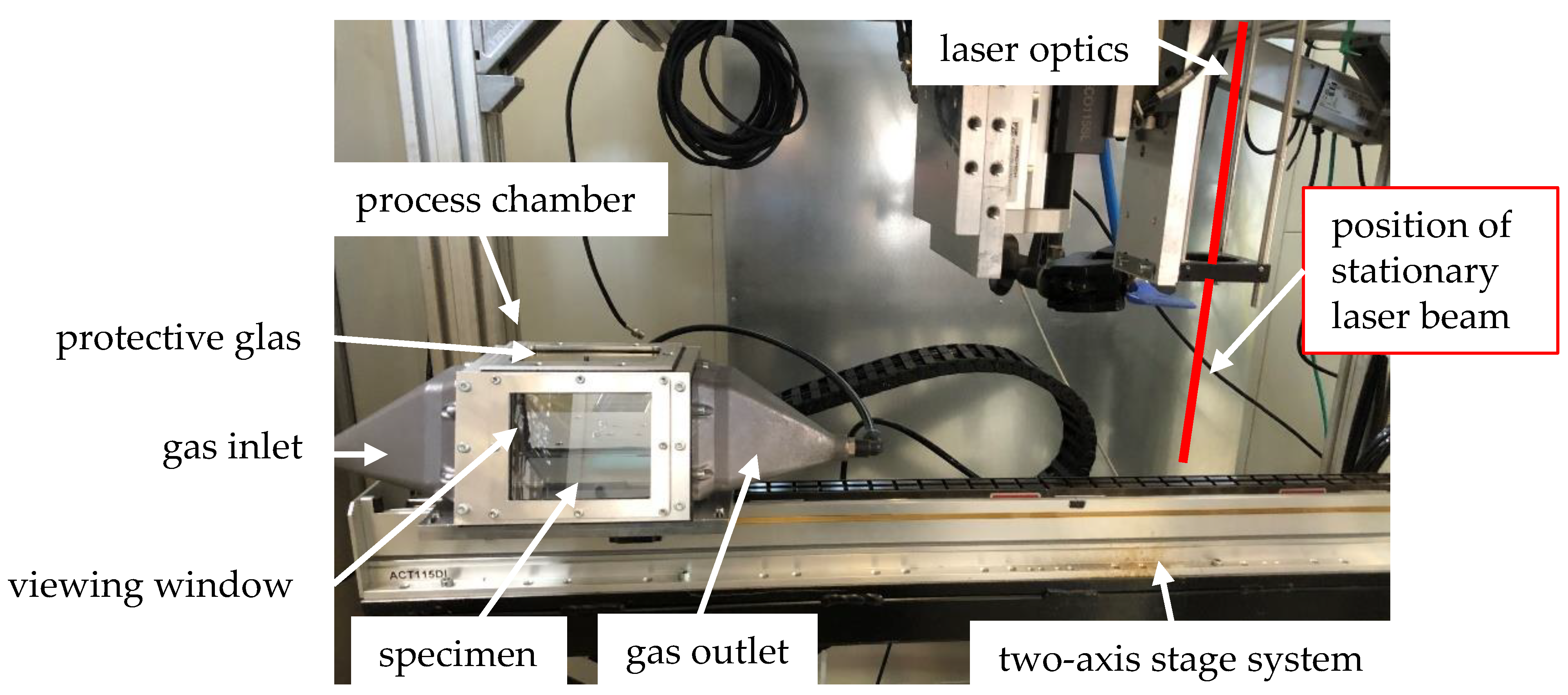
2.1. Experimental Setup

The experiments were carried out on a self designed set-up consisting of a test rig combined with a small process chamber, as shown in Figure 1. The chamber was equipped with a gas inlet and outlet to secure a constant argon gas flow of 7 L/min to prevent oxidation of the weld track. Furthermore, an exchangeable 1 mm thick germanium cover glass was placed 11 mm above the specimen. The test rig included stationary custom optics with a collimation unit and an f-theta length with a focal length of 420 mm, which was mounted at a fixed position on a welding desk. The process chamber was attached to an axis system, which allowed for precise movements in x-,y-, and z-directions of the entire chamber. To ensure a constant velocity of the chamber below the welding optics, an acceleration and deceleration section before and after the position of the stationary laser beam, respectively, were implemented. Compared to the varying angles of incidence caused by the scan field of a PBF-LB machine, the test rig exhibited a constant incidence angle throughout the experiments.
The aluminium alloy EN AW-5083 was used as a substrate with the composition of the alloy, according to DIN EN 573-3 [43], depicted in Table 1. The substrate consisted of an annealed and slightly work-hardened sheet metal. Specimen with the dimensions of 105.0 mm × 50.0 mm × 5.0 mm was taken out of the plate via laser cutting and subsequently sandblasted to a surface roughness of S A = 1.8 ± 0.2 µm before being placed inside the process chamber.
The beam source was an AFX-1000 from nLight, Inc. (Vancouver, WA, USA) with an operating wavelength of 1070 nm and a maximum laser power of 1200 W. The AFX laser was equipped with a single-mode center core surrounded by an annular core. By partitioning the power output between the center and annular core, seven spatial beam profiles could be programmed to shift the intensity distribution from Gauss to a ring shape. The causticity and characteristics of the beam profiles were measured with a MicroSpotMonitor from PRIMES GmbH (Pfungstadt, Germany), and are shown in Table 2.
To cover a large variety of power ratios, Indices 0, 3, 5, and 6 were chosen for the experiments. Therefore, Figure 2 shows the measured intensity distributions at 200 W laser power for the chosen beam profiles as 2D maps, as well as cross sections. The associated spot diameters and characteristics can be gathered from Table 2. While Index 0 represents a true single mode, and therefore Gaussian intensity distribution, the power ratio is gradually shifted to the outer ring for higher indices, leading to point/ring profiles. Finally, Index 6 has a ring shaped profile, with the highest power distribution over the annular core. It is notable for Indices 5 and 6 that the central peak is not uniform but exhibits a slight partitioning. Furthermore, it can be seen that the beam becomes larger with the increasing index.

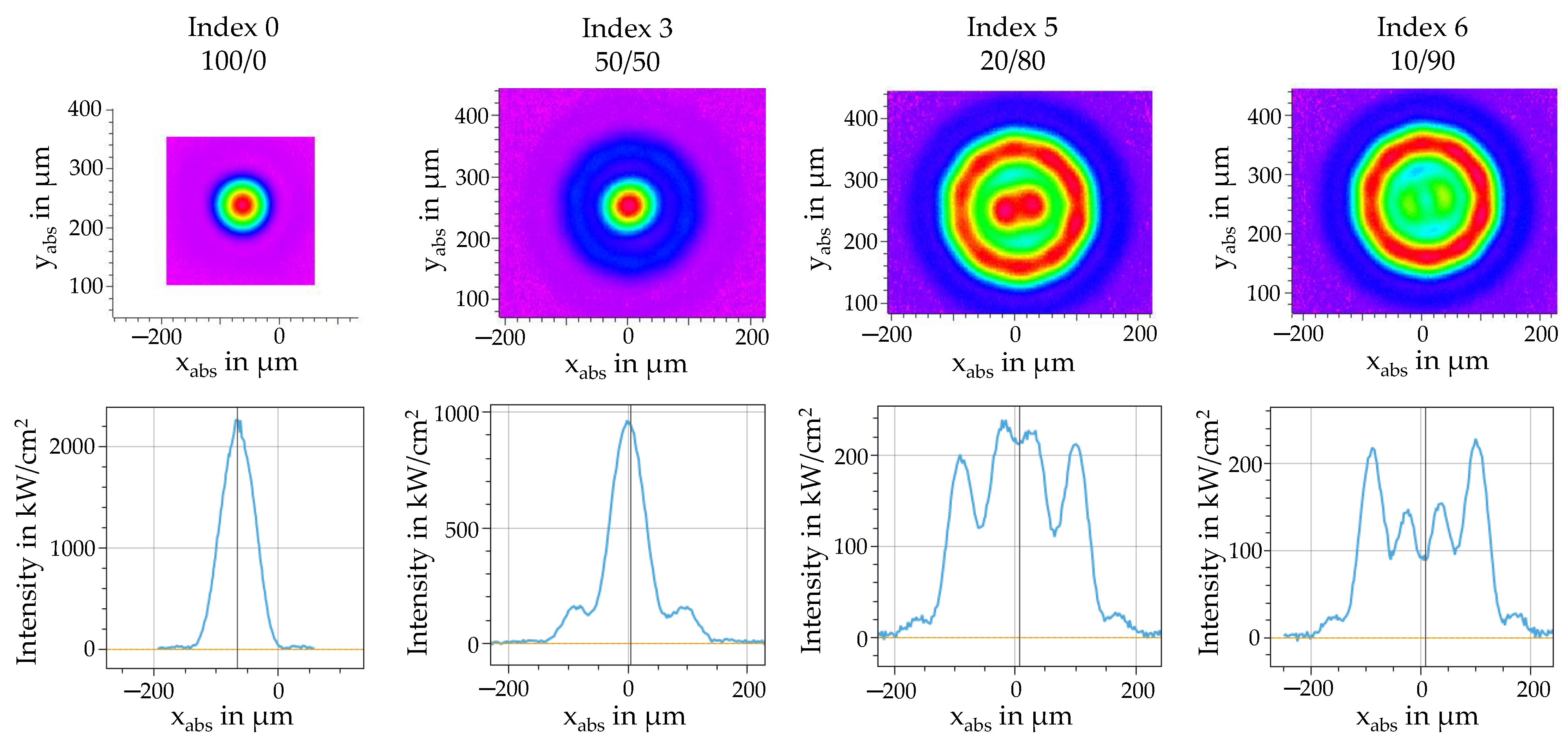
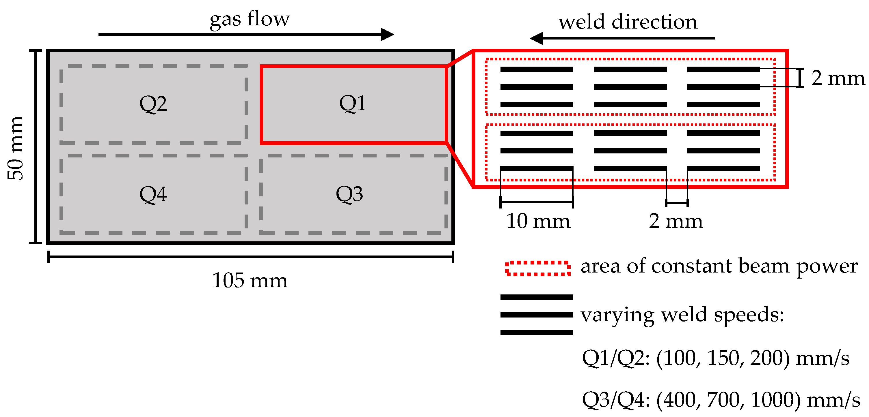
2.2. Process Parameters

Table 3 shows the parameters used in the experiments. They were split into parameter sets 1 and 2, consisting of lower (1) and higher (2) welding speeds. The respective laser power was varied between the parameters. For each chosen beam profile (0, 3, 5 and 6), experiments with every parameter set were carried out.
The location and design of the weld tracks on the specimen is depicted in Figure 3. The surface of the specimen was divided into four quadrants, with each quadrant consisting of two regions of constant beam powers and three different weld speeds. Three tracks with the same beam power and speed were welded in a row before the power was varied, while the weld speed was kept constant. Each parameter combination was welded three times. In summary, 72 weld tracks were produced for each index.

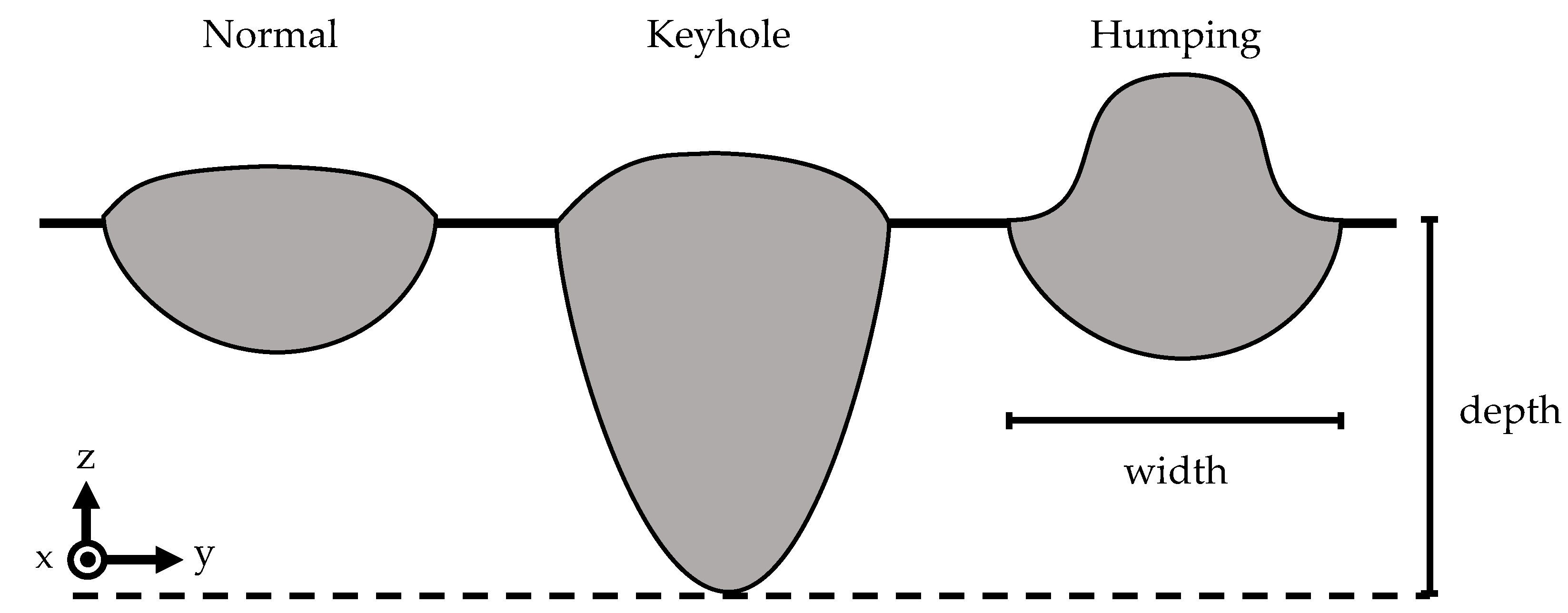
2.3. Characterization

The surface of the single weld tracks was analyzed using a 3D profilometer of type Keyence VR-6000 from Keyence (Osaka, Japan). The profilometer used fringe projection for optical measurement of the surface, which enabled a description of the whole topography, and thus the evaluation of the associated roughness. Since the surface morphology of the weld tracks varied significantly for the different intensity distributions, no standardized cut-off value according to DIN EN ISO 4288 [44] could be used to determine the surface roughness R a or S a . Therefore, the arithmetical mean height of the primary profile P a was chosen to ensure sufficient comparability between the different beam profiles. For characterization of the melt pool quality and dimensions, the specimen was cut in the middle of each weld track. The cross sections were embedded and subsequently ground (P220-P1200), as well as polished with 6 µm and 3 µm diamond suspension, respectively, followed by a finish with an active oxide polishing suspension (OPS). After each step, the specimen was cleaned in an ultrasonic bath. To reveal the melt pool geometry, the samples were etched with H 2 O (200 mL), 65 % HNO3 (1.6 mL), 32 % HCl (0.5 mL), and 40 % HF (1.5 mL) for 10 s, followed by a 30 min exposure to air. The etched cross sections were investigated with an optical microscope, Olympus BX53M from Zeiss (Oberkochen, Germany). The molten cross sections of the weld tracks were analyzed regarding their quality, shape, and the existence of cracks. As shown in Figure 4, distinctions were made between a normal shape, key holing, and humping. The latter is marked by a significant bulge in z-direction. Finally, the melt pool width and depth were determined.

3. Results and Discussion

In the following section, the effects of the different beam profiles on the weld properties are evaluated critically. First, the melt pool dimensions are quantified before the quality of the molten cross-sections is discussed. Furthermore, the surface quality and roughness of the melt tracks is investigated. Finally, the results are discussed with regard to the qualification of the AFX-1000 laser for the PBF of high-strength aluminium alloys.

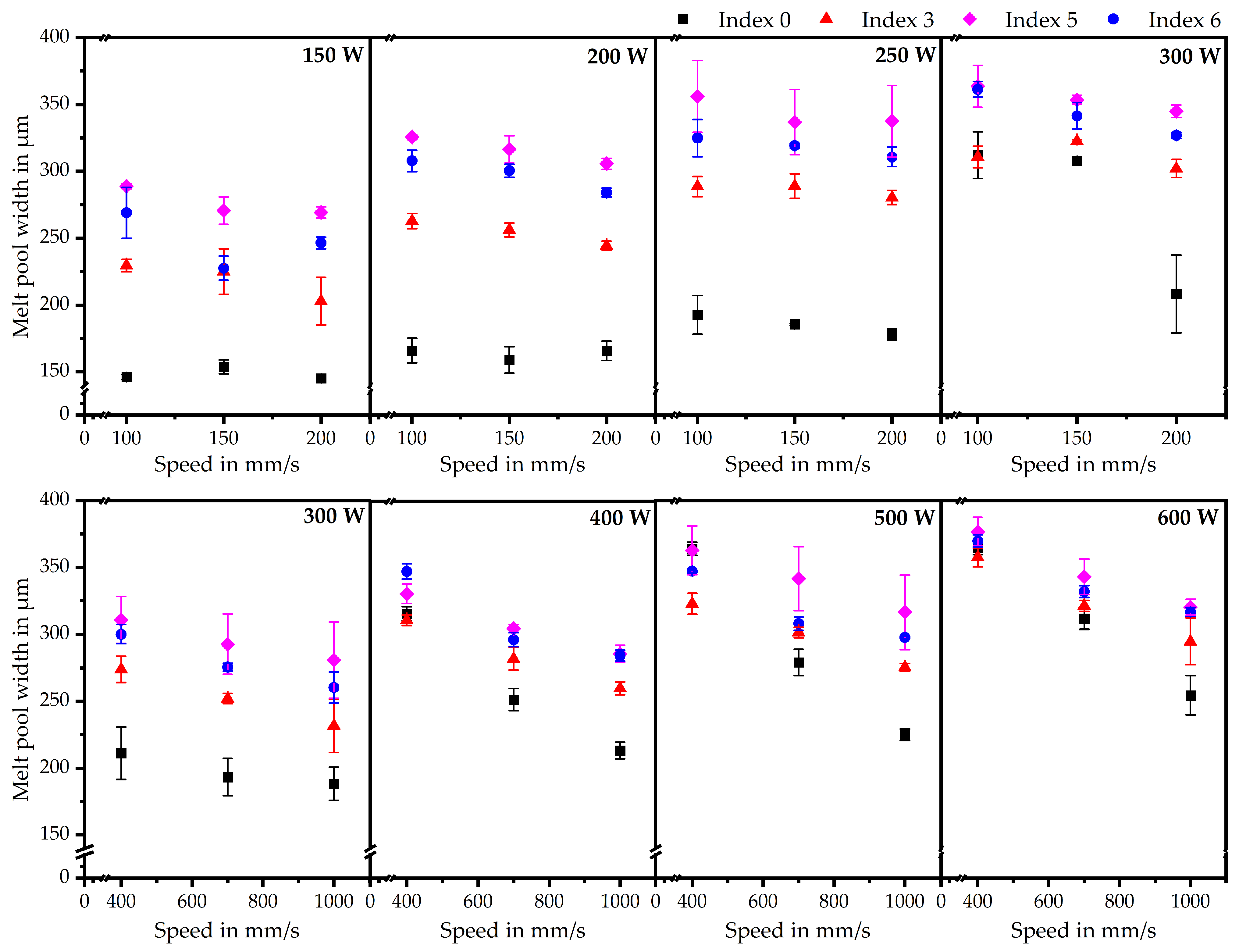
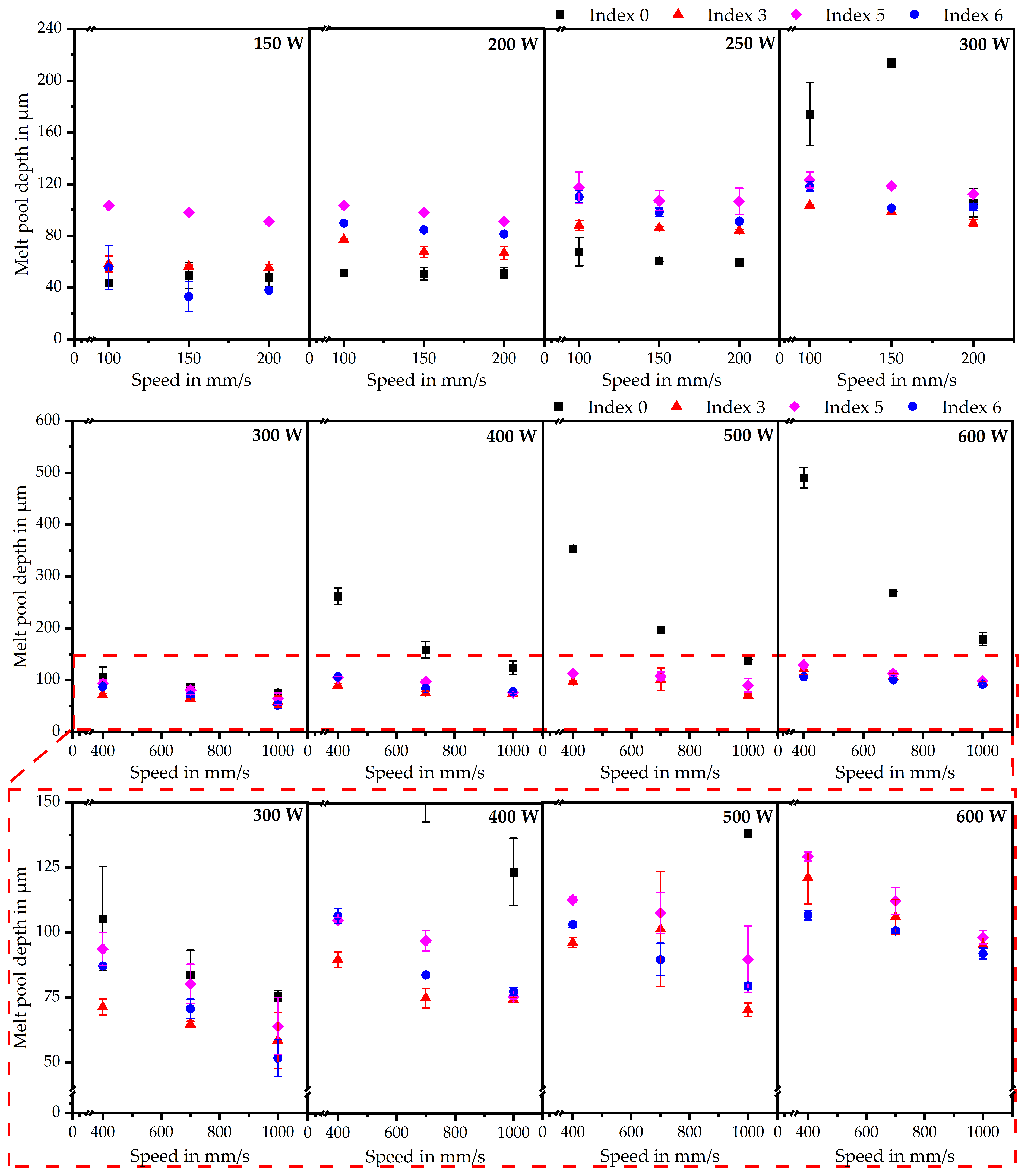
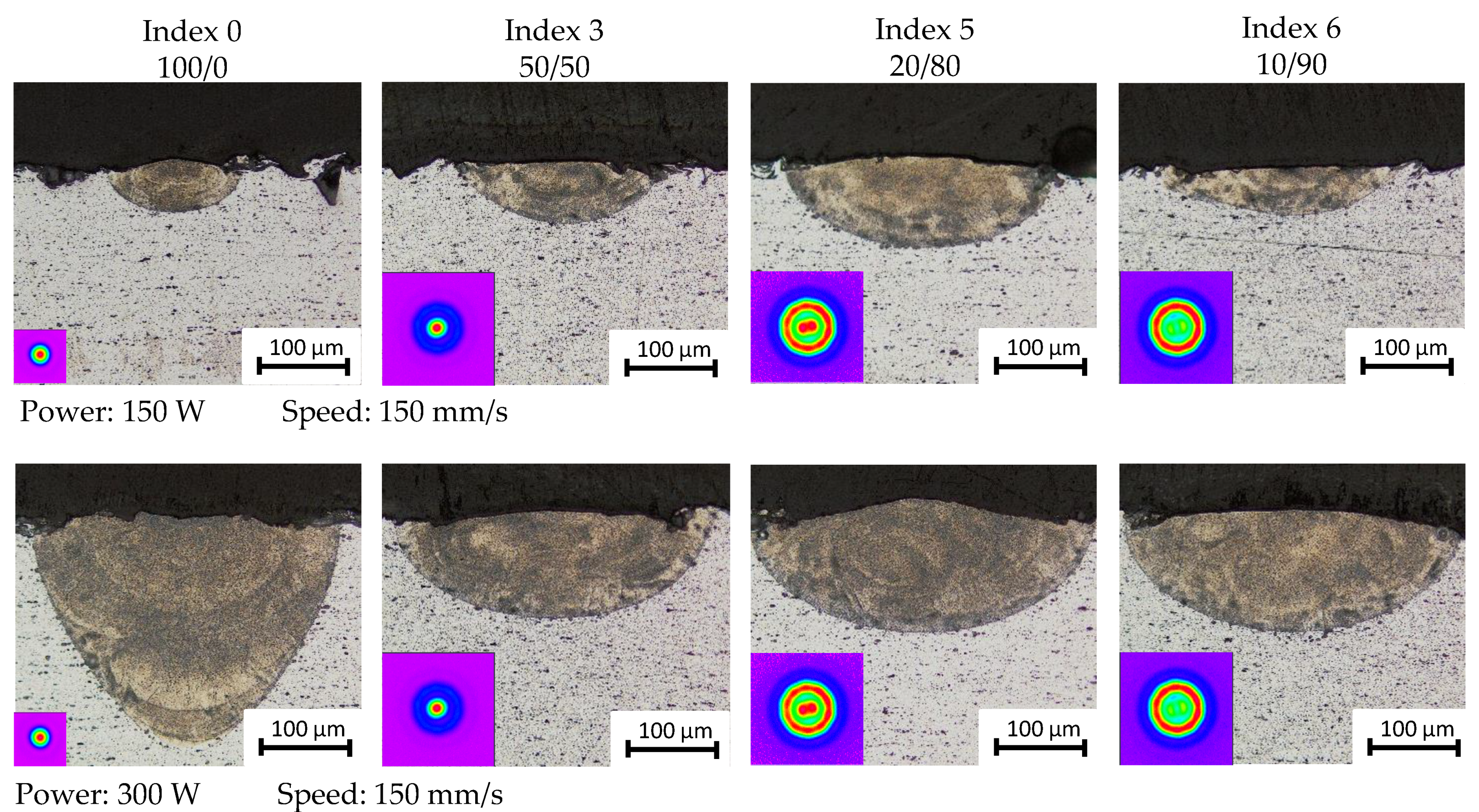
3.1. Melt Pool Dimensions

Figure 5 and Figure 6 show the melt pool width and depth for the different beam profiles. All molten cross sections decrease in width, with increasing weld speeds. A similar trend can be observed at higher beam powers. Furthermore, the Gaussian beam profile has the smallest width compared to the other beam profiles. This effect is not surprising, since the Gaussian beam has the smallest spot diameter and no additional heat input at the outer ring. Therefore, the width of the melt pool only depends on the heat flux from the smaller core region to the outer areas. The difference in width between Index 0 and the other indices is especially distinct for smaller beam powers, while the gap is closing with increasing power and weld speed. Comparing only the point/ring profiles shows Index 3 having the smallest melt pool width. Interestingly, Index 5 has an almost constantly broader melt pool compared to Index 6, despite having less intensity in the outer ring and a slightly smaller spot diameter.
The penetration depth follows a similar trend as the melt pool width, which offers two noteworthy observations. First, at low beam powers, the Gaussian distribution exhibits a more shallow melt pool compared to the point/ring distributions. This is unsuspected, since the smaller spot size combined with the significantly higher intensity in the core should lead to a higher penetration depth. However, this trend does not keep up for higher beam powers where the Gaussian beam clearly has the deepest melt pool. Secondly, Index 5 has the greatest melt pool depth among the point/ring profiles, with Index 6 as a close second, with the exceptions at 150 W and for the highest beam powers. These values correlate well with the results for the width. Nevertheless, similar to the Gaussian beam profile, it is unsuspected that Index 3 exhibits the most shallow melt pool among the ring-shaped profiles, despite having the highest centralized peak intensity. Therefore, Figure 7 shows the molten cross sections of the different indices for low speeds and beam powers. In addition to the geometrical features already discussed, the differences in melt pool shape between Index 0 and the other indices at 300 W are of interest. The melt pool converges more steeply towards the penetration depth, whereas the other melt pools possess a rather oval shape. This effect results from a temperature gradient caused by the broader spot diameter and a more uniform intensity distribution in the outer areas. The results compare well with existing literature [3,45], with the exception of the penetration depth. Similar effects can be seen in the studies by Grünewald et al. [31], who investigated the effects of the AFX-1000 laser on AISI 316L. This leads to the assumption that this anomaly is not caused by the material, but rather by the intensity distribution of the AFX-1000 laser. An explanation could be different Marangoni flows caused by the thermal regimes in the melt pool. Mills et al. [5] showed various Marangoni flows in regard to the surface tensions. Since the surface tension is directly correlated to the temperature, different thermal regimes in the zone between the central intensity peak and the other ring peaks could lead to heat accumulation pushing the melt down, and therefore enlarging the melt pools. For the Gaussian beam, on the other hand, the heat can dissipate to the outer areas without an intensity barrier. However, at a certain power threshold, the intensity in the peak creates severe overheating in the central area. This can lead to keyholing, and Mahangoni flow again pushing the melt to the bottom, leading to a deeper penetration depth. According to Figure 6, this threshold lies at 300 W for both low and fast weld speeds.

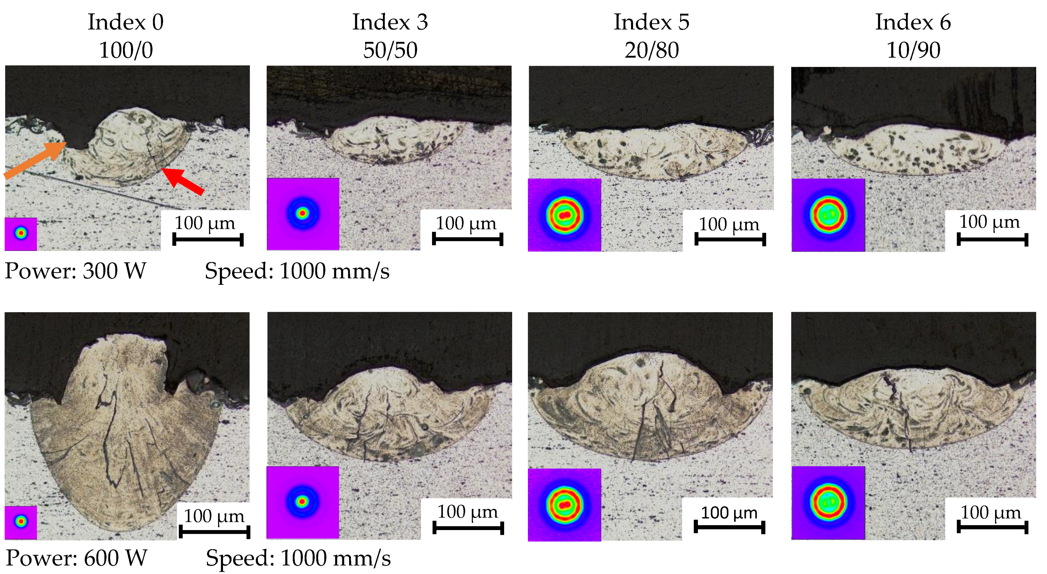
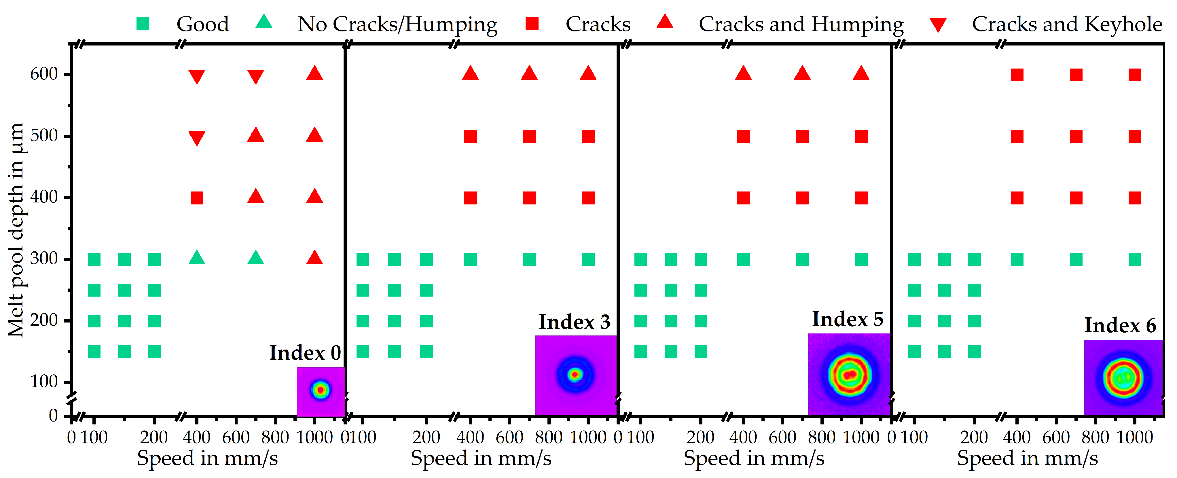
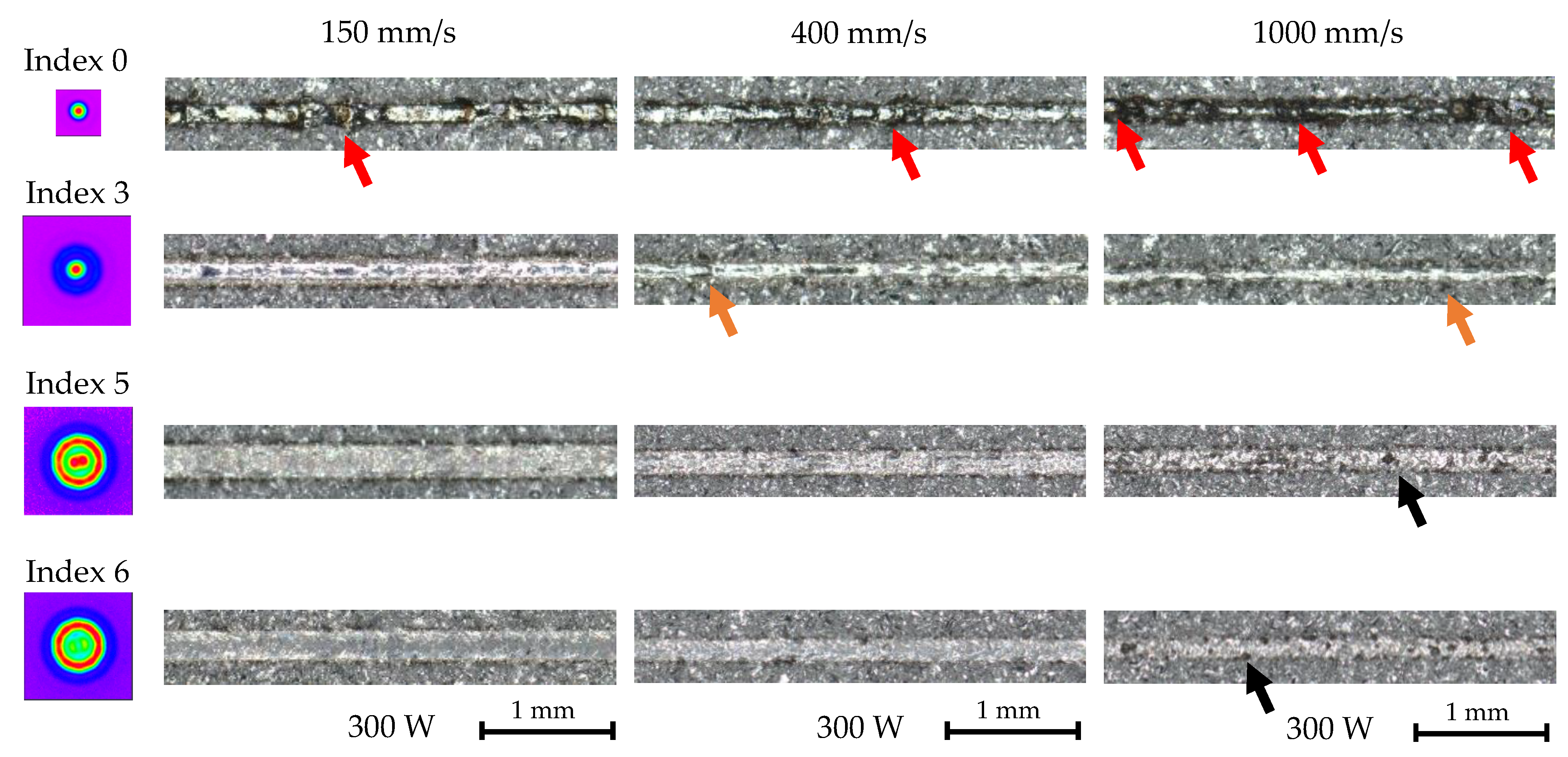
3.2. Melt Pool Quality

After quantification of the melt pool dimensions, the molten cross sections are investigated regarding their defects to establish a processing window for weld tracks of good quality. Therefore, Figure 8 shows the molten cross section for the different beam profiles at the highest weld speeds applied in the experiments. The melt pool shape at the surface, as well as the defects, vary greatly between the Gaussian beam profile and point/ring profiles. However, similar to low scan speeds and powers (Figure 7), the differences are smaller between them with the shift in intensity from core to ring. The Gaussian beam profile exhibits visible cracks in the weld center for both beam powers. Furthermore, for 300 W, a slight depression (orange arrow) and a small spherical bulge can be observed. The bulge increases significantly in size with higher beam power. In combinations with slight but notable depressions at each side, strong indications towards pronounced humping can be made. The melt pools for the point/ring-shaped profiles, on the other hand, show no defects at 300 W beam power, but similar to the Gaussian profile, cracks are formed with an increase in power, although they are smaller in size. Indices 3 and 5 further depict the formation of small humps at 600 W growing stronger in size with a further shift in power towards the ring. Interestingly, the bulge decreases again for Index 6.
Figure 9 compares the processing windows for different beam profiles according to their melt pool quality. Therefore, the melt pools are classified in regard to their geometry as well as for the existence of cracks, as seen in Figure 4. For low speeds and beam powers, all beam profiles appear to be of good quality, with no hot cracks or other defects. However, for high speeds and beam powers, the molten cross-sections show an increase in defect formation, as already depicted in Figure 8. Nevertheless, neither the humping nor the cracks for the ring/point profiles are as severe as for the Gaussian beam profile. As shown by Hollatz et al. [17], applying a ring profile leads to an in situ preheating and postheating. This causes an extension of the melt pool in front of—and especially behind—the center, leading to a more even temperature distribution. Similar results were obtained by Ayoola et al. [15] and Abadi et al. [19] for elliptical and defocused laser beams. This effect, in combination with the greater beam diameter, could result in less stress within the weld track, thus preventing hot cracking. The explanation for the hump formation for the beam profiles on the other side could be similar to the penetration depth. The temperature in the transition zone between the core and ring is higher due to heat accumulation caused by the intensity distribution and heat flux, therefore affecting the surface tension. According to Tang et al. [46] low surface tension may exacerbate the humping effect by causing the ejection of molten droplets. Furthermore, the Marangoni shear force promotes humping formation, since the inward flow can slightly increase the contact angle between the melt and substrate plate. The humping decreases for Index 6 since the temperature in the transition zone decreases in comparison with Index 5, and the beam power in the center is not as high as for Index 3, which could further promote the formation of a hump.
Overall, the analysis of the melt pool quality shows a positive influence of the point/ring-shaped profiles on the processing of EN AW-5083, especially at higher weld speeds. However, the transfer to other classes of high-strength aluminium alloys, which are prone to hot cracking, has to be discussed. For one instance, the thermal conductivity varies significantly between different aluminium alloys. While EN AW-5083 has a thermal conductivity of 110–140 W/mK (EN AW-5083) [47], other alloys, such as EN AW-6082, for example, lie within the range of 170–220 W/mK (EN AW-6082) [48]. Since a higher thermal conductivity of the material leads to increased cooling rates during processing, this could affect the hot cracking tendency. Higher cooling rates, and therefore a faster solidification rate, can result in higher residual stresses throughout the weld track [49], thus promoting cracks. Furthermore, faster solidification could lead to less time for the interdendritic fluid flow to compensate shrinkage and strain. Another difference between the alloys is the chemical composition. As described in [39], varying amounts of certain alloying elements such as Si, Mg, or Cu used in high-strength aluminium alloys can further promote hot cracking. Therefore, the transferability of the results for EN AW-5083 is limited. However, positive effects of the point/ring-shaped profiles, such as more even heat distribution, should still apply, as shown by previous studies [14,17,31] for beam shaping.

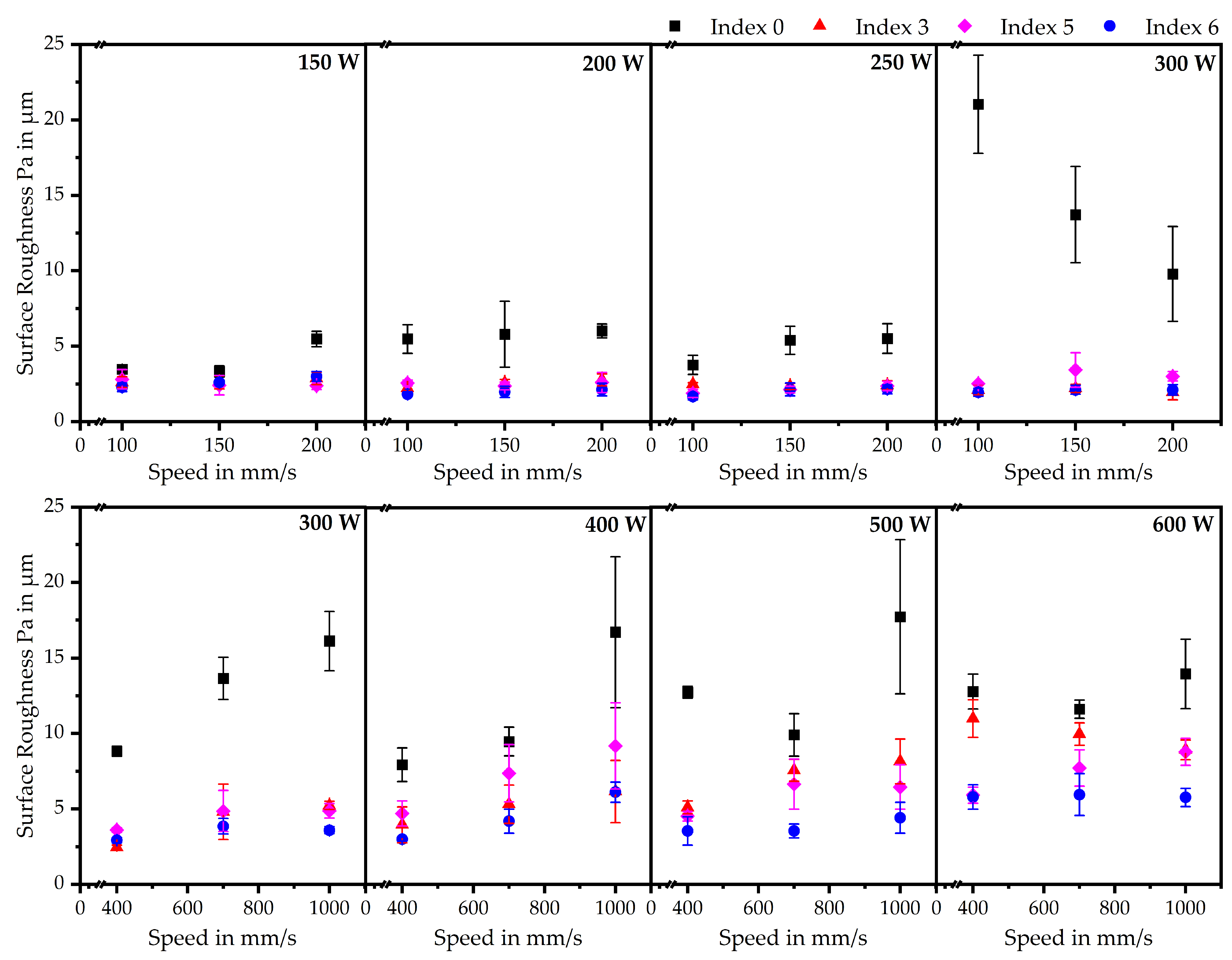
3.3. Surface Roughness

So far, only the cross sections of the weld tracks were investigated regarding their surface quality. However, these results only give a local indication of the influence of beam profiles. Therefore, Figure 10 shows top-down views of the weld tracks for different intensity distributions. The weld tracks for the Gaussian profile show noticeable irregularities for both slow and high scan speeds (red arrows). While the distortions and irregularities at lower velocities are formed due to too much heat input, the higher weld speeds exhibit significant humping. These result from the high weld speed, which leads to insufficient length-to-width rations and matches studies by Yadroitsev et al. [6]. With increasing power distribution to the ring, the melt tracks exhibit fewer defects. While some slight humping can still be seen for Index 3 (orange arrows), Index 5 and Index 6 maintain stable melt pool geometries, and only show slight anomalies for the highest weld speed (black arrows). This can be explained by the higher beam width caused by the spot diameter and intensity distribution, leading to a higher width-to-length ratio, which suppresses humping.
To obtain an overview for all scan tracks, the primary profile P a of the weld track surfaces is depicted in Figure 11. Overall, the Gaussian profile exhibits the largest surface roughness, and the trends for 300 W match the explanation for Figure 10. Larger melt pools result in lower melt pool dynamics, leading to a smoother weld surface. Furthermore, the surface roughness of all beam profiles increases with increasing weld speed, with one notable exception for the Gaussian profile at 300 W beam power. Additionally, the surface roughness constantly increases with increasing weld speeds. This also applies for the point/ring-shaped profiles, as can be further seen in through the anomalies in the top-down views. Another characteristic is that Index 6 has the lowest surface roughness, especially with a stronger increase in scan speeds. The point/ring-shaped profiles exhibit lower surface roughness than the Gaussian profile that was already described. The heat input is more evenly distributed, reducing overheating. Furthermore, the melt pool widens (as shown in Figure 5), increasing the contact area between melt and substrate, which again reduces the need for hump formation. Secondly, the melt pool gets more stable due to the uniform intensity distribution.

4. Conclusions

The aim of this study was to investigate the influence of different beam shapes for the laser-based processing of high-strength aluminium alloys on the basis of single weld tracks. A double-core AFX-1000 laser was used, which is capable of producing various point/ring beam profiles by partitioning the intensity between the core and the ring. Beam shaping is remarked as a feasible method to improve the production of aluminium alloys, which are prone to hot cracking in laser welding applications as well as in PBF-LB. Therefore, the aluminium alloy EN AW-5083 was chosen as a substrate material. Single weld tracks were produced using a test rig consisting of the stationary AFX-1000 laser source, and a small process chamber mounted on an axis for acceleration and deceleration was used. Four different beam profiles were chosen, gradually shifting the intensity from 100 % in the core to a ratio of 10/90 between the core and ring, respectively. The weld tracks were analyzed regarding their melt pool quality and geometry, as well as surface roughness. The main findings of this work are as follows:
  • Beam shaping has influence on the melt pool dimensions. All point/ring profiles exhibit wider melt pools compared to the purely Gaussian beam profile. Furthermore, the width of the Gaussian beam profile is far more dependent on the beam power.
  • The point/ring profiles have surprisingly higher penetration depths than the Gaussian beam for low beam powers. Although the purely Gaussian beam overcomes this effect at higher beam powers, Index 5 exhibits still higher depths than Indices 3 and 5.
  • Shifting the intensity distribution from the core to the ring leads to a significantly wider processing window with more stable melt pools and fewer cracks for high weld speeds.
  • The humping effect is significantly reduced for the point/ring-shaped beam profiles, leading to a smoother surface.
The results of the single weld tracks provide an initial assessment of in-house beam shaping for further use in the laser-based processing of high-strength aluminium alloys. The increased processing window, with fewer hot cracks and the generation of more stable weld tracks over the scan length for point/ring profiles, opens the possibility of achieving higher production rates in the laser welding of EN AW-5083. Therefore, these experiments qualify for an extension to other high-strength aluminium alloys. Furthermore, the geometry and quality of the melt pool shapes imply different thermal conditions during the laser/matter interaction. Since different thermal gradients can affect microstructure evolution, further investigations need to be conducted.
Finally, the results of this work can give a first indication in regard to other laser-based processing methods of high-strength aluminium alloys such as PBF-LB. Since crack-free weld tracks could be produced at high speeds with the point/ring profiles, similar experiments should be carried out using one powder layer. Defect-free single melt tracks could be the starting point for subsequent build jobs of simple geometries. Therefore, the aim should be for a detailed analysis regarding the hot cracking behavior and further improvements of the processability.

Author Contributions

Conceptualization, F.N.; methodology, F.N.; validation, F.N.; formal analysis, F.N.; investigation, F.N.; resources, M.S.; data curation, F.N.; writing—original draft preparation, F.N.; writing—review and editing, D.B., R.R. and M.S.; visualization, F.N.; supervision, M.S.; project administration, M.S.; funding acquisition, M.S. All authors have read and agreed to the published version of the manuscript.

Funding

This research was funded by the German Research Foundation (DFG) for Project-ID 61375930, SFB 814—“Additive Manufacturing” TP A05.

Data Availability Statement

Raw data and material are available upon request.

Acknowledgments

The authors want to thank the German Research Foundation (DFG) for Project-ID 61375930 -SFB 814—“Additive Manufacturing” TP A05. We acknowledge financial support by Deutsche Forschungsgemeinschaft and Friedrich-Alexander Universität Erlangen-Nürnberg within the funding program “Open Access Publication Funding”. The authors gratefully acknowledge the support provided by the Erlangen Graduate School in Advanced Optical Technologies.

Conflicts of Interest

The authors declare no conflict of interest.

References

  1. Deepak, J.R.; Anirudh, R.P.; Sundar, S.S. Applications of lasers in industries and laser welding: A review. Mater. Today Proc. 2023. [Google Scholar] [CrossRef]
  2. Lee, H.; Lim, C.H.J.; Low, M.J.; Tham, N.; Murukeshan, V.M.; Kim, Y.J. Lasers in additive manufacturing: A review. Int. J. Precis. Eng. Manuf.-Green Technol. 2017, 4, 307–322. [Google Scholar] [CrossRef]
  3. Galbusera, F.; Caprio, L.; Previtali, B.; Demir, A.G. The influence of novel beam shapes on melt pool shape and mechanical properties of LPBF produced Al-alloy. J. Manuf. Process. 2023, 85, 1024–1036. [Google Scholar] [CrossRef]
  4. Rudolf, A. Donut worry: How laser powder bed fusion matures dramatically due to ring-shaped beams. Photonics Views 2023, 20, 28–31. [Google Scholar] [CrossRef]
  5. Mills, K.C.M.; Keene, B.J.; Brooks, R.F.; Shirali, A. Marangoni effects in welding. Philos. Trans. R. Soc. London. Ser. Math. Phys. Eng. Sci. 1998, 356, 911–925. [Google Scholar] [CrossRef]
  6. Yadroitsev, I.; Gusarov, A.; Yadroitsava, I.; Smurov, I. Single track formation in selective laser melting of metal powders. J. Mater. Process. Technol. 2010, 210, 1624–1631. [Google Scholar] [CrossRef]
  7. Patschger, A.; Seiler, M.; Bliedtner, J. Influencing factors on humping effect in laser welding with small aspect ratios. J. Laser Appl. 2018, 30, 032409. [Google Scholar] [CrossRef]
  8. Berger, P.; Hügel, H.; Hess, A.; Weber, R.; Graf, T. Understanding of humping based on conservation of volume flow. Phys. Procedia 2011, 12, 232–240. [Google Scholar] [CrossRef]
  9. Messler, R.W., Jr. Principles of Welding: Processes, Physics, Chemistry, and Metallurgy; John Wiley & Sons: Hoboken, NJ, USA, 2008. [Google Scholar]
  10. Metelkova, J.; Kinds, Y.; Kempen, K.; de Formanoir, C.; Witvrouw, A.; Van Hooreweder, B. On the influence of laser defocusing in Selective Laser Melting of 316L. Addit. Manuf. 2018, 23, 161–169. [Google Scholar] [CrossRef]
  11. Paraschiv, A.; Matache, G.; Condruz, M.R.; Frigioescu, T.F.; Ionică, I. The influence of laser defocusing in selective laser melted IN 625. Materials 2021, 14, 3447. [Google Scholar] [CrossRef]
  12. Nie, X.; Chen, Z.; Qi, Y.; Zhang, H.; Zhang, C.; Xiao, Z.; Zhu, H. Effect of defocusing distance on laser powder bed fusion of high strength Al–Cu–Mg–Mn alloy. Virtual Phys. Prototyp. 2022, 15, 325–339. [Google Scholar] [CrossRef]
  13. Sow, M.C.; De Terris, T.; Castelnau, O.; Hamouche, Z.; Coste, F.; Fabbro, R.; Peyre, P. Influence of beam diameter on Laser Powder Bed Fusion (L-PBF) process. Addit. Manuf. 2020, 36, 101532. [Google Scholar] [CrossRef]
  14. Rasch, M.; Roider, C.; Kohl, S.; Strauß, J.; Maurer, N.; Nagulin, K.Y.; Schmidt, M. Shaped laser beam profiles for heat conduction welding of aluminium-copper alloys. Opt. Lasers Eng. 2019, 115, 179–189. [Google Scholar] [CrossRef]
  15. Ayoola, W.A.; Suder, W.J.; Williams, S.W. Effect of beam shape and spatial energy distribution on weld bead geometry in conduction welding. Opt. Laser Technol. 2019, 117, 280–287. [Google Scholar] [CrossRef]
  16. Hansen, K.S.; Kristiansen, M.; Olsen, F.O. Beam shaping to control of weldpool size in width and depth. Phys. Procedia 2014, 56, 467–476. [Google Scholar] [CrossRef]
  17. Hollatz, S.; Hummel, M.; Lach, M.; Olowinsky, A.; Gillner, A.; Häfner, C.; Beckmann, J.; Moosmann, J. Influence of ring-shaped laser beam during welding of AW-5083 and AW-6082. In Proceedings of the High-Power Laser Materials Processing: Applications, Diagnostics, and Systems XII, San Francisco, CA, USA, 15 March 2023; Volume 12414, pp. 80–89. [Google Scholar]
  18. Punzel, E.; Hugger, F.; Dinkelbach, T.; Bürger, A. Influence of power distribution on weld seam quality and geometry in laser beam welding of aluminum alloys. Procedia CIRP 2020, 94, 601–604. [Google Scholar] [CrossRef]
  19. Abadi, S.N.R.; Mi, Y.; Sikström, F.; Ancona, A.; Choquet, I. Effect of shaped laser beam profiles on melt flow dynamics in conduction mode welding. Int. J. Therm. Sci. 2021, 166, 601–604. [Google Scholar]
  20. Wischeropp, T.M.; Tarhini, H.; Emmelmann, C. Influence of laser beam profile on the selective laser melting process of AlSi10Mg. J. Laser Appl. 2020, 32, 022059. [Google Scholar] [CrossRef]
  21. Cloots, M.; Uggowitzer, P.J.; Wegener, K. Investigations on the microstructure and crack formation of IN738LC samples processed by selective laser melting using Gaussian and doughnut profiles. Mater. Des. 2016, 89, 770–784. [Google Scholar] [CrossRef]
  22. Metel, A.S.; Stebulyanin, M.M.; Fedorov, S.V.; Okunkova, A.A. Power density distribution for laser additive manufacturing (SLM): Potential, fundamentals and advanced applications. Technologies 2018, 7, 5. [Google Scholar] [CrossRef]
  23. Shi, R.; Khairallah, S.A.; Roehling, T.T.; Heo, T.W.; McKeown, J.T.; Matthews, M.J. Microstructural control in metal laser powder bed fusion additive manufacturing using laser beam shaping strategy. Acta Mater. 2020, 184, 284–305. [Google Scholar] [CrossRef]
  24. Tumkur, T.U.; Voisin, T.; Shi, R.; Depond, P.J.; Roehling, T.T.; Wu, S.; Crumb, M.F.; Roehling, J.D.; Guss, G.; Khairallah, S.A.; et al. Nondiffractive beam shaping for enhanced optothermal control in metal additive manufacturing. Sci. Adv. 2021, 7, 9358. [Google Scholar] [CrossRef] [PubMed]
  25. Okunkova, A.; Volosova, M.; Peretyagin, P.; Vladimirov, Y.; Zhirnov, I.; Gusarov, A.V. Experimental approbation of selective laser melting of powders by the use of non-Gaussian power density distributions. Phys. Procedia 2014, 56, 48–57. [Google Scholar] [CrossRef]
  26. Okunkova, A.A.; Peretyagin, P.Y.; Podrabinnik, P.A.; Zhirnov, I.V.; Gusarov, A.V. Development of laser beam modulation assets for the process productivity improvement of selective laser melting. Procedia IUTAM, Sci. Adv. 2021, 7, 177–186. [Google Scholar] [CrossRef]
  27. Grigoriev, S.N.; Gusarov, A.V.; Metel, A.S.; Tarasova, T.V.; Volosova, M.A.; Okunkova, A.A.; Gusev, A.S. Beam shaping in laser powder bed fusion: Péclet number and dynamic simulation. Metals 2018, 12, 722. [Google Scholar] [CrossRef]
  28. Burger, L.; Litvin, I.; Ngcobo, S.; Forbes, A. Implementation of a spatial light modulator for intracavity beam shaping. J. Opt. 2014, 17, 015604. [Google Scholar] [CrossRef]
  29. Kliner, D.A.V.; O’Dea, B.; Lugoa, J.; Farrow, R.L.; Hawke, R.; Hodges, A.; Stephens, R.; Foley, B.; Almonte, K.; Kehoe, B.; et al. High-productivity Laser Powder-Bed Fusion tools enabled by AFX fiber lasers with rapidly tunable beam quality. In Proceedings of the 12th CIRP Conference on Photonic Technologies, Fürth, Germany, 4–8 September 2022. [Google Scholar]
  30. Kliner, D.A.; Farrow, R.L.; Lugo, J.; O’Dea, B.; Hawke, R.; Victor, B.; Gross, K.; Hodges, A.; Brown, A.; Pruyn, J.; et al. Advanced metal processing enabled by fiber lasers with tunable beam properties. In Proceedings of the Fiber Lasers XIX: Technology and Systems SPIE Lase, San Francisco, CA, USA, 22 January–28 February 2022; p. 11981. [Google Scholar]
  31. Grünewald, J.; Gehringer, F.; Schmöller, M.; Wudy, K. Influence of ring-shaped beam profiles on process stability and productivity in laser-based powder bed fusion of AISI 316L. Metals 2021, 11, 1989. [Google Scholar] [CrossRef]
  32. Lantzsch, T.; Heussen, D.; Praetzsch, N.; Haefner, C. Evaluation of productivity scaling approaches for laser powder bed fusion of nickel-base alloy 625. In Proceedings of the High-Power Laser Materials Processing: Applications, Diagnostics, and Systems XI, San Francisco, CA, USA, 20–24 February 2022; p. 11994. [Google Scholar]
  33. Rothfelder, R.; Huber, F.; Schmidt, M. Influence of beam shape on spatter formation during PBF-LB/M of Ti6Al4V and tungsten powder. Procedia CIRP 2022, 111, 14–17. [Google Scholar] [CrossRef]
  34. Aboulkhair, N.T.; Simonelli, M.; Parry, L.; Ashcroft, I.; Tuck, C.; Hague, R. 3D printing of Aluminium alloys: Additive Manufacturing of Aluminium alloys using selective laser melting. Progress in materials science. Prog. Mater. Sci. 2019, 106, 100578. [Google Scholar] [CrossRef]
  35. Mauduit, A.; Pillot, S.; Gransac, H. Study of the suitability of aluminum alloys for additive manufacturing by laser powder bed fusion. UPB Sci. Bull. Ser. B Chem. Mater. Sci. 2017, 79, 219–238. [Google Scholar]
  36. Sánchez-Amaya, J.M.; Delgado, T.; González-Rovira, L.; Botana, F.J. Laser welding of aluminium alloys 5083 and 6082 under conduction regime. Appl. Surf. Sci. 2009, 255, 9512–9521. [Google Scholar] [CrossRef]
  37. Okon, P.; Dearden, G.; Watkins, K.; Sharp, M.; French, P. Laser welding of aluminium alloy 5083. Int. Congr. Appl. Lasers Electro-Opt. 2002, 2002, 158364. [Google Scholar]
  38. Hu, Z.; Nie, X.; Qi, Y.; Zhang, H.; Zhu, H. Cracking criterion for high strength Al–Cu alloys fabricated by selective laser melting. Addit. Manuf. 2021, 37, 101709. [Google Scholar] [CrossRef]
  39. Ostermann, F. Anwendungstechnologie Aluminium; Springer: Berlin/Heidelberg, Germany, 2014. [Google Scholar]
  40. Stopyra, W.; Gruber, K.; Smolina, I.; Kurzynowski, T.; Kuźnicka, B. Laser powder bed fusion of AA7075 alloy: Influence of process parameters on porosity and hot cracking. Additive Manufacturing. Addit. Manuf. 2020, 35, 101270. [Google Scholar] [CrossRef]
  41. Böhm, C.; Werz, M.; Weihe, S. Practical approach to eliminate solidification cracks by supplementing AlMg4. 5Mn0. 7 with AlSi10Mg powder in laser powder bed fusion. Materials 2022, 15, 572. [Google Scholar] [CrossRef] [PubMed]
  42. Maina, M.R.; Okamoto, Y.; Okada, A.; Närhi, M.; Kangastupa, J.; Vihinen, J. High surface quality welding of aluminum using adjustable ring-mode fiber laser. J. Mater. Process. Technol. 2018, 258, 180–188. [Google Scholar] [CrossRef]
  43. DIN German Institute for Standardization. DIN EN 573-3:2019-10, Aluminium and Aluminium Alloys-Chemical Composition and form of Wrought Products—Part 3: Chemical Composition and Form of Products, German version EN 573-3:2019; Beuth Verlag GmbH: Berlin, Germany, 2019. [Google Scholar]
  44. DIN German Institute for Standardization. DIN EN ISO 4288:1998-04, Surface Texture: Profile Method-Rules and Procedures for the Assessment of Surface Texture (ISO 4288:1996), German version EN ISO 4288:1997; Beuth Verlag GmbH: Berlin, Germany, 1997. [Google Scholar]
  45. Patel, S.; Chen, H.; Vlasea, M.; Zou, Y. The influence of beam focus during laser powder bed fusion of a high reflectivity aluminium alloy—AlSi10Mg. Additive Manufacturing. Addit. Manuf. 2022, 59, 103112. [Google Scholar]
  46. Tang, C.; Le, K.Q.; Wong, C.H. Physics of humping formation in laser powder bed fusion. Int. J. Heat Mass Transf. 2020, 149, 119172. [Google Scholar] [CrossRef]
  47. Nedal Aluminium: ALLOY DATA SHEET EN-AW 5083 [AlMg4.5Mn0.7]. Available online: https://www.nedal.com/wp-content/uploads/2017/11/Nedal-alloy-Datasheet-EN-AW-5083.pdf (accessed on 26 April 2023).
  48. Nedal Aluminium: ALLOY DATA SHEET EN AW-6082 [AlSi1MgMn]. Available online: https://www.nedal.com/wp-content/uploads/2016/11/Nedal-alloy-Datasheet-EN-AW-6082.pdf (accessed on 26 April 2023).
  49. Bonifaz, E.A.; Mena, A.S. The Cooling Rate and Residual Stresses in an AISI 310 Laser Weld: A Meso-Scale Approach. Crystals 2022, 12, 502. [Google Scholar] [CrossRef]
Figure 1. Test rig and process chamber used for the experiments.
Jmmp 07 00093 g001
Figure 2. Intensity distribution of the beam profiles used in the experiments for a laser power of 200 W.
Jmmp 07 00093 g002
Figure 3. Layout of the parameter combinations on the specimen.
Jmmp 07 00093 g003
Figure 4. Classification of the melt pool quality and geometry.
Jmmp 07 00093 g004
Figure 5. Melt pool width for the different beam profiles and parameter sets.
Jmmp 07 00093 g005
Figure 6. Melt pool depth for the different beam profiles and parameter sets.
Jmmp 07 00093 g006
Figure 7. Comparison of the melt pool geometries for the different indices and beam powers (150 W) and (300 W) at low welding speeds (150 mm/s).
Jmmp 07 00093 g007
Figure 8. Comparison of the melt pools for the different indices at 1000 mm/s and 300 W and 600 W beam power, respectively.
Jmmp 07 00093 g008
Figure 9. Processing window for the single weld tracks according to the melt pool cross sections.
Jmmp 07 00093 g009
Figure 10. Comparison of the surface morphology for the different indices and rising weld speed at constant beam power of 300 W.
Jmmp 07 00093 g010
Figure 11. Comparison of the surface roughness characterized by the primary profile Pa for the different indices and parameter sets.
Jmmp 07 00093 g011
Table 1. Chemical composition of EN AW-5083 according to DIN EN 573-3 [43].
AlSiFeCuMnMg
EN AW-5083 (wt. %)bal.≤0.4≤0.4≤0.10.4–1.04.0–4.9
Table 2. Power distribution of the AFX laser and the measured spot diameter for a laser power of 200 W.
IndexPower Ratio Core/RingSpot DiameterM 2 θ
0100/0113 µm1.4116.82 mrad
170/30163 µm2.2518.64 mrad
260/40227 µm2.6915.99 mrad
350/50267 µm3.2216.32 mrad
440/60292 µm4.7722.10 mrad
520/80326 µm3.8215.84 mrad
610/90334 µm3.9616.03 mrad
Table 3. Parameters used for the experiments.
Beam Power P L (W)Weld Speed v S (mm/s)Index
Parameter set 1150, 200, 250, 300100, 150, 200,0, 3, 5, 6
Parameter set 2300, 400, 500, 600400, 700, 10000, 3, 5, 6
Disclaimer/Publisher’s Note: The statements, opinions and data contained in all publications are solely those of the individual author(s) and contributor(s) and not of MDPI and/or the editor(s). MDPI and/or the editor(s) disclaim responsibility for any injury to people or property resulting from any ideas, methods, instructions or products referred to in the content.

