1. Introduction
Electrification is nowadays seen as one of the key strategies used to address global challenges related to environmental degradation and climate change. However, the replacement of a fossil-fuel-based economy with renewable energy sources, combined with the growing shift to electric vehicles and 5G broadband, requires an expansion of electric grids to accommodate energy demands more than ever before.
Busbars are electric grid components responsible for the transmission and distribution of energy in low-voltage, high-current applications. They are made from copper and/or aluminum strips and their use is generally preferred to the use of wires and cables because of their easiness to install and maintain, compactness, and safety [
1]. In the case of electric vehicles, for example, busbars are responsible for supplying energy to electric motors, electric power steering systems and AC/DC converters, among other components.
The assembly of individual busbars into electric grids involving multiple connections is expected to cause minor disturbances in the electric current flow (i.e., to provide low electrical resistance) and to be trustworthy throughout lifetime. The fabrication of electric conductive connections (hereafter referred to as ‘busbar joints’) is therefore of paramount importance to the overall reliability and performance of the electric grids.
Manufacturing processes used to connect individual busbars can be classified into two main categories: (i) welding and (ii) mechanical joining [
2]. Resistance spot welding and laser welding are among the most utilized welding processes, but their use is restricted by distortion and residual stresses arising from the heating–cooling cycles. They also suffer from weldability difficulties when the busbars are made from dissimilar materials (typically copper and aluminum) with different thermomechanical properties [
3].
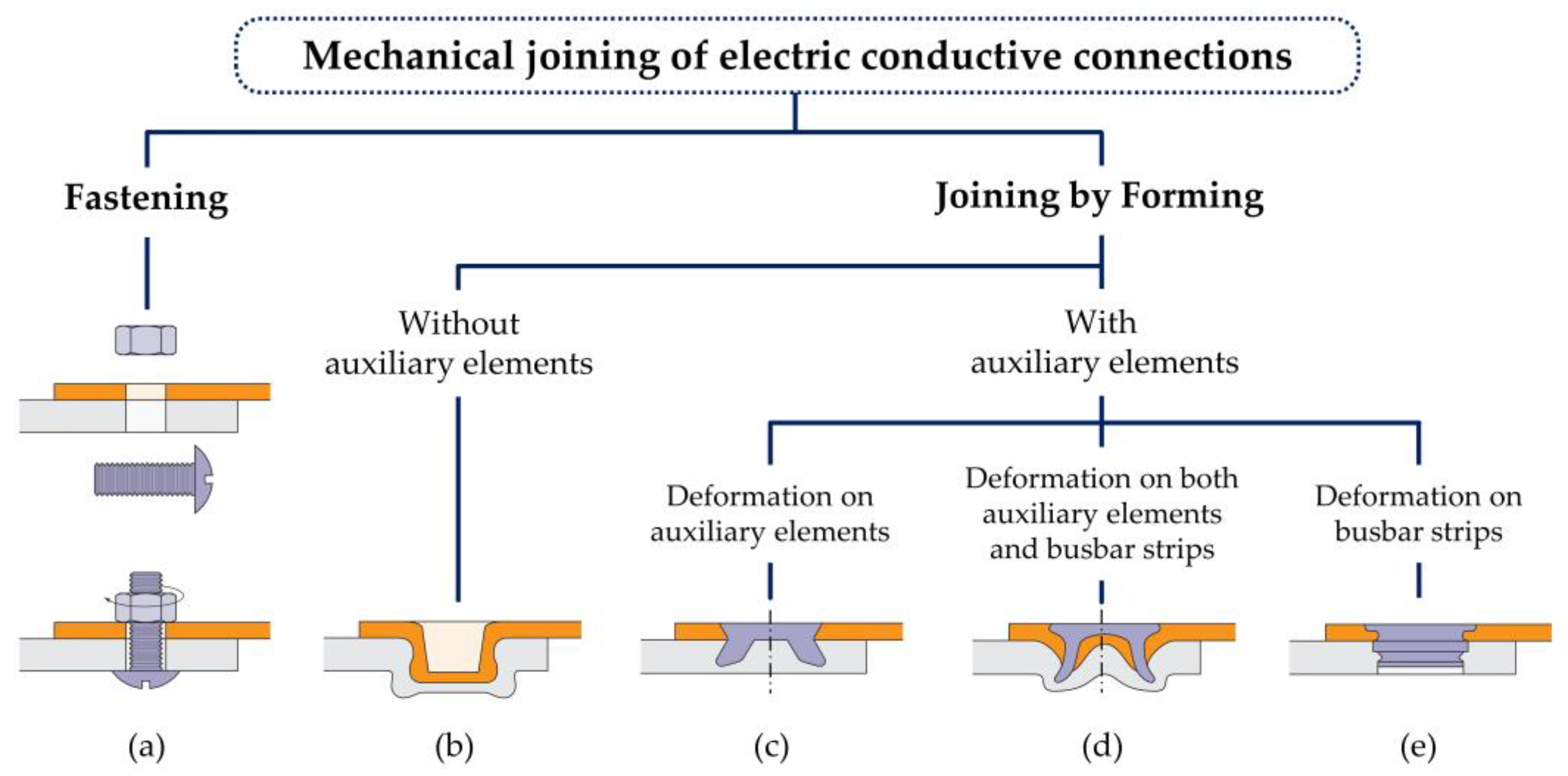
Mechanical joining comprises a much wider range of processes that can be sub-divided into two groups: (i) fastening and (ii) joining by forming [
4] (
Figure 1). Fastening makes use of auxiliary elements, such as bolts or conventional rivets. Bolted joints (
Figure 1a) are mostly used to connect individual busbars because of their easiness in assembly and disassembly. Still, their use can be limited by bolt-head and nut protrusions above and below the busbar surfaces, and by unintentional self-loosening and non-uniform contact pressures on the overlapped busbar surfaces. The last two problems give rise to disturbances in the electric current flow that increase the electrical resistance of the joints.
Joining by forming includes all the processes in which plastic deformation is employed to produce electric conductive connections by means of form-closed and/or force-closed mechanisms. Two main subgroups are considered to yield a distinction between joining by the forming processes with no use or use of auxiliary elements [
5]. Clinching (
Figure 1b), for example, is a process belonging to the first subgroup (without auxiliary elements) [
6] and involves the plastic deformation of both individual busbars to produce combined form-closed/force-closed electric-conductive joints [
7].
Injection lap riveting [
8] (
Figure 1c), self-pierce riveting [
9] (
Figure 1d), and self-clinching [
10] (
Figure 1e) belong to the second subgroup (with auxiliary elements). They join by forming processes in which plastic deformation occurs mainly in the auxiliary elements, in both auxiliary elements and busbars, and mainly in the busbars, respectively. Schematic drawings illustrating the three different types of processes are enclosed in
Figure 1.
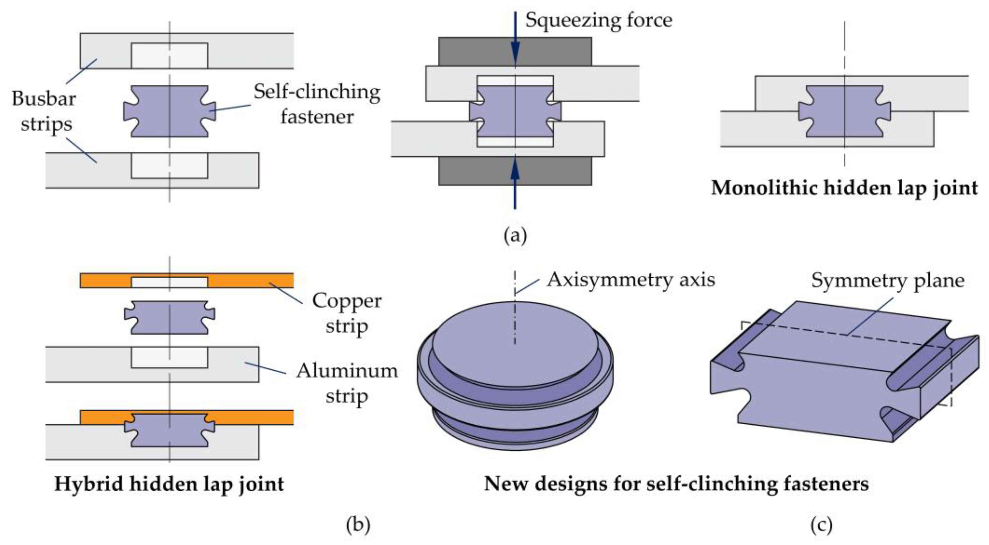
The process variant and joint to be addressed in this paper belong to the ‘self-clinching’ subgroup (
Figure 1e), which needs holes with adequate dimensions to be drilled or punched into the overlapped busbars before applying a squeezing force to the fasteners (or, in some cases, to the busbars) and obtaining a form-closed/force-closed lap joint. In particular, this paper focuses on a new type of self-clinching fastener, recently developed by the authors [
10], that yields the production hidden lap joints (
Figure 2a).
However, unlike the previous work that was aimed at structural applications and made use of steel fasteners, the authors now focus on new design features of the joints that enhance and improve electric current flow and electrical resistance at different service temperatures [
11]. The new design features consist of (i) the connection of copper and aluminum busbars with different thicknesses by means of self-clinching fasteners made from the same (or similar) materials of the busbars (
Figure 2b) and (ii) the utilization of longitudinal symmetric self-clinching fasteners (
Figure 2c).
The first design feature is of paramount importance for electric-conductive connections because the assembly of copper and aluminum busbars requires a combination of different thicknesses to ensure equivalent entry and exit conductance. In addition, they also require the use of copper or aluminum fasteners instead of steel to minimize disturbances in the electric current flow.
The second design feature represents a novelty in joining by forming because connections with auxiliary elements are predominantly rotation symmetric. Non-rotation symmetric joints reported in the literature, such as micro-shear clinching [
12], sheet-bulk compression [
13] or rectangular clinching [
14], make no use of auxiliary elements; therefore, they do not belong to the group of joining by forming processes where self-clinching belongs (
Figure 1). The main goal to be achieved with the second design feature is to replicate the resistance-seam-welding contact conditions, in which continuous joints are also hidden inside the regions where the two busbars overlap.
The fulfilment of the new design features yields an extension of the self-clinching hidden-lap-joint concept to electric grids. This is the main objective of this investigation, which is supported by a combination of numerical and experimental work that makes use of rotational and longitudinal symmetric self-clinching fasteners. Conventional bolted joints are used for comparison purposes.
2. Materials and Methods
The work was carried out in unit cells representing the electric-conductive connections. Both monolithic joints constructed solely from aluminum busbars and hybrid joints constructed from copper and aluminum busbars were considered to reflect the current trend in replacing copper with aluminum in all or parts of the electric grids. The research methodology involved the mechanical and thermo-electrical characterization of the busbar materials, followed by the fabrication and testing of the new joints.
2.1. Mechanical Characterization of the Materials
C11000 electrolytic copper strips (99.9% Cu) and two types of aluminum strips (AA1050-H111 with 99.5% Al and the AA6082-T6 aluminum-magnesium-silicon alloy) were utilized in multiple busbar arrangements. Self-clinching fasteners made from a high-strength AA7075-T6 aluminum alloy, with zinc as the primary alloying element, were used instead of conventional steel fasteners to minimize disturbances in the electric current flow.
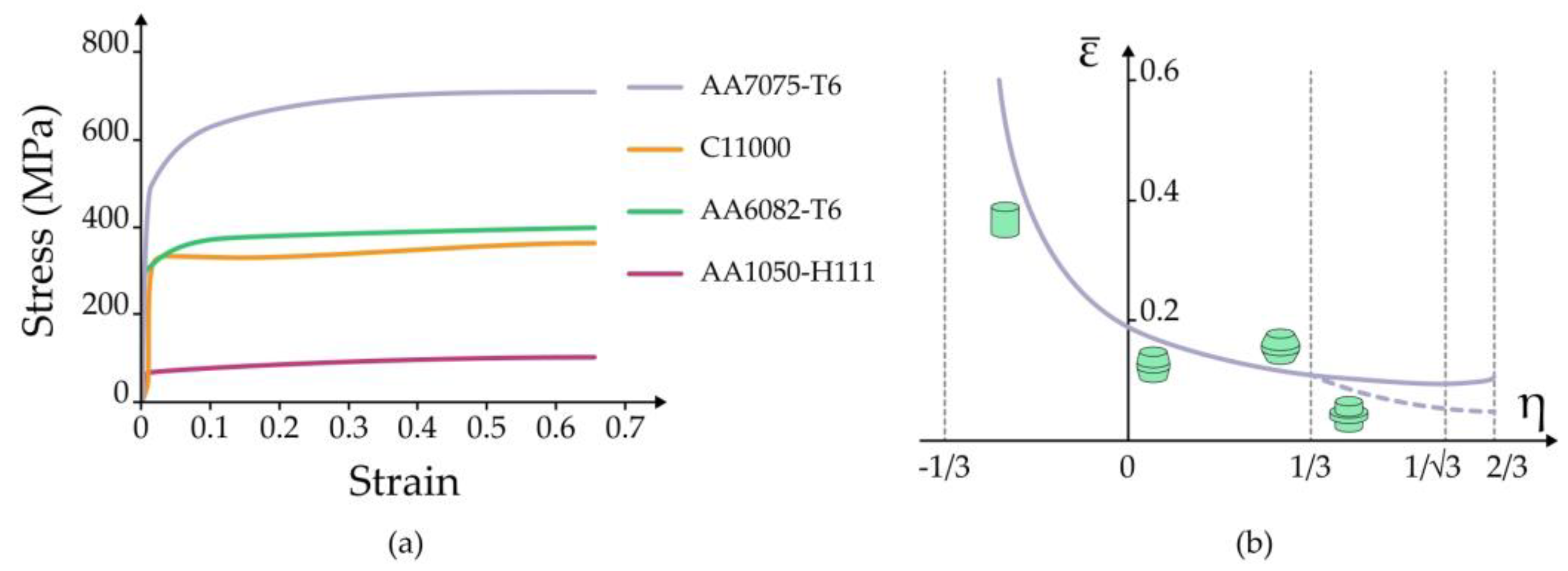
The mechanical behavior of the busbar materials was characterized by means of tensile tests at the ambient temperature in specimens that were extracted from the strips and tested in accordance with ASTM standards E8/E8 M [
15]. The tests were performed in an Instron 4507 universal testing machine and the resulting flow stresses, after extrapolation, are plotted in
Figure 3a.
As seen from the different flow stress evolutions, the rationale behind the utilization of two different types of aluminum alloys is seen in the analysis of how dependent on the busbar material strength the self-clinched joints are.
The flow stress of the fasteners’ material was determined by means of compression tests at the ambient temperature. The tests were made in cylindrical specimens of 20 mm in height and 20 mm in diameter that were machined from the AA7075-T6 aluminum rods used to produce the fasteners. The flow stress of the AA7075-T6 aluminum alloy is also included in
Figure 3a.
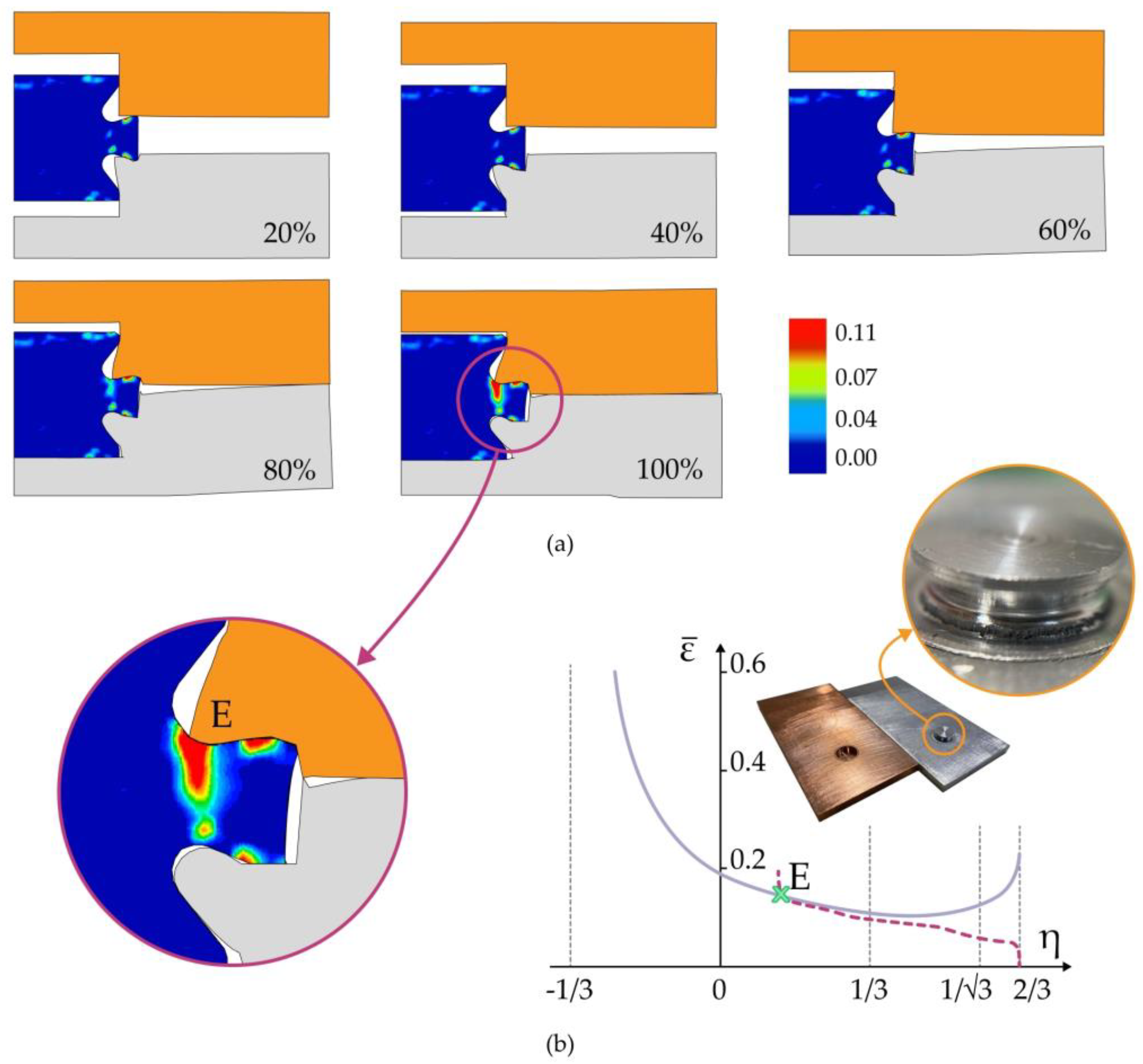
The solid and dashed lines in
Figure 3b represent the fracture-forming limits of the AA7075-T6 aluminum alloy in the effective strain
vs. stress triaxiality
space. These lines were constructed from experimental values retrieved from conventional bulk formability tests, previously carried out by the authors [
16], in cylindrical, tapered, and flanged specimens. The reason for including this information in the paper was related to the failure of self-clinching fasteners, which is addressed later in the article.
2.2. Thermo-Electrical Characterization of the Materials
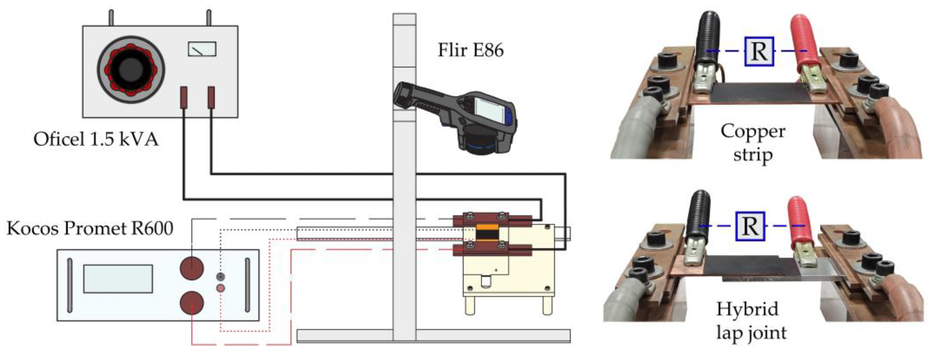
The electrical resistivity of the busbar and fastener materials was determined from the electrical resistance of test specimens using a four-point probe technique [
17]. The technique is based on Ohm’s law and requires measurements of the voltage drop
V by means of two probes spaced a distance apart (100 mm) and connected to a micro-ohmmeter KoCoS PROMET R600 that supplied an electric current of 600 A for approximately 2 s.
Figure 4 provides a scheme of the experimental setup in which an AC transformer (OFICEL 1.5 kVA) was used to pre-heat the specimens by Joule effect to a maximum temperature
°C (at the center). An infrared camera (FLIR E86) was employed to monitor and register the temperature. Further details on the heating, cooling, and measurement procedures are provided in [
11].
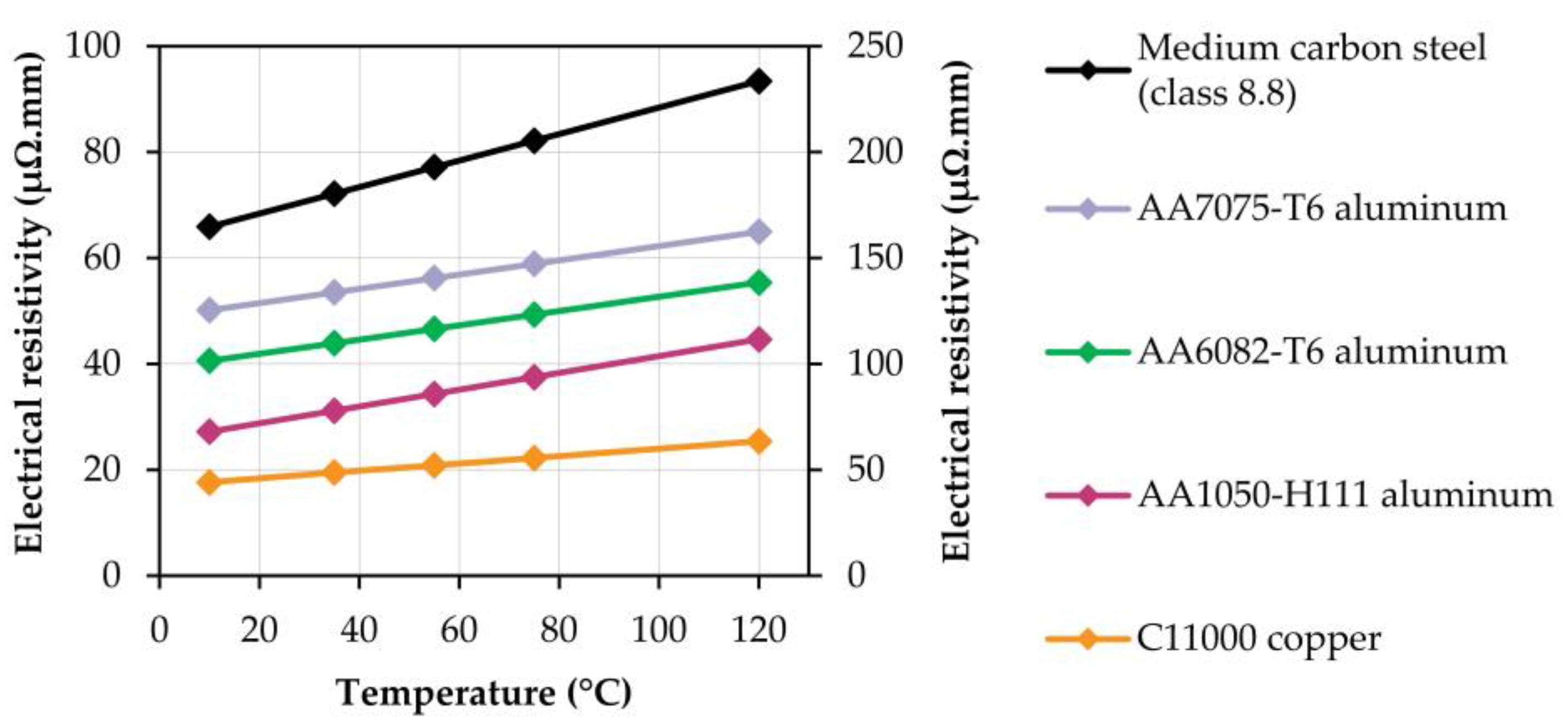
Voltage drop measurements were taken in the cooling stage after switching off the AC transformer, within the temperature range of 105 °C to 20 °C, according to the IEEE standard for metal-clad switchgears [
18]. The evolution of the electrical resistivity with temperature for the busbar and fastener materials is given in
Figure 5.
The evolution of the electric resistivity with temperature for the medium carbon steel of the bolts and nuts used in conventional (reference) bolted joints was retrieved from the literature [
19] and revealed much higher values than the remaining materials.
2.3. Fabrication and Testing of the Self-Clinched Joints
The experimental work on self-clinched joints made use of busbar strips with a length of 100 mm in length, width of 50 mm, and thickness of 2 mm or 5 mm.
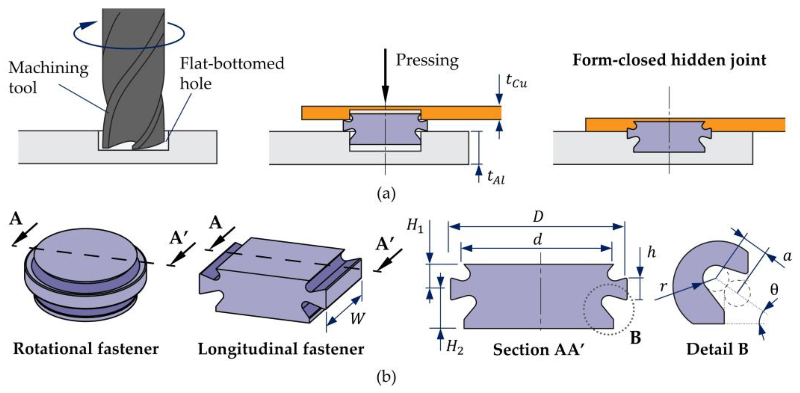
Figure 6a summarizes the fabrication route to obtain a self-clinched hybrid joint from copper and aluminum strips with
mm and
mm thickness, respectively. The thickness ratio
was close to the theoretical ratio of approximately 2.3 that ensures equal conductance in the busbars considering the electric resistivities of copper and aluminum [
1] (
Figure 5).
As shown, flat-bottomed (counterbore) holes or shallow pockets with different depths were first machined in adjacent regions of the busbars. Then, rotational or longitudinal symmetric self-clinching fasteners with a cross-section similar to that shown in
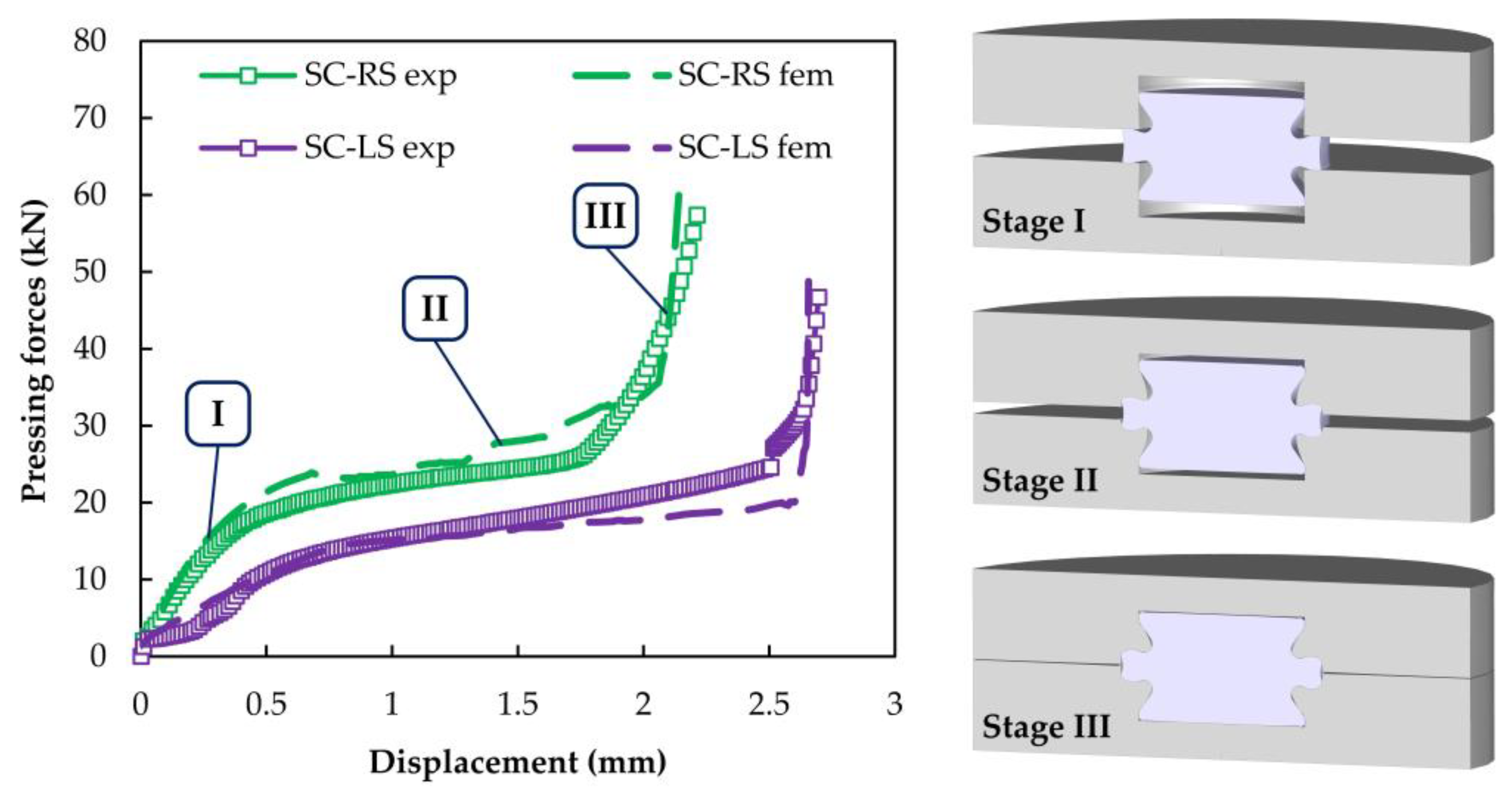
Figure 6b were placed in position. Finally, the busbars were pressed against each other to plastically deform the material around the fasteners and create permanent form-closed hidden joints. Pressing was carried out in an Instron SATEC 1200 kN hydraulic testing machine at the ambient temperature.
The experimental and numerical development was associated with the new design features involved in the testing of monolithic and hybrid joints made from similar and dissimilar materials, with equal or different strip thicknesses, and with the use of rotational and longitudinal symmetric high-strength aluminum fasteners with an electrical resistivity similar to that of the aluminum strips. The plan of experiments is summarized in
Table 1.
The utilization of two types of aluminum strips with significant differences in strength compared to copper strips was intended to provide an answer to the question of how dependent the new self-clinched joints are on the material’s relative strength.
The geometry of the self-clinching fasteners (refer to
Figure 6b) was based on those used in a previous work of the authors [
10] to obtain monolithic joints made from AA5754-H111 aluminum strips with a thickness of 5 mm and rotational symmetric AISI 316L stainless-steel fasteners. The dimensions of the rotational symmetric fasteners are given in
Table 2 and include the following: (i) the outer diameter
D; (ii) the semi-heights
H1 and
H2; (iii) the upper and lower head diameters
d; (iv) the flange height
h; (v) the fillet radius
r; (vi) the depth
a; and (vii) the inclination
θ of the fastener annular grooves. Variations in semi-height
H1 are necessary to accommodate the connection of busbars with different thicknesses.
In the case of longitudinal symmetric fasteners, symbols D and d denote the fastener outer and head lengths, respectively, while W denotes the fastener width. The values of these dimensions were adjusted to ensure equal volume to that of the rotational symmetric fasteners for comparison purposes.
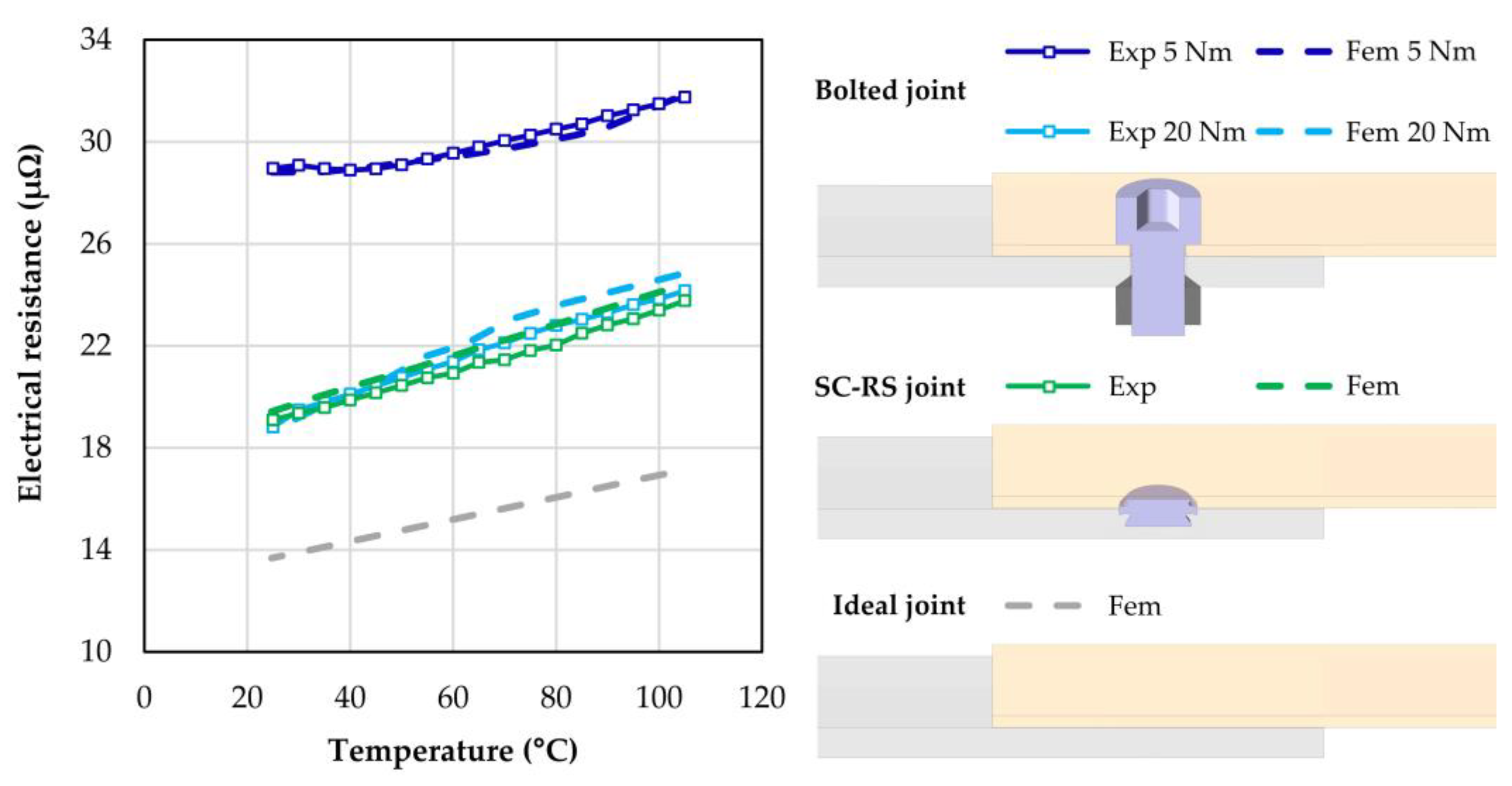
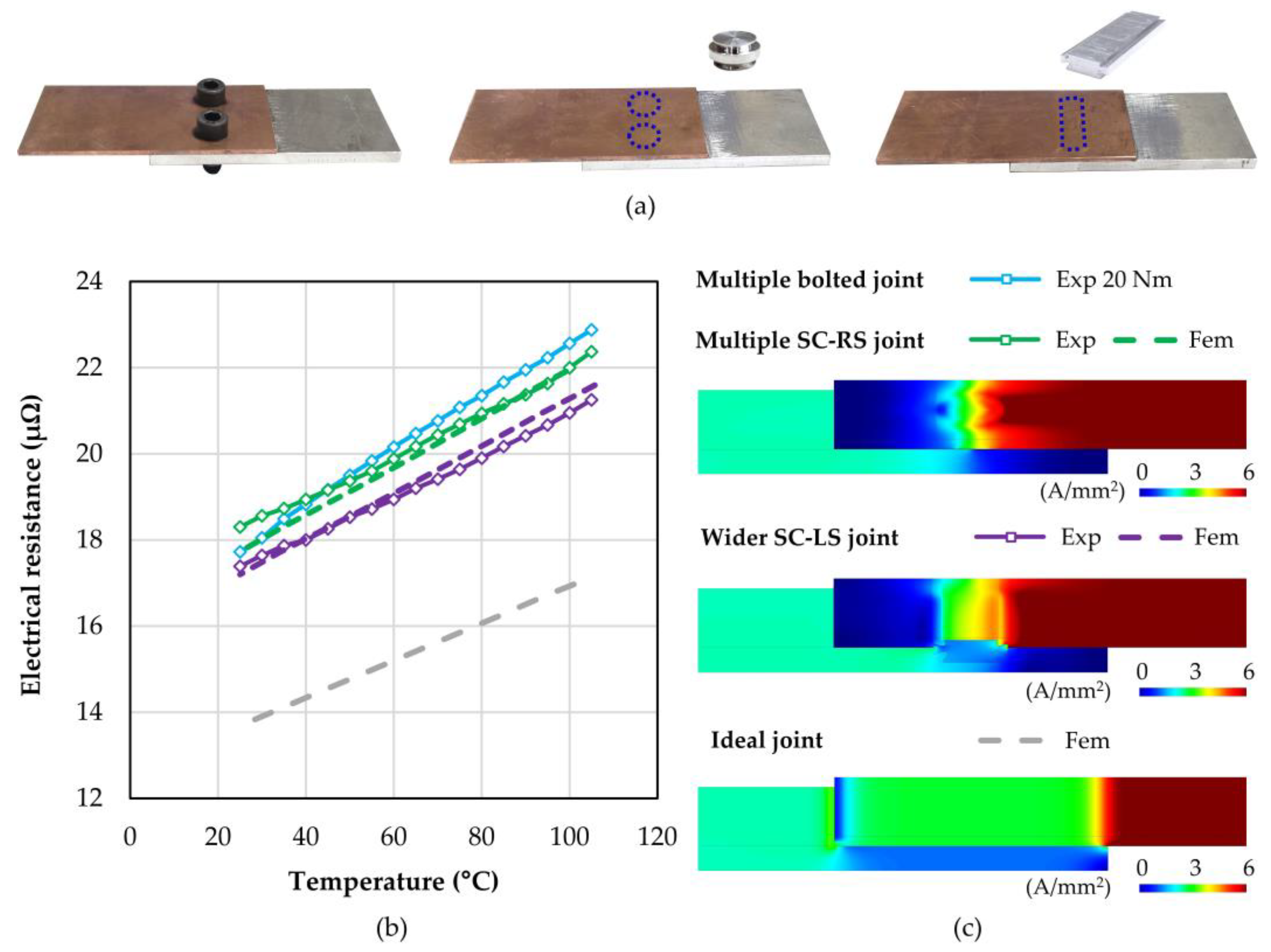
The electrical performance of the self-clinched joints with the new design features was evaluated by measuring the evolution of the electrical resistance with the temperature in the experimental setup that was previously shown in
Section 2.2. Values were compared against those of conventional M8 bolted joints subjected to tightening torques of 5 Nm and 20 Nm [
20].
2.4. Finite Element Analysis
Numerical simulation of the fabrication and testing of the new self-clinched joints made use of the in-house thermo-electro-mechanical finite element computer program i-form. The program was developed by the authors [
21] and couples an extended version of the quasi-static flow formulation that includes elastic effects with electric potential and heat transfer equations. The weak forms of the governing mechanical (1), electrical (2), and thermal (3) equations for a continuous body with a control volume
V bounded by a closed surface
S, consisting of a region
St where tractions
ti are applied and a region
Sq where the heat flux
qn containing the heat dissipated by convection and radiation is defined, are given by,
The primary unknowns of each governing equation are the velocity , the electric potential , and the temperature . The remaining symbols in Equations (1) to (3) are the deviatoric Cauchy stress , the rate of deformation , the volumetric rate of deformation , the penalty function K, the thermal conductivity k, the volumetric heat capacity , and the fraction of plastic work converted into heat.
Different modelling strategies were used depending on the objectives to be attained. The fabrication of the self-clinched joints only used the mechanical engine of the finite element computer program in conjunction with axisymmetric or plane strain cross-sectional models, depending on whether rotational or longitudinal symmetric fasteners were employed.
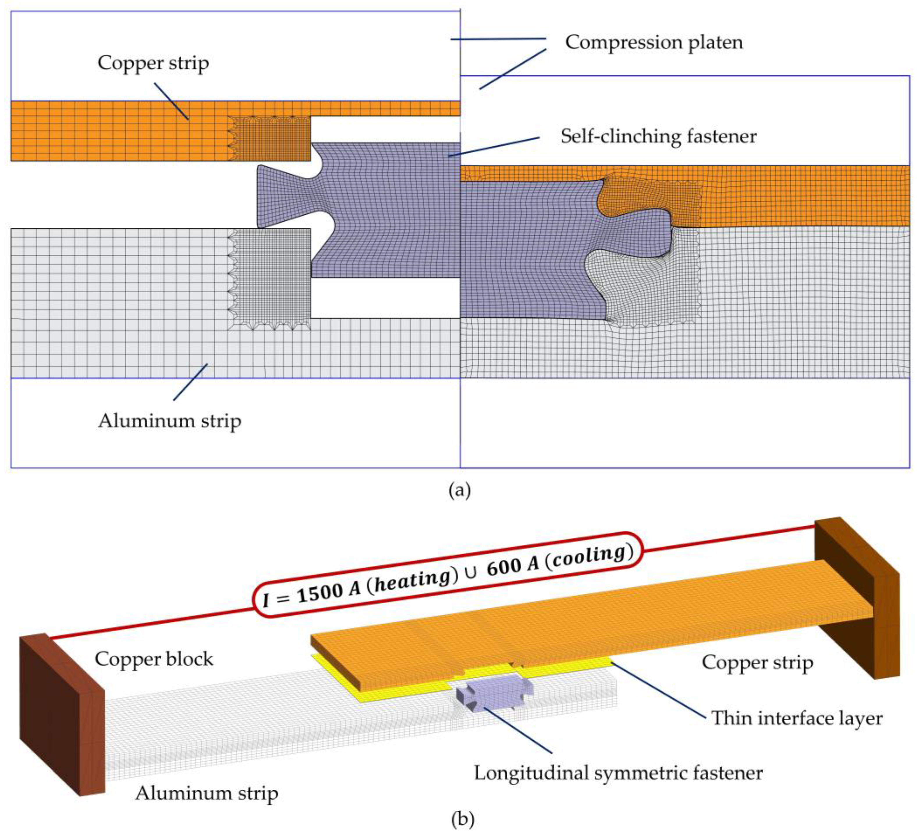
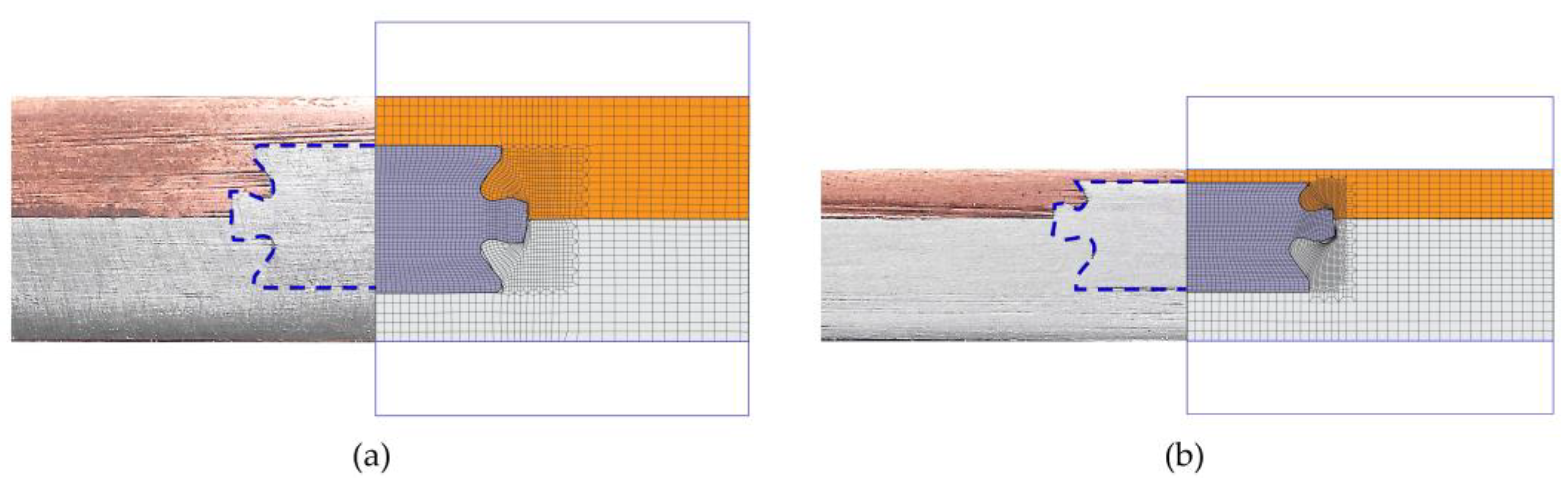
Figure 7a shows a plane strain model with approximately 5000 quadrilateral elements at the beginning and end of the joining process of a self-clinched (hidden) hybrid joint. As seen, both fastener and busbar strips were modelled as deformable objects, whereas the upper and lower squeezing (compression) platens were modelled as rigid objects and their cross-sections were discretized by means of linear contact elements.
The thermo-electric performance of the joints required the discretization of the unit cells by means of three-dimensional models built upon approximately 70,000 hexahedral elements. Symmetric conditions yielded the use of half-width size models, in which the busbars and fasteners were treated as deformable objects and the copper blocks utilized to fix the specimens and supply the electric current of 1500 A of the AC transformer during the pre-heating stage were treated as rigid objects (
Figure 7b).
A thin interface layer with a thickness of 0.05 mm was included in the model to account for the influence of surface roughness and oxide films along the busbar overlapped region [
22].
The modelling of the thermo-electrical response of the joints consisted of simulating their cooling by conduction, convection, and radiation after switching off the AC transformer and supplying an electrical current of 600 A for approximately 2 s each time the temperature dropped by approximately 10 °C, until reaching the ambient temperature (20 °C).
In the case of bolted joints, the thermo-electrical response was coupled with mechanical analysis to replicate the tightening torque put on the bolts. This was conducted through the application of an equivalent tension force at the bolts’ end.
4. Conclusions
Self-clinching fasteners with various design features can be successfully utilized to fabricate reliable busbar hybrid joints with low electrical resistance, made from dissimilar materials (e.g., copper and aluminum) with different strip thicknesses, for energy distribution systems.
Self-clinched joints are lighter and more compact than conventional bolted joints and provide values of electrical resistance that are 11% smaller (in average) due to the replacement of the steel bolts and nuts by aluminum fasteners with much smaller electric resistivity. The electrical resistance of the self-clinched hybrid joints increased by approximately 26% when the service temperature was raised from 20 °C to 105 °C.
Differences in strength between busbar materials must be kept small. This is necessary to prevent near-rigid object behaviors and the cracking of the fasteners during self-clinching, as well as the degradation of the electrical performance of the joints during heating–cooling service cycles.
Wider longitudinal symmetric fasteners are a good alternative to bolted and self-clinched joints with multiple bolts or rotational symmetric fasteners due to their ability to provide continuous lap joints with better electrical performance and no increase in weight.


 ,
, 


