Article

Process-Integrated Lubrication in Sheet Metal Forming

1
Institute of Product Development, Leibniz University Hannover, An der Universität 1, 30823 Garbsen, Germany
2
Institute of Forming Technology and Machines, Leibniz University Hannover, An der Universität 2, 30823 Garbsen, Germany
*
Author to whom correspondence should be addressed.
J. Manuf. Mater. Process. 2022, 6(5), 121; https://doi.org/10.3390/jmmp6050121
Submission received: 29 August 2022 / Revised: 30 September 2022 / Accepted: 11 October 2022 / Published: 14 October 2022
(This article belongs to the Special Issue Advances in Material Forming)

Abstract

:
The deep-drawability of a sheet metal blank is strongly influenced by the tribological conditions prevailing in a deep-drawing process. Therefore, new methods to influence the tribology represent an important research topic. In this work, the application of a process-integrated lubrication in a deep-drawing process is investigated. Most promising geometries of the lubrication channels and outlet openings are first identified by means of numerical simulation at the example of a demonstrator process. Cylindrical test specimens with the specified channel geometries are additively manufactured and installed in a strip drawing test stand. Additive manufacturing enables the possibility of manufacturing complex channel geometries which cannot be manufactured by conventional methods. A hydraulic metering device for conveying lubricant is connected to the cylindrical test specimens. Thus, hydraulically lubricated strip drawing tests are performed. The tests are evaluated according to the force curves and the fluid mechanical buildup of pressure cushion. The performance of process-integrated lubrication is thus analyzed and evaluated. By means of a coupled forming and SPH simulation, the lubrication channels could be optimally designed. From the practical tests, it could be achieved that the drawing force decreases up to 27% with pressure cushion build up. In this research, a hydraulic lubrication in the area of highest contact normal stresses is the most optimal process parameter regarding friction reduction.

1. Introduction

With increasing demands on the quality, variety of shapes and complexity of deep-drawn components and simultaneous price reductions due to strong competition, the need for innovative solutions and process variants for deep-drawing is high. Therefore, special processes such as hydromechanical deep-drawing or multi-stage tools are increasingly used for complex shapes or high degrees of forming [1,2]. The deep-drawability of a workpiece is strongly influenced by the tribological conditions prevailing in the process [3,4]. These are of particular importance for components with high total draw ratios. Such drawn parts are often formed in multi-stage tools in several steps to avoid failure during the drawing process [5]. This allows higher overall drawing ratios to be achieved, but is also accompanied by an increase in cycle time, the number of tools required and more complex process control [5]. Optimization of the tribological conditions during deep-drawing with respect to the reduction in friction lowers the number of necessary drawing steps and extends the process limits [6,7]. Such optimization often requires additional lubrication of the sheet for an improved tribological system [8]. In the course of this issue, Hoffmann et al. developed a deep-drawing tool with the possibility to lubricate the blank during forming [9]. For this purpose, a multi-part tool with integrated lubricant supply and removal systems was used. Furthermore, Sekita et al. published a new concept for high-pressure lubrication during deep-drawing [10]. Based on this concept, Klöpsch developed a tool for deep-drawing of rotationally symmetric geometries by means of hydrostatic pressure lubrication at the drawing edge radius [11]. The results showed a significant reduction in the required punch force, which was accompanied by an extension of the forming limits. The further development and optimization of the conventional deep-drawing process shows promising economic and technical advantages [11]. In order to realize hydrostatic pressure lubrication, sometimes complex channel geometries may be necessary in forming tools. These channels are difficult to manufacture with conventional production methods [12]. Additive manufacturing enables a new way to produce forming tools with integrated lubrication channels. Previous projects about process-integrated lubrication did not deal with the geometry optimization of the lubrication channels, which without an optimization, due to the many internal channels, reduce the strength of the tool. On the other hand, such optimization in terms of the number, geometry, course, arrangement, position and angle of the openings can improve the lubrication process and the surface quality of the drawn part and thus lead to an expansion of the process limits. Additive manufacturing offers the possibility to realize maximum geometric complexity in the production of channel and tool geometries [13,14,15,16]. Furthermore, additive manufacturing is also characterized by a high degree of functional integration [12,17]. In addition to reducing the number of parts, local effects such as thermal, electrical, magnetic, damping and lubrication are increasingly integrated into components [13,18,19,20,21,22,23]. As a result of the improved component performance, the costs related to the entire product life cycle can also be saved [24]. For these reasons, additive manufacturing is already being used successfully in the field of rapid tooling [13,14]. Complex additively manufactured channel geometries for process-integrated lubrication in sheet metal forming are therefore researched in this work. First, a numerical based geometry design study for the lubrication channels is carried out on an exemplary forming process. Subsequently, the performance of the most promising channel geometries is investigated in actively hydraulically lubricated strip drawing tests.

2. Materials and Methods

Initially, a realization of lubrication channels in a tool die is considered at an example of a deep-drawing process for the production of a round cup. For this purpose, a forming simulation is carried out to identify the areas of the highest tool loads during forming (Section 2.1). In these areas, the outlets for lubrication channels are provided.
Subsequently, a development environment for the design of the lubrication channels is set up in Section 2.2. The main part of the development environment is the numerical simulation, with which the characteristics of a lubrication cushion between the die and the semi-finished products can be analyzed and evaluated depending on the geometric parameters of the lubrication channels. The most promising geometries are identified numerically and additively manufactured as test specimens for strip drawing tests. Hydraulically lubricated strip drawing tests are performed to analyze the performance of the lubrication channels (Section 2.3).

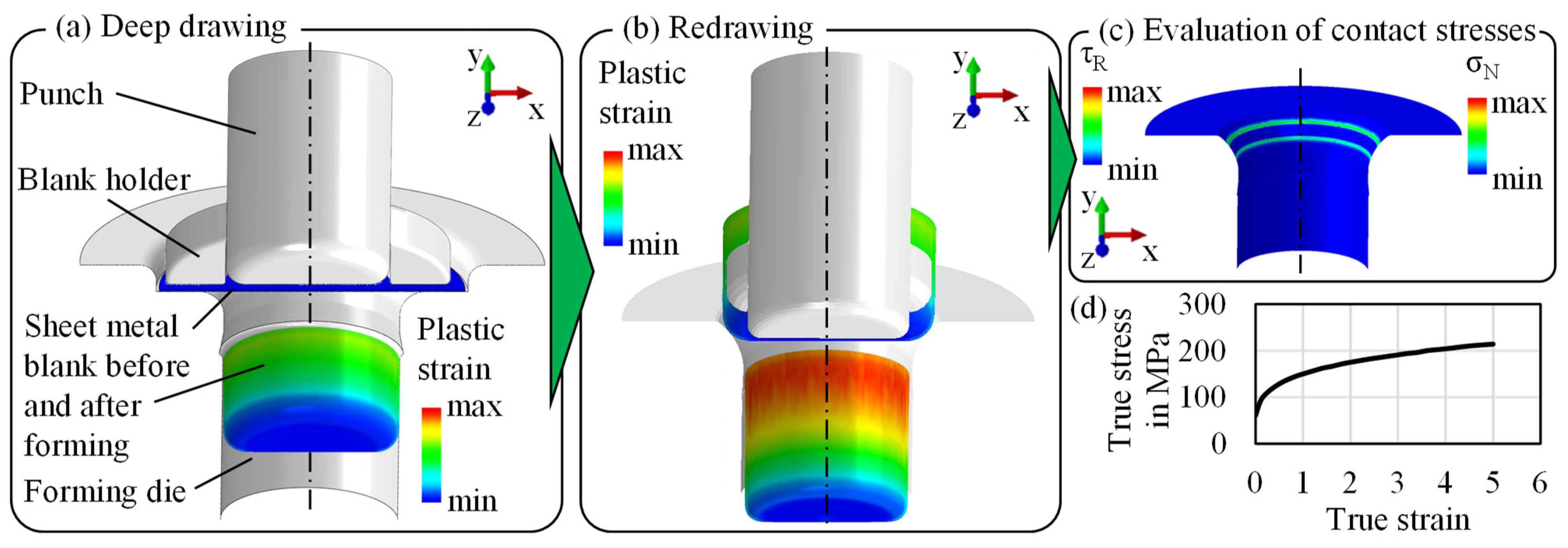
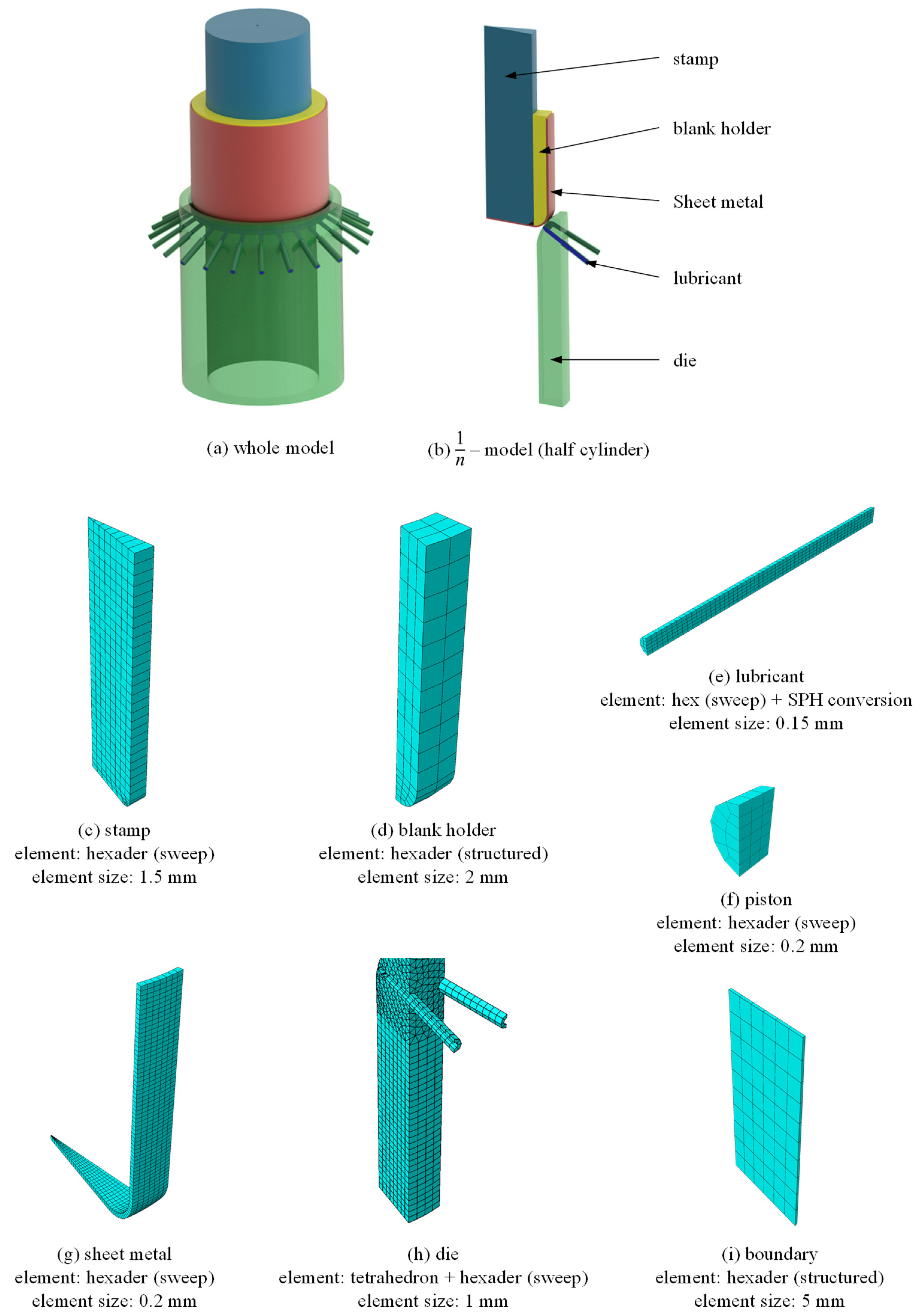
2.1. Mechanical Simulation

A demonstrator process in which a cylindrical cup is produced in two deep-drawing steps is considered for the design of the lubrication channels for a real application case. For this purpose, the positions of the highest contact stresses must initially be identified in order to determine the outlet positions. For an optimal effect of the process-integrated lubrication system, the outlets were intended to be in the area of the highest contact stresses on the surface of the forming die to reduce the frictional load on the surface of the die as well as the workpiece. The considered deep-drawing process is investigated numerically by means of the finite element (FE) method. The aim is to identify the optimal positions of the oil outlets in the second forming stage, as the initial oil layer of the blank is damaged in the first stage. For this purpose, a simulation model of the two-stage forming process was set up in Abaqus. In the first stage, the sheet metal blank is clamped by a blank holder and subsequently deep-drawn into a forming die by a cylindrical punch. The tool setup is shown in Figure 1a. It should be noted that the tool is manufactured by means of laser powder bed fusion, followed by a heat treatment (hardening) and machining. This gives the tool a hardness of 57 HRC and a surface roughness of Rz < 1 µm.
To reduce the computational time, only 1/12 of the process was modelled and symmetry boundary conditions were defined. The tools are modelled as ideal rigid bodies and meshed with shell elements with an element edge length of 0.5 mm. The punch moves at a speed of 10 mm/s for a stroke of 24 mm, so that the blank is completely drawn into the die. For the contact between the tools and the sheet metal, “surface-to-surface-contact” is defined with a friction coefficient of 0.15, which was determined in a previous parameter study. The holding force is modelled using a force-time curve with a linear relationship according to a spring rate of 22.23 N/mm. The sheet metal blank, which has a diameter of 50 mm and a thickness of 0.42 mm, is meshed with quad elements with an element edge length of 0.3 mm. For the sheet material, an elastic-plastic material model of Al 99.8 is defined with a Young’s modulus E of 70 GPa and a Poisson’s ratio υ of 0.35. The flow curve, which is depicted in Figure 1d, is taken from literature [25]. A mass scaling factor of 100 was applied, to reduce the computational time. It was ensured, that the kinetic energy of the model did not exceed 5% of the total energy, which is recommended in the Abaqus documentation. Furthermore, it was ensured, that the mass scaling factor had no significant influence on the forming force or the contact stresses.
After simulating the first forming stage of the demonstrator process, the geometry of the deep drawn cup is transferred to the simulation model of the second forming stage for a redrawing process. The corresponding result variables are also transferred to take the work hardening of the material into account. The tool design of the second stage, shown in Figure 1b, consists of a punch, a forming die and a cup holder. Similarly to the first drawing step, the punch moves at a speed of 10 mm/s for a stroke of 30 mm, so that the cup is completely drawn in. The contact is also defined as “surface-to-surface contact”. The cup holder is fixed and serves solely to hold the cup in its position during forming. In order to evaluate the maximum contact stresses at the drawing edge of the die, the die meshed using shell elements with different element edge length varying between 0.3, 0.5 and 0.7 mm.

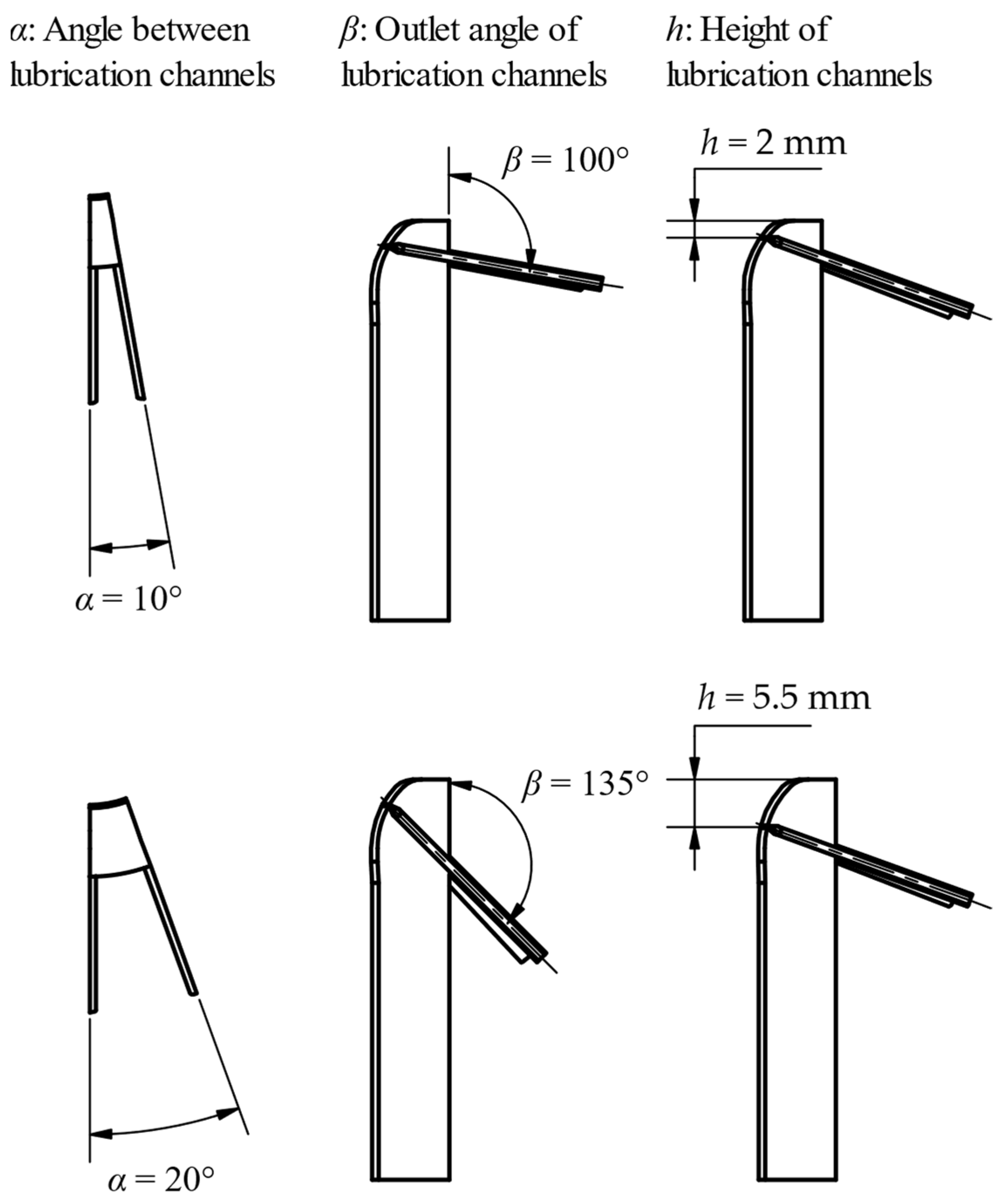
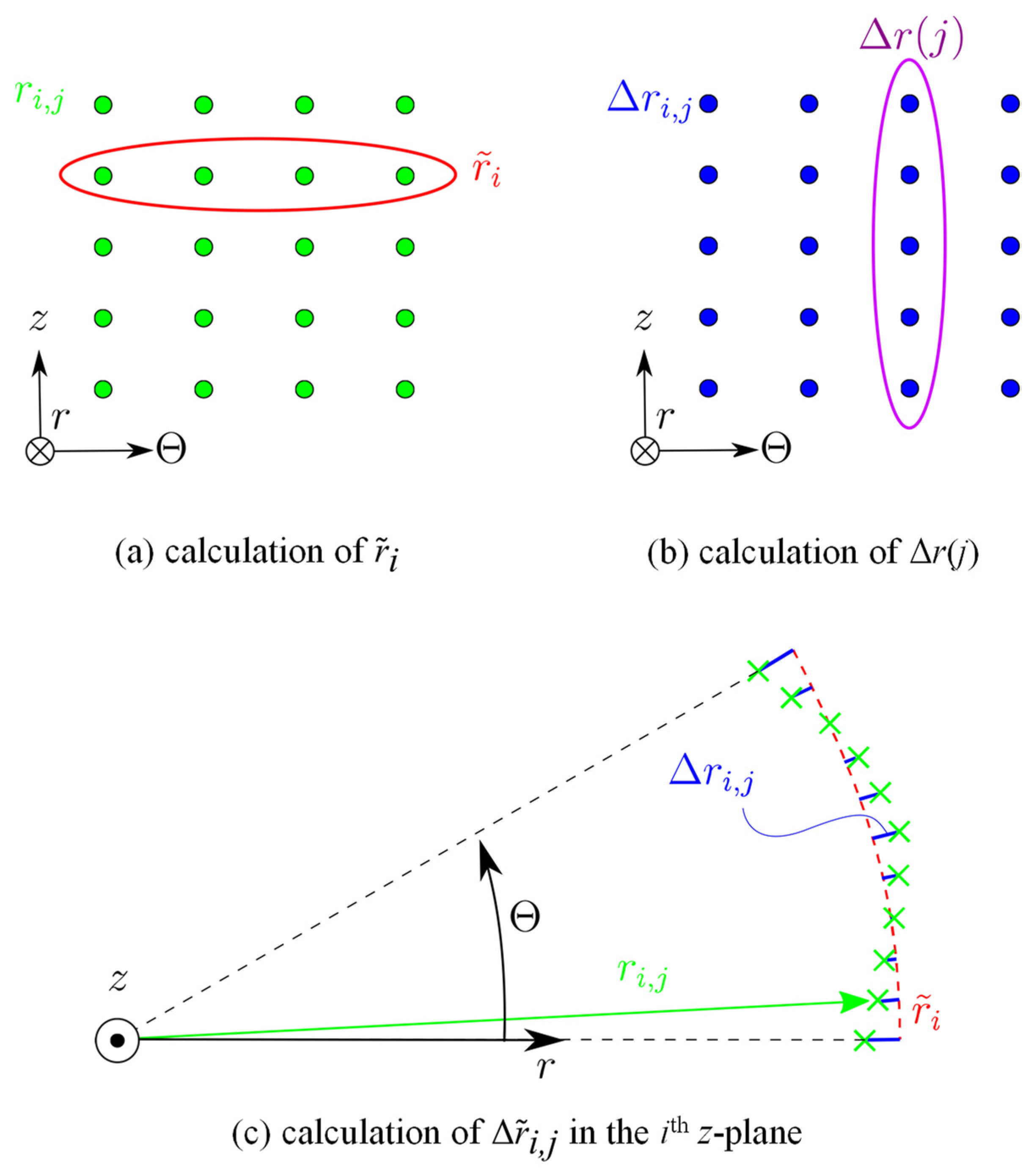
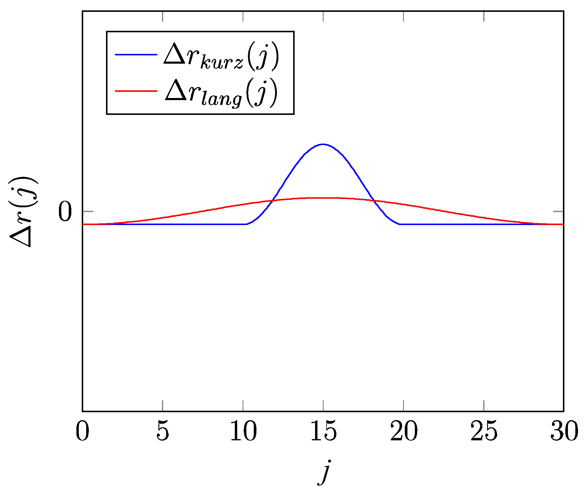
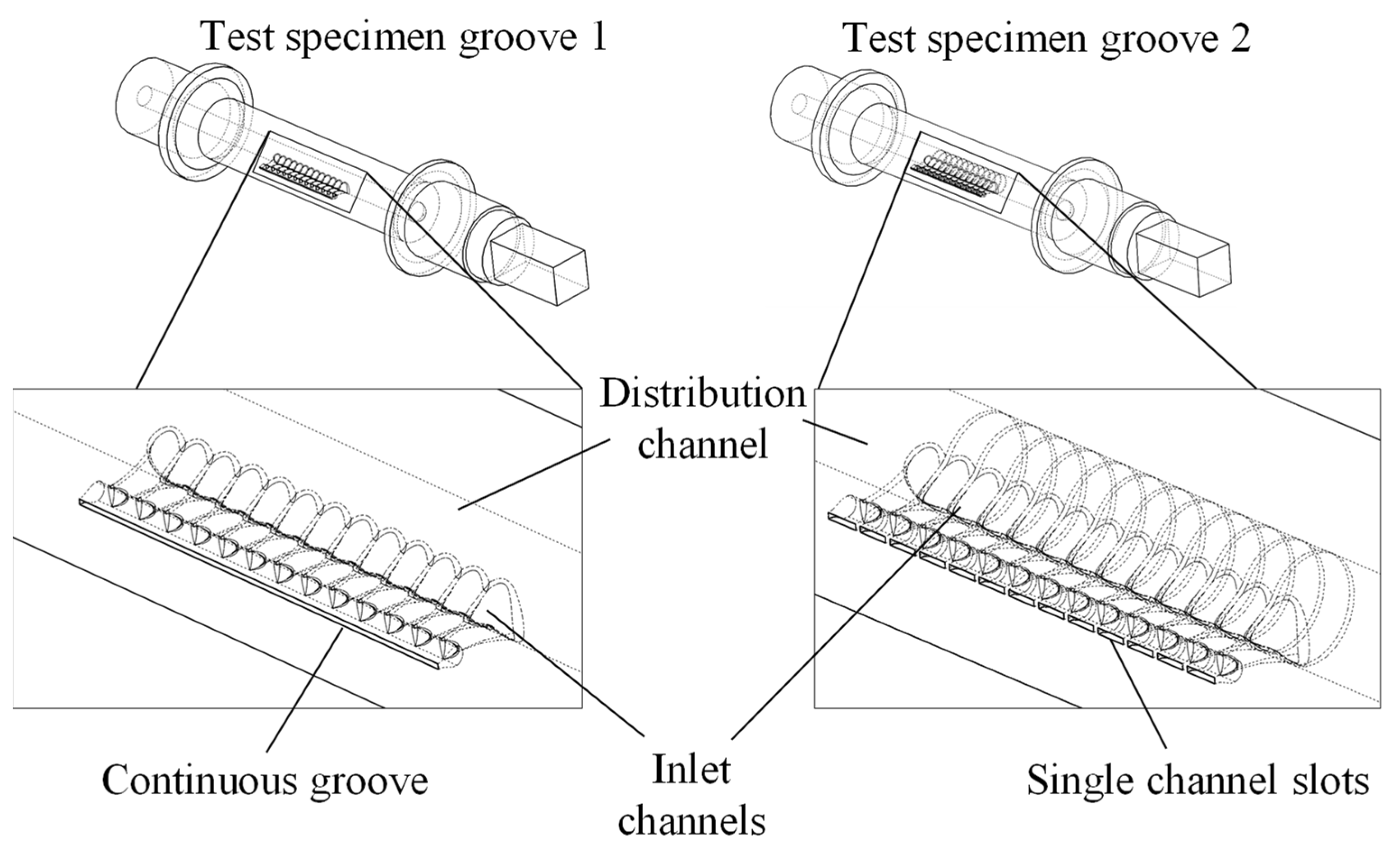
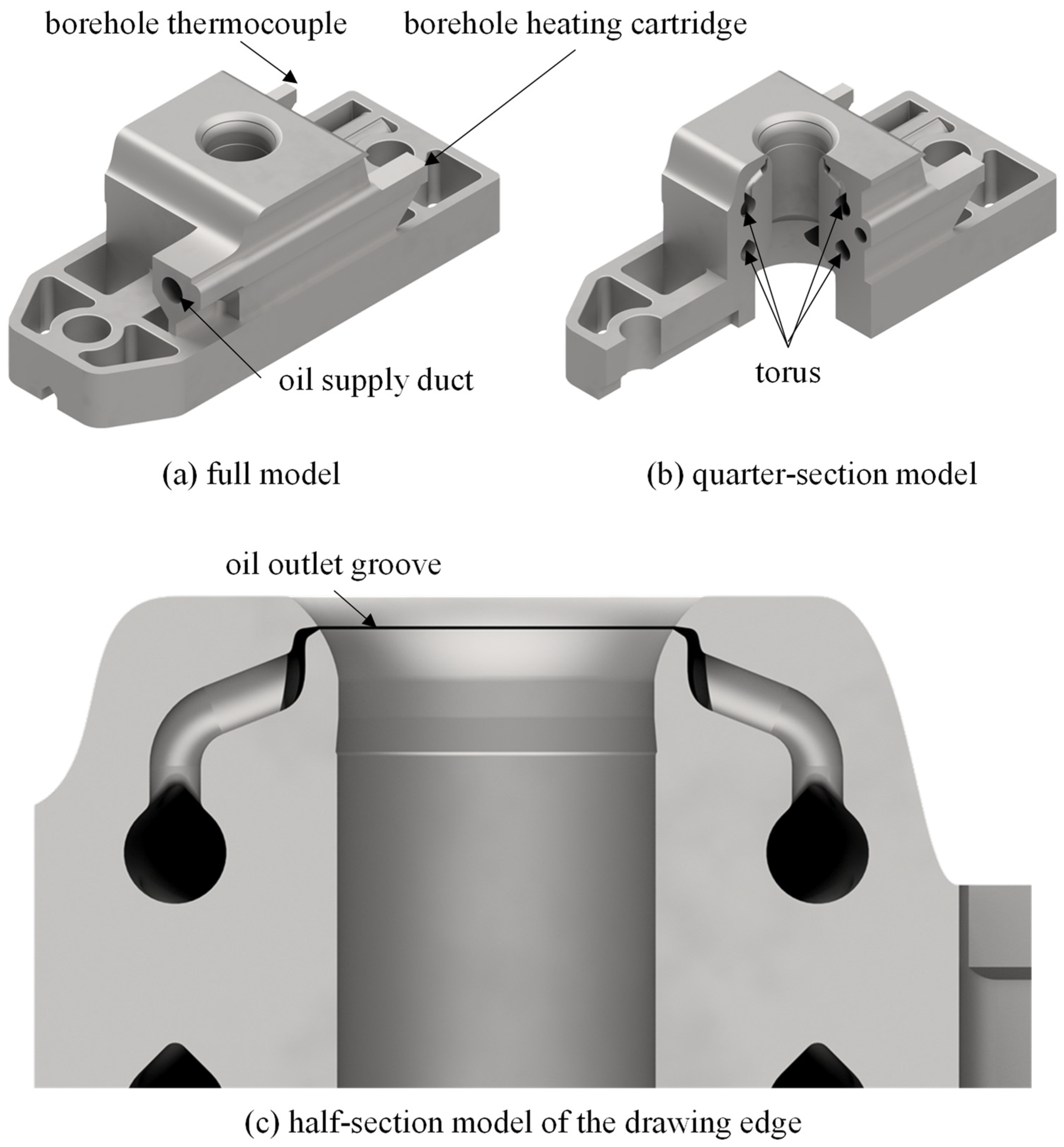
2.2. Design of the Lubrication Channels

In addition to the numerical identification of the mechanical tool loads, a fluid mechanical investigation of the lubrication pad build up between the tool and the semi-finished product is to be carried out. For this purpose, the geometric parameters of the channel geometry of the tool die to be manufactured additively will be varied and analyzed with regard to their effects on the lubrication pad build up. For this purpose, a development environment is set up, which can be used to carry out an automated parameter study on the relevant influencing parameters. In order to be able to simulate both the forming and the lubrication, a coupled forming and flow simulation is implemented in the development environment. For this purpose, the various approaches to flow simulation are described below.

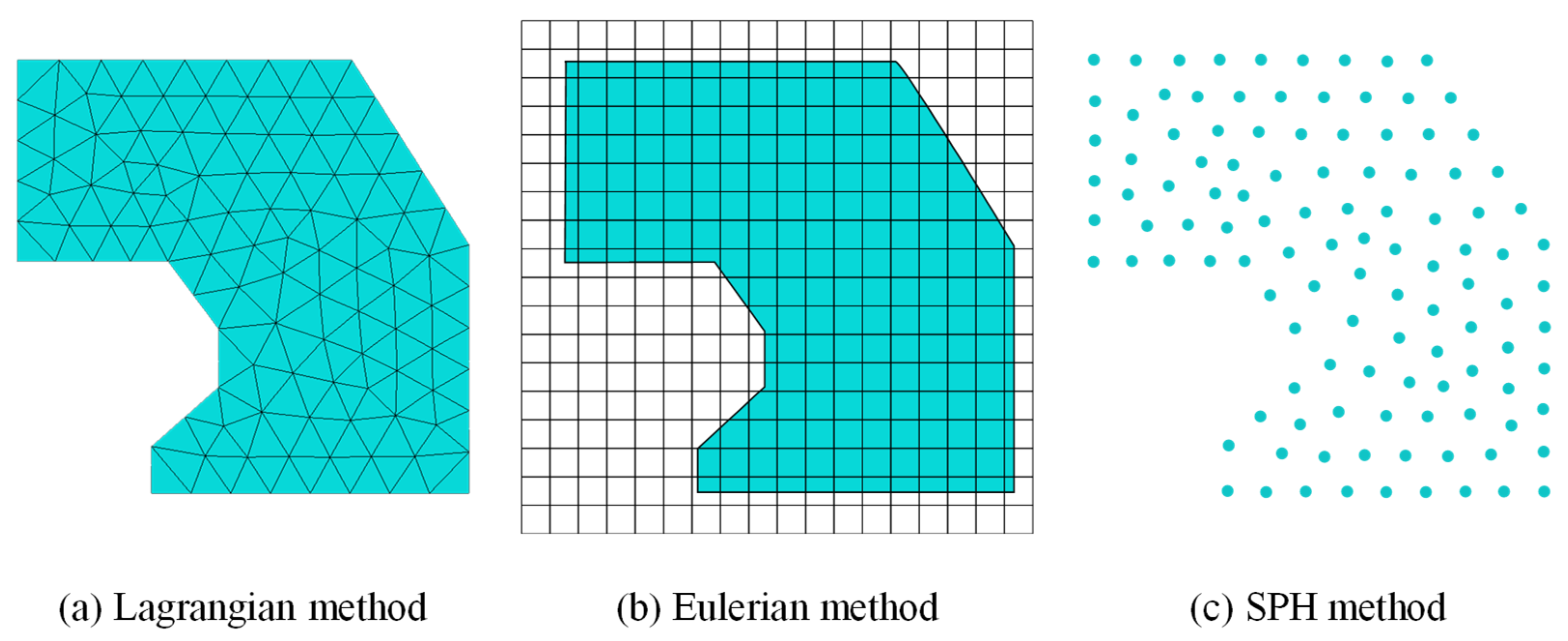
2.2.1. Approaches to Flow Simulation

Oil lubrication can be simulated with the help of CFD simulations [26]. In the first step, a suitable simulation approach for the numerical representation of the process-integrated lubrication must be selected. The Lagrangian method, the Eulerian method and the SPH method are available for this purpose (see Figure 2).
In the Lagrangian method (see Figure 2a), the material and the mesh are fixed to each other. In the case of mesh-based methods, a large deformation leads to an excessive distortion of the elements, which makes a calculation and thus a successful simulation impossible [27]. Especially in the case of large deformations of a fluid or in the case of deforming cavities into which a fluid penetrates, methods that mesh the fluid are no longer suitable [28]. In this case, numerical instabilities can arise due to the strong distortions of the mesh or due to the shifting of boundary conditions [29]. This is particularly relevant for oil lubrication in forming tools, which flows in cavities and splits into small droplets that are no longer connected.
Instead, mesh-free methods such as coupled Euler–Lagrange simulation (CEL simulation) and smoothed particle hydrodynamics (SPH) are more suitable [27,28,29]. In the Eulerian method (see Figure 2b), the material is moved through a fixed mesh. Here, it is not the movement of the individual nodes that is considered, but the mass, momentum and energy flow through the mesh elements. The disadvantage of this method is that individual material points are difficult to track over time. Similarly, complex and irregular geometries are difficult to represent. In contrast to the Lagrangian approach, however, strong deformations of the material can be processed. The coupled Euler–Lagrange simulation makes it possible to use both approaches in one simulation. Through an interface, information from different elements can be exchanged in the course of the simulation. For example, solids with low deformation can be defined as Lagrangian elements and fluids as Eulerian elements [27].
In contrast to the methods presented above, the smoothed particle hydrodynamics (SPH) method does not require any mesh. A major advantage associated with this is that this method is also suitable for applications in which very strong deformation occurs. The calculation is also based on the relationships between velocity, acceleration, strain and load. The difference compared to the Lagrangian method lies primarily in the discretization. In the case of SPH, this is done by generating randomly distributed particles (see Figure 2c). In contrast to other mesh-free approaches, the calculation results for individual particles are smoothed by including appropriately weighted neighboring particles [27]. The SPH method is characterized by a simple structure and high robustness [26,28]. The SPH method is already used in forming processes or also for simulating the oil lubrication in gears [26,28]. Due to the advantages of the SPH method, it is used for simulation the lubrication in the forming tool considered here.

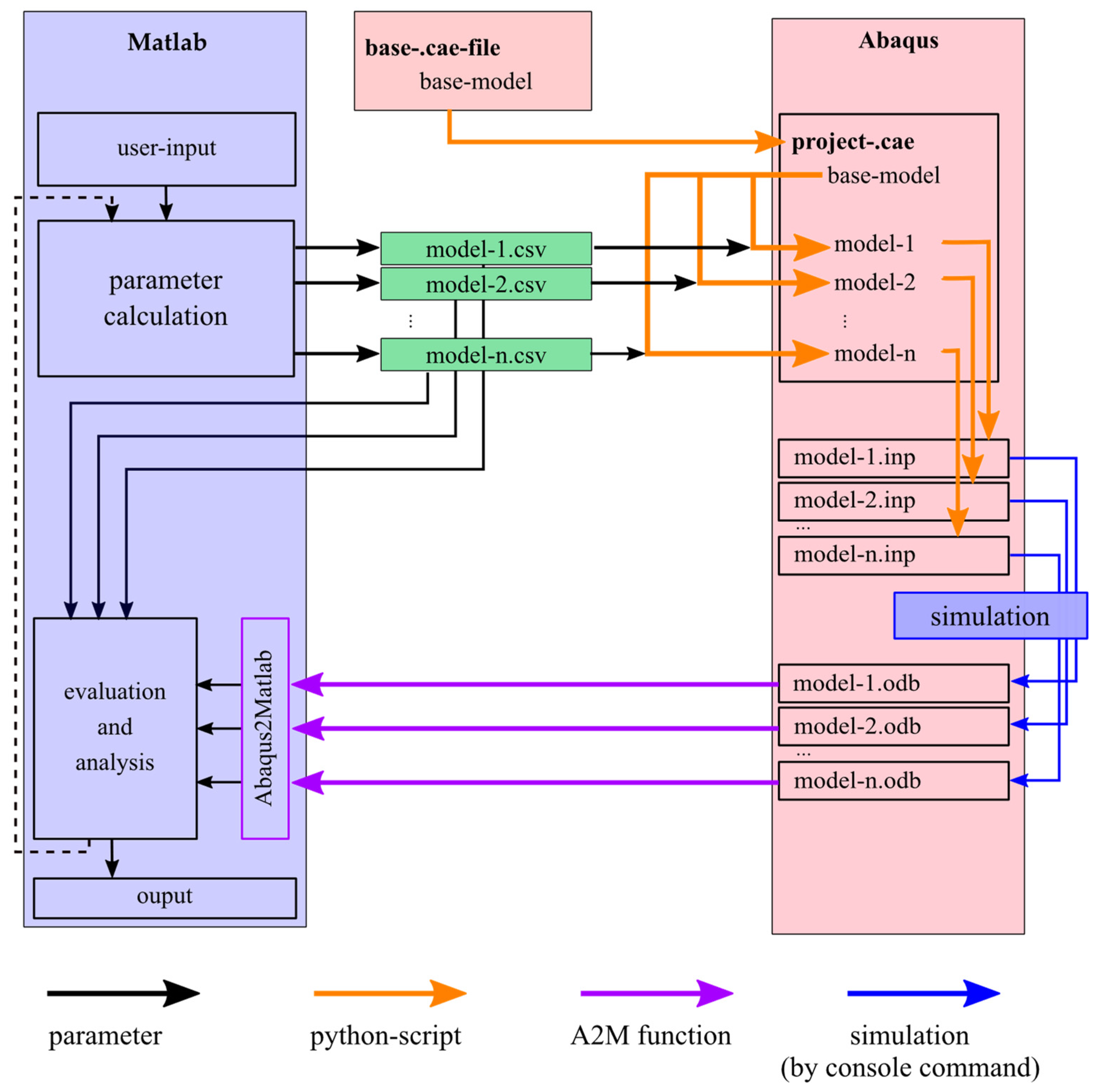
2.2.2. Structure of the Development Environment

In the following section, the structure of a development environment is presented with which automated parameter studies for coupled forming and flow simulation can be carried out and evaluated. The software components Abaqus and Matlab are used for this purpose. The height, number and outlet angle of the lubrication channels (see Figure 3) and the lubricant are defined and simulated as relevant influencing parameters for the design of the lubrication channels.
For the implementation of the flow simulation, the SPH simulation was selected as described in Section 2.2.1. Due to the high calculation times, only a section α of the forming tool could be simulated (see Figure 4a,b). The angle α represents the number n of lubrication channels (see Equation (1)).
n = 360°/α
It is assumed that the width of the groove should be as small as possible to avoid leaving marks or wrinkles on the cup. For this reason, a groove with a width of 0.3 mm is chosen as the outlet geometry, which is at the limit of what can be produced. Manufacturing restrictions indicate that it is advisable to taper the groove so that the powder can be removed more easily after the additive manufacturing process. The groove is fed with lubricant via supply channels with a diameter of d = 1 mm.
Figure 4c–i show information about the mesh in terms of element type and element size of the individual components. The lubricant is meshed as a hexahedron, which is converted into SPH particles at the start of the simulation. To ensure that the lubricant is also forced through the outlet openings, pressure must be applied to the supply channels. This is done by a displacement-controlled piston. Since no symmetry condition can be set in an SPH simulation, boundary surfaces (Figure 4i) must be provided to the left and right of the 1/n model to prevent the particles from flowing away in the circumferential direction. Due to the oil outlet groove and the lubrication channels, it is not possible to completely mesh the die as a hexahedron. For this reason, the area around the lubrication channels is meshed as a tetrahedron.
In total, the components of the model consist of three different materials, which will be discussed in the following. For the die as well as for the other tool components in Figure 4, the material 1.2709 (MS1) is assigned. Aluminum (EN AW-1080) is used for the sheet. The density and elasticity properties for tool and sheet material are shown in Table 1 below.
Furthermore, a plastic behavior is defined for the sheet. For this purpose, points of the stress–strain curve of the material must be specified, which are interpolated by Abaqus. Assuming the simplification that the yield strength marks the beginning of the plastic deformation and the maximum tensile strength is at half of the elongation at break, the following two points can be specified according to Table 2.
For the correct mapping of the lubricant, the density and viscosity properties as well as the sound velocity are required, which are shown in Table 3 for different lubricants. One of the most important equations in the field of hydrodynamics is the equation of state. The linear Us–Up Hugoniot form of the equation of state was used to represent the fluid properties.
The contact settings determine the friction behavior of the bodies among each other. For this purpose, different properties are specified for different areas and contact pairings. In Abaqus, the methods “general contact” and “surface-to-surface-contact” are used for this purpose. “General contact” describes the hydrodynamic friction of the fluid with the die and sheet with a friction coefficient of μfluid = 0.01. Since no effective surfaces can be defined for the fluid, this friction property applies globally.
The friction properties of the “surface-to-surface-contact” method locally overwrite the “general contact” definition. All frictions are created with “penalty friction” in the category “tangential behavior”. The control of time-dependent processes, which also include the stamp speed, is based on the total simulated time span tStep = 0.25 s. Thus, the stamp speed vStamp does not exceed the guideline values for the drawing speed of aluminum, which is vDrawing speed = 500 mm/s [33]. In addition, mass scaling is activated for the simulation to further reduce the time required. In doing so, the mass of all elements is scaled in such a way that a time increment of not less than 10−6 s is achieved.
The development environment for the parameter study is shown in Figure 5. The user inputs (parameter variation) and the automated evaluation are carried out in Matlab. A parameterized basic model was created in Abaqus, which can be adapted via the parameters in Matlab. For reasons of research data management, a .csv file was created for each parameter study, in which all parameter settings are noted, so that there is a clear and traceable assignment between the models, the simulation data and the evaluation. The subsequent simulation of the full-factorial parameter study as a function of α, β and h is carried out in Abaqus. For the angle, α = [10°; 15°; 20°] are simulated. For even smaller angles, the tool section is so small that it is assumed that the deep-drawing process and the lubricant distribution can no longer be mapped qualitatively. For larger angles, it is assumed that sufficient lubricant distribution is no longer given. Since self-supporting structures must be manufactured to prevent support structures in the channels, the outlet angle β must be > 90°. Assuming that the lubrication pad builds up optimally when the lubrication channel opens orthogonally into the drawing edge, β = [100°; 110°; 120°; 135°] are simulated for the outlet angle. The height h is to be determined so that the outlet groove is located in the range of the maximum contact normal stresses. Thus, the height h can only be determined on the basis of the purely mechanical forming simulation. The subsequent automated evaluation is carried out in Matlab and outputs the total work, friction work and a specially calculated wrinkle value (which describes the wrinkle formation on the sheet metal due to the forming).
For the evaluation of the simulation results, various aspects are considered in relation to the target in order to be able to quantify the effects of the process-integrated lubrication on the forming process. In addition to considering the process forces, the quality of the forming can be assessed on the basis of the formed sheet metal. For this purpose, the coordinates of the nodal points of the sheet metal are read out and processed. One challenge here is the structuring of the data points, as they are available in unsorted form. By converting them into cylindrical coordinates and including the geometry and mesh parameters from the .csv file, the coordinates of the wall area of the sheet can be filtered out and sorted into a grid structure similar to the mesh. The result of this process is a three-dimensional matrix, where the individual dimensions represent the number nz, nΘ and nr of nodes in the z, Θ and r directions, respectively. The entries of the matrix contain a reference to the indices of the unsorted coordinate matrix.
On this basis, data can now be collected that are of interest for assessing the process. These include the wall thickness and the radius as a function of the node position. Based on the outer radius, deformations of the sheet, such as wrinkles, can be detected. To examine the wrinkling more closely, the shape of the sheet metal can be viewed as a deviation from the average radius of a z-plane averaged in the Θ-direction. For this purpose, the coordinates of the outer nodes are considered, where i and j indicate the position of a node in the z- and Θ-direction, respectively, normalized to integer values. The average radius of a z-plane r ˜ i is calculated, as shown in Figure 6a, from the radii ri,j of the outer nodes of a plane, cf. Equation (2):
r ˜ i = 1 n Θ j = 0 n Θ r i , j
Starting from this, the difference Δri,j to r ˜ i is calculated for each point (cf. Figure 6c, Equation (3)) and then averaged over all i (cf. Figure 6b, Equation (4)):
Δ r ˜ i , j = r i , j r ˜ i
Δ r ( j ) = 1 n z i = 0 n z Δ r ˜ i , j
Δr(j) describes the folding of the three-dimensional outer wall of the sheet metal using a two-dimensional function.
To develop an evaluation factor with which the wrinkle formation can be described and compared on the basis of a value, the sum of the amount of the gradient of the values for Δr(j) of the last time increment is formed. Compared to the integral, the gradient takes short and strongly pronounced wrinkles more into account, as Figure 7 shows for possible courses of a short and a long wrinkle, Δrshort(j) and Δrlong(j), respectively. While the integral over the entire length is identical for both courses, the sum of the magnitude of the gradient differs by a factor of three and thus better represents the actual damage pattern. For this reason, the assessment of the wrinkling is made on the basis of the gradient. If the angle α of the simulation model is also taken into account, the quantity for assessing the wrinkling, for which the name wrinkle value is introduced, results according to Equation (5):
wrinkle   value = 360 ° α   ×   j = 0 n Θ | grad ( Δ r ( j ) ) |
At this point it should be noted that the wrinkle value does not allow any statements about the real size of the wrinkles. However, it does allow a comparison between different parameter combinations in terms of wrinkle formation.

2.3. Experimental Investigation

In the following, the experimental setup is described. Therefore, a hydraulic metering device is used to realize process-integrated lubricated strip drawing tests. These are necessary to validate the forming performance of the designed lubrication channel functionality.

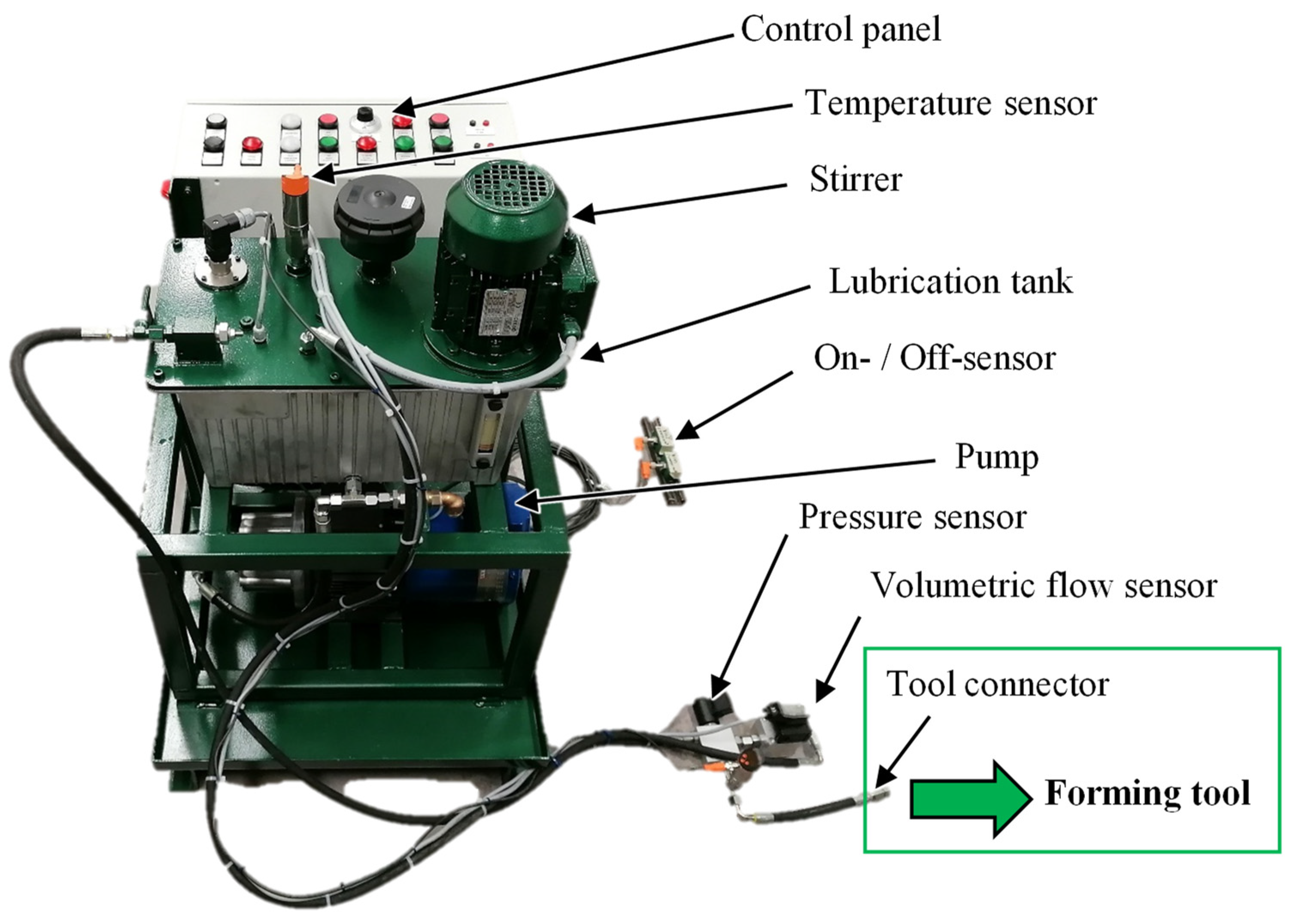
2.3.1. Hydraulic Metering Device

For the experimental tests, a hydraulic metering device is used (Figure 8). This device is manufactured by HSG-Hydraulik-Service GmbH, Wunstorf, and consists of a control cabinet, a temperature control unit, a stirrer to circulate the lubricant in a tank, a pump to convey the lubricant, a connection device to the forming tool and a magnetic on-off sensor system. A flow rate and pressure sensor are provided to detect the flow parameters. During the experiments, the lubricant is circulated by the pump upstream of the tool connection to ensure a uniform temperature progression in the system. The volume flow is adjusted step wise by setting the rotational speed of the pump. This is regulated by the signal of the volume flow sensor at the tool connection. A valve is located at the tool connection, which is controlled by the magnetic on- and off-sensors. When the system is switched by the on-sensor, the valve at the tool connection opens and the lubricant is conveyed into the test specimen. The pressure is recorded at the tool connection with a frequency of f = 1200 Hz and digitalized. The pressure sensor is a PN-400-SER14-MFRKG/US//V from IFM electronics. The volume flow sensor is a VM01 gearwheel flow meter from Profimes Gmbh.

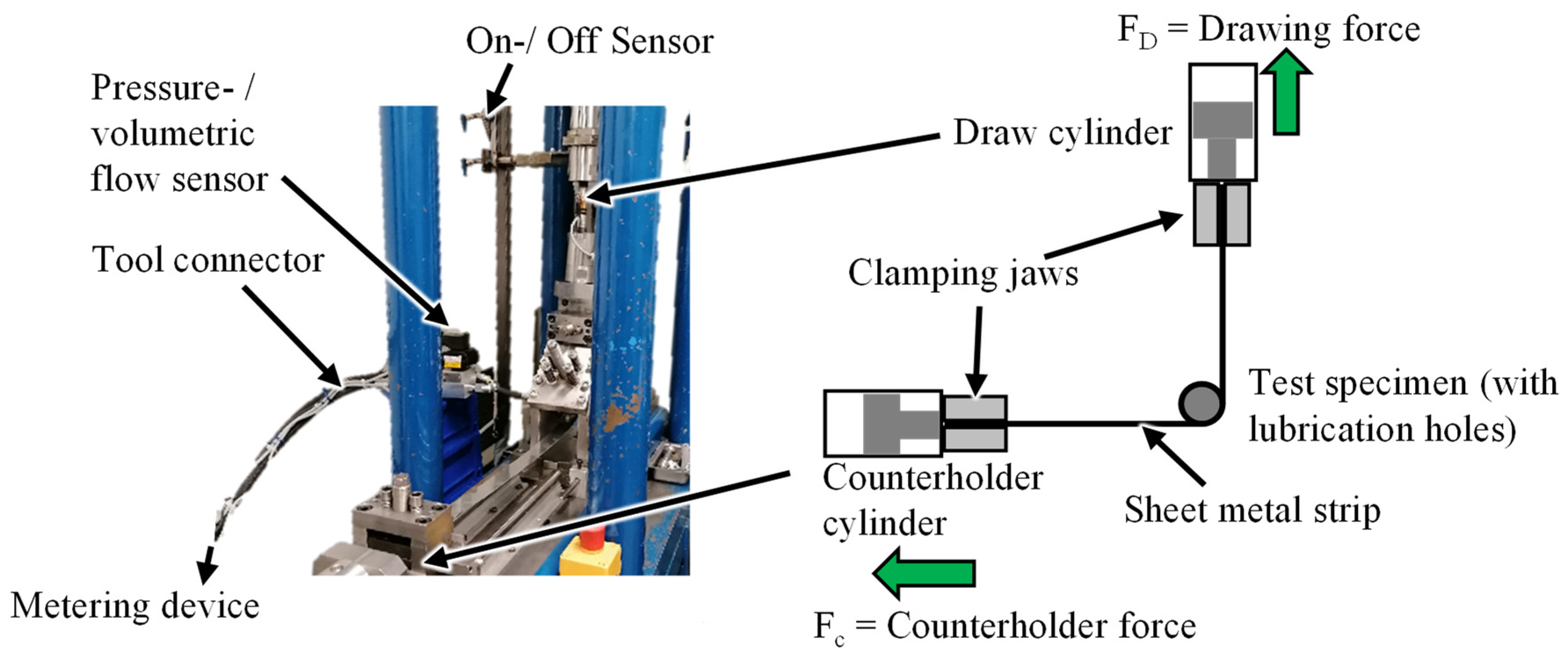
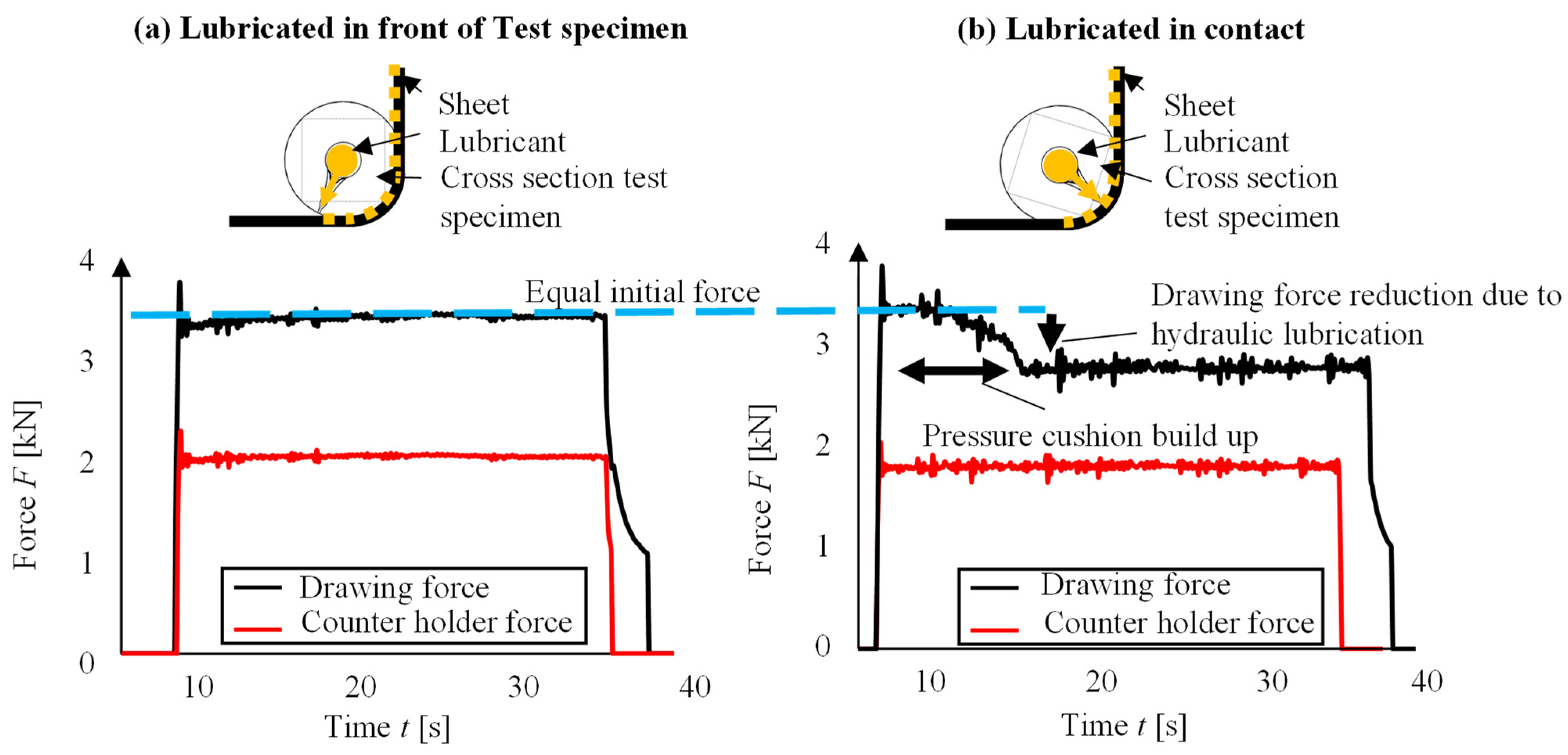
2.3.2. Strip Drawing Tests

The experiments are carried out at a strip drawing test stand at the Institute of Forming Technology and Machines (IFUM). The strip drawing test simulates the load situation occurring on a drawing edge of a forming tool. For this purpose, a sheet metal strip is drawn around a cylindrical test specimen. The counterholder force FC is set to a constant value and the tensile force FD varies depending on the sheet material and the friction conditions between the test specimen and the sheet strip (see Figure 9). Both force progression curves are recorded during the experiments. A constant drawing speed of vDraw = 10 mm/s and a constant counterholder force of FC = 2 kN are set as test parameters.
The forming speed was selected here in order to make the build up-phase of the pressure pad visible. This simplification was chosen for the experimental scale since the handling of the volume flow is more controllable for longer lubrication phases.
The sheet metal strips are made of EN AW-1080 material with a width of wsheet = 30 mm and a thickness of tsheet = 0.8 mm. The cylindrical test specimens have a diameter of dspecimen = 16 mm. During the test, the tensile cylinder pulls the sheet metal strip over the forming head at an angle of 90°. After a test time of t = 1 s, lubricant is pumped to the forming zone by the hydraulic metering device. The overall test time is t = 37 s. At the end of the test, the metering device switches off and no lubricant is pumped. In order to provide lubrication at the start of the test, the first 20 mm of the sheet metal strip are manually lubricated with the lubricant beforehand. The lubricant is tempered to a constant temperature of T = 40 ± 3 °C.

3. Results

In the following, the results of the simulation and forming tests are presented and analyzed. First the mechanical simulation to identify the areas of maximum tool loads of the demonstrator process is presented. Afterwards the results of the coupled forming and flow simulation are presented. For this purpose, a full factorial parameter study is carried out. In the following, the parameter field α = [10°; 15°; 20°], β = [100°; 110°; 120°; 135°] and h = [2 mm; 2.5 mm; 5 mm; 5.5 mm] is analyzed for the five different lubricants from Table 3. It has been shown that the influence of the lubricant has approximately no influence on the forming result. With 8 CPUs, the simulation time of the reduced 1/n model was between 8 h to 12 h. At the beginning, the results on the build-up and propagation of the fluid pad are presented. Then, the evaluation of the friction work and finally that of the wrinkling are discussed.
The focus of the experimental investigations is set on evaluating the influence of the injection position, the lubricant and the outlet geometry of the test specimen grooves on the reduction in the drawing force. In addition, the fluid mechanical formation of the pressure cushion is analyzed. For this purpose, both the volume flow and the pressure are measured and recorded.

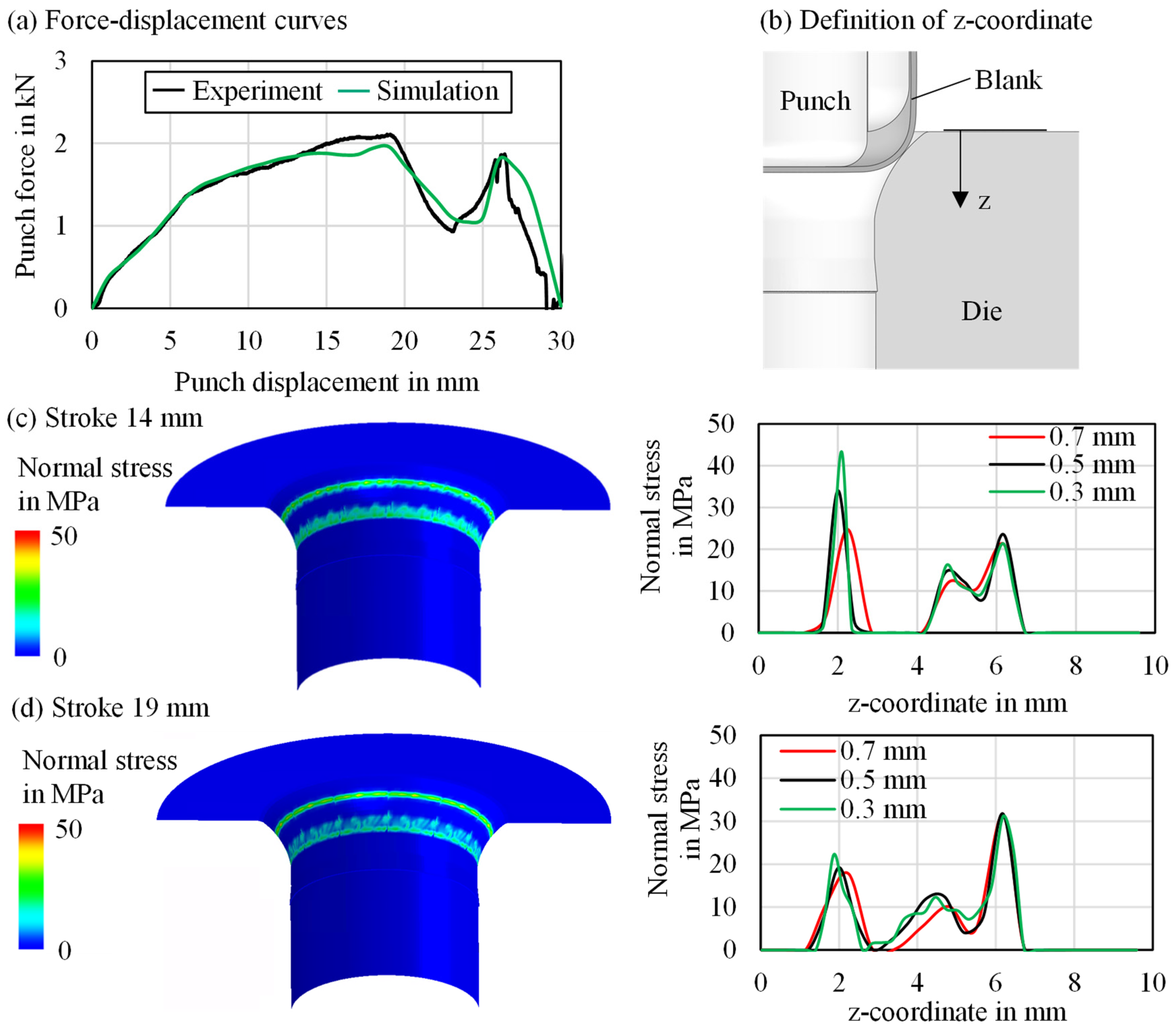
3.1. Mechanical Simulation

For a validation of the mechanical simulation model, the numerically calculated force-displacement curve is compared to the experimental, which was measured in exemplary deep-drawing test. In Figure 10a, it can be seen that a high agreement is achieved by the numerical model. Apart from the maximum forming force, which is slightly underestimated in the simulation, the curves show a high agreement at the beginning and the end of the forming process. Therefore, the material model and the friction conditions are evaluated as applicable for the further investigation. In the next step, the contact normal stresses on the die are evaluated in the second forming step. In Figure 10c,d, the maximum contact stresses are shown at different punch strokes as a function of the coordinate z, which is defined as the height from the top edge of the die, shown in Figure 10b. Two linear contact areas develop on the drawing edge during forming. At the beginning of the process, the cup comes into contact with the upper area of the drawing edge, creating the first linear contact area. Subsequently, the bottom of the cup is bent over by the punch and drawn further into the die until it gets in contact with the lower area of the drawing edge, where the second contact area is formed. Between these areas, a minimal gap between the surface of the cup and the die is present, thus no contact stresses occur. The maximum normal stresses in the upper contact area are present at a stroke of 14 mm, which can be seen in Figure 10c. In the lower contact area, the maximum contact stresses occur at a stroke of 19 mm, when the maximum punch force is reached, which is shown in Figure 10d. Since the contact stresses are dependent on the applied mesh size, the resulting stresses are plotted for different element edge lengths.
Figure 10c,d show that different mesh sizes have a significant effect on the resulting contact normal stresses. A finer mesh results in higher contact stresses. Therefore, it is difficult to determine specific values. However, it can be seen that the maximum loads on the drawing edge are in the range of z = 2 mm as well as between z = 5 and 6 mm. Thus, the oil outlets are positioned in this range to reduce the frictional load on the surface of the die as well as the workpiece.

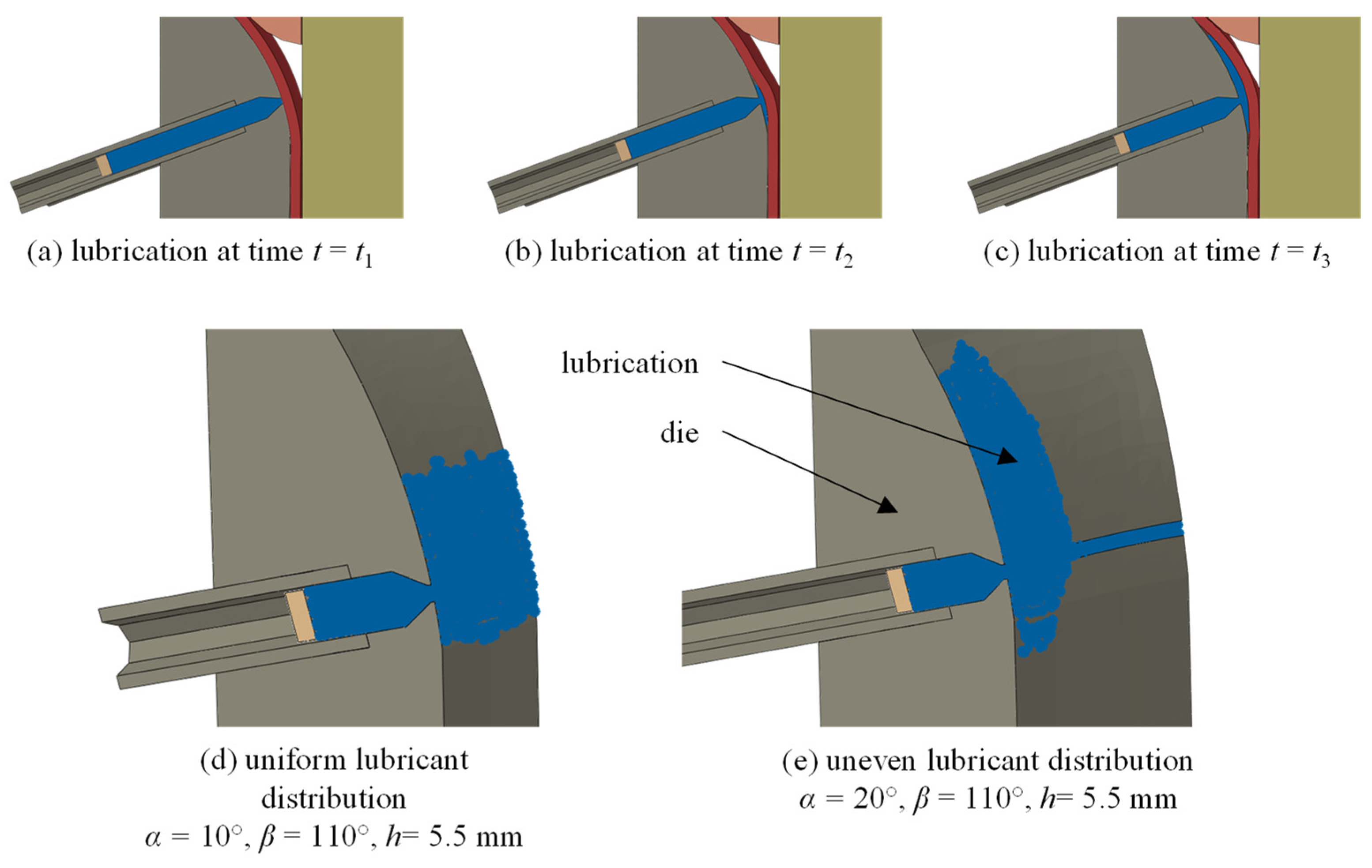
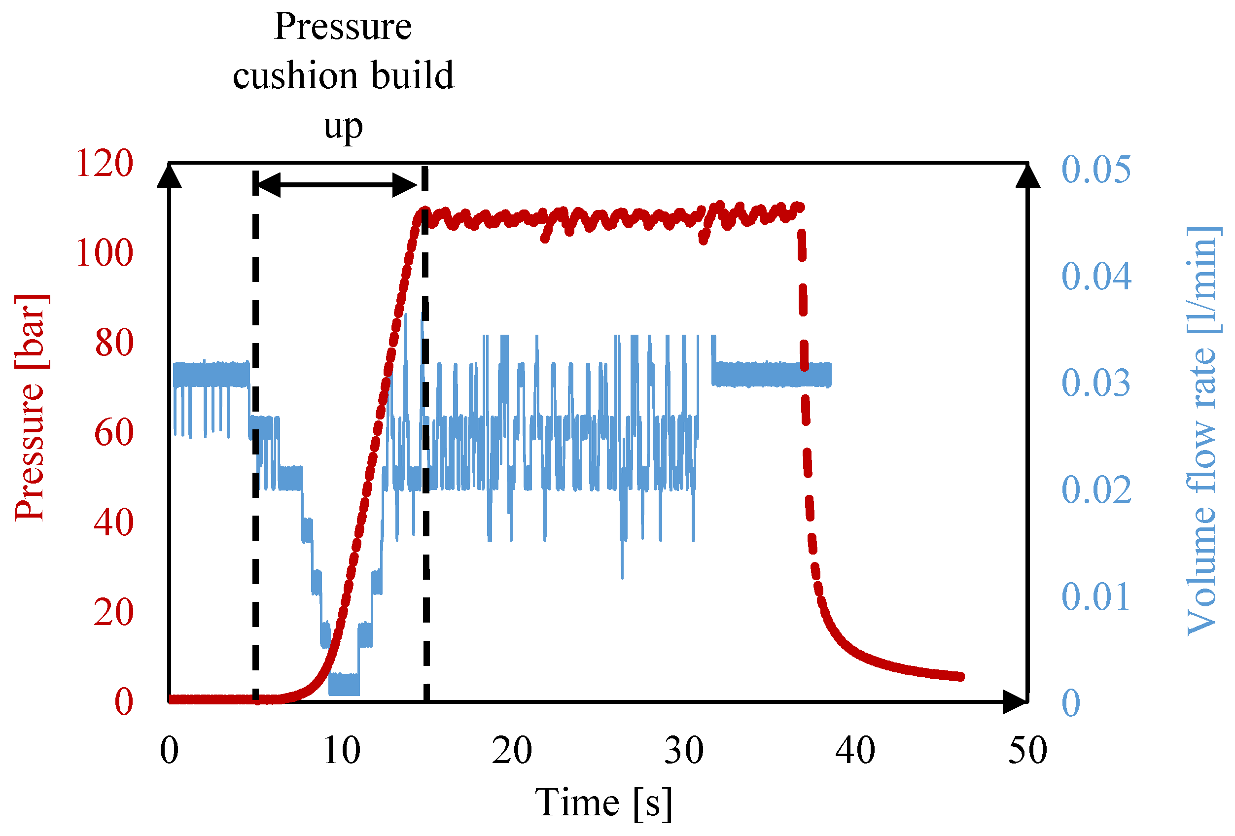
3.2. Build-Up and Propagation of the Fluid Pad

The simulation results show that the pressure between fluid and sheet successfully builds up and a fluid pad spreads (Figure 11a–c). However, depending on the selected parameters, the fluid cushion sometimes only spreads on one side (Figure 11e), which leads to increased wrinkle formation. On the other hand, a homogeneous lubricant distribution (Figure 11d) allows for less wrinkling. In order to be able to make detailed statements about the quality of the forming result, the results of the friction work are presented in Section 3.3 and the results of the wrinkle value in Section 3.4.

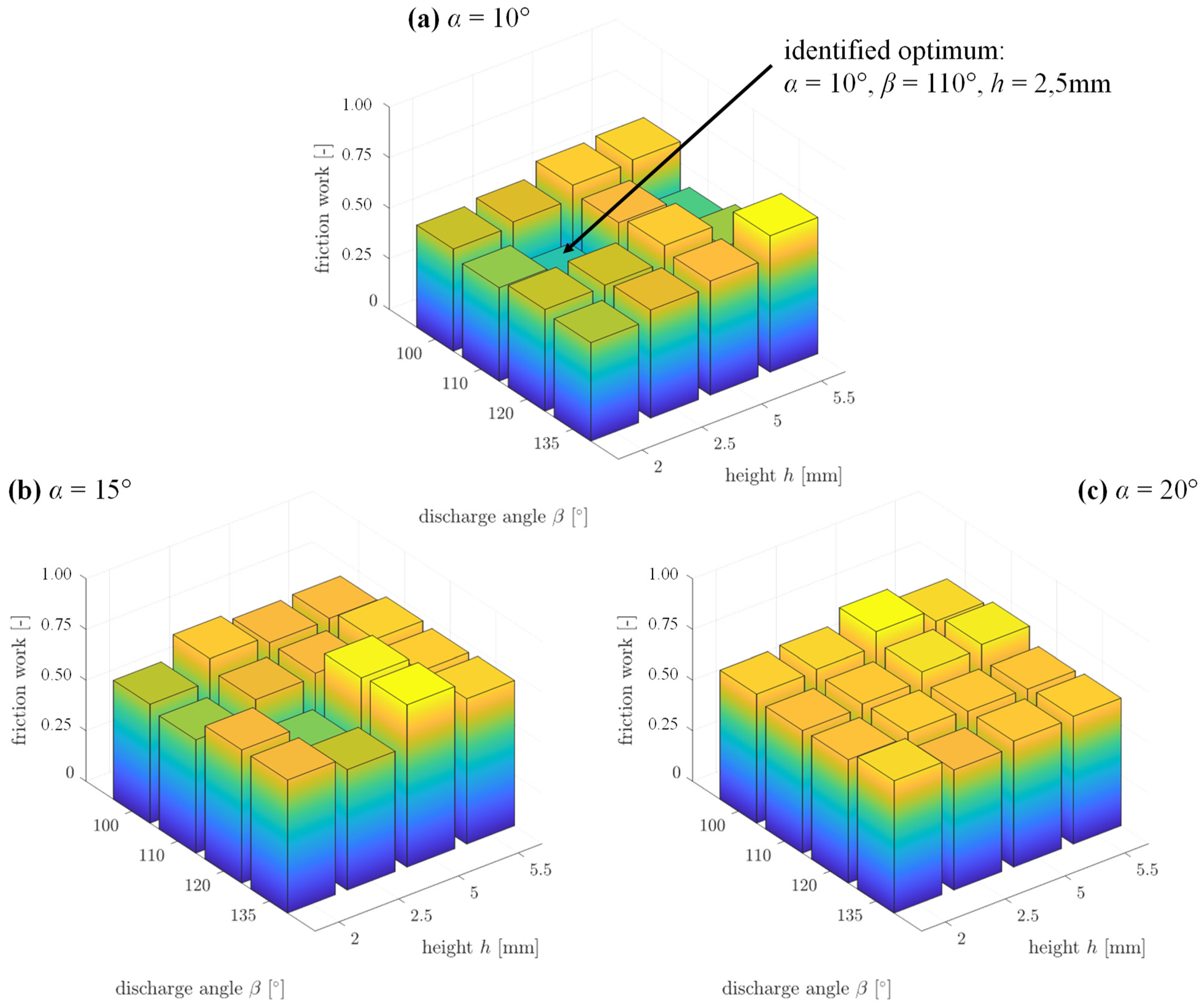
3.3. Evaluation of the Friction Work

Figure 12 shows the results of the friction work of the full factorial parameter study. It should be noted that the values were normalized to 1 for a qualitative comparison. The greatest influence on the friction work is the number of lubrication channels, which is expressed by the angle α. The smaller the angle α or the more lubrication channels are used, the smaller the friction work. For the parameters β and h, no generally valid correlations can be identified for the parameter combinations investigated. For α = 10°, however, it is evident that a low friction work can be realized for β = 110°. From preliminary studies it could already be determined that a low friction work can be realized if the height h lies in the upper contact area h = [2 mm; 2.5 mm] or the lower contact area h = [5 mm; 5.5 mm]. The global optimum of the friction work is identified for α = 10°, β = 110° and h = 2.5 mm. This is followed insignificantly worse by the parameter combination α = 10°, β = 110° and h = 5.5 mm.

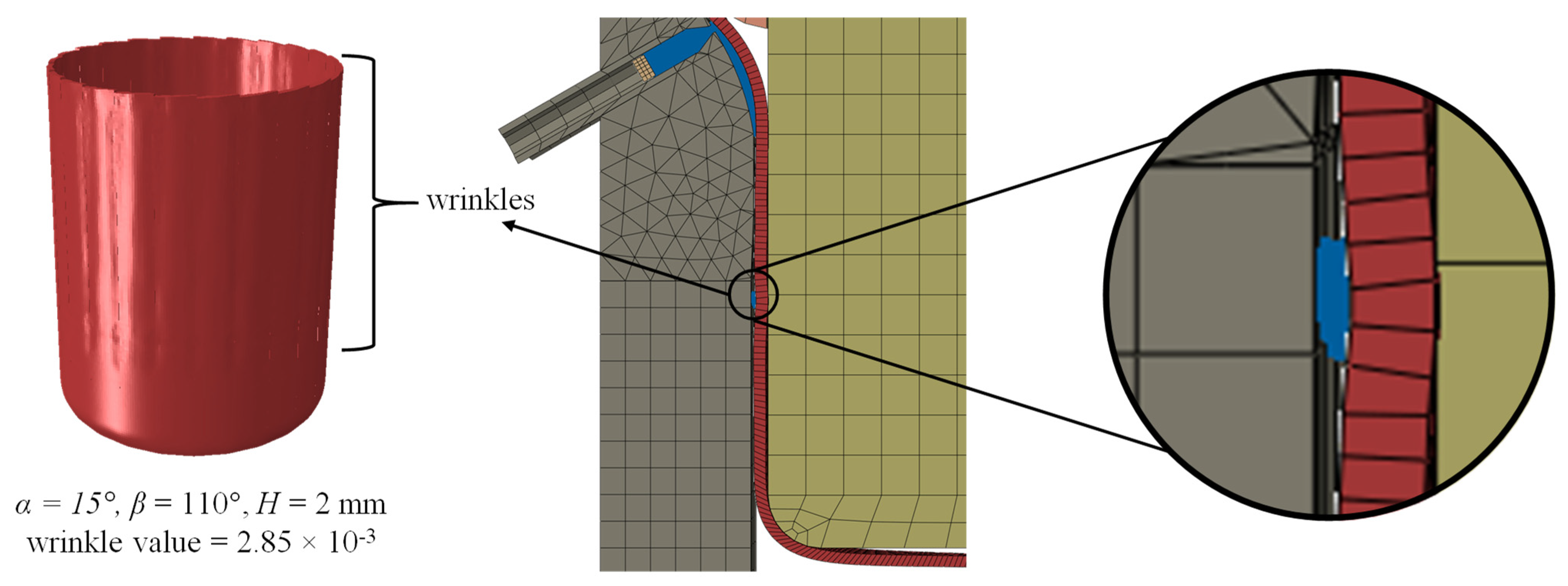
3.4. Evaluation of the Wrinkling

Figure 13 shows the results of the wrinkle value as a function of the parameters α, β and h. It should be noted that the values were normalized to 1 for a qualitative comparison. The lowest values of the wrinkle value can be realized for α = 10°. These are consistently lower than for α = 15°. It is noticeable that the wrinkle values for α = 20° are lower than for α = 15°. For the parameters β and h, no characteristic correlations can be identified for the parameter combinations investigated. The global optimum of the wrinkle value is identified for α = 10°, β = 110° and h = 5.5 mm. The parameter combination α = 10°, β = 110° and h = 2 mm follows insignificantly worse. Considering the friction work and the wrinkle value, the parameter combinations α = 10°, β = 110° for different heights h = [2 mm, 2.5 mm, 5.5 mm] are the most suitable.
In order to assess the wrinkle value, the next step is to present the results of the coupled SPH and forming simulations for the most promising parameters (see Figure 14). By extending the 1/n model rotationally to a complete body, the wrinkles of the sheet metal component become visible. It can be seen that a high wrinkle value (α = 15°, β = 110° and h = 2 mm) is accompanied by an optically poor forming result. The optically lowest wrinkling coincides with the lowest calculated wrinkle value (α = 10°, β = 110° and h = 5.5 mm). Thus, for the assessment of the deep-drawing result, the formula relationship of the wrinkle value is suitable.
It is noticeable that all cups have visually visible wrinkles. This can be explained by an analysis of the lubricant film (see Figure 15). Small SPH particles are moved downwards with the sheet metal. The gap between stamp and die is 0.65 mm and the sheet metal before forming is 0.42 mm. Since the SPH particles have an element size of 0.15 mm and cannot be deformed, the sheet metal is inevitably deformed, which leads to increased wrinkling.

3.5. Validation of the Lubrication Concept

Based on the friction work and wrinkle value, the next step is to derive the most promising channel design for validation on a forming head with integrated lubrication channels. It has been shown that with a high number of lubrication channels, both the friction work and the wrinkle value are low (α = 10°, β = 110° for different heights h = [2 mm, 2.5 mm, 5.5 mm]). The feed ducts should be conical and have a minimum cross-section of d = 1 mm so that the powder can be removed after the additive manufacturing process. Otherwise, there is a risk that the channels will clog and an uneven pressure distribution will result. The main feed channel of the mold head branches into 13 feed channels, which lead into a tapering groove with an outlet gap of 0.3 mm width. The minimum outlet gap width was determined by an experimental parameter study in which different outlet gap widths were manufactured and analyzed for dimensional accuracy and openness using computer tomography. On the one hand, the expansion of the groove into the interior of the component should help to ensure that the powder can be easily removed from the additive manufacturing process. On the other hand, the expansion of the groove should prevent clogging of the groove due to possible particle abrasion between the sheet metal and the die, or at least ensure that the groove can be cleaned. The spacing of the individual supply channels is 1 mm. This realizes a similar behavior as in the SPH forming simulation of the deep-drawn cup. However, the height h of the lubrication channels cannot be investigated in the case of the forming head, as there is only one and not two areas of maximum contact normal stress. No pressure pad would build up above or below the range of maximum contact normal stress. For the same reason, the outlet angle β = 135° is chosen so that the outlet groove is orthogonal to the drawing edge and the lubricant does not flow off laterally. The test specimen is shown in Figure 16. Alternatively, a second test specimen is investigated, with multiple single channel slots which are each fed by inlet channels. The volume flow of the lubricant is set constant to V = 35 mL/min. Experiments are carried out in which the lubricant is injected both upstream the forming zone and directly in the forming zone (see Figure 17). The metering device is set to a maximum feed pressure of p = 110 bar.

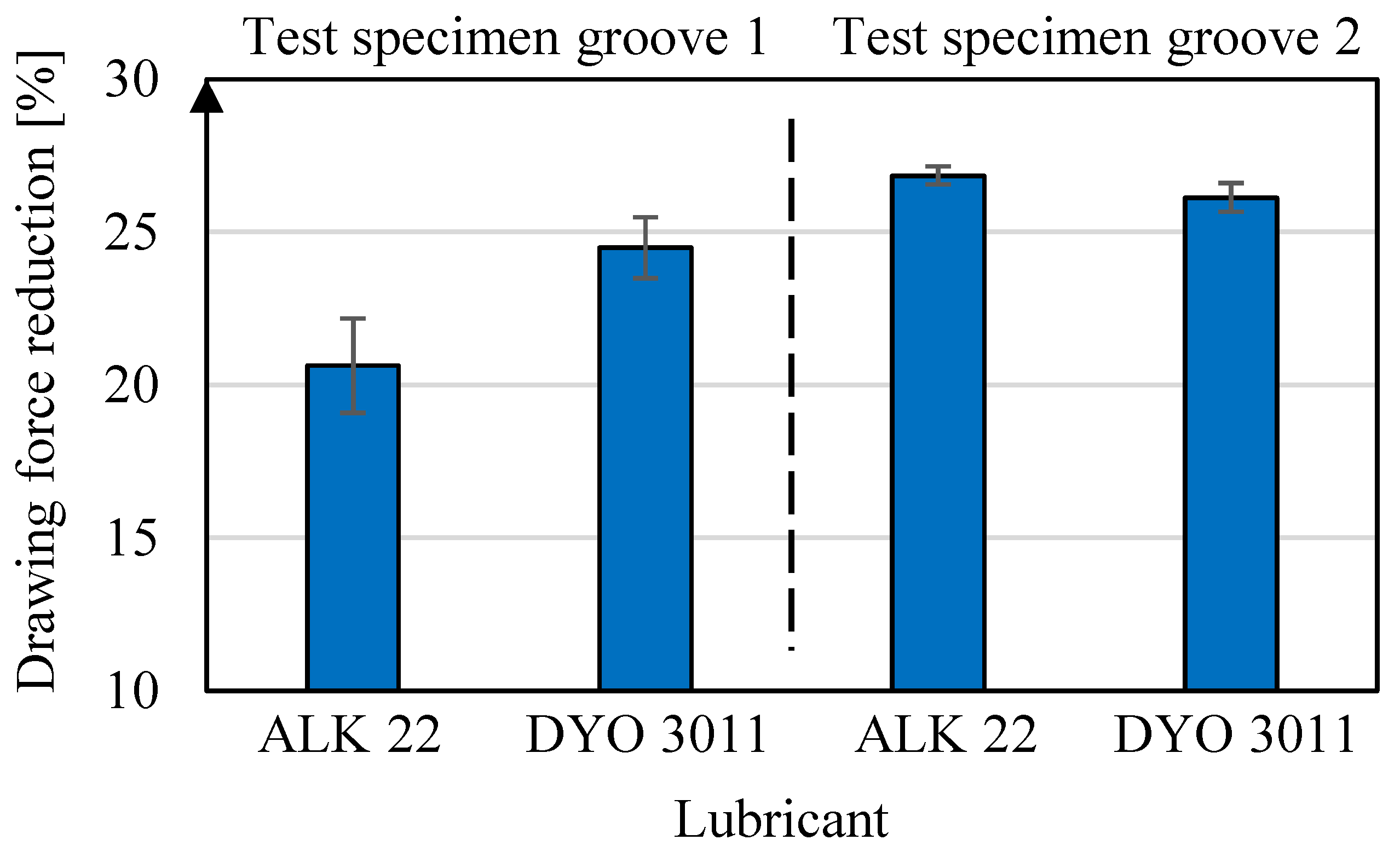
3.6. Forming Experiments

By applying the lubricants Multicut ALK 22 and Renoform DYO 3011 upstream of the forming zone, it is stated that the drawing force progresses constantly along a constant value (see Figure 17a). No pressure cushion is formed and the lubrication conditions are comparable to manual lubricated sheet metal strips. By injecting the lubricants directly into the forming zone in the sheet contact, it can be seen that the drawing force decreases significantly as a pressure cushion builds up between the test specimen and the sheet strip (see Figure 17b). The initial drawing force at the beginning of the tests is the same for both contact situations. After the pressure cushion built up, the drawing force FD runs horizontally again, but is significantly reduced. Therefore, it can be assumed that a mixed friction condition occurs for a lubrication situation before the forming zone and a hydrodynamic friction condition occurs for a lubrication in the forming zone.
Figure 18 shows the course of the pressure and the volume flow at the tool connection during a test for a hydraulic lubrication in the tool contact of the forming zone. Analogous to the course of the drawing force in Figure 17b, it can be seen that the build-up of the pressure cushion takes between t = 7 s and 8 s. In this phase, the flow rate drops to approx. V = 5 mL/min as the outlet openings of the lubrication channels are closed by the sheet metal strip. As soon as the pressure is regulated to a constant value of p = 110 bar, the volume flow shows a horizontal progression of V = 23 ± 10 mL/min. This can be explained by the fact that the pressure cushion is not perfectly closed and lubricant is constantly transported out of the forming zone with the relative movement between test specimen and sheet metal strip. At the end of the test, the lubrication feed into the test specimen is closed and the pressure in the feed line drops back to the initial value.
Figure 19 shows the percentage reduction in drawing force for tests hydraulically lubricated in the forming zone after pressure cushion built up compared to the tests before the pressure cushion was built up. It can be seen that due to the hydrodynamic pressure cushion, a force reduction of between 21% and 27% is achieved for both lubricants and test specimens (see Figure 19). For experiments with test specimen 2 (single channel slots), a slightly higher force reduction tends to be observed (approx. 6% for Multicut ALK 22 and approx. 3% for Renoform DYO 3011). This suggests that locally stronger pressure cushions are formed by the individual outlet slots of test specimen 2, which improve the friction conditions between sheet metal strip and test specimen. For a continuous slot in test specimen 1, it appears that pressure peaks cannot build up locally as for test specimen 2 because the lubricant is distributed constantly across the width of the contact area. However, since the values for both outlet geometries do not differ significantly, no definite statement can be given here. Nevertheless, it can be stated that an active hydraulic lubrication at the point of highest contact normal stresses significantly improves friction conditions.
The filigree deterministic variation of the channel geometry realized with the technology of additive manufacturing made it possible, that process-integrated lubrication can be used and optimized for small component geometries in multi-stage tools. According to the current state of the art, process-integrated lubrication is only used for larger components (>100 mm). In addition, the tools had to be assembled segment by segment and sealed with sealing rings, which means a more complex and maintenance-intensive tool design [11,34,35]. A geometrical variation of the outlets in order to achieve a more optimal lubrication pad distribution or to avoid indentations on the semi-finished products, for example by groove or slot geometries, could therefore not be carried out or only insufficiently. Especially for small drawing parts, for example for the cosmetics industry, the narrowest possible optimally designed channel openings, which do not leave any indentations, are essential to make process-integrated lubrication applicable for this industry. The results show that it is also possible to use the advantages of process-integrated lubrication (reduction in friction, saving of intermediate lubrication steps, saving of lubricants, etc.) in this industrial sector. In addition, it was proven that the lubrication performance can be individually adapted and improved by geometric variation of the channels.

4. Discussion

It was found that as the number of lubrication channels increases, the friction work and the wrinkle value decrease. It must be taken into account that the number of supply channels is not the only factor that can be inferred by a small α. By having a high number of supply ducts running into the outlet groove, a high outlet cross-section of the supply ducts is realized. In order to maximize this, which expresses a small α, fewer lubrication channels with larger diameters can be realized. This would be particularly advantageous with regard to powder removal after the additive manufacturing process.
It has been shown that the specially derived wrinkle value represents well the forming result with regard to wrinkles. It is noticeable that all cups have visible wrinkles. The high wrinkle value can be attributed, among other things, to particles pulled down with the sheet metal. These leave marks on the cup. In further parameter studies, the gap below the drawing edge should be enlarged. Since a bouncing of the sheet could not be observed, the gap width has no further influence on the forming result. Another alternative would be to reduce the element size of the SPH particles. However, this would involve an increased computational effort. With these two measures, a better forming result can be expected in the simulation. Subsequently, a detailed material model for the sheet metal should be used in further work, which, for example, represents the anisotropic material properties.
The forming experiments show that a hydraulic lubrication in the contact zone has the highest effect in terms of reducing drawing force. This can be explained by pressure cushion build-up between sheet and test sample. The pressure cushion creates a hydrodynamic contact situation. A force reduction of between 21% and 27% is achieved this way. Compared to a continuous outlet groove, multiple channel slots seem to cause a greater reduction in drawing force. This can be declared by the assumption that locally larger pressure peaks are formed due to the isolated outlet openings.
Furthermore, based on the numerical results, a quarter model of the coupled SPH and forming simulation should be built for the most promising parameter combinations. In this way, the boundary effects in the formation of the lubrication pad by the bounding walls can be minimized. Another limitation of this approach is that only rotationally symmetrical deep-drawn parts can be simulated.
With the simulation model presented here, it should be noted that the model is simplified with regard to the feed channels and the design of the groove. For example, the path of the feed channels must change in order to realize the pressure build-up via a feed channel. However, this pressure build-up cannot be simulated because the number of SPH particles would increase exorbitantly.
Based on the results and findings presented here, Figure 20 shows a design of the forming tool for lipstick tubes with process-integrated lubrication. For a homogeneous lubricant distribution, the supply channel runs in two tori, which are connected to each other via supply channels. Subsequently, the upper torus runs into an outlet groove with an outlet diameter of 0.3 mm. Furthermore, slots are provided for a thermocouple and a heating cartridge to temper the oil. The production and experimental validation of the forming tool will be considered in further work. The validation of the simulation model presented here on the basis of experimental results is also to be carried out in further work. In addition, the influence of the forming speed in the tool system is to be investigated for higher speeds in further work.

5. Conclusions

The coupled SPH and forming simulation showed that the lubrication channels should be located in the area of the upper or lower maximum contact normal stresses. Furthermore, the feed cross-section to the outlet groove should be as large as possible. The self-derived wrinkle value is suitable for describing wrinkles on the sheet metal well. The outlet angle of the lubrication channels should be β = 110°. The experiments showed that single channel openings should be investigated in more detail as lubrication channel outlet slots for forming tools. In addition, the formation of pressure cushions between tool and component should be aimed for, as these cause hydrodynamic contact conditions, which improve the friction situation. From the practical tests, it could be concluded that the drawing force decreases by 21% and 27% with pressure cushion build up.

Author Contributions

Conceptualization, T.E., P.A. and P.M.; methodology, T.E., P.A. and P.M.; software, T.E., M.O. and P.A.; validation, T.E., P.A., P.M., B.-A.B., R.L., S.H., H.W., P.C.G., M.O. and E.F.; formal analysis, T.E., P.A. and P.M.; investigation, T.E., P.A., M.O. and P.M.; resources, B.-A.B., R.L., S.H., H.W. and P.C.G.; data curation, T.E., P.A. and P.M.; writing—original draft preparation, T.E., P.A. and P.M.; writing—review and editing, T.E., P.A., P.M., B.-A.B., R.L., S.H., H.W., P.C.G., M.O. and E.F.; visualization, T.E., P.A. and P.M.; supervision, B.-A.B., R.L., S.H. and H.W.; project administration, B.-A.B., R.L., S.H. and H.W.; funding acquisition, B.-A.B., R.L., S.H., H.W., E.F. and T.E. All authors have read and agreed to the published version of the manuscript.

Funding

This research was funded by the IGF—Industrielle Gemeinschaftsforschung, grant number 21586N and “The APC was funded by the IGF—Industrielle Gemeinschaftsforschung”.

Institutional Review Board Statement

Not applicable.

Informed Consent Statement

Not applicable.

Data Availability Statement

The data presented in this study are available on request from the corresponding author.

Conflicts of Interest

The authors declare no conflict of interest.

References

  1. Birkert, A.; Haage, S.; Straub, M. Umformtechnische Herstellung Komplexer Karosserieteile; Springer: Berlin/Heidelberg, Germnay, 2013; ISBN 978-3-642-34669-9. [Google Scholar]
  2. Behrens, B.-A.; Hübner, S.; Müller, P.; Besserer, H.-B.; Gerstein, G.; Koch, S.; Rosenbusch, D. New Multistage Sheet-Bulk Metal Forming Process Using Oscillating Tools. Metals 2020, 10, 617. [Google Scholar] [CrossRef]
  3. Merklein, M.; Schmidt, M.; Tremmel, S.; Wartzack, S.; Andreas, K.; Häfner, T.; Zhao, R.; Steiner, J. Investigation of Tribological Systems for Dry Deep Drawing by Tailored Surfaces. Dry Met. Form. 2015, 1, 42–56. [Google Scholar]
  4. Behrens, B.-A.; Tillmann, W.; Biermann, D.; Hübner, S.; Stangier, D.; Freiburg, D.; Meijer, A.; Koch, S.; Rosenbusch, D.; Müller, P. Influence of Tailored Surfaces and Superimposed-Oscillation on Sheet-Bulk Metal Forming Operations. JMMP 2020, 4, 41. [Google Scholar] [CrossRef]
  5. Ravi Kumar, D.; Manohar, M. Determination of Process Parameters in Multi-Stage Hydro-Mechanical Deep Drawing by FE Simulation. J. Phys. Conf. Ser. 2017, 896, 12061. [Google Scholar] [CrossRef] [Green Version]
  6. Kunze, T.; Mousavi, A.; Stucky, T.; Böttcher, F.; Roch, T.; Brosius, A.; Lasagni, A. Tribological Optimization of Dry Forming Tools. Dry Met. Form. 2016, 2, 78–82. [Google Scholar]
  7. Üstünyagiz, E.; Altan, T. Design of Progressive Die Sequence by Considering the Effect of Friction, Temperature and Contact Pressure. KEM 2018, 767, 232–239. [Google Scholar] [CrossRef]
  8. Altan, T. (Ed.) Sheet Metal Forming; ASM International: Materials Park, OH, USA, 2012; ISBN 978-1-61503-842-8. [Google Scholar]
  9. Hoffmann, H.; Hoogen, M.; Panknin, W. Umformwerkzeug. Patent 19944722, 17 September 1999. [Google Scholar]
  10. Sekita, T.; Kaneto, S.; Hasuno, S.; Sato, A.; Ogawa, T.; Ogura, K. Materials and Technologies for Automotive Use. Jfe Tech. Rep. 2004, 2, 1–16. [Google Scholar]
  11. Klöpsch, C. Generierung Lokaler, Hydrostatischer Druckschmierungszustände beim Tiefziehen. Ph.D. Thesis, Tehnische Universität Darmstadt, Darmstadt, Germany, 2009. [Google Scholar]
  12. Ehlers, T.; Lachmayer, R.; Vajna, S.; Halle, T. Producibility. In Integrated Design Engineering; Vajna, S., Ed.; Springer International Publishing: Cham, Switzerland, 2020; pp. 287–323. ISBN 978-3-030-19356-0. [Google Scholar]
  13. Armillotta, A.; Baraggi, R.; Fasoli, S. SLM tooling for die casting with conformal cooling channels. Int. J. Adv. Manuf. Technol. 2014, 71, 573–583. [Google Scholar] [CrossRef] [Green Version]
  14. Shinde, M.S.; Ashtankar, K.M. Additive manufacturing–assisted conformal cooling channels in mold manufacturing processes. Adv. Mech. Eng. 2017, 9, 168781401769976. [Google Scholar] [CrossRef]
  15. Zhang, C.; Wang, S.; Li, J.; Zhu, Y.; Peng, T.; Yang, H. Additive manufacturing of products with functional fluid channels: A review. Addit. Manuf. 2020, 36, 101490. [Google Scholar] [CrossRef]
  16. Lachmayer, R.; Lippert, R.B. Entwicklungsmethodik für die Additive Fertigung; Springer: Berlin/Heidelberg, Germany, 2020; ISBN 978-3-662-59788-0. [Google Scholar]
  17. Kumke, M.; Watschke, H.; Vietor, T. A new methodological framework for design for additive manufacturing. Virtual Phys. Prototyp. 2016, 11, 3–19. [Google Scholar] [CrossRef]
  18. Abt, M.; Roch, A.; Qayyum, J.A.; Pestotnik, S.; Stepien, L.; Abu-Ageel, A.; Wright, B.; Ulusoy, A.C.; Albrecht, J.; Harle, L.; et al. Aerosol-Printed Highly Conductive Ag Transmission Lines for Flexible Electronic Devices. IEEE Trans. Compon. Packag. Manufact. Technol. 2018, 8, 1838–1844. [Google Scholar] [CrossRef]
  19. Urbanek, S.; Ponick, B.; Taube, A.; Hoyer, K.-P.; Schaper, M.; Lammers, S.; Lieneke, T.; Zimmer, D. Additive Manufacturing of a Soft Magnetic Rotor Active Part and Shaft for a Permanent Magnet Synchronous Machine. In Proceedings of the 2018 IEEE Transportation Electrification Conference and Expo (ITEC), Long Beach, CA, USA, 13–15 June 2018; pp. 668–674. [Google Scholar]
  20. Dennig, H.-J.; Zumofen, L.; Stierli, D.; Kirchheim, A.; Winterberg, S. Increasing the safety against scuffing of additive manufactured gear wheels by internal cooling channels. Forsch. Ingenieurwes. 2021, 86, 595–604. [Google Scholar] [CrossRef]
  21. Ehlers, T.; Tatzko, S.; Wallaschek, J.; Lachmayer, R. Design of particle dampers for additive manufacturing. Addit. Manuf. 2021, 38, 101752. [Google Scholar] [CrossRef]
  22. Ehlers, T.; Lachmayer, R. Design of Particle Dampers for Laser Powder Bed Fusion. Appl. Sci. 2022, 12, 2237. [Google Scholar] [CrossRef]
  23. Ehlers, T.; Meyer, I.; Oel, M.; Bode, B.; Gembarski, P.C.; Lachmayer, R. Effect-Engineering by Additive Manufacturing. In Innovative Product Development by Additive Manufacturing; Lachmayer, R., Bode, B., Kaierle, S., Eds.; Springer Nature Switzerland AG: Cham, Switzerland, 2022; pp. 1–19. ISBN 978-3-031-05917-9. [Google Scholar]
  24. Wurst, J.; Schneider, J.A.; Ehlers, T.; Mozgova, I.; Lachmayer, R. Corporate Strategy Based Quantitative Assessment of Sustainability Indicators at the Example of a Laser Powder Bed Fusion Process. In Sustainable Design and Manufacturing; Scholz, S.G., Howlett, R.J., Setchi, R., Eds.; Springer: Singapore, 2022; pp. 34–44. ISBN 978-981-16-6127-3. [Google Scholar]
  25. Ostermann, F. Anwendungstechnologie Aluminium; 3. Neu Bearbeitete Auflage; Springer: Berlin/Heidelberg, Germany, 2014; ISBN 978-3-662-43806-0. [Google Scholar]
  26. Keller, M.C.; Braun, S.; Wieth, L.; Chaussonnet, G.; Dauch, T.; Koch, R.; Höfler, C.; Bauer, H.-J. Numerical Modeling of Oil-Jet Lubrication for Spur Gears using Smoothed Particle Hydrodynamics. In Proceedings of the 11th International SPHERIC Workshop, Munich, Germany, 14–16 June 2016. [Google Scholar]
  27. Liu, G.R.; Liu, M.B. Smoothed Particle Hydrodynamics; World Scientific: Singapore, 2003; ISBN 978-981-238-456-0. [Google Scholar]
  28. Keller, M.C.; Braun, S.; Wieth, L.; Chaussonnet, G.; Dauch, T.F.; Koch, R.; Schwitzke, C.; Bauer, H.-J. Smoothed Particle Hydrodynamics Simulation of Oil-Jet Gear Interaction1. J. Tribol. 2019, 141, 071703. [Google Scholar] [CrossRef]
  29. Ji, Z.; Stanic, M.; Hartono, E.A.; Chernoray, V. Numerical simulations of oil flow inside a gearbox by Smoothed Particle Hydrodynamics (SPH) method. Tribol. Int. 2018, 127, 47–58. [Google Scholar] [CrossRef]
  30. EOS GmbH-Electro Optical Systems. Materialdatenblatt: EOS MaragingSteel MS1. Available online: https://www.fabb-it.de/files/datenblaetter/werkzeugstahl.pdf (accessed on 28 August 2022).
  31. Gomeringer, R.; Heinzler, M.; Kilgus, R.; Menges, V.; Näher, F.; Oesterle, S.; Scholer, C.; Stephan, A.; Wieneke, F. Tabellenbuch Metall: Mit Formelsammlung; 46. Neu Bearb. und Erw. Aufl.; Verl. Europa-Lehrmittel: Haan-Gruiten, Germany, 2014; ISBN 978-3808517260. [Google Scholar]
  32. Will, D.; Gebhardt, N. Hydraulik: Grundlagen, Komponenten, Schaltungen; Springer: Berlin/Heidelberg, Germany, 2008; ISBN 978-3-540-79534-6. [Google Scholar]
  33. Grüning, K. Umformtechnik; 4. Durchges. Aufl. Nachdr; Vieweg: Braunschweig, Germany, 1992; ISBN 9783528340414. [Google Scholar]
  34. Groche, P.; Kloepsch, C.; Moeller, N. Numerical analysis of the potential of deep drawing processes with hydrostatic pressure lubrication. Prod. Eng. Res. Devel. 2012, 6, 157–167. [Google Scholar] [CrossRef]
  35. Groche, P.; Klöpsch, C.; Möller, N. Hydrostatische Druckschmierung beim Tiefziehen, Untersuchung der Effekte einer Druckschmierung auf den Kraftverlauf beim Tiefziehen. Werkstatttechnik Online 2011, 101, 339–346. [Google Scholar]
Figure 1. Procedure of the forming simulation: (a) deep-drawing, (b) first redrawing step, (c) evaluation of the contact stresses on the surface of the forming die and (d) flow curve of Al 99.8.
Jmmp 06 00121 g001
Figure 2. Comparison of different approaches.
Jmmp 06 00121 g002
Figure 3. Outlet geometry parameters.
Jmmp 06 00121 g003
Figure 4. Simulation approaches of the coupled SPH and forming simulation (a,b), mesh representation of the individual components of the 1/n model (ci).
Jmmp 06 00121 g004
Figure 5. Development environment of the parameter study.
Jmmp 06 00121 g005
Figure 6. Procedure for calculating Δr(j).
Jmmp 06 00121 g006
Figure 7. Δr(j) for short and long wrinkles.
Jmmp 06 00121 g007
Figure 8. Hydraulic metering device for process-integrated lubrication experiments.
Jmmp 06 00121 g008
Figure 9. Strip drawing test stand for hydraulically lubricated forming experiments.
Jmmp 06 00121 g009
Figure 10. Force-displacement curves (a), definition of z-coordinate (b), maximum normal stresses depending on the punch stroke of 14 mm (c) and 19 mm (d).
Jmmp 06 00121 g010
Figure 11. Formation of a fluid pad for different times with: α = 15°, β = 110°, h = 5 mm (ac), uniform lubricant distribution (d), and uneven lubricant distribution (e).
Jmmp 06 00121 g011
Figure 12. Simulation results of the friction work of the full factorial parameter study: Angle α = 10° (a), angle α = 15° (b), and angle α = 20° (c).
Jmmp 06 00121 g012
Figure 13. Simulation results of the wrinkle value of the full factorial parameter study: Angle α = 10° (a), angle α = 15° (b), and angle α = 20° (c).
Jmmp 06 00121 g013
Figure 14. Wrinkle value as a function of the channel outlet geometry of the die.
Jmmp 06 00121 g014
Figure 15. Wrinkling due to entrained SPH particles.
Jmmp 06 00121 g015
Figure 16. Cylindrical test specimen with different channel outlet openings for hydraulically lubricated strip drawing tests.
Jmmp 06 00121 g016
Figure 17. Force progression for in contact and in front of test specimen lubricated experiments.
Jmmp 06 00121 g017
Figure 18. Pressure and volume flow progression curve for in contact lubricated strip drawing test.
Jmmp 06 00121 g018
Figure 19. Percentage reduction in drawing force for different lubricants and grooves.
Jmmp 06 00121 g019
Figure 20. Design of the forming tool with process-integrated lubrication.
Jmmp 06 00121 g020
Table 1. Material properties of the tool and piece [25,30,31].
MaterialDensity ρ [t/mm3]Young’s Modulus E [N/mm2]Poisson’s Ratio υ
EOS Maraging Steel MS18.05 × 10−9180,0000.3
EN AW-10802.8 × 10−970,0000.35
Table 2. Plasticity properties of aluminum 99.8 (H12) [DIN485-2].
Stress [N/mm2]Plastic Elongation
550
800.025
Table 3. Fluid properties according to data sheet and [32].
MaterialDensity ρ [t/mm3]Speed of Sound c [mm/s]Dynamic Viscosity η [Ns/mm2]
Multidraw ALS 88.8 × 10−101,340,0006.864 × 10−8
Multicut ALK 228.7 × 10−101,313,0641.914 × 10−8
Multicut ALM 1208.9 × 10−101,298,2271.068 × 10−7
Dyo 30119 × 10−101,290,9941.134 × 10−7
Dyo 50068.8 × 10−101,305,5822.112 × 10−8
Publisher’s Note: MDPI stays neutral with regard to jurisdictional claims in published maps and institutional affiliations.

