Article

Characterization of Wire-Bonding on LDS Materials and HF-PCBs for High-Frequency Applications

1
Institute of Micro Integration (IFM), University Stuttgart, 70569 Stuttgart, Germany
2
Hahn-Schickard-Gesellschaft für Angewandte Forschung e.V., 70569 Stuttgart, Germany
*
Author to whom correspondence should be addressed.
J. Manuf. Mater. Process. 2022, 6(1), 9; https://doi.org/10.3390/jmmp6010009
Submission received: 12 November 2021 / Revised: 20 December 2021 / Accepted: 5 January 2022 / Published: 11 January 2022

Abstract

:
Thermosonic wire bonding is a well-established process. However, when working on advanced substrate materials and the associated required metallization processes to realize innovative applications, multiple factors impede the straightforward utilization of the known process. Most prominently, the surface roughness was investigated regarding bond quality in the past. The practical application of wire bonding on difficult-to-bond substrates showed inhomogeneous results regarding this quality characteristic. This study describes investigations on the correlation among the surface roughness, profile peak density and bonding quality of Au wire bonds on thermoplastic and thermoset-based substrates used for high-frequency (HF) applications and other high-end applications. FR4 PCB (printed circuit board flame resitant class 4) were used as references and compared to HF-PCBs based on thermoset substrates with glass fabric and ceramic filler as well as technical thermoplastic materials qualified for laser direct structuring (LDS), namely LCP (liquid crystal polymer), PEEK (polyether ether ketone) and PTFE (polytetrafluoroethylene). These LDS materials for HF applications were metallized using autocatalytic metal deposition to enable three-dimensional structuring, eventually. For that purpose, bond parameters were investigated on the mentioned test substrates and compared with state-of-the-art wire bonding on FR4 substrates as used for HF applications. Due to the challenges of the limited thermal conductivity and softening of such materials under thermal load, the surface temperatures were matched up by thermography and the adaptation of thermal input. Pull tests were carried out to determine the bond quality with regard to surface roughness. Furthermore, strategies to increase reliability by the stitch-on-ball method were successfully applied.

1. Introduction

Wire bonding is a key technology for making electrical connections. The technology is established and widely researched on printed circuit boards such as FR4 [1,2]. Printed circuit boards can be manufactured with different surfaces and can be ordered for bonding commercially. With many new innovative materials and metallization techniques, on the other hand, the suitability of wire bonding is unexplored for a wide selection of materials and manufacturing parameters, so far. To optimize those properties of the substrates for HF, relatively soft thermoplastic materials (e.g., PTFE) [3] as well as ceramics or modified thermoset formulations are often employed, which differ significantly from the typical FR4 in terms of surface quality, roughness and hardness of the metallization layers and the underlying substrate properties [4].
Additionally, the need for further miniaturization leads to the exploitation of the third dimension at substrate level. One of the technologies utilizing 3D space are molded interconnect devices (MID), which mostly require a pure autocatalytic copper metallization that differs to the standard metallization used in PCB technology in terms of metallization thickness, grain morphology, roughness or adhesion to the substrate [5]. In HF applications, this utilization of the third dimension opens up new possibilities, e.g., for the development of antennas with improved transmission characteristics and miniaturized geometries, especially for mm wave application [6,7]. To exploit this potential and to avoid the losses of interconnection paths through an IC (integrated circuit) package, the direct attachment of monolithic microwave integrated circuits (MMIC) on substrates is often demanded. Due to that, wire bonding on 3D-capable substrates has come into focus for many new applications.
The first results on Al wire bonding in combination with 3D-capable substrates (MID) made of liquid crystal polymer (LCP) and laser direct structured (LDS) autocatalytic metallization made of CuNiAu were successful in the past [8,9,10], but Au wire bonding offers advantages in many ways [11]. Compared to Al wire bonding, the bonding speed of Au wires is faster, thus leading to cheaper processes and even relativizing the material costs. Kologe presented a Au wire bonding process on LDS-MID substrates [12]. While the ball bonding process was possible without major problems, the wedge bonding presented a significant weakness, which they bypassed by utilizing a stich on the ball process that enabled reliable bonding even on thin autocatalytic copper plating with ENIG.
Working with even rougher substrates it was observed that the peak values of the surface geometrically impede the proper processing of the wedge bond. The wedge bonds on FR4 can be seen in Figure 1 on the left side. In the right figure, a wedge bond on LCP can be seen with marks from the tool on the bond pad. These marks are caused by single peaks of high surface roughness rubbed off by the tip of the bond capillary, which is in contrast to state-of-the-art results, as the surface roughness is known as one of the most significant key parameters for bonding on the substrate side [13,14,15]. Furthermore, even though the surface’s material, its roughness and base material are equal, bond strength may differ depending on the underlying metallization layers. This paper provides experimental data for a specific selection of materials and describes the adverse effects to the correlation of surface roughness and bond quality compared to the state of the art.

2. Materials and Methods

In order to investigate the correlation of surface and bond quality of innovative 3D-capable LDS-MID materials used for high-frequency applications and made of LCP (liquid crystal polymer) and PEEK (polyetheretherketon) substrates were chosen and compared to state-of-the-art FR4 (reference) and HF substrates. On all substrates, ball bonds were feasible with good connections. Wedge bonds were feasible on all substrates as well, but in some cases non-sticks occurred. Consequently, the investigations focused on the wedge by pull testing. The tests were carried out based on the analysis method of the Technical Bulletin DVS2811 [16]. Pull tests were used as an indicator to characterize the bond quality. The recommended bonding length of 1.5 to 2.5 mm from the standard was reduced to a shorter length in order to achieve a high number of wire bonds and a high variation of the positions. This way, bond packages with 30 wire bonds for each variation could be implemented. All other criteria of the pull testing were applied as recommended in the standard. Bond balls’ diameters and heights were measured by optical microscopic analysis.

2.1. Substrate and Surface Materials

The investigation was performed on substrates with different metallization to assess the effect of surface roughness and material variations on bondability. The following substrate and material combinations were used for the studies (Table 1).
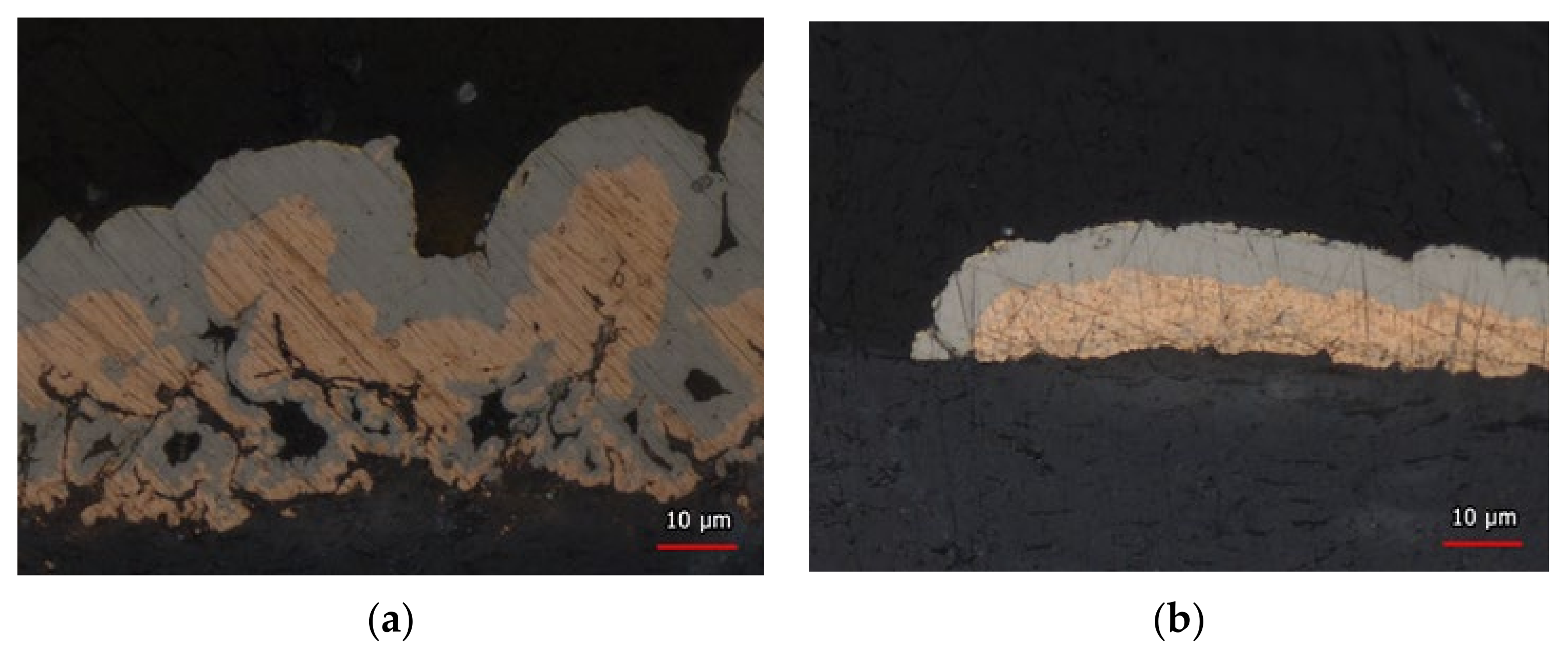
The FR4 (galv. NiAu) was used as reference. Test specimens with large-area metallization for the experiments were prepared. The thermoset and the PTFE substrate materials are specific high-frequency optimized PCB substrates. Both materials consist of a polymer matrix combined with glass fabric and ceramic fillers to adjust the dielectric, thermal and mechanical properties. The LCP and the PEEK materials, which are processable by injection molding, consist of the polymer matrix, a flaky mineral filler and a special copper-chrome spinel pigment that enables the subsequent electroless copper deposition after laser direct structuring. The known disadvantage of the LDS-processed materials are their high roughness, which is inherent to the method and also required to some extent to enhance adhesion between metallization and the substrate. All test specimens made of 3D-capable materials were prepared in plane shape (2D) to maintain the testability and comparability on the test benches used for the characterization. Cross sections of LCP1-NiAu and PEEK-NiAu are shown in Figure 2 indicating their high roughness.

2.2. Wire Bond Process

The thermosonic (TS) wire bonding process was performed on an F&K Delvotec G5 Wire Bonding System with a transducer bond frequency of 67 kHz. The system was equipped with the F&K Delvotec G5 62000 Gold Ball bond head. As bonding tool the capillary tube SI 35110 515E ZB76 for 25 µm gold wire from Small Precision Tools (SPT) and the 25 µm gold wire with a tensile strength of >9 cN from Heraeus were used.
The test specimens were mounted on a vacuum bracket and an electronic hot plate of the wire bonding system to control the temperatures. This setup was chosen to realize a higher contact pressure between bracket and substrate to eliminate movements during the bonding process. The hot plate was controlled to maintain similar thermal conditions for the bonding surfaces of all test specimens. For all substrates the surface temperature was adjusted to 140 °C. This temperature was selected to absorb thermal oscillation to prevent the assembly of a thermal downturn below 120 °C. The 120 °C bonding temperature is the suggested minimum value in the industry for a stable TS wire bonding [17].
With the reference substrate (FR4-Galv. NiAu) and according to the results of the pull tests to fulfil the DVS standard, the wire bonding processes with the parameters shown in Table 2 were developed.
The free-air ball was melted by arc flash for 25 ms with a current of 27 mA. With these parameters, the wire bonding process was performed on all test specimens. In addition to the standard wire bonding, a variation of stitch on ball was implemented on selected substrates with a high-roughness surface to improve bondability in terms of pull strength. Parameters such as the ball size and bonding force were changed in order to achieve the pull test limits of the DVS standard, as described later.

2.3. Thermal Observation of the Bond Surface

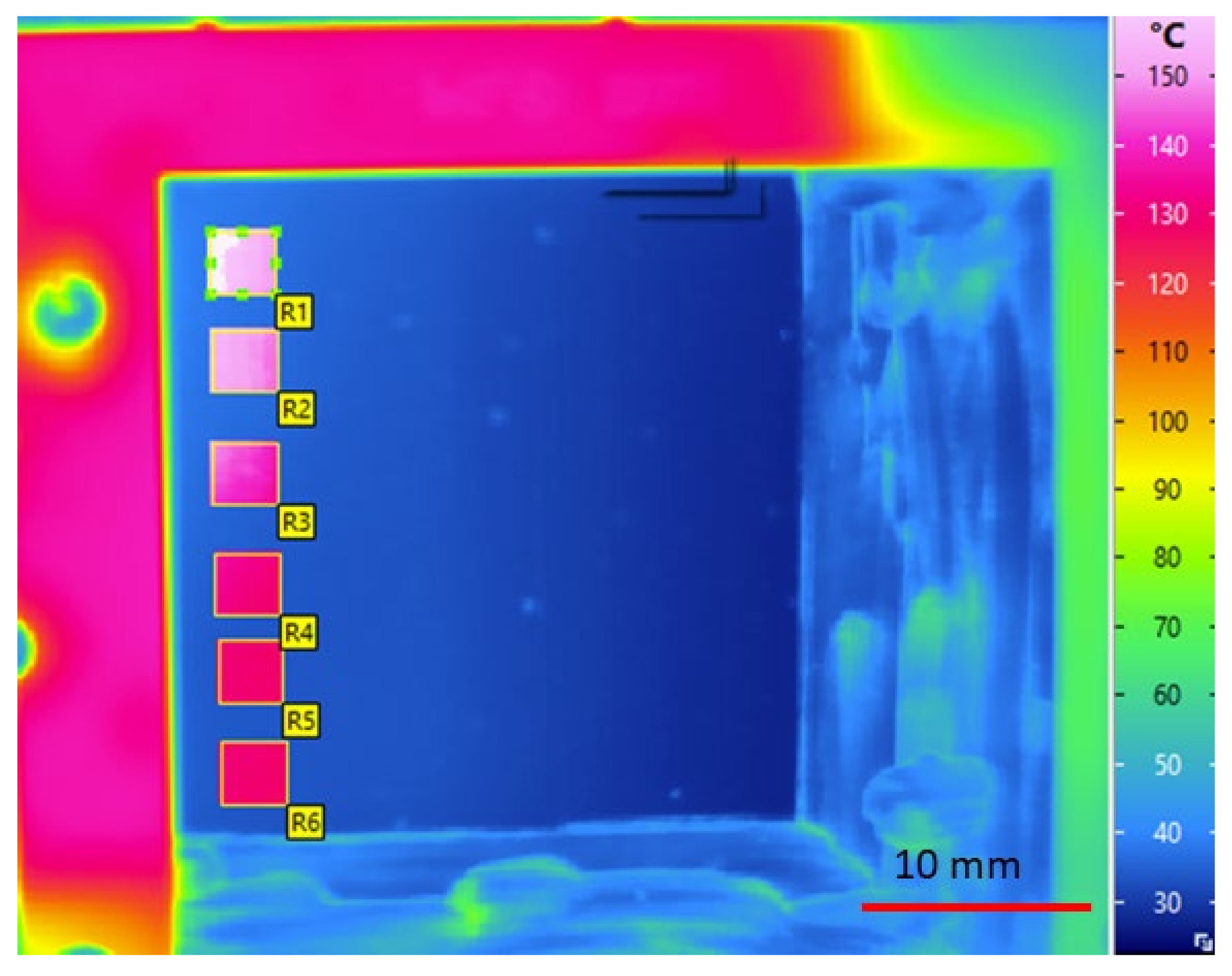
To control the thermal conditions of the test specimens, an infrared camera (InfraTec VarioCam HR Head, InfraTec, Dresden, Germany) in combination with the software “IRBIS 3.1 plus” was employed. A calibrated measurement range of 100 °C to 300 °C was selected. Before each measurement, the camera was calibrated at room temperature with closed objective to provide a basic measurement state of a black radiator. The camera was placed 20 cm above the test specimen in the workspace of the wire bonding system. A PTFE thermocouple (Datapaq) probe was used for calibration and finding emissivity values (ε) to measure the temperature by using its thermal radiation with the infrared camera. This way the bond surface temperatures for the different test specimens were equal to 140 °C independent of the thermal conductivity of the material to assure that the temperature of the bonding surface was above 120° according to the recommendation [17]. Measuring fields (Figure 3: R1 to R6) were defined to allocate the bond areas. Contact of the surface on the heated vacuum adapter was ensured. The camera was removed from the bonding area prior to executing the wire bonding process.

2.4. Bond Pad Surface Characterization

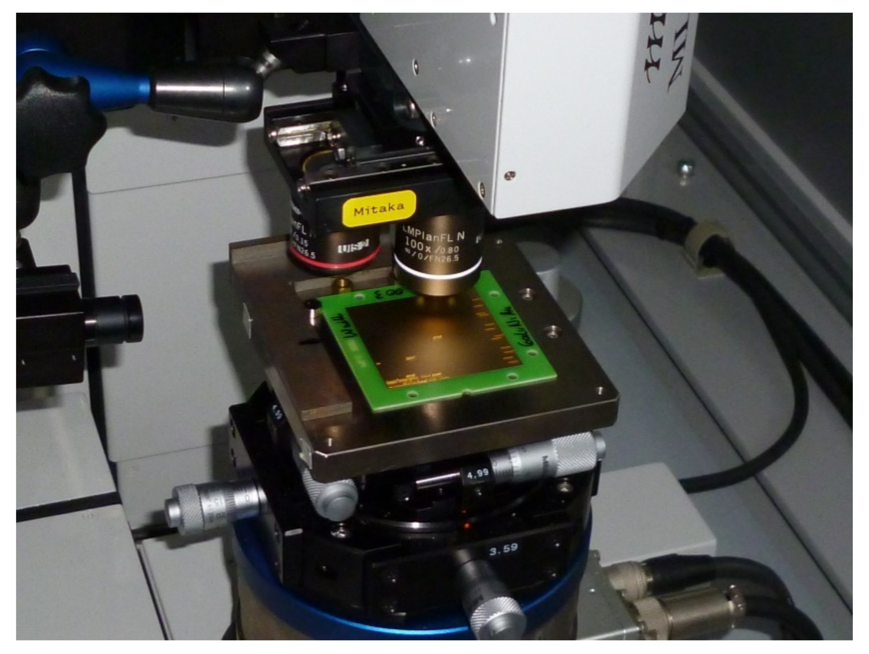
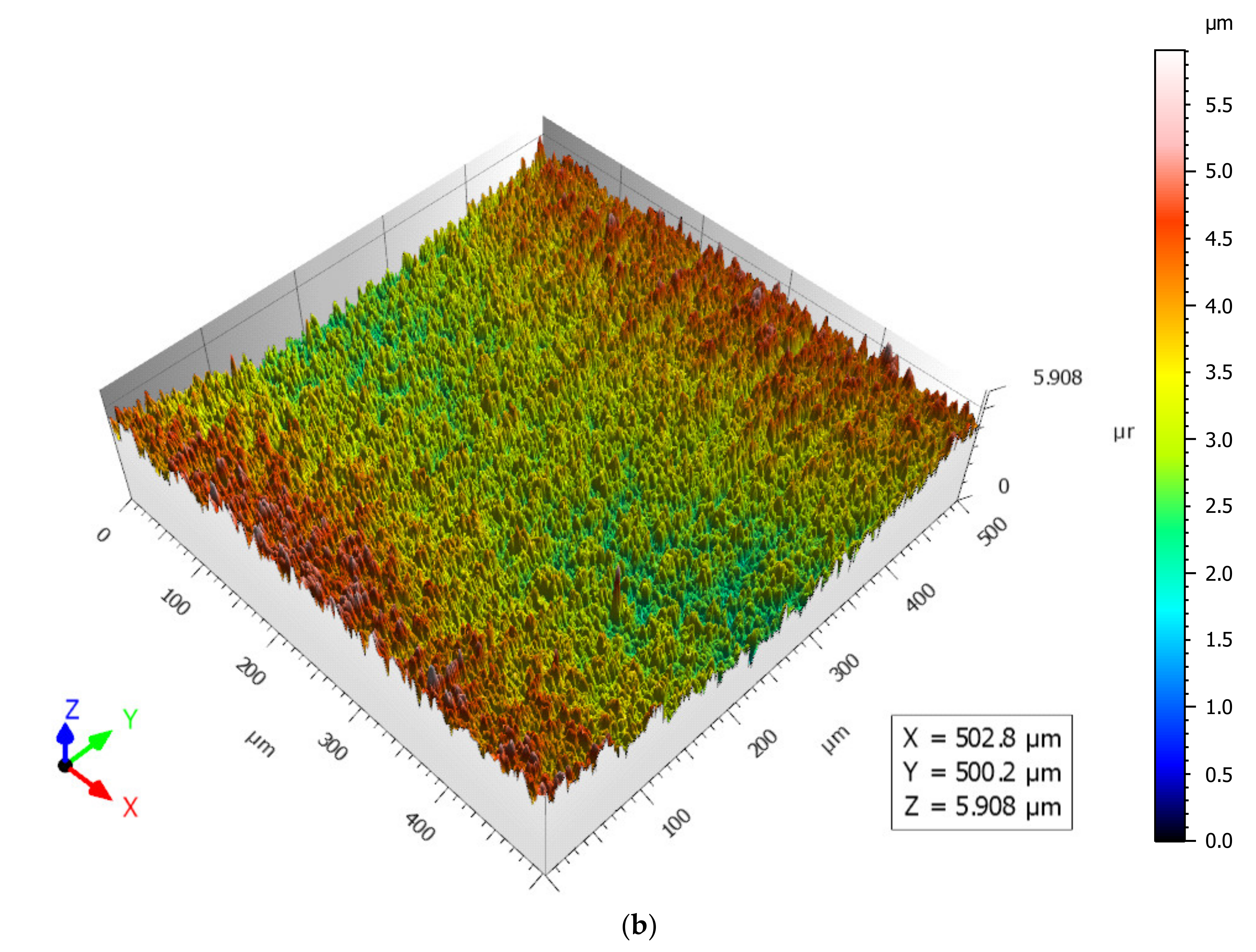
The roughness was measured by a 3D laserpoint autofocus scanner (Mitaka MLP-3); thus not only profile parameters but also surface parameters such as Sa, Sz and Sq were recorded. Those parameters, as an extension of Ra, Rq and Rz, were used to evaluate the surface roughness as they provide a deeper understanding of the surface structure than simple line scans. With the 3D laserpoint autofocus scanner the topographies of the test specimen surfaces were plotted (Figure 4). In the Mitaka control software the position of 12 measurement areas were defined on the bonding surfaces with a size of 500 µm × 500 µm. The measurements were performed with a resolution of 1 µm in the horizontal x–y directions and 10 nm in the z direction. Limiters at the left edge and top edge of the Mitaka bracket ensured that the test specimens were placed repeatedly at the same position. The 12 areas were measured automatically by a software macro. The analysis of the topographies was performed with the software Mitaka Map (Rev. 1.04). According to the DIN standards 25178 for surfaces and 4287 for profiles the following parameters were analysed:
  • Sa—Arithmetical mean height of the surface;
  • Sz—Maximum height of the surface;
  • Sq—Root mean square height of the surface;
  • Ra—Arithmetical mean deviation of the assessed profile;
  • Rq—Root mean squared;
  • Rz—Average Rz value over assessment length.

2.5. Characterization of Bond Strength in Means of Pull Tests

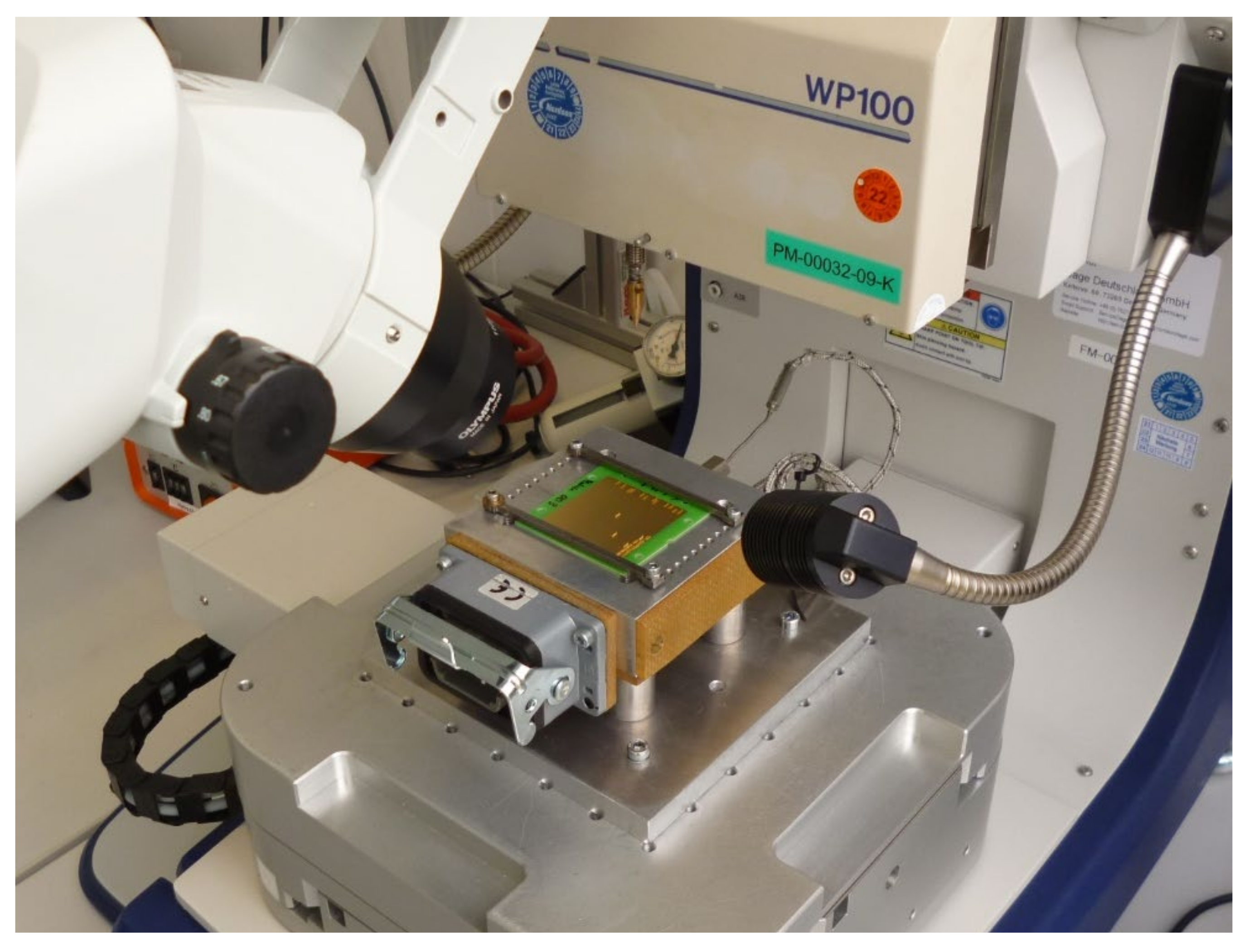
Wire bond characterization of ball–wedge bonding is typically performed by evaluating the shear force of the ball bond as well as a pull test to characterize the overall strength statistically. On rough surfaces, a shear test according to the standards cannot be performed reliably since the shear height differs, thus not allowing a consistent evaluation. Furthermore, mechanical blocking causes lateral forces to be recorded, which are not caused by the bond surface itself. However, due to the effects described in Section 1, the major quality issue when bonding on rough surfaces can be observed at the wedge bond, while no ball lift offs could be observed throughout the study. The wire pull test method according to standard DVS 2811 was utilized to examine the adhesion strength of the wire bonds. The pull tests consisted of 12 packages of 30 wire bonds with a 100 µm pitch in series on the bonding surfaces of the test specimens each at a different position. Every single wire bond was designed with a distance from ball to wedge of 800 µm and a loop height of 200 µm. The pull tests were performed on the Dage 4000 plus system with the pull test cartridge WP100 and a 70 µm diameter hook tool from Nordsen (Figure 5). With the software “Paragon” from Nordsen, the pull tests resultant forces and pull heights were recorded and the damage codes investigated. With these results, the tensile strength of each bond was calculated.

3. Results

3.1. Surface Roughness of Bond Pad Surface Characterization

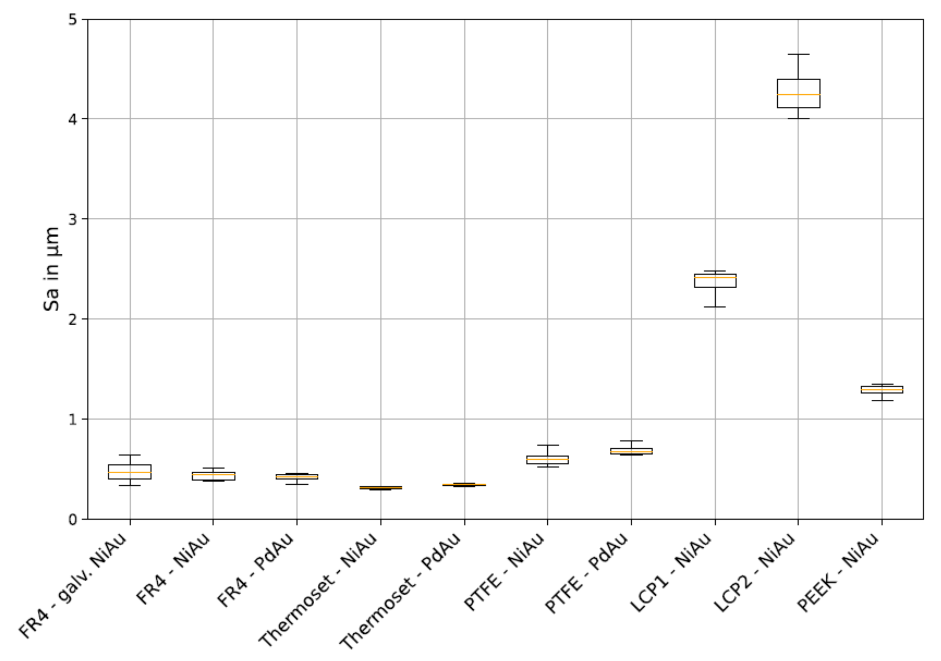
The mean surface roughness values of Sa, Sq, Sz, Ra, Rq and Rz were calculated with the Mitaka Map Analyse Software by the topographic measurements (with 12 bonding areas of each probe) as described in Section 2, “Bond Pad Surface Characterization”. The mean values and the associated standard deviations for the different substrate groups are shown in Table 3. This is also illustrated by the standard deviations in Figure 6.
Significant differences were noted between the substrates. All substrates used for 3D applications (LCP and PEEK) showed very high roughness. Furthermore, large variations in roughness with LCP and PEEK prevailed, while low roughness variations on FR4 as a reference and most of the other materials were observed. It is noticeable that for LCP 1 the Sa value was lower than for LCP 2, while with Sz was higher. Especially on LCP1 (NiAu), shown in Figure 7a, a larger number of surface peaks of sufficient height was observed compared to FR4 PdAu (Figure 7b). The values obtained with this measurement are evaluated in correlation to the bond strength later on.

3.2. Controlling of the Thermal Factor and Epsilon Determination

In order to adapt the surface temperature of each substrate to the recommended value, the set hot plate temperature requires adaptations. Therefore, the thermal camera was calibrated. The mean values and standard deviations of the epsilon measurement areas are shown in Table 4 for each substrate. The adapted settings for compensating the convection of the surface temperatures are also included in the table. The values are constantly above 120 °C.

3.3. Characterization by Pull Tests

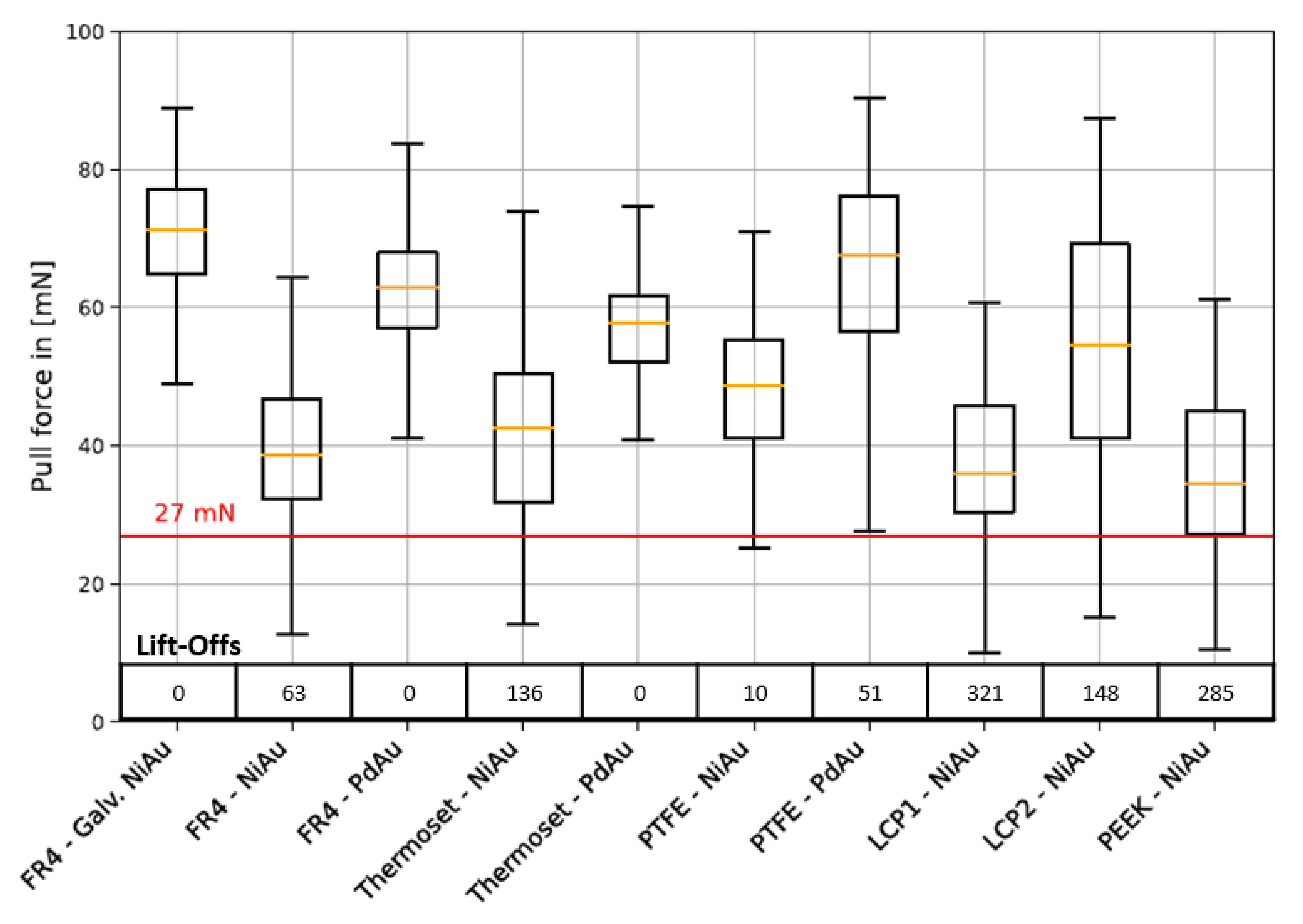
Mean pull bond strength values for the different substrates were calculated with their standard deviation. The values are illustrated in a boxplot (Figure 8). The DVS standard was fulfilled by FR4 Galv. NiAu, Thermoset PdAu and Fr4 PdAu. LCP 2 and PTFE PdAu showed tendencies of high mean pull strengths but also many outliers with low pull strengths and faulty bond connections. On Peek, LCP 1 and Fr4 NiAu the pull strength was very low and high numbers of lift-offs, and non-sticks occurred. Thermoset NiAu had a lower mean strength but at the same time outliers with very high pull strengths (>90 mN).

3.4. Substrate-Dependent Measurement of Roughness and Pull Force on LCP-MID

In order to relate the surface roughness to the pull force, the surface roughness was measured on two positions of the measurement fields R1 to R6 of the substrate with the maximum roughness (LCP 2, see also Figure 6 for average values and standard deviation). A total of 30 bonds were placed on each position. No correlation could be found. The coefficient of correlation was calculated as 0.0827.
Figure 9 shows the variations of the surface roughness on an LCP 2 substrate including the correlated pull strength of the bonds. The mean pull forces measured were 55.8 ± 5.4 mN on the different bond areas.

3.5. Improving Bondability by Means of Stitch-on-Ball Method

The lift-offs all took place in the wedge bond, whereas the ball had a good strength. Therefore, the so-called stitch-on-ball method was investigated. The method is a combination of the bonding process of stud bumps (safety balls) and standard ball–wedge (stitch) bonding. In the first process step, a stud bump is placed on the wedge (stitch) position of the standard bond process. In the second step, a standard bond process is performed, whereas the wedge (stitch) is bonded on the stud bump. Parameters such as ball size, US-Power, -Time and -Force were adapted in order to achieve good results.
The improvement adaptation steps of the bonding parameters on LCP 2 (Vectra E840i) are shown in Figure 10. The percentage of the numbers of the pull test of the average pull strength were considered with a pull strength above/below 27 mN and the percentage standard deviation above/below 15%. The first column “Standard” shows the initial situation using the standard ball bonding parameter; from step 1 to step 7 the bonding parameters were changed to improve the pull test results.
At the initial step, a strong adaption of the major bonding parameter US-Time (80 ms to 300 ms), US-Power (120 digits to 110 digits) and Bond Force (25 cF to 40 cF) of the bond balls and the safety balls. Because there were no non-sticks or lift-offs of the bond and safety balls these parameters for the ball bondings were retained during further improvement steps. At the second adaptation, the wedge parameters were changed. US-Time (30 ms to 60 ms), US-Power (200 digits to 110 digits) and Bond Force (15 cF to 40 cF). The third and fourth reduced the ball bond size from 25 ms flame-off time to 18 ms. In step five the wedge parameters were maintained to observe if there is a significant change in the pull test quality by an alternative bonding position. In step six the wedge parameters US-Time (60 ms to 80 ms), US-Power (110 digits to 120 digits) and Bond Force (40 cF to 15 cF) were further adapted. Finally, only the US-Time (80 ms to 100 ms) was changed, proving the adaption of the bonding parameters successful.
The method showed significant improvement of bondability, thus fulfilling the DVS pull test standard. Figure 11 shows a stitch-on-ball connection after the pull test. The connection was broken at the wire heel, whereas the ball and wedge were still intact.

4. Discussion

The general statement that lower surface roughness leads to higher bond strength could not be confirmed within this study. No significant correlation was found between surface roughness and bond strength by pull testing. However, surface defects such as spikes of sufficient height markedly impacted the performance of single bonds. Consequently, the lower pull strength obtained by bonds on rougher substrates, such as LCP, confirms the reduction in bond formation due to high spikes when compared to the other tested substrates. The pull tests and the failure of individual bonds also suggest that the density of spikes has a crucial impact on bondability.
Comparing the surface roughness and pull strengths of the two different LCP probes in Table 5 supports this thesis. While LCP1, with lower Sa values, shows lower mean and standard variation of pull strengths, it also has many more lift-offs. LCP2, with a higher Sa, shows a lower density of spikes and a higher bond quality, although the standard deviation is higher.
The reason for such effects can be found in the methods of how surface roughness values were obtained in contrast to the shear force, which is transferred to the wedge during bonding. Ra presents an average value and is insensitive to profile spikes and valleys. Rz also presents an arithmetic median of the absolute values of the heights of the five highest profile peaks along a defined length. Sz defines the sum of the largest peak height and the largest pit value within a defined area, thus only giving a single spike value. Neither Sa nor Rq provide any information about the density of spikes. Once the density is high enough, the plateau of spikes allows energy transfer for bonding without geometric obstruction due to higher spikes in the circumference of the bond capillary. Conclusively, defining the spike density may be a better parameter for quality reasons regarding the limits of bondability on rough surfaces. However, such a plateau surface for bondability depend on many factors such as hardness of the pad material, energy level and thus softness of the wedge material, elastic behavior of the underlying substrate, in particular when higher thermal energy needs to be applied to achieve a sufficient temperature on the pad surface due to low thermal conductivity.
Another observation was that, when comparing mean surface roughness and tensile forces, different substrate materials with similar roughness showed significant differences in bondability., e.g., PTFE bondability is lower than PCB bondability although the roughness is similar. This confirms the assumption, that the mechanical properties of the overall composites are a major factor. Moreover, when comparing the two PTFE probes. the rather soft substrate material shows better properties regarding bondability with the NiAu-finish than with the PdAu, since Nickel counteracts as a brittle/hard material, thus improving energy transfer and thus bondability.
The issue of varying surface parameters across the substrates leads to another challenge: improvement of the surfaces may improve the bond quality but is very difficult to control in terms of process stability. This is due to material variations, mold flow and thus the orientation of fibers, fillers and molecules, laser parameters and reactivity of the autocatalytic electrolytes, and many more factors. Consequently, optimizing the bonding strategies including raising efforts to achieve sufficient results may be a valid option.
Tuning the bonding parameters showed that the influence of surface roughness is tolerable within a certain range. To overcome this issue, a stitch-on-ball strategy was used. As was observed, the method could enable bondability on those substrates, for which bonding parameters cannot be adapted sufficiently. While not investigated in detail within this study, it can be assumed that this is due to mechanical interlocking or bond welding due to the higher bond forces of the ball bonding during the process.
In order to combine the advantages of HF materials and 3D structuring, the surface properties of the 3D materials should be specifically adapted if wire bonding is a required step within the process chain. Options include optimizing the metallization composition and thickness of specific layers for the density of spikes. Furthermore, adjusting transducer frequencies to material composites can enhance the energy uptake from ultrasound power and facilitate the transfer of bond force to improve the reliability of the bonds [18]. However, when optimizing the composite system towards reduced surface roughness and varying the LDS process, care needs to be taken to not lower the reliability of the substrate/metal adhesion. In addition, other effects such as crack development in conductive tracks, corrosion tracks or parts by unsuitable matching of metals during the assembly or diffusion and thus the development of instable intermetallic phases need to be considered.

5. Summary

In this paper, the topographies of different metallization and substrate materials for HF applications, such as LCP, PEEK and PTFE polymers and thermosets, were investigated regarding their bondability. For that purpose, the surface temperatures were matched up, surface roughness measured and bond parameters found and compared with the state of the art. No correlation was found regarding surface roughness and pull strength. Furthermore, the systematic analysis allows the first insight that the main factor decreasing the bond quality is based on the density of spikes and the plateau being formed to provide stable wedge bonding. Exceeding a specific, yet not quantified, height on rougher substrates leads to more failures and hence deteriorates bondability. Due to the complexity of multiple factors, further experiments are required to provide quantitative results for the indicated effects. The results suggest that the tuning of bonding parameters allows for a far larger process window for substrate manufacturing and metallization regarding the required surface roughness. The bonding strategy with the stitch-on-ball method still allows the employment of such substrates within the required specification for reliable use under certain circumstances.

Author Contributions

Conceptualization, T.G.; methodology, T.G., K.W. and E.M.; investigation, E.M.; resources M.W. and T.G.; data curation, E.M.; writing—original draft preparation, K.W. and M.W.; writing—review and editing, T.G.; visualization, E.M.; supervision, T.G.; funding acquisition, T.G. and A.Z. All authors have read and agreed to the published version of the manuscript.

Funding

This research was funded by Deutsche Forschungsgemeinschaft (DFG), under grant number 386746281.

Data Availability Statement

All data used are shown in the text. Raw data are available on request.

Acknowledgments

The authors would like to acknowledge the support of the DFG.

Conflicts of Interest

The authors declare no conflict of interest.

References

  1. Bogatin, E. Roadmaps of Packaging Technology; Addie Rose Press: Longmont, CO, USA, 2018. [Google Scholar]
  2. Tummala, R.R. Fundamentals of Microsystems Packaging, 1st ed.; McGraw-Hill Education: New York, NY, USA, 2001. [Google Scholar]
  3. Hall, E.; Lyons, A.M.; Weld, J.D. Gold wire bonding onto flexible polymeric substrates. IEEE Trans. Compon. Packag. Manuf. Technol. Part A 1996, 19, 12–17. [Google Scholar] [CrossRef]
  4. Cullen, D.; Kline, B.; Moderhock, G.; Gatewood, L. Effects of surface finish on high frequency signal loss using various substrate materials. CIRCUITREE-CAMPBELL 2001, 14, 80. [Google Scholar]
  5. Franke, J. Räumliche Elektronische Baugruppen (3D-MID)—Werkstoffe, Herstellung, Montage und Anwendungen für Spritzgegossene Schaltungsträger, 1st ed.; Carl Hanser Verlag: Munich, Germany, 2013. [Google Scholar]
  6. Geneiß, V.; Lüke, T.; Hedayat, C.; Wolf, M.; Janek, J.; Meißner, T.; Barth, M.; Eberhardt, W.; Zimmermann, A.; Otto, T. Impedance-Controlled Design and Connection Technology for Micromounting and Hybrid Integration of High-Frequency and Mixed-Signal Systems with MID Technology. In Proceedings of the 2018 Smart Systems Integration, Dresden, Germany, 11–12 April 2018. [Google Scholar]
  7. Friedrich, A.; Fengler, M.; Geck, B. LDS Molded Interconnect Devices Fit for mmWave. Microw. J. 2016, 59, 116–128. [Google Scholar]
  8. Buckmüller, P.; Eberhardt, W.; Kessler, U.; Willeck, H.; Kück, H. Aluminium wedge-wedge wire bonding on thermoplastic substrates made by LPKF-LDS® technology. In Proceedings of the 3rd Electronics System Integration Technology Conference ESTC, Berlin, Germany, 13–16 September 2010; pp. 1–5. [Google Scholar]
  9. Kanthamneni, A.; Brose, A.; Majcherek, S.; Brinkhues, S.; Aman, A.; Schmidt, B. Characterization of Ultrasonic Wire Bonding for LDS MID Prototyping. IEEE Trans. Compon. Packag. Manuf. Technol. 2016, 6, 1703–1710. [Google Scholar] [CrossRef]
  10. Scholz, U. Untersuchungen zur Eignung des Ultraschallbondens für Die Chipmontage auf MID-Substraten. Ph.D. Thesis, University of Stuttgart, Stuttgart, Germany, 2003. [Google Scholar]
  11. Lai, Z.; Liu, J. The Nordic Electronics Packaging Guideline. Microelectron. Int. 2000, 17. [Google Scholar] [CrossRef]
  12. Kologe, J. High Reliability Wire Bond Technique for MIDs. Available online: https://www.3d-mid.de/wp-content/uploads/2019/10/Kologe_J._-_High_Reliability_Wire_Bond_Technique_for_MIDs.pdf (accessed on 10 November 2021).
  13. Wu, Y.; Long, Z.; Han, L.; Zhong, J. Temperature effect in thermosonic wire bonding. Trans. Nonferrous Met. Soc. China 2006, 16, 618–622. [Google Scholar] [CrossRef]
  14. Liang, Z.N.; Kuper, F.G.; Chen, M.S. A concept to relate wire bonding parameters to bondability and ball bond reliability. Micro-Electron. J. 1998, 38, 1278–1291. [Google Scholar] [CrossRef]
  15. Charles, H.K. Advanced Wire Bonding Technology: Materials, Methods, and Testing. In Materials for Advanced Packaging; Lu, D., Wong, C.P., Eds.; Springer: New York, NY, USA, 2017. [Google Scholar]
  16. Test Procedures for Wire Bonded Joints; Technical Bulletin DVS 2811; DVS Media GmbH: Düsseldorf, Germany, 2017.
  17. Cosemi—Wire-Bonding-Guidelines; Application Note AN1002; Cosemi: Irvine, CA, USA, 2016.
  18. Sedlmair, J.; Nacke, U. Technische Notiz 2015/02; F&K Delvotec Bondtechnik GmbH: Ottobrunn, Germany, 2015; Available online: https://www.fkdelvotec.com/fileadmin/media_fuk/dokumente/160809D_TN_15_01_Frequenz.pdf (accessed on 10 November 2021).
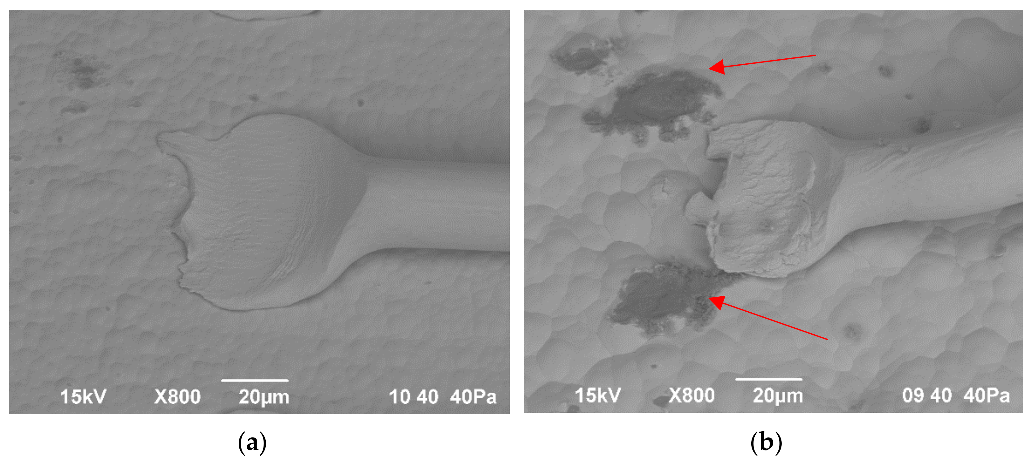
Figure 1. Wedge bond on FR4 Galv. NiAu (a) and LCP2 (b) peaks of roughness impede the wedge process by geometrically blocking the capillary.
Jmmp 06 00009 g001
Figure 2. Cross section of LCP1-NiAu (a) and PEEK-NiAu (b).
Jmmp 06 00009 g002
Figure 3. Infrared camera shot of FR4-PdAu at approximately 140 °C.
Jmmp 06 00009 g003
Figure 4. Topographic measurements by Mitaka MLP-3.
Jmmp 06 00009 g004
Figure 5. Test setup for pull tests by Nordsen DAGE 4000 plus.
Jmmp 06 00009 g005
Figure 6. Boxplot arithmetic mean height Sa/µm of all probes.
Jmmp 06 00009 g006
Figure 7. Image of bond pad surface on LCP 2 NiAu (a) and on standard FR4 PdAu (b) measured by Mitaka MLP-3.
Jmmp 06 00009 g007aJmmp 06 00009 g007b
Figure 8. Pull test boxplot of all probes.
Jmmp 06 00009 g008
Figure 9. Variations of surface roughness with the according average pull strength of the bonds on LCP 2 substrate.
Jmmp 06 00009 g009
Figure 10. Stitch-on-bump improvement evolution by adaption of the bonding parameters.
Jmmp 06 00009 g010
Figure 11. Bond connection with stitch-on-ball method after pull testing.
Jmmp 06 00009 g011
Table 1. Bonding substrate and material combinations.
IdentificationSubstrate MaterialMetallizationSuitability (3D/HF)
FR4-Galv. NiAuFR4NiAu-
FR4-NiAuFR4NiAu -
FR4-PdAuFR4PdAu-
Thermoset-NiAuRogers RO4350bNiAuHF
Thermoset-PdAuRogers RO4350bPdAuHF
PTFE-NiAuTSM-DS3NiAuHF
PTFE-PdAuTSM-DS3PdAuHF
LCP1-NiAuTecacomp LCP LDS black 4107Autocatalytic NiAu3D/HF
LCP2-NiAuVectra E840i LDSAutocatalytic NiAu3D/HF
PEEK-NiAuTecacomp PEEK LDS black 1047045Autocatalytic NiAu3D/HF
Table 2. Bonding parameters developed with reference substrate.
Bonding ParameterBallWedge
Ultrasonic Time—UT80 ms80 ms
Ultrasonic Power—UP120 digits120 digits
Bond Force—BF25 cN15 cN
Temperature of Bond surface140 °C140 °C
Table 3. Surface roughness in µm values of bond areas.
SubstrateSA
in µm
SQ
in µm
SZ
in µm
RA
in µm
RQ
in µm
RZ
in µm
FR4-Galv. NiAu0.48 ± 0.10.58 ± 0.116.74 ± 2.640.27 ± 0.040.34 ± 0.041.82 ± 0.32
FR4-NiAu0.44 ± 0.050.55 ± 0.066.89 ± 1.80.30 ± 0.060.39 ± 0.132.22 ± 1.07
FR4-PdAu0.41 ± 0.040.52 ± 0.046.79 ± 3.150.25 ± 0.030.32 ± 0.031.65 ± 0.16
Thermoset-NiAu0.31 ± 0.020.42 ± 0.028.23 ± 4.760.25 ± 0.040.31 ± 0.051.68 ± 0.20
Thermoset-PdAu0.34 ± 0.020.45 ± 0.037.70 ± 3.170.28 ± 0.060.35 ± 0.081.93 ± 0.43
PTFE-NiAu0.60 ± 0.060.76 ± 0.089.37 ± 2.970.46 ± 0.070.59 ± 0.093.37 ± 0.75
PTFE-PdAu0.69 ± 0.050.87 ± 0.0610.36 ± 2.220.53 ± 0.060.70 ± 0.174.10 ± 1.81
LCP1-NiAu2.38 ± 0.153.35 ± 0.1970.15 ± 21.971.94 ± 0.542.50 ± 0.6312.90 ± 2.30
LCP2-NiAu4.27 ± 0.21 5.63 ± 0.2760.42 ± 6.303.96 ± 0.715.10 ± 0.9325.03 ± 4.78
PEEK-NiAu1.38 ± 0.34 2.23 ± 1.2747.15 ± 19.101.12 ± 0.231.51 ± 0.358.31 ± 2.11
Table 4. Empirical values of epsilon determination and adapted surface temperatures.
SubstrateFR4 Galv. NiAuFR4 NiAu1FR4 PdAuThermoset NiAuThermoset PdAuPTFE NiAuPTFE PdAuLCP 1 NiAuLCP 2 NiAuPEEK NiAu
Emissivity ε 0.0690.1030.1000.1060.1040.0950.0950.0560.0600.062
ε-St.Dev.-R60.0130.0090.0080.0100.0080.0070.0040.0010.0020.003
Calibration T of Heating Plate Temperature/°C145145145145145145145145145145
Adapted bonding T of HP180 °C178171170170158162161160158
Table 5. Comparison of surface roughness (in µm) and pull strengths (in mN) of bonds on different LCP substrates.
SubstrateSa
in µm
Sz
in µm
Ra
in µm
Rq
in µm
Rz
in µm
Pull Mean
in mN
Lift-Offs
LCP12.38 ± 0.1570.15 ± 21.971.94 ± 0.542.50 ± 0.6312.90 ± 2.341.7 ± 9.8321
LCP24.27 ± 0.2160.42 ± 6.33.96 ± 0.715.10 ± 0.9325.03 ± 4.7859.8 ± 16.2148
Publisher’s Note: MDPI stays neutral with regard to jurisdictional claims in published maps and institutional affiliations.