Article

Microstructure and Mechanical Properties of Ti-6Al-4V Additively Manufactured by Electron Beam Melting with 3D Part Nesting and Powder Reuse Influences

1
National Research Council Canada, Aerospace Research Center, Montreal, QC H3T 1J4, Canada
2
McGill University, Department of Mining and Materials Engineering, Montreal, QC H3A 0C5, Canada
3
Department of National Defence, Directorate of Technical Airworthiness and Engineering Support (DTAES), Ottawa, ON K1A 0K7, Canada
*
Author to whom correspondence should be addressed.
J. Manuf. Mater. Process. 2022, 6(1), 21; https://doi.org/10.3390/jmmp6010021
Submission received: 7 December 2021 / Revised: 20 January 2022 / Accepted: 20 January 2022 / Published: 1 February 2022
(This article belongs to the Special Issue Advances in Metal Additive Manufacturing/3D Printing)

Abstract

:
To better support the transition to more industrial uses of additive manufacturing, this study examined the use of an Arcam Q20+ industrial 3D printer for producing heavily nested Ti-6Al-4V parts with both in-specification (IS) and out of specification (OS) oxygen content in reused grade 5 powder chemistries. Both the OS and IS powder chemistries were evaluated to understand their impact on build integrity and on static and fatigue performance. The results from our evaluations showed that controlling the bed preheat temperature in the Q20+ to relatively low values (326–556 °C) was effective in limiting microstructural coarsening during the long build time and enabled adequate/balanced performance vis à vis the tensile strength and ductility. Overall, the tensile properties of the IS Ti-6Al-4V material in the as-built and machined states fully met the requirements of ASTM F2924-14. By contrast, the ductility was compromised at oxygen levels above 0.2 wt.% (OS) in Ti-6Al-4V produced by EBM. Removal of the surface layer by machining increased the consistency and performance of the IS and OS Ti-6Al-4V materials. The fatigue behaviour of the EBM Ti-6Al-4V material was in the range of properties produced by casting. Due to the strong influence of both the surface finish and oxygen content on the fatigue strength, the IS Ti-6Al-4V material exhibited the highest performance, with results that were in the range of parts that had been cast plus hot isostatically pressed.

1. Introduction

The current era of Industry 4.0 is marked by a manufacturing renaissance, with engineers and professionals learning and applying digital technologies to transition production from conventional subtractive manufacturing to additive manufacturing (AM), which is a disruptive technology for enabling production in a layer-by-layer manner, using advanced materials and/or alloys [1,2,3,4,5,6]. For metal AM, the different platforms are based on powder bed fusion (PBF) and direct energy deposition (DED) technologies that involve using a heat source (e.g., arc, laser, or electron beam) to melt powder or wire feedstock [7]. Of these, PBF processes have been the focus of technology developments, specifically for complex geometry net shape small parts, and these processes have evolved rapidly and matured sufficiently to deliberate introduction into new aircraft designs, as well as retrofits for functional applications, which are beyond the tooling, prototyping, or development of components [8,9,10].
Amongst the broad range of metallic materials used in aerospace structures, titanium (Ti) alloys remain strategic, both from the perspective as a substitution material to replace high strength alloys in legacy aircraft and as a compatible material for use with composites in new aircraft designs. However, Ti alloys are notorious for their manufacturing challenges, due most notably to their high reactivity during processing at elevated temperatures. Historically, this has lowered the economic driver for selecting Ti alloys when using conventional technologies based on subtractive manufacturing. Here, it is important to mention that the buy-to-fly ratios of aerospace parts are high (roughly 9:1) and though there may be future opportunities to recycle the contaminated and inhomogeneous swarf from subtractive processing, presently these costly scrapped chips are downgraded to ferrotitanium production [11]. Thus, Ti alloys are prime candidates for sustainable smart manufacturing via AM routes.
Unsurprisingly, there has been avid research interest in benchmarking AM of Ti alloys, most prominently Ti-6Al-4V, the alpha-beta (α-β) workhorse grade in the industry [12,13,14,15,16]. Recent research studies on AM of Ti-6Al-4V have focused on advanced testing methods to characterize several different aspects of this alloy’s behaviour including among others, the creep behaviour [17,18], the vibration fatigue behaviour [19,20], and the fatigue crack growth performance [21]. Based on this flurry of research, the processing influences on the performance of AM Ti-6Al-4V are evident and the scatter in the properties are concerning from the point of view of scaling this technology for producing components certified for use in aerospace.
Thus, to address the safe exploitation of Ti-6Al-4V–in tertiary, secondary, and, most critically, primary structures–requires the benchmarking of properties that are truly representative of the final AM part. Therefore, unlike previous studies that have typically focused on laboratory-scale trials, the present research targeted developing AM of Ti-6Al-4V for industrial production and qualification of aerospace parts. An important parameter considered in the present study for cost-competitive production of complex geometry Ti-6Al-4V parts was the build volume capacity.
To date, the research in EBM of Ti-6Al-4V has been limited to two-dimensional (2D) arrangements of coupons with small build volumes (i.e., greater surface than volume) for the generation of mechanical properties. Three-dimensional (3D) part nesting in high-volume serial production of small parts and/or 3D printing of large parts—that have a greater volume than surfaces—lead to long and continuous build times, which pose challenges for thermal management and possible microstructure evolution. Furthermore, with the need to understand on-demand manufacturing in extreme conditions, such as on a battlefield, new paradigms must be studied, such as the as-built characteristics for operations after limited (or no) post-processing, as well as possible gains in the performance through surface finishing improvements. The role of powder composition—notably the oxygen content—must also be understood to predict the mechanical properties of the final part and benchmark the design of allowable limits for safe-life specifications in such extreme conditions. In this work, the production of nested Ti-6Al-4V coupons using an ARCAM Q20+ industrial 3D printer and their resulting characteristics, including density, microstructure, and properties (hardness, tensile, and fatigue), were studied. A key aspect of this study is the nesting/stacking of the coupons/parts, which led to a prolonged and continuous building time of 225 h and 49 min.

2. Materials and Methods

The feedstock material used in this research was plasma atomized grade 5 Ti-6Al-4V powder obtained from Advanced Powders and Coatings (AP&C) in Canada. To investigate the effect of minor oxygen contamination on mechanical properties of EBM-built coupons, two batches of recycled powder samples were used. The chemical composition of each batch of powders was measured with a LECO ON736 (St. Joseph, MI, USA) system and is shown in Table 1. The first batch of powders had an oxygen content of 0.27%, exceeding the 0.2% limit specified in the ASTM F2924-14 [22] standard for PBF built Ti-6Al-4V parts. A high oxygen composition was of interest, since one of the major objectives of these samples was to investigate the detrimental effects of using out-of-specification powders, a problem that can occur under austere situations, such as those sometimes found in expeditionary military applications. The second batch of powder was within grade 5 specification (see Table 1) and thus used for direct comparison. Hereafter, the first and second batch powders and their corresponding manufactured coupons are labelled and described as out-of-specification (OS) and in-specification (IS), respectively.
The powder morphology and microstructure were investigated using a Hitachi SU-3500 (Fukuoka, Japan) scanning electron microscope (SEM) and a Keyence VK-X (Osaka, Japan) laser scanning confocal (LSC) optical microscope (OM). Figure 1 shows the morphology of the powders used in this study. The powders were mostly spherical with few satellite particles attached. Internal porosity within some powder particles was observed, as seen in Figure 1b, and measured to be 0.4 ± 0.5% by optical methods. In addition, powder characteristics were investigated using a Horiba LA-920 (Kyoto, Japan) laser scattering particle size distribution (PSD) analyser and the results are shown in Figure 2, along with Hall flow and apparent density measurements (Hall Funnel, Qualtech Products Industry-HFM1800SS, Denver, CO, USA). PSD analysis and SEM measurements (data from roughly 50 particles) were consistent with one another. The powders had a mean diameter of 72 ± 2 μm.
The CAD build layout, as shown in Figure 3 with the support structures highlighted in blue, was printed with the OS and IS powder lots. This layout was designed to realize a packing density of 37% of the Q20+ build volume, to evaluate/validate the capability of vertical stacking and 3D nesting of small parts in one production run. The coupons were separated by lower density supports having a block design, which was selected as a balance between geometric stability and removal ease. After EBM, these supports were removed manually using simple hand tools, emulating expeditionary operations where availability of material removal technologies, such as the commonly used wire electro-discharge machining (EDM), would be, at best, limited.
Printing was undertaken with an Arcam Q20+ (Gothenburg, Sweden) EBM machine that utilized predefined parameter sets (called “Material Themes”). For Ti-6Al-4V the “Ti6Al4V_Q20-Preheat-5.0.40” and “Ti6Al4V_Q20-Melt-5.0.40” material themes were used for preheating the bed and melting each layer of powder, respectively, with a layer thickness set at 90 µm. For the printing of the support structures, the Arcam Material Theme “Ti6Al4V_Q20-Wafer-5.0.40” was employed. The vacuum chamber pressure was maintained at 4 × 10⁻³ mbar (0.4 Pa) with a partial pressure of helium (as a regulating gas to prevent powder charging). The monitored powder bed temperature remained within the range of 326 °C to 556 °C. The present study details the results obtained from the evaluation of three test specimen types: TD (tensile), FD (fatigue), and C (density, metallography, and hardness). The geometry and dimensional details of these test specimens are illustrated in Figure 3b. The tested TD and FD specimens were all built along the Z-axis.
To evaluate the build uniformity, C-type coupons from five different locations were selected to investigate the effect of build height on the density, microstructure, and Vickers hardness. Cubes labelled C2, C10, C30, C40, and C70 were selected. Their corresponding build heights, measured from the build platform, were roughly 20, 70, 210, 260, and 360 mm, respectively. Optical density analysis using metallography and image analysis software was undertaken in the XY, XZ, and YZ planes. Each coupon plane was mounted in conductive Bakelite followed by automated grinding down to 1200-grit and polishing (with 9 µm diamond and then 0.02 µm silica suspensions) to a mirror surface finish. Specimens were also chemically etched for microstructural examination using Kroll’s etchant, consisting of 2 mL HF, 10 mL HNO3, and 88 mL H2O. All metallographic investigations were conducted using a Keyence VK-X LSC OM. Vickers micro-hardness testing was performed on all three orthogonal (XY, YZ, and XZ) polished surfaces using a Struers DuraScan 80 machine (Ballerup, Denmark). Multiple hardness profiles were taken across the surfaces using a load of 500 g with a dwell time of 15 s according to the standard hardness procedures in ASTM E384 [23].
The surface roughness of the specimens to be used for tensile and fatigue testing, in both the as-built and the machined conditions, were measured to allow for later correlation with mechanical properties. Surface roughness measurements were performed according to the ISO 25178 [24] standard. The tensile specimens were tested at room temperature using an MTS 810 (Eden Prairie, MN, USA) machine—having a load capacity of 250 kN, a closed-loop servo hydraulic power supply with computerized control and equipped with mechanical and laser extensometers. Following the principles given in ASTM E8M [25], tensile tests were conducted until rupture using displacement control at a rate of 0.125 mm·min−1, which corresponds to an average strain rate of 0.005 min−1. The properties evaluated included the yield strength (YS), ultimate tensile strength (UTS), and percent elongation (EL). A minimum of five tensile specimens in each condition were tested to calculate the average reported properties.
The fatigue testing campaign for the coupons in the as-built and machined surface conditions was conducted according to the ASTM E466 [26] standard for load-controlled constant amplitude axial fatigue. Fatigue tests were performed up to failure at room temperature using a 250 kN MTS servo hydraulic testing system under load control with MTS series 647 (Eden Prairie, MN, USA) hydraulic wedge grips. Sinusoidal loading with a frequency of 6 Hz and a load ratio of R = 0.1 were applied in the fatigue tests. The fracture surfaces and cross-sectional fracture micrographs were investigated post-tensile and post-fatigue testing using SEM and OM, respectively.

3. Results and Discussion

3.1. Chemical Analysis Post-Fabrication

After EBM, the chemical compositions of the bulk Ti-6Al-4V in the OS and IS materials were analysed and the results are given in Table 2. The chemistry of the IS coupons conformed to the specifications in ASTM F2924 [22]. As intended, the oxygen content in the bulk Ti-6Al-4V material of the OS coupons exceeded the 0.20% limit, owing to its higher level in the feedstock powder. Compared to the oxygen content in the powder feedstock materials, the as-built Ti-6Al-4V material had higher oxygen levels in the OS (increase from 0.27% to 0.29%) and IS (increase from 0.18% to 0.19%) coupons, both likely due to oxygen pick up during EBM processing. Additionally, the Al content in the as-built Ti-6Al-4V coupons decreased by about 0.86 wt.%, relative to that in powder feedstock, which can be attributed to Al evaporation during the EBM process. These findings are in good agreement with those reported previously by Lu et al. [27] using an Arcam A2 system.

3.2. Density in as-Built Condition

The density of the two coupon types (OS and IS) were investigated using optical methods. Figure 4 illustrates a representative micrograph of the IS as-polished surface where porosity can be seen. Two types of defects were observed, namely gas porosity and lack of fusion. The gas pores, roughly 1–75 µm in size, exhibited a spherical or elliptical morphology, as shown in Figure 4b, and were randomly distributed in the coupons. Similar observations were made for the OS coupons. By contrast, the lack of fusion porosity, which can be seen in Figure 4c, was usually located in the rough surface layer (~350 μm in depth) that consisted of irregularly shaped cavities with sharp cusps on both ends. The presence of unmelted powders suggests that the energy was insufficient locally for melting, either due to a deviation in the material/process conditions or poor powder distribution in this region. Table 3 gives the average porosity measured using the optical volume percent void method for the IS and OS coupons C2, C10, C30, C40, and C70. As seen in the table, the difference in relative density between the OS and IS was not significant. The results suggest that the EBM process with the use of nesting and 3D stacking can produce Ti-6Al-4V material with high relative density (>99.8%).

3.3. Microstructural Analysis

Figure 5 reveals the typical microstructures observed for the IS- and OS-C coupons in the three orthogonal planes, namely XY, XZ, and YZ. For both the OS and IS Ti-6Al-4V materials, the predominant microstructure in the XZ and YZ planes consisted of long wavy columnar prior-β grains that extended across multiple build layers due to epitaxial growth, which has been reported to occur along with the <001> crystallographic orientation [28,29,30,31,32]. Epitaxial growth is attributed to the thermal gradient existing in the melt pool during the EBM process.
Within the prior-β grains, the transformed α + β microstructure consisted of fine α lamellae arranged as either a colony of similarly aligned α laths separated by thinner β phases or a Widmanstätten morphology with the characteristic α-β basket-weave structure. This microstructure of the as-built Ti-6Al-4V coupons is a result of the thermal history experienced during the EBM process that consisted of rapid heating to melt the powder, followed by cooling to the build chamber temperature that—when measured with a thermocouple attached to the bottom of the start plate—ranged between the preheat temperature of 326 °C at the start of the build to a near-steady value of 556 °C (within a few hours) until completion of the build.
At high critical cooling rates greater than about 372 °C·s−1, as reported in [33], and to 410 °C·s−1 as reported in [34], the solid-state transformation of the β phase to α’ begins at the martensite start (Ms) temperature of Ti-6Al-4V, which can range from 800 to 850 °C [33,35]. Considering the martensite finish (Mf) temperature of ~720 °C, the β phase should completely transform to α’ in parts experiencing cooling rates above this critical value. For example, Al-Bermani et al. [30] showed localized α’ martensitic microstructure on the top surface of a small size (1 mm in height) EBM sample, where the cooling rate was high, and re-melting was absent. In particular, they predicted that the cooling rate was well above the critical cooling rate of 410 °C·s−1 [30]. Their study concluded that an increase in thermal mass (sample size) resulted in the part temperature to be above the Ms temperature. In that context, the martensitic transformation ceased and the α + β microstructure was observed for their larger specimen (25 mm in height). Thus, the common solidification route for EBM parts is the diffusional transformation of the β phase directly to α + β, i.e., β → α + β, which is reported to occur at cooling rates slower than 410 °C·s−1 [34]. In EBM, the heat dissipation is predominantly due to thermal conduction from the part surface through the surrounding bed of loose and partially melted/sintered metallic powders to the starting base plate. It is noteworthy that, compared to conductive heat losses in EBM, thermal dissipation is negligible from radiation off the top surface or convection within the low-pressure vacuum build chamber at 0.4 Pa (which is maintained by introducing high purity helium gas). Hence, considering the low thermal conductivity of Ti-6Al-4V of ~10.2 W·m−1·K−1 at 750 °C [36], and the even lower conductivity of partially melted/sintered powder between 1 W·m−1·K−1 and 2.6 W·m−1·K−1 as reported in [37], there is low heat dissipation through the powder bed and a progressive accumulation of heat occurs along the Z-direction with the building of each successive layer. This resulting thermal accumulation in the build effectively increases the temperature and slows the cooling rate at the β-to-α transformation point, which directly yields the α-β microstructures observed in this study.
Characterization of the α lamellae from the different C coupons was thoroughly investigated for the presence of any progressive increase in the lath width as a function of build height for both the OS and IS material types. Selected microstructures of IS-C10, OS-C10, IS-C70, and OS-C70 are shown in Figure 6. The measured lath thickness values with 90% confidence interval of error for all coupons are shown in Figure 7a. The measured α lath width varied from 1.21 ± 0.08 µm in OS-C2 to 1.68 ± 0.09 μm in OS-C70, representing a relative increase of ~32% from the build height of 20 mm (close to build plate) to near the top of the chamber at 360 mm. A similar size increase of ~41% was observed for the IS coupons, namely from an α lath width of 1.06 ± 0.06 µm in IS-C2 to 1.63 ± 0.08 μm in IS-C70. Previous studies that have reported the effect of parameters on the α lath width in Ti-6Al-4V coupons produced by EBM are presented in the following paragraphs.
Figure 7b summarizes the recent literature concerning a statistical change in α lath width with respect to build height. Some of the recent studies have indicated an increase in α lath width with build height due to thermal accumulation in the build- or Z-direction. For instance, Lu et al. [27] reported for grade 5 Ti-6Al-4V rods using an Arcam A2 machine (50 µm layer thickness) that the α lath width statistically increased from 0.74 ± 0.06 µm at the bottom (11 mm) of the rod to 0.92 ± 0.02 µm in the middle segment (150 mm) and to 1.06 ± 0.05 µm at the top (290 mm). Their finer lamellae widths are believed to be attributed to the small layer thickness, smaller printed built volume (8 in total), as well as the differences in the overall build volume capacity of the A2 (210 mm × 210 mm × 300 mm) versus the Q20+ system (350 mm Ø × 380 mm). Using an S400 EBM machine, Murr et al. [38] printed grade 5 Ti-6Al-4V using standard parameters with a layer thickness of 100 µm under a preheat of 620–690 °C and measured an increase in the average α lath width with build height: specifically, from 1.6 μm at a build height of 10 mm, to 3.2 μm at a build height of 58 mm (i.e., close to the top of the sample at Z = 68 mm). However, Murr et al. [38] did not report the standard deviations of their measurements, thus it was impossible to assess any statistical differences in their results. A peculiar study from Galarragga et al. [39,40]—using an Arcam Q10 machine with grade 23 Ti-6Al-4V, 50 µm layer thickness, standard processing themes, and a build plate preheat temperature ranging from 650–750 °C—reported a decrease in α lath width with increasing build height (0.61 ± 0.06 μm at 5 mm build height and 0.32 ± 0.08 μm at 120 mm), which contradicts most reported findings discussed above. Their reasoning is based on the EBM process involving a thermal cooling history that is more complex than a simple continuous cooling process, with both rapid cooling and annealing stages; thus, regions adjacent to the build plate experienced prolonged annealing (~36 h and 40 min in their case), during which time the α laths coarsened more than in areas near the top of the build.
Contrary to the results reported in the previous paragraph, Hrabe and Quinn [41] indicated that the average lath thickness remained statistically similar with increasing distance from build plate when considering the standard deviation of their measurements. Their explanation involved the influence of the build plate preheat (600–700 °C) in their Arcam A12 system with standard processing themes and a layer thickness of 70 µm. Another potential factor is that the small range of build heights they studied (27 mm) may have been too small to measure any significant difference/trend in the α lath width. Tan et al. [28] reported that grade 23 Ti-6Al-4V–printed using an Arcam A2 system with standard processing themes and a layer thickness of 50 μm under a preheat 600–650 °C–also resulted in statistically similar α lath widths with build height; specifically, the α lath width was 0.58 ± 0.11 μm at the bottom (Z ≈ 7.5 mm) and 0.77 ± 0.20 μm at the top (Z ≈ 30 mm) of the sample. Similarly, Sharma et al. [43] also reported comparable α lath width with build height and the α lath width ranged from 0.96 ± 0.45 μm at a Z = 16 mm to 1.10 ± 0.49 μm at a Z = 107 mm.
As presented in the previous two paragraphs, conflicting results regarding the differences in α-β microstructures of Ti-6Al-4V processed using Arcam EBM standard conditions are present. The dependence of the α lath width on the numerous process parameters, including scan speed, machine-specific build themes, part geometry, build height, build location (X and Y), preheat temperature, layer thickness, oxygen content of the powder, and even the machine type, remains to be fully elucidated. The current work represents industrial conditions with nesting/stacking of a large number of small coupons/parts to fill the entire build volume of the Arcam Q20+ machine for a build time of 225 h and 49 min, and it showed a coarser α lath width and a statistically different size from the bottom to the top of the build plate.

3.4. Relationship between α Lath Size and Hardness

The average micro-hardness in the different planes—XY, XZ, and YZ—was evaluated for C2, C10, C30, C40, and C70 from both OS and IS coupons, and the results are shown with the standard error for the 90% confidence interval in Figure 8a. For a given build height, the average bulk hardness of the OS and IS Ti-6Al-4V material was statistically comparable from a t-test with a p = 0.05. Overall, the average micro-hardness shows a decreasing trend with increasing build height for both the OS and IS materials, from 359 ± 4.5 HV to 339 ± 3.4 HV and 359 ± 3.3 HV to 335 ± 3.5 HV, respectively. These values corroborate well with the graded microstructural observations of increased α lath width with increased build height.
In previous studies on Ti-6Al-4V processed by EBM, a Hall-Petch type equation was used to express the correlation between the hardness and the microstructural factors that control strength [39,40,44,45]. Traditionally, strength-controlling microstructural factors in α + β titanium alloys have been associated with the grain size (of primary α or prior-β), colony size, and α lath width. According to [43,45,46], the most important factor for increasing the strength/hardness in titanium alloys is to reduce the maximum dislocation slip length, and thus the α lath size in lamellar microstructures. As such, in the present study, the relationship between the Vickers micro-hardness (HV) and α lath width (λ) was analysed through a Hall-Petch type behaviour:
H V = H 0 + k · λ ½
where H0 is the intrinsic hardness of the material and k is the Hall-Petch constant.
The Hall-Petch relationship developed for the current study is shown in Figure 8b for both the OS and IS materials. The plot shows a strong positive linear correlation, as evidenced by the regression fit, having high R-squared values. It is noteworthy that from Figure 8a, the hardness difference between the OS and IS materials was not identifiable as significant, but the Hall-Petch effect in Figure 8b elucidates higher hardness values for the colony structure of the OS Ti-6Al-4V relative to the IS material. To explain this observation, the dual effects of α lath width and oxygen content on the hardness must be considered. Oxygen atoms are known to strengthen (harden) titanium [47] due to their interaction with the hydrostatic fields of both edge and screw dislocations and resulting modifications to twinning and prismatic slip. Oxygen in titanium is also an alpha-stabilizer [48]; thus, increases in oxygen, increase the quantity of α in the microstructure by coarsening the grain boundary α phase (that decorates the prior-β grain boundaries) and the acicular α structure. Thus, relative to the IS Ti-6Al-4V, the OS material was hardened from its high oxygen content (0.29 wt.%).

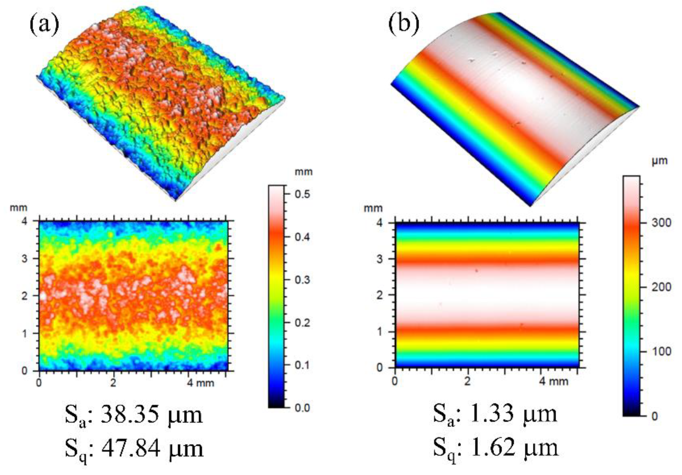
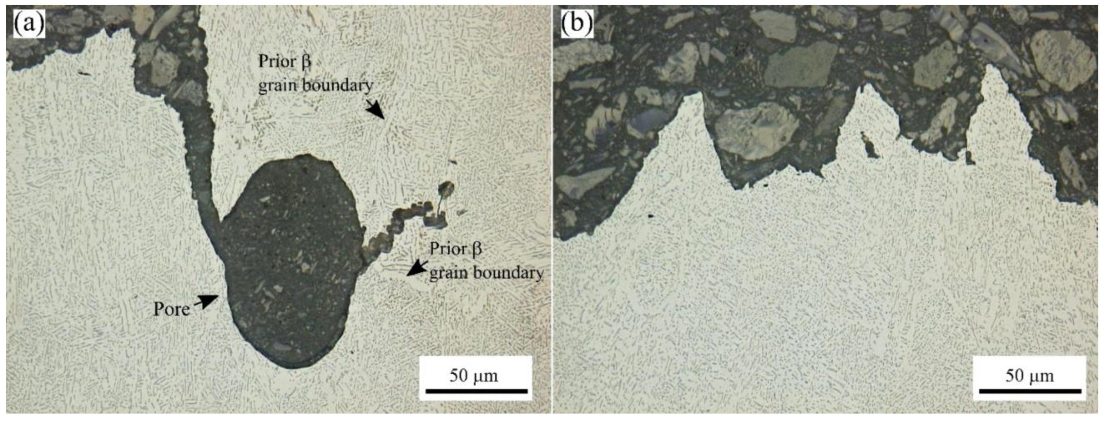
3.5. Surface Analysis

To evaluate the effect of the surface condition on the mechanical properties, select TD and FD coupons were machined. For the as-built and machined surfaces, the measured surface topography characteristics are shown in Figure 9, which depict an area of 4 mm × 5 mm on the diameter of a TD coupon. These findings are shown in Figure 9, and they agree with previously reported average surface roughness values for the as-built vertical (XZ or YZ) Ti-6Al-4V surfaces [49]. After machining, the average roughness (Sa) and root mean square roughness (Sq) were more than an order of magnitude lower than the as-built condition.

3.6. Tensile Testing

Table 4 summarizes the average static tensile properties of the OS and IS specimens in the as-built and machined surface conditions. The results for YS, UTS, and EL are the average values from five repeated uniaxial tensile tests.
Regardless of the surface finish (as-built versus machined), the average YS and UTS values for both the OS and IS coupons were higher than the minimum requirements of ASTM F2924 [22] for PBF, ASTM F1108 [50] for cast and ASTM B348 [51]/B265 [52] for wrought Ti-6Al-4V. However, both the surface finish and oxygen content significantly impacted the ductility of the OS specimens. Overall, the strength improved after machining for both the OS and IS material types, while a ductility gain was observed for the OS coupons only. In the as-built OS condition, the low ductility can be attributed to the part’s surface morphology. The surface morphology—consisting largely of sharp notch-like features—can cause local stress concentrations and act as stress raisers that foster initiation of cracks [53]. Similar drop in ductility was observed by both Persenot et al. [53] and De Formanoir et al. [32], whose work correlated the reduction in ductility with the presence of surface defects on meso-scale parts (>1 mm diameter/thickness). Accordingly, machining of the as-built surface to remove these surface defects led to increases in the strain to failure for the machined tensile specimens.
Another outcome of the mechanical assessment is the significant difference in the observed elongation between the OS and IS specimens for a similar surface roughness. The lower ductility of the OS compared to the IS coupons can be explained by considering the influence of oxygen on the dislocation and slip behaviour during plastic deformation. Ti alloys are highly reactive, with a high affinity for interstitial elements, such as oxygen, nitrogen, and hydrogen, and must be processed under protective atmospheres at temperatures above 427 °C [54]. Considering the oxygen pickup during printing, the composition of the IS specimens (0.19 wt.%) still conformed to the specifications in ASTM F2924 [22], while the excessive oxygen content, accumulated in the OS sample (0.29 wt.%), significantly deteriorated the ductility. These dissolved oxygen atoms in α-β titanium alloys occupy the octahedral interstices along the C-axis in the hcp structure of the α phase and result in lattice strains that hinder dislocation mobility. Considering the few active slip (prismatic and basal) planes of the α phase available for dislocation motion, the oxygen atoms and, in turn, the lattice strains, lock/pin the screw dislocations that glide primarily on the prismatic slip planes [55], thereby producing a hardening effect and reducing the ductility of Ti-6Al-4V.
In the as-built condition, the present study validates that the ductility is compromised at oxygen levels above 0.2 wt.% in Ti-6Al-4V produced by EBM when producing parts with a high level of nesting in the Arcam Q20+ machine. Even after machining, the ductility of the OS Ti-6Al-4V processed by EBM (with nesting) remained lower than the EL specification of 10% in ASTM F2924 [22]. This was, in fact, expected, considering the alloy (powder feedstock) did not meet grade 5 requirements. By contrast, the IS Ti-6Al-4V material—that had a powder composition of 0.18% oxygen, in accordance with the maximum allowable value of 0.2 wt.% in ASTM F2924 [22]—had relatively good ductility that surpassed the minimum specification of 10% for the EL for both the as-built and machined surface conditions.
The tensile properties of the IS Ti-6Al-4V produced in the present work (with nesting) are compared to previously reported EBM work on grade 5 Ti-6Al-4V (without nesting) in Table 5. Overall, the tensile properties of the IS Ti-6Al-4V corroborate especially well with the work of Al-Bermani et al. [30,56,57] and suggests a strong influence of the bed preheat temperature. Hence, in the present work, controlling the bed preheat temperature in the Q20+ nested build to relatively low values (326–556 °C) were effective in limiting the microstructural coarsening during the long build time and enabled adequate/balanced performance vis à vis the tensile strength and ductility. Additionally, the findings of Rafi et al. [56,57] on the influence of the surface finish on the tensile properties corroborated well with the observed improvements in the strength of the IS Ti-6Al-4V material having a machined finish relative to the as-built surface.

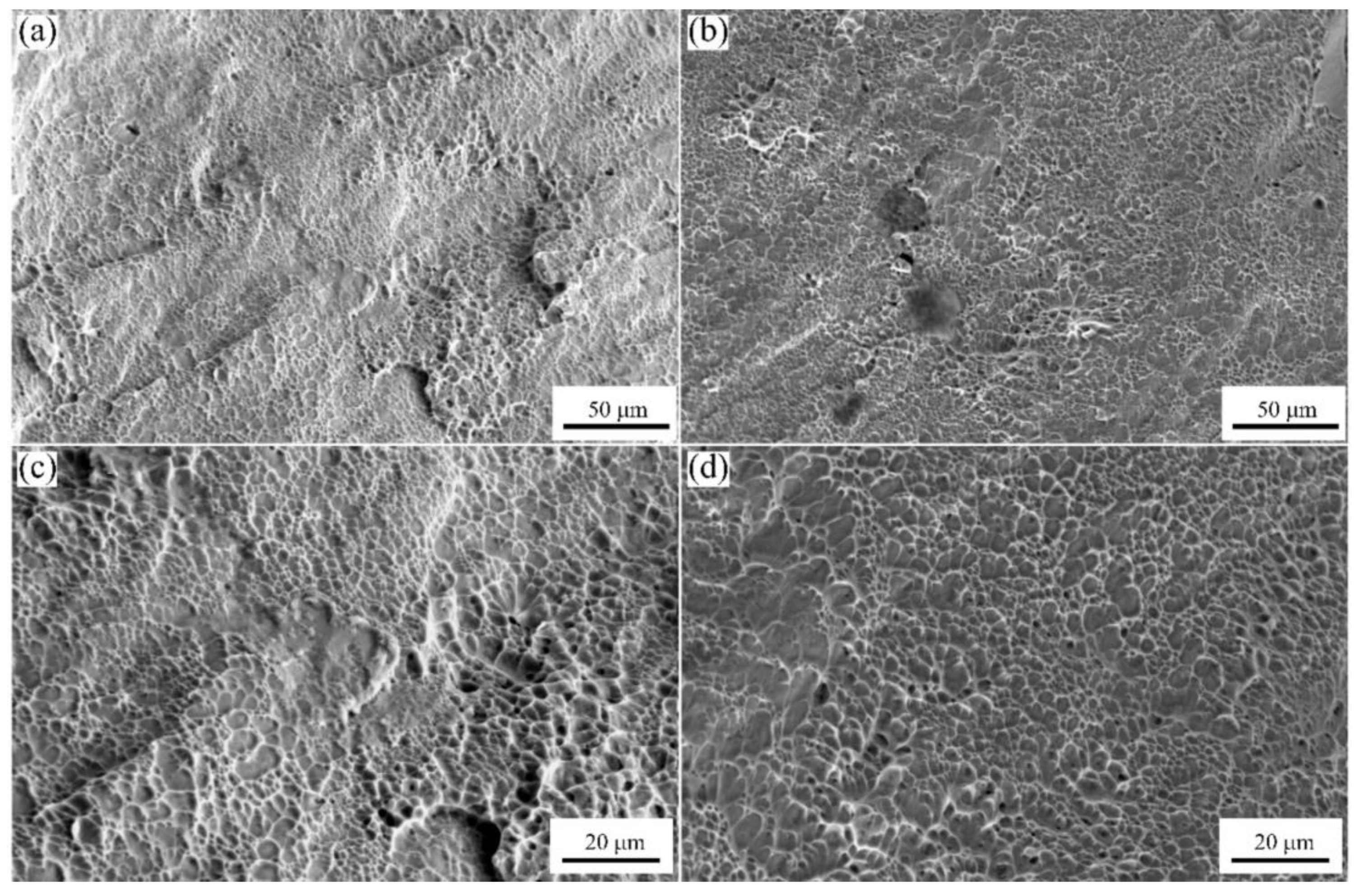
3.7. Fractography of the Tensile Test Specimens

After tensile testing, the fracture surface of the as-built and machined IS and OS TD coupons were examined using a SEM and representative micrographs are shown in Figure 10 and Figure 11, respectively. At low magnifications, a dispersion of dimples and microscopic tear ridges is apparent on the tensile fracture surface. This supports failure occurring by transgranular ductile dimple tearing, characterized by microvoid formation, growth, and coalescence of voids. From a microscale perspective, although it is difficult to directly relate the dimple size with ductility, it is known that the density, size, shape, and depth of dimples on a fracture surface are indicative of the extent of plastic deformation occurring before failure of the material. In this respect, the fracture surfaces of the OS coupons consisted of a larger number of finer and shallower dimples (Figure 11) that contrast with the fibrous surface appearance and deep conically shaped dimples (Figure 10) observed on the fractured IS coupons. These observations suggest that the amount of plastic deformation required for the process of material separation/fracture is comparatively less for the OS material and is consistent with the higher microstructural integrity, plastic deformation and elongation observed for the IS material.
To better understand the crack path, the tensile fracture surface tips of the selected TD coupons were metallographically prepared for microscopic analysis. The crack path during tensile loading was seen to propagate through the α colony structure and through pores (when present), as shown in Figure 12. In general, as α colonies are constituted by similarly aligned fine lamellae/platelets, a significant misorientation between the colonies is present. Thus, intersections of α-colonies are preferred initiation sites stemming from their short distance for crack propagation. The resulting crack path through the colony structure was observed to be tortuous with deflecting trajectories. Additionally, cracks leading to decohesion at prior-β boundaries were not observed for the EBM Ti-6Al-4V, which may explain the higher performance of the additively processed material relative to the cast alloy [65].

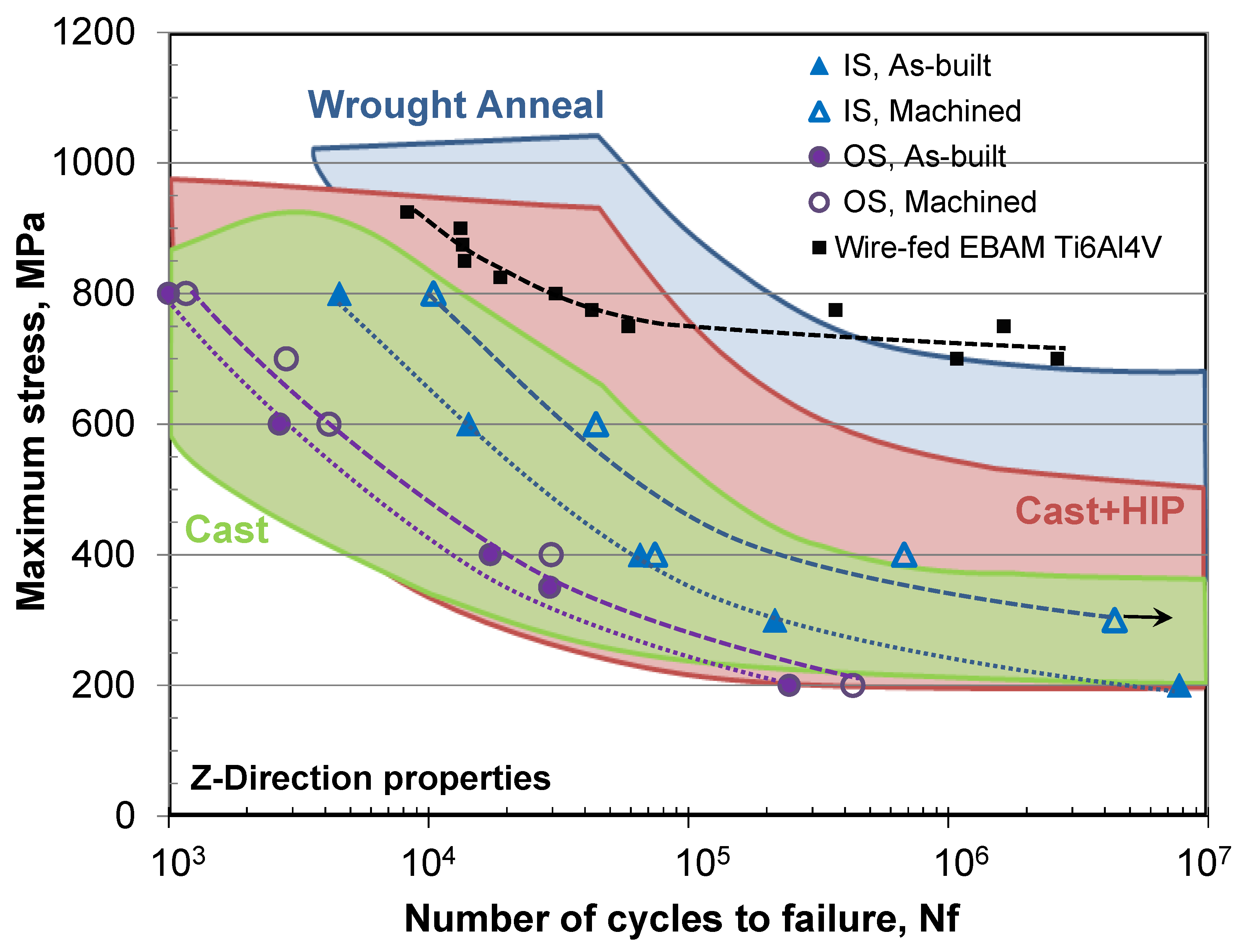
3.8. Fatigue Testing

To evaluate the design allowable thresholds for low cycle fatigue (LCF) and high cycle fatigue (HCF) of parts produced under industrially relevant conditions (nesting/stacking, as-built and machined surfaces, and OS and IS materials), cyclic loading at different stress amplitudes was undertaken at room temperature using a frequency of 6 Hz. Figure 13 presents typical fatigue life curves (also referred to as Wöhler or S-N curves) that were plotted from experimentally obtained values for the number of cycles to failure as a function of the applied (maximum) stress for both OS and IS Ti-6Al-4V materials in the as-built and machined surface conditions.
In Figure 13, the results from the present study are compared with the reported scatter bands for cast, cast plus hot isostatically pressed (HIP), and wrought/annealed processed Ti-6Al-4V [66]. Overall, the fatigue data obtained in this work is in the range of Ti-6Al-4V produced by casting and corroborates reasonably well with the properties reported in the open literature [15,57,59,67,68,69], especially considering the broad scatter of the fatigue life data [70]. The current data also indicate a strong influence on fatigue life from both the surface finish and oxygen content, as evident by the IS Ti-6Al-4V material exhibiting the highest fatigue performance, with results that were in the range of parts that had been cast plus HIP. Relative to the reported properties of Ti-6Al-4V produced by wire-fed electron beam additive manufacturing (EBAM) [14], the properties produced in the present study are considerably lower and point to the critical role that metallurgical defects (gas porosity and lack of fusion) play on the fatigue performance.
Analysis of the fatigue fracture surface was undertaken for the OS and IS FD coupons with as-built and machined surface states, and for the different combinations of LCF and HCF conditions. The failure usually occurred by surface initiation, as illustrated by the representative micrographs given in Figure 14. The damage initiation, as demarcated with arrows in Figure 14a,b, occurred typically at the notches on the rough as-built surface or near-surface asperities, pores or facets on the machined surface that were key sites for microscopic crack initiation. After initiation, the continued cyclic deformation of OS and IS materials resulted in microplastic strain (damage) accumulation, and the early crack growth region consisted of a flat and nearly featureless transgranular surface, in which quasi-cleavage facets were visible at high magnifications, as revealed in Figure 14c,d. The OS Ti-6Al-4V also exhibited porosity and lack of fusion defects in the early crack growth region, as seen in Figure 14b,d. In the final stages of stable crack growth, the onset of fatigue overloading led to fast fracture. The final failure region consisted of fine microscopic voids, as revealed in Figure 14e,f. In the case of the OS Ti-6Al4V, gas pores and lack of fusion defects were also more frequent in this tensile overload region. High-resolution imaging of the transgranular surface within the stable crack growth area revealed the presence of serial and very fine plastic fatigue striations on the surface of the cleavage facets, as illustrated in Figure 15. It is worth mentioning that at low stress amplitudes (HCF), the striations observed were finer with a narrower spacing (Figure 15b) and the microcracks appeared less prominent relative to these respective features on the LCF fracture surface (Figure 15a). Previously, Rafi et al. [56,57] also reported crack initiation on the surface of machined Ti-6Al-4V built horizontally and vertically using the EBM process (Arcam S400). Tammas-Williams et al. [71] examined the fracture surface of machined EBM Ti-6Al-4V specimens (built using an Arcam S12 system) and reported similar features to the IS material in the present study in the different regimes (initiation, early crack growth, and tensile overload).

4. Conclusions

This study provides a comprehensive framework for PBF AM of Ti-6Al-4V using the EBM process on an Arcam Q20+ industrial 3D printer. Horizontal and vertical nesting/stacking of multiple Ti-6Al-4V coupons completely filled the build chamber, to maximize the machine usage and build output. Additionally, out-of-specification (OS) and in-specification (IS) powder chemistries were evaluated to understand the impact on build integrity and static/fatigue performance. Using standard Arcam build themes for Ti-6Al-4V, comprehensive benchmarking of the coupons was undertaken to critically assess the product quality and performance, both in the as-built state and after surface machining. The main conclusions that can be reached from this research study are as follows:
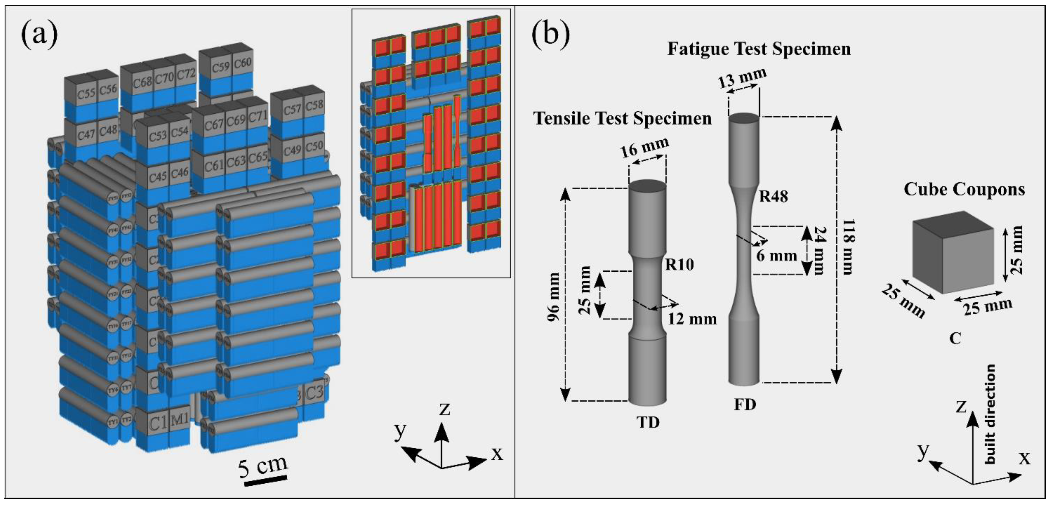
  • A build layout design that incorporated nesting/stacking of different coupon types with low density block-design supports was deliberated for the entire build volume of an Arcam Q20+ system. A printing operation of 225 h and 49 min without interruptions or print failure was shown to be possible and provides evidence for the robustness and maturity of the technology.
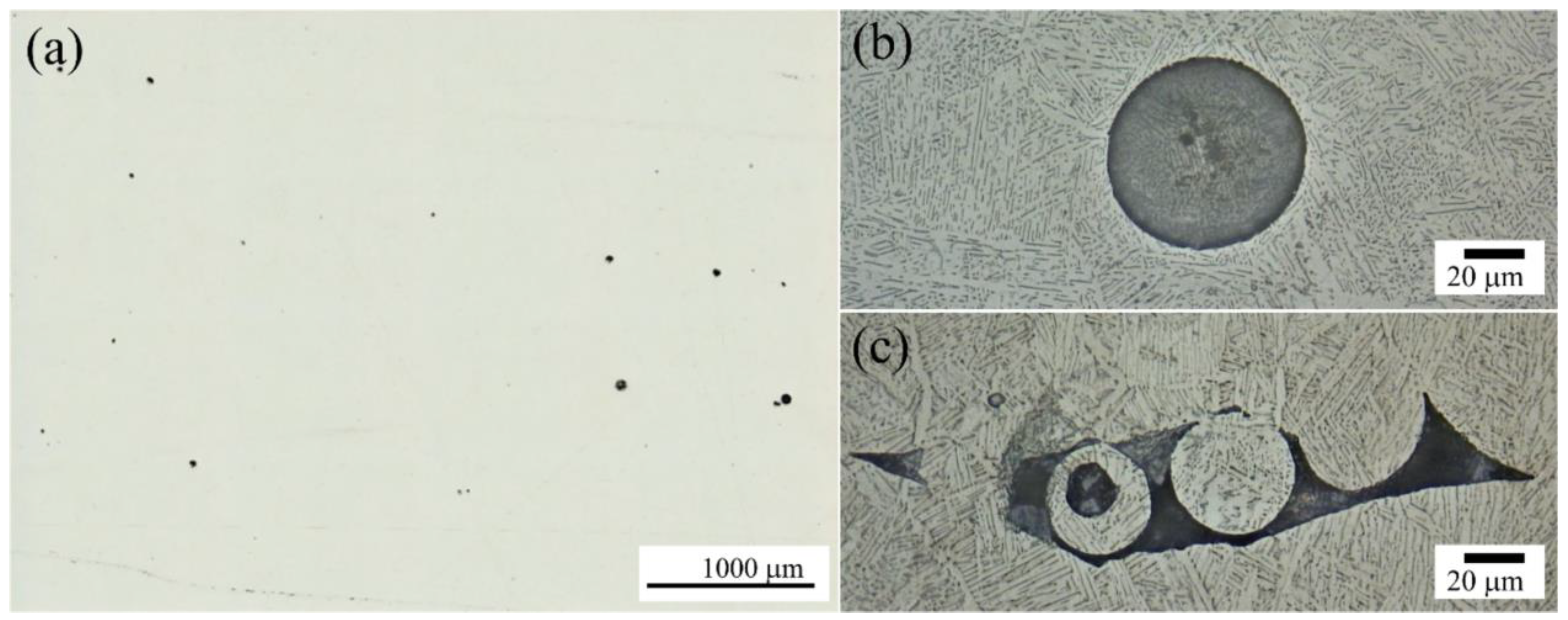
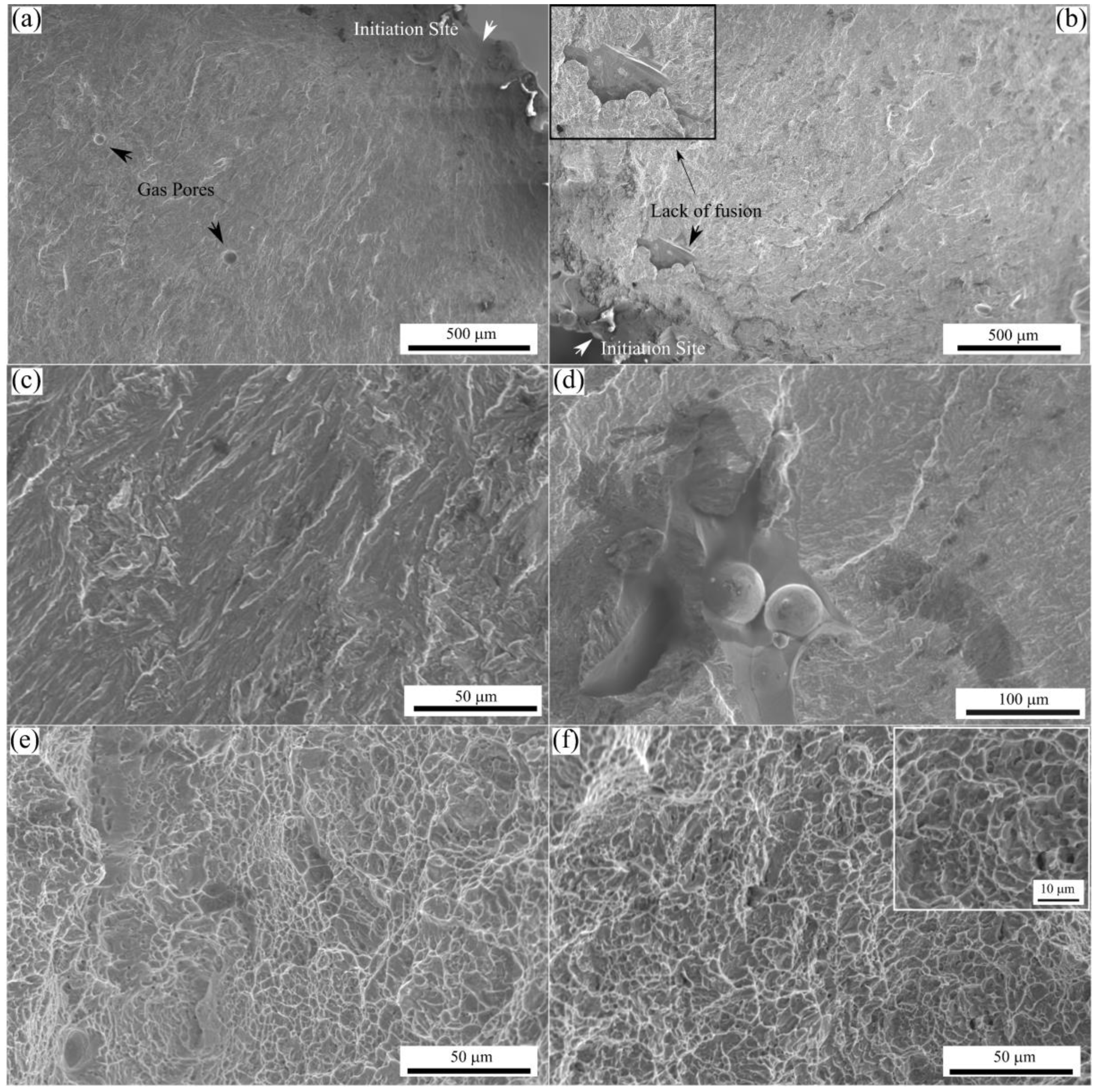
  • The Ti-6Al-4V material produced reached 99.8% of its theoretical density. Spherical gas porosity was the main defect, but irregularly shaped lack of fusion cavities was also observed, especially in the OS powder lot and in the rough surface layer (~350 μm in depth).
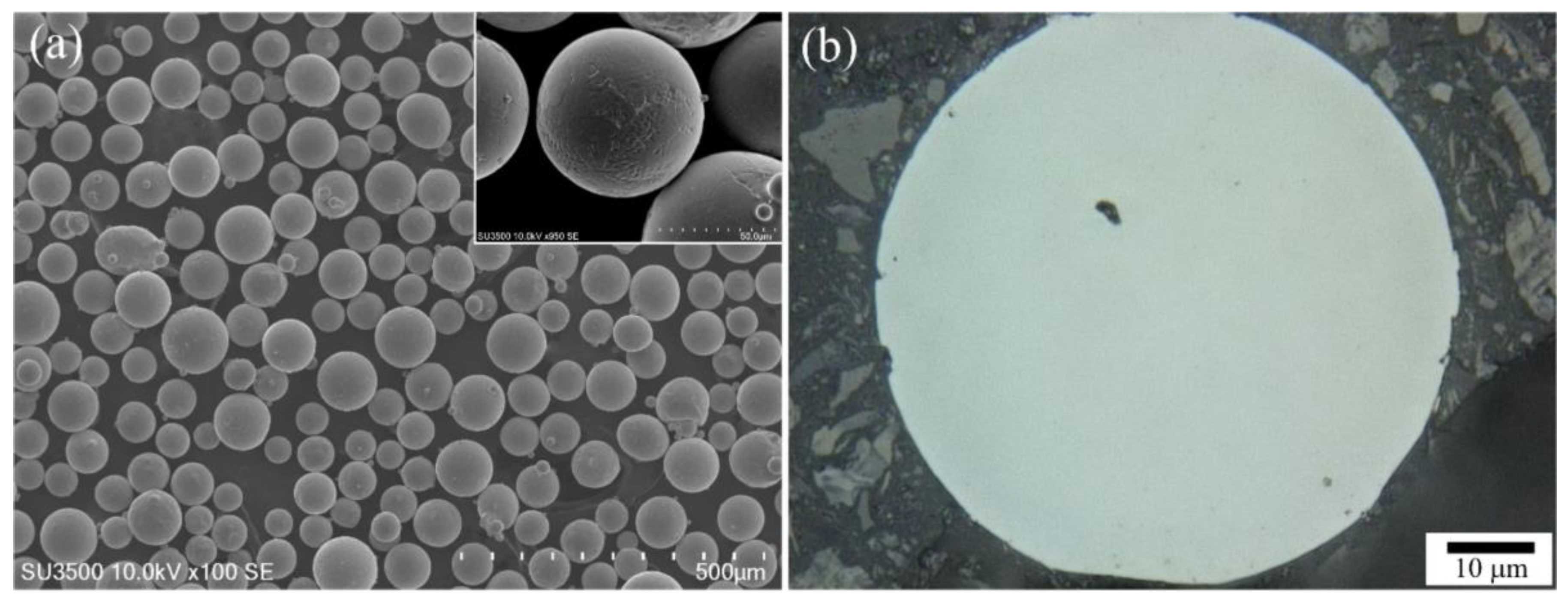
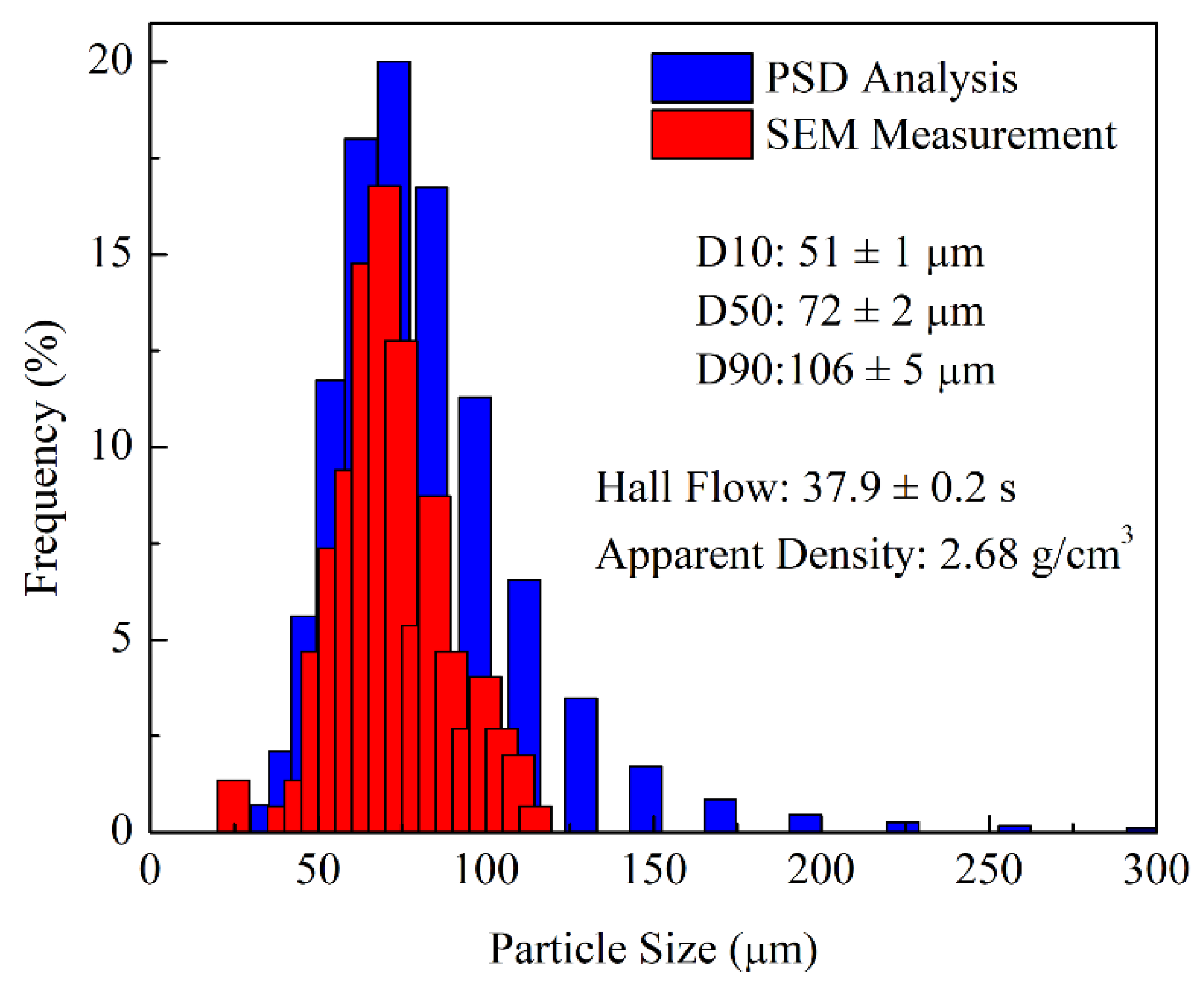
  • The coarse average powder size (71.5 μm) and high layer thickness (90 µm) generated a rough surface due to partially melted powder particles adhering to the solidified surfaces of the coupon/part. After machining, the average roughness and root mean square roughness were more than an order of magnitude lower than the as-built condition.
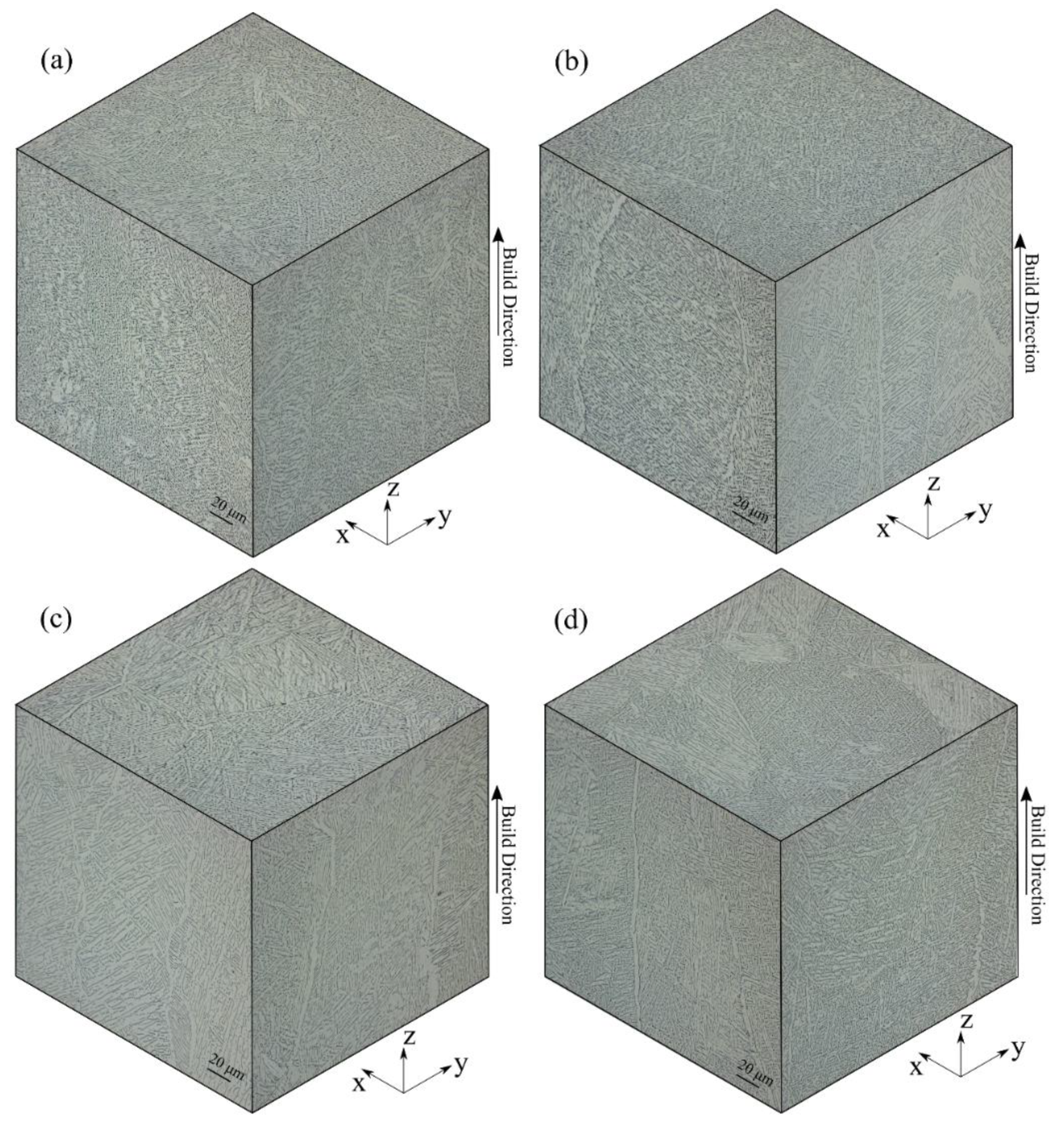
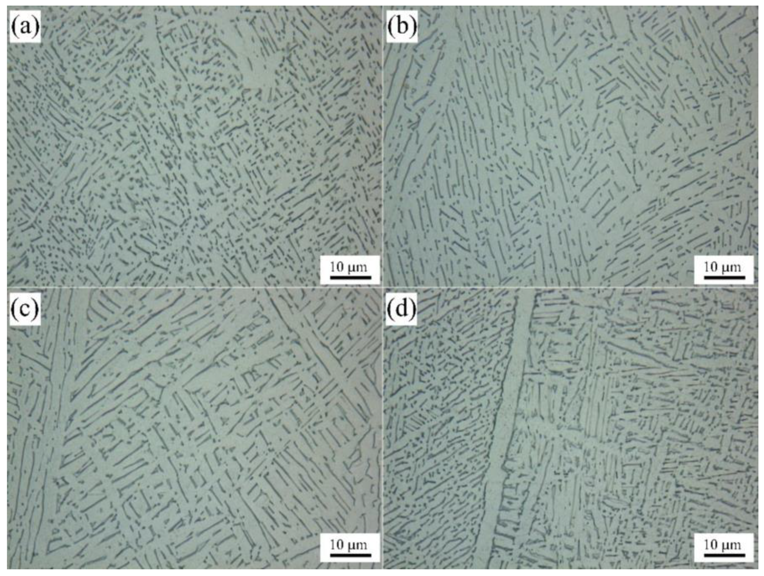
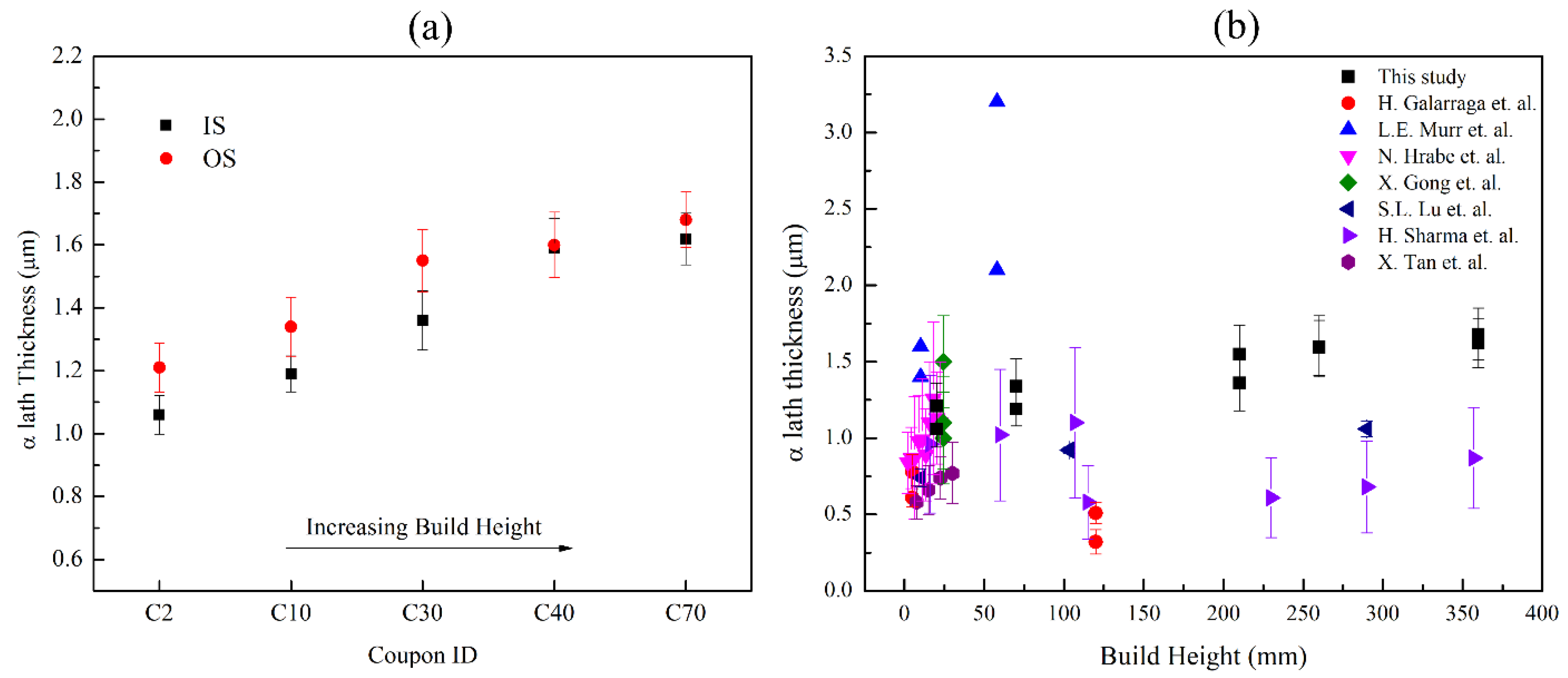
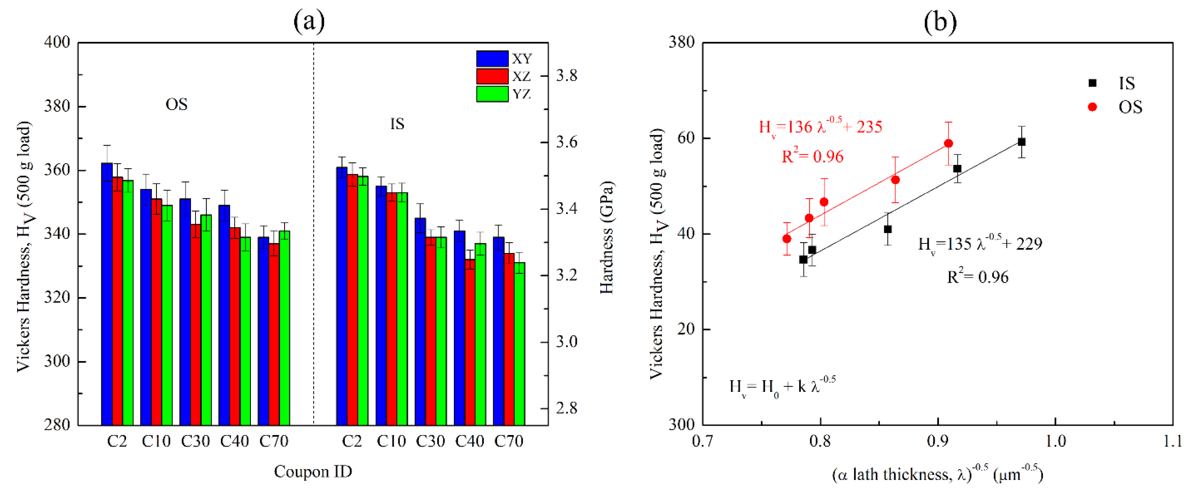
  • The as-built microstructure exhibited typical solidification features of wavy columnar prior-β grains—that were delineated by a thin grain boundary α layer—and transformed α-β laths arranged in either a colony or Widmanstätten morphology. The α lath width increased with build height by 32% and 41% for the OS and IS material, respectively, from the bottom (20 mm) to the top (360 mm) of the build.
  • This graded α-β microstructure along the build height resulted in a graded microhardness, and strong Hall-Petch correlations were established between the hardness and the average α lath width. In comparison, the influence of orientation on microhardness was relatively minor.
  • The tensile properties of the IS Ti-6Al-4V material in the as-built and machined states fully met the requirements of ASTM F2924-14 for PBF Ti-6Al-4V. By contrast, the OS Ti-6Al-4V material exhibited acceptable yield and ultimate strengths, but the ductility values were below the limit accepted by the ASTM standard. Removal of the rough surface layer by machining increased the consistency and performance of the IS and OS Ti-6Al-4V materials.
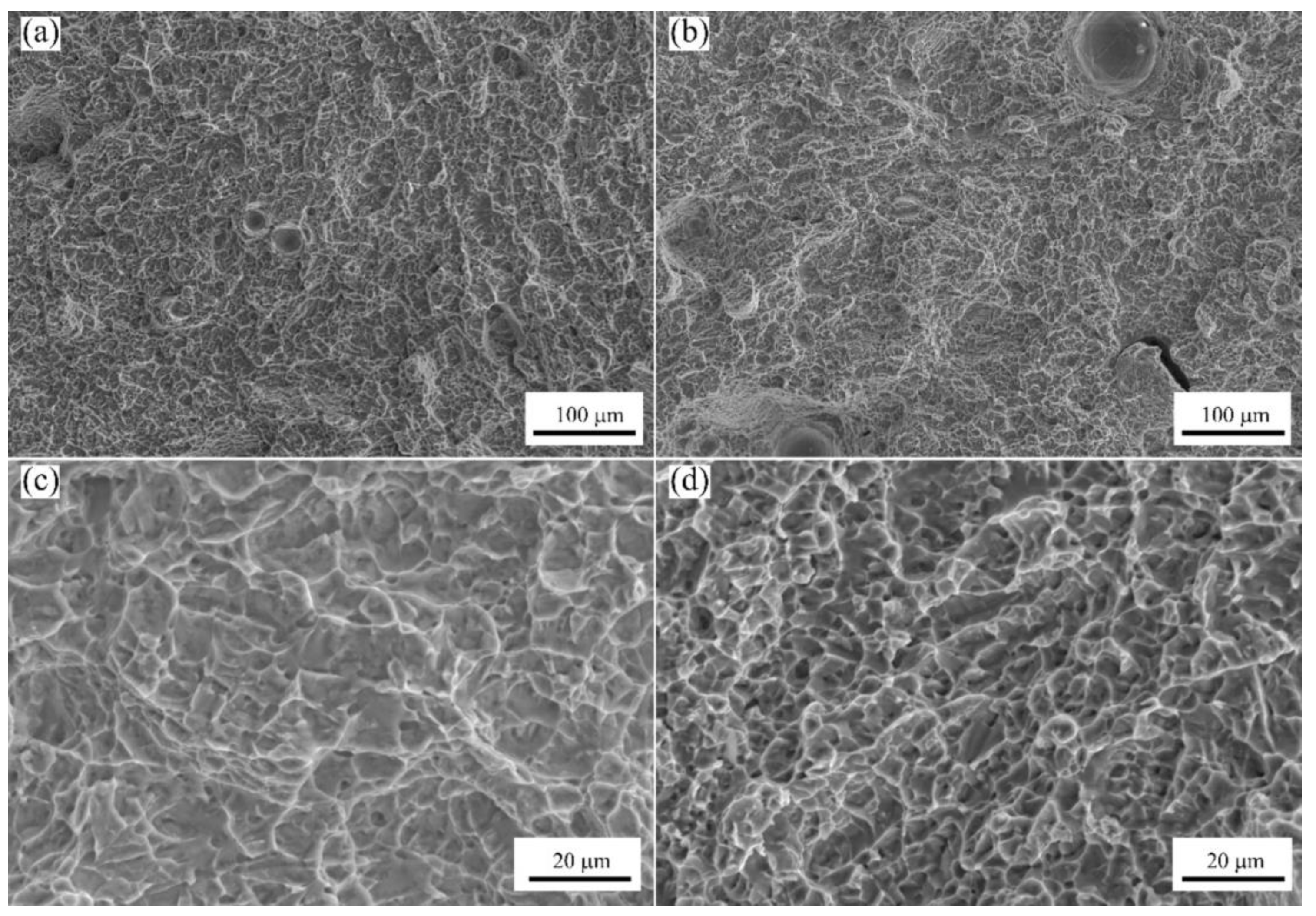
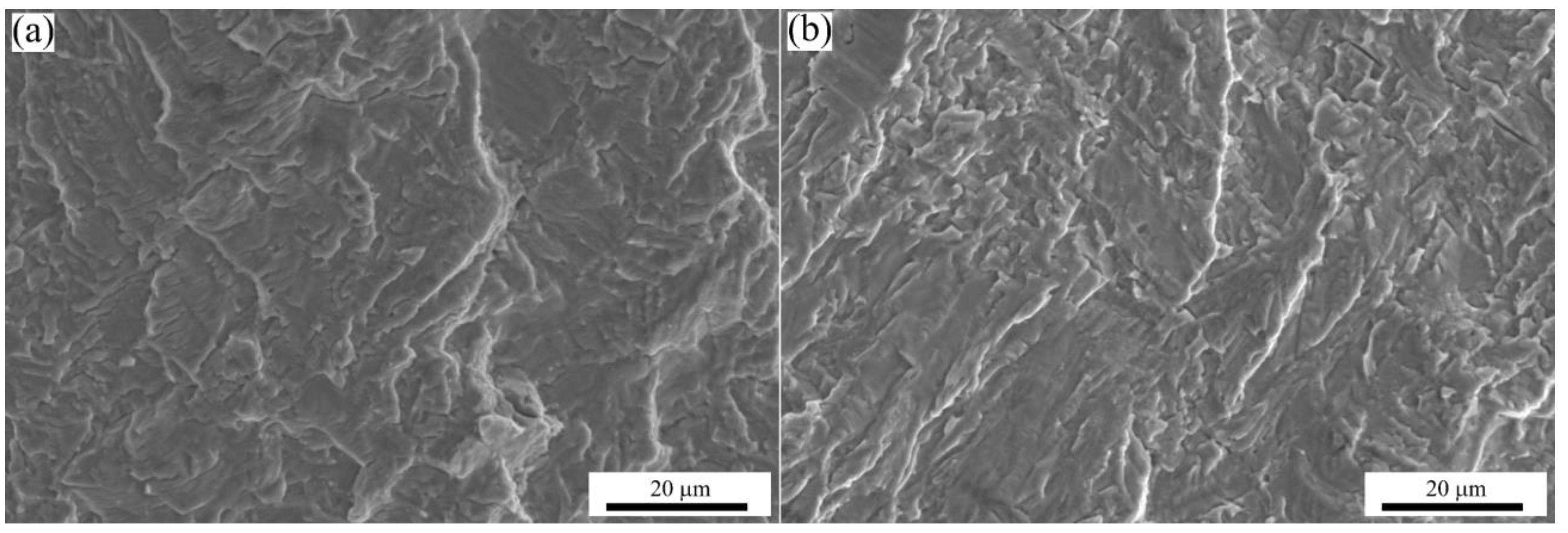
  • Tensile fracture of the OS and IS Ti-6Al-4V materials showed transgranular ductile dimple tearing, characterized by microvoid formation, growth, and coalescence of voids with a tortuous crack path propagating through the porosity in the microstructure, as well as the α colony structure.
  • The fatigue behaviour of the EBM Ti-6Al-4V material in the Z-direction was in the range of properties produced by casting. Due to the strong influence of both the surface finish and oxygen content on the fatigue strength, the IS Ti-6Al-4V material exhibited the highest performance, with results in the range of parts processed by casting plus hot isostatic pressing.

Author Contributions

Conceptualization, P.W., R.A., M.B., J.G. and P.P.; methodology, P.W., R.A., J.G. and P.P.; software, F.S.; validation, P.W., D.B., R.A. and P.P.; formal analysis, F.S., P.W., J.G. and D.B.; investigation, F.S., P.W., R.A., D.B. and J.G.; resources, P.W., M.B., R.A., P.P. and J.G.; data curation, F.S., M.B. and P.W.; writing—original draft preparation, F.S., P.W. and M.B.; writing—review and editing, J.G., R.A., P.P., D.B., P.W., M.B. and F.S.; visualization, F.S., M.B. and P.W.; supervision, M.B., P.W., D.B. and J.G.; project administration, M.B., P.W., D.B., R.A. and P.P.; funding acquisition, P.P., R.A. and J.G. All authors have read and agreed to the published version of the manuscript.

Funding

This research received financial support from the Defence Technology Sustainment (DTS) Program of the National Research Council Canada and the Department of National Defence (DND) under project A1-019998.

Data Availability Statement

The authors confirm that the data supporting the findings of this study are available within the article.

Acknowledgments

The authors are grateful to X. Pelletier (NRC) for supporting the EBM trials and metallography of the samples, P. Turnblom (NRC) for supporting surface roughness measurements, and M. Guerin (NRC) for supporting the support removal, tensile testing, and fatigue testing. The authors are also grateful to GE Additive for design and 3D printing support on the Arcam Q20+ EBM system.

Conflicts of Interest

The authors declare no conflict of interest.

References

  1. Frazier, W.E. Metal additive manufacturing: A review. J. Mater. Eng. Perform. 2014, 23, 1917–1928. [Google Scholar] [CrossRef]
  2. Sames, W.J.; List, F.A.; Pannala, S.; Dehoff, R.R.; Babu, S.S. The metallurgy and processing science of metal additive manufacturing. Int. Mater. Rev. 2016, 61, 315–360. [Google Scholar] [CrossRef]
  3. Herzog, D.; Seyda, V.; Wycisk, E.; Emmelmann, C. Additive manufacturing of metals. Acta Mater. 2016, 117, 371–392. [Google Scholar] [CrossRef]
  4. Bourell, D.L. Perspectives on Additive Manufacturing. Annu. Rev. Mater. Res. 2016, 46, 1–18. [Google Scholar] [CrossRef]
  5. Milewski, J. Additive Manufacturing of Metals; Springer: New York, NY, USA, 2017. [Google Scholar] [CrossRef]
  6. DebRoy, T.; Wei, H.L.; Zuback, J.S.; Mukherjee, T.; Elmer, J.W.; Milewski, J.O.; Beese, A.M.; Wilson-Heid, A.D.; De, A.; Zhang, W. Additive manufacturing of metallic components—Process, structure and properties. Prog. Mater. Sci. 2018, 92, 112–224. [Google Scholar] [CrossRef]
  7. Yakout, M.; Elbestawi, M. Additive Manufacturing of Composite Materials: An Overview. In Proceedings of the 6th International Conference on Virtual Machining Process Technology (VMPT), Montreal, QC, Canada, 29 May–2 June 2017. [Google Scholar]
  8. Bandyopadhyay, A.; Traxel, K.D. Invited review article: Metal-additive manufacturing—Modeling strategies for application-optimized designs. Addit. Manuf. 2018, 22, 758–774. [Google Scholar] [CrossRef]
  9. Singamneni, S.; Lv, Y.; Hewitt, A.; Chalk, R.; Thomas, W.; Jordison, D. Additive Manufacturing for the Aircraft Industry: A Review. J. Aeronaut. Aerosp. Eng. 2019, 8, 1. [Google Scholar] [CrossRef] [Green Version]
  10. Yusuf, S.M.; Cutler, S.; Gao, N. Review: The impact of metal additive manufacturing on the aerospace industry. Metals 2019, 9, 1286. [Google Scholar] [CrossRef] [Green Version]
  11. Weston, N.S.; Jackson, M. FAST-forge of titanium alloy swarf: A solid-state closed-loop recycling approach for aerospace machining waste. Metals 2020, 10, 296. [Google Scholar] [CrossRef] [Green Version]
  12. Dutta, B.; Froes, F.H. Additive manufacturing of titanium alloys. In Additive Manufacturing Handbook; CRC Press: Boca Raton, FL, USA, 2017; pp. 263–270. [Google Scholar] [CrossRef]
  13. Dutta, B.; (Sam) Froes, F.H. The Additive Manufacturing (AM) of titanium alloys. Met. Powder Rep. 2017, 72, 96–106. [Google Scholar] [CrossRef]
  14. Wanjara, P.; Watanabe, K.; De Formanoir, C.; Yang, Q.; Bescond, C.; Godet, S.; Brochu, M.; Nezaki, K.; Gholipour, J.; Patnaik, P. Titanium Alloy Repair with Wire-Feed Electron Beam Additive Manufacturing Technology. Adv. Mater. Sci. Eng. 2019, 2019, 3979471. [Google Scholar] [CrossRef] [Green Version]
  15. Lewandowski, J.J.; Seifi, M. Metal Additive Manufacturing: A Review of Mechanical Properties. Annu. Rev. Mater. Res. 2016, 46, 151–186. [Google Scholar] [CrossRef] [Green Version]
  16. Sikan, F.; Wanjara, P.; Gholipour, J.; Kumar, A.; Brochu, M. Thermo-mechanical modeling of wire-fed electron beam additive manufacturing. Materials 2021, 14, 911. [Google Scholar] [CrossRef] [PubMed]
  17. Aliprandi, P.; Giudice, F.; Guglielmino, E.; Sili, A. Tensile and creep properties improvement of Ti-6Al-4V alloy specimens produced by electron beam powder bed fusion additive manufacturing. Metals 2019, 9, 1207. [Google Scholar] [CrossRef] [Green Version]
  18. Cardon, A.; Mareau, C.; Ayed, Y.; Van Der Veen, S.; Santo, P.D. Creep behaviour of Ti-6Al-4V produced by SLM. In AIP Conference Proceedings; AIP Publishing LLC: Melville, NY, USA, 2019; Volume 2113. [Google Scholar] [CrossRef]
  19. Wanjara, P.; Gholipour, J.; Watanabe, E.; Watanabe, K.; Sugino, T.; Patnaik, P.; Sikan, F.; Brochu, M. High Frequency Vibration Fatigue Behavior of Ti6Al4V Fabricated by Wire-Fed Electron Beam Additive Manufacturing Technology. Adv. Mater. Sci. Eng. 2020, 2020, 1902567. [Google Scholar] [CrossRef]
  20. Ellyson, B.; Brochu, M.; Brochu, M. Characterization of bending vibration fatigue of SLM fabricated Ti-6Al-4V. Int. J. Fatigue 2017, 99, 25–34. [Google Scholar] [CrossRef]
  21. Jesus, J.S.; Borrego, L.P.; Ferreira, J.A.; Costa, J.D.; Capela, C. Fatigue crack growth behaviour in Ti6Al4V alloy specimens produced by selective laser melting. Int. J. Fract. 2020, 223, 123–133. [Google Scholar] [CrossRef]
  22. ASTM International. Standard Specification for Additive Manufacturing Titanium-6 Aluminum-4 Vanadium with Powder Bed Fusion (F2924); ASTM International Standards: West Conshohocken, PA, USA, 2012; pp. 1–9. [Google Scholar] [CrossRef]
  23. ASTM International. Standard Test Method for Microindentation Hardness of Materials (E384); ASTM International Standards: West Conshohocken, PA, USA, 2017. [Google Scholar]
  24. ISO. Geometrical Product Specifications (GPS)—Surface Texture: Areal (ISO 25178); ISO: Geneva, Switzerland, 2012. [Google Scholar]
  25. ASTM International. Standard Test Methods for Tension Testing of Metallic Materials (E8/E8M); ASTM International Standards: West Conshohocken, PA, USA, 2010; pp. 1–27. [Google Scholar] [CrossRef]
  26. ASTM International. Standard Practice for Conducting Force Controlled Constant Amplitude Axial Fatigue Tests of Metallic Materials (E466); ASTM International Standards: West Conshohocken, PA, USA, 2002; Volume 3, pp. 4–8. [Google Scholar] [CrossRef]
  27. Lu, S.L.; Tang, H.P.; Ning, Y.P.; Liu, N.; StJohn, D.H.; Qian, M. Microstructure and Mechanical Properties of Long Ti-6Al-4V Rods Additively Manufactured by Selective Electron Beam Melting Out of a Deep Powder Bed and the Effect of Subsequent Hot Isostatic Pressing. Metall. Mater. Trans. A Phys. Metall. Mater. Sci. 2015, 46, 3824–3834. [Google Scholar] [CrossRef]
  28. Tan, X.; Kok, Y.; Tan, Y.J.; Descoins, M.; Mangelinck, D.; Tor, S.B.; Leong, K.F.; Chua, C.K. Graded microstructure and mechanical properties of additive manufactured Ti-6Al-4V via electron beam melting. Acta Mater. 2015, 97, 1–16. [Google Scholar] [CrossRef]
  29. Antonysamy, A.A.; Meyer, J.; Prangnell, P.B. Effect of build geometry on the β-grain structure and texture in additive manufacture of Ti6Al4V by selective electron beam melting. Mater. Charact. 2013, 84, 153–168. [Google Scholar] [CrossRef]
  30. Al-Bermani, S.S.; Blackmore, M.L.; Zhang, W.; Todd, I. The origin of microstructural diversity, texture, and mechanical properties in electron beam melted Ti-6Al-4V. Metall. Mater. Trans. A Phys. Metall. Mater. Sci. 2010, 41, 3422–3434. [Google Scholar] [CrossRef]
  31. Safdar, A.; Wei, L.Y.; Snis, A.; Lai, Z. Evaluation of microstructural development in electron beam melted Ti-6Al-4V. Mater. Charact. 2012, 65, 8–15. [Google Scholar] [CrossRef]
  32. De Formanoir, C.; Michotte, S.; Rigo, O.; Germain, L.; Godet, S. Electron beam melted Ti-6Al-4V: Microstructure, texture and mechanical behavior of the as-built and heat-treated material. Mater. Sci. Eng. A 2016, 652, 105–119. [Google Scholar] [CrossRef]
  33. Sieniawski, J.; Ziaja, W.; Kubiak, K.; Motyka, M. Microstructure and Mechanical Properties of High Strength Two-Phase Titanium Alloys. In Titanium Alloys-Advances in Properties Control; IntechOpen: London, UK, 2013; pp. 1–15. [Google Scholar] [CrossRef] [Green Version]
  34. Ahmed, T.; Rack, H.J. Phase transformations during cooling in α + β titanium alloys. Mater. Sci. Eng. A 2002, 243, 206–211. [Google Scholar] [CrossRef]
  35. Welsch, G.; Boyer, R.; Collings, E.W. Materials Properties Handbook: Titanium Alloys; ASM International: Materials Park, OH, USA, 1994; pp. 483–633. [Google Scholar]
  36. Cheng, B.; Price, S.; Lydon, J.; Cooper, K.; Chou, K. On Process Temperature in Powder-Bed Electron Beam Additive Manufacturing: Model Development and Validation. J. Manuf. Sci. Eng. Trans. ASME 2014, 136, 1–12. [Google Scholar] [CrossRef]
  37. Smith, C.J.; Tammas-Williams, S.; Hernandez-Nava, E.; Todd, I. Tailoring the thermal conductivity of the powder bed in Electron Beam Melting (EBM) Additive Manufacturing. Sci. Rep. 2017, 7, 1–8. [Google Scholar] [CrossRef]
  38. Murr, L.E.; Esquivel, E.V.; Quinones, S.A.; Gaytan, S.M.; Lopez, M.I.; Martinez, E.Y.; Medina, F.; Hernandez, D.H.; Martinez, E.; Martinez, J.L.; et al. Microstructures and mechanical properties of electron beam-rapid manufactured Ti-6Al-4V biomedical prototypes compared to wrought Ti-6Al-4V. Mater. Charact. 2009, 60, 96–105. [Google Scholar] [CrossRef]
  39. Galarraga, H.; Lados, D.A.; Dehoff, R.R.; Kirka, M.M.; Nandwana, P. Effects of the microstructure and porosity on properties of Ti-6Al-4V ELI alloy fabricated by electron beam melting (EBM). Addit. Manuf. 2016, 10, 47–57. [Google Scholar] [CrossRef] [Green Version]
  40. Galarraga, H.; Warren, R.J.; Lados, D.A.; Dehoff, R.R.; Kirka, M.M.; Nandwana, P. Effects of heat treatments on microstructure and properties of Ti-6Al-4V ELI alloy fabricated by electron beam melting (EBM). Mater. Sci. Eng. A 2017, 685, 417–428. [Google Scholar] [CrossRef] [Green Version]
  41. Hrabe, N.; Quinn, T. Effects of processing on microstructure and mechanical properties of a titanium alloy (Ti-6Al-4V) fabricated using electron beam melting (EBM), Part 1: Distance from build plate and part size. Mater. Sci. Eng. A 2013, 573, 264–270. [Google Scholar] [CrossRef]
  42. Gong, X.; Lydon, J.; Cooper, K.; Chou, K. Beam speed effects on Ti-6Al-4V microstructures in electron beam additive manufacturing. J. Mater. Res. 2014, 29, 1951–1959. [Google Scholar] [CrossRef]
  43. Sharma, H.; Parfitt, D.; Syed, A.K.; Wimpenny, D.; Muzangaza, E.; Baxter, G.; Chen, B. A critical evaluation of the microstructural gradient along the build direction in electron beam melted Ti-6Al-4V alloy. Mater. Sci. Eng. A 2019, 744, 182–194. [Google Scholar] [CrossRef]
  44. Wanjara, P.; Brochu, M.; Jahazi, M. Thin Gauge Titanium Manufacturing using Multiple-Pass Electron Beam Welding. Mater. Manuf. Process. 2006, 21, 439–451. [Google Scholar] [CrossRef]
  45. Jamshidinia, M.; Atabaki, M.M.; Zahiri, M.; Kelly, S.; Sadek, A.; Kovacevic, R. Microstructural modification of Ti-6Al-4V by using an in-situ printed heat sink in Electron Beam Melting® (EBM). J. Mater. Process. Technol. 2015, 226, 264–271. [Google Scholar] [CrossRef] [Green Version]
  46. Zuback, J.S.; DebRoy, T. The hardness of additively manufactured alloys. Materials 2018, 11, 2070. [Google Scholar] [CrossRef] [PubMed] [Green Version]
  47. Yan, M.; Xu, W.; Dargusch, M.S.; Tang, H.P.; Brandt, M.; Qian, M. Review of effect of oxygen on room temperature ductility of titanium and titanium alloys. Powder Metall. 2014, 57, 251–257. [Google Scholar] [CrossRef]
  48. Tiferet, E.; Ganor, M.; Zolotaryov, D.; Garkun, A.; Hadjadj, A.; Chonin, M.; Ganor, Y.; Noiman, D.; Halevy, I.; Tevet, O.; et al. Mapping the tray of electron beam melting of Ti-6Al-4V: Properties and microstructure. Materials 2019, 12, 1470. [Google Scholar] [CrossRef] [Green Version]
  49. Sidambe, A.T. Three dimensional surface topography characterization of the electron beam melted Ti6Al4V. Met. Powder Rep. 2017, 72, 200–205. [Google Scholar] [CrossRef]
  50. ASTM International. Standard Specification for Titanium-6Aluminum-4Vanadium Alloy Castings for Surgical Implants (F1108); ASTM International Standards: West Conshohocken, PA, USA, 2010; Volume 4, pp. 1–4. [Google Scholar] [CrossRef]
  51. ASTM International. Standard Specification for Titanium and Titanium Alloy Bars and Billets (B348/B348M); ASTM International Standards: West Conshohocken, PA, USA, 2013. [Google Scholar] [CrossRef]
  52. ASTM International. Standard Specification for Titanium and Titanium Alloy Strip, Sheet, and Plate (B265); ASTM International Standards: West Conshohocken, PA, USA, 2010; Volume 3, pp. 1–9. [Google Scholar] [CrossRef]
  53. Persenot, T.; Martin, G.; Dendievel, R.; Buffiére, J.Y.; Maire, E. Enhancing the tensile properties of EBM as-built thin parts: Effect of HIP and chemical etching. Mater. Charact. 2018, 143, 82–93. [Google Scholar] [CrossRef]
  54. Donachie, M.J. Titanium: A Technical Guide, 2nd ed.; ASM International: Materials Park, OH, USA, 2000; p. 57. [Google Scholar]
  55. Polmear, I.; StJohn, D.; Nie, J.-F.; Qian, M. (Eds.) 1—The Light Metals. In Light Alloys: Metallurgy of the Light Metals; Butterworth-Heinemann: Boston, MA, USA, 2017; pp. 1–29. [Google Scholar] [CrossRef]
  56. Rafi, H.K.; Karthik, N.V.; Gong, H.; Starr, T.L.; Stucker, B.E. Microstructures and mechanical properties of Ti6Al4V parts fabricated by selective laser melting and electron beam melting. J. Mater. Eng. Perform. 2013, 22, 3872–3883. [Google Scholar] [CrossRef]
  57. Khalid Rafi, H.; Karthik, N.V.; Starr, T.L.; Stucker, B.E. Mechanical property evaluation of Ti-6Al-4V parts made using Electron Beam Melting. In Proceedings of the 23rd Annual International Solid Freeform Fabrication Symposium—An Additive Manufacturing Conference (SFF 2012), Austin, TX, USA, 6–8 August 2012; pp. 526–535. [Google Scholar]
  58. Edwards, P.; O’Conner, A.; Ramulu, M. Electron beam additive manufacturing of titanium components: Properties and performance. J. Manuf. Sci. Eng. Trans. ASME 2013, 135, 1–7. [Google Scholar] [CrossRef]
  59. Chastand, V.; Quaegebeur, P.; Maia, W.; Charkaluk, E. Comparative study of fatigue properties of Ti-6Al-4V specimens built by electron beam melting (EBM) and selective laser melting (SLM). Mater. Charact. 2018, 143, 76–81. [Google Scholar] [CrossRef]
  60. Syed, A.K.; Awd, M.; Walther, F.; Zhang, X. Microstructure and mechanical properties of as-built and heat-treated electron beam melted Ti–6Al–4V. Mater. Sci. Technol. 2019, 35, 653–660. [Google Scholar] [CrossRef]
  61. Koike, M.; Greer, P.; Owen, K.; Lilly, G.; Murr, L.E.; Gaytan, S.M.; Martinez, E.; Okabe, T. Evaluation of titanium alloys fabricated using rapid prototyping technologies-electron beam melting and laser beam melting. Materials 2011, 4, 1776–1792. [Google Scholar] [CrossRef]
  62. Zhai, Y.; Galarraga, H.; Lados, D.A. Microstructure, static properties, and fatigue crack growth mechanisms in Ti-6Al-4V fabricated by additive manufacturing: LENS and EBM. Eng. Fail. Anal. 2016, 69, 3–14. [Google Scholar] [CrossRef]
  63. Wysocki, B.; Maj, P.; Sitek, R.; Buhagiar, J.; Kurzydłowski, K.J.; Święszkowski, W. Laser and electron beam additive manufacturing methods of fabricating titanium bone implants. Appl. Sci. 2017, 7, 657. [Google Scholar] [CrossRef]
  64. Hrabe, N.; Quinn, T. Effects of processing on microstructure and mechanical properties of a titanium alloy (Ti-6Al-4V) fabricated using electron beam melting (EBM), Part 2: Energy input, orientation, and location. Mater. Sci. Eng. A 2013, 573, 271–277. [Google Scholar] [CrossRef]
  65. Feng, X.; Qiu, J.; Ma, Y.; Lei, J.; Cui, Y.; Wu, X.; Yang, R. Influence of Processing Conditions on Microstructure and Mechanical Properties of Large Thin-Wall Centrifugal Ti-6Al-4V Casting. J. Mater. Sci. Technol. 2016, 32, 362–371. [Google Scholar] [CrossRef]
  66. Eylon, D.; Newman, J.R.; Thorne, J.K. Titanium and Titanium Alloy Castings. In ASM Handbook Volume 2: Properties and Selection: Nonferrous Alloys and Special-Purpose Materials; ASM International: Materials Park, OH, USA, 1990; p. 642. [Google Scholar]
  67. Muzangaza, E. The Effects of Titanium Ti-6Al-4V Powders Manufactured Using Electron Beam Melting (EBM)—Additive Manufacturing on Metallurgical Evaluation. Ph.D. Thesis, University of Birmingham, Birmingham, UK, 2018. [Google Scholar]
  68. Gong, H.; Rafi, K.; Gu, H.; Janaki Ram, G.D.; Starr, T.; Stucker, B. Influence of defects on mechanical properties of Ti-6Al-4V components produced by selective laser melting and electron beam melting. Mater. Des. 2015, 86, 545–554. [Google Scholar] [CrossRef]
  69. Charkaluk, E.; Chastand, V. Fatigue of Additive Manufacturing Specimens: A Comparison with Casting Processes. Proceedings 2018, 2, 474. [Google Scholar] [CrossRef] [Green Version]
  70. Qian, M.; Xu, W.; Brandt, M.; Tang, H.P. Additive manufacturing and postprocessing of Ti-6Al-4V for superior mechanical properties. MRS Bull. 2016, 41, 775–783. [Google Scholar] [CrossRef] [Green Version]
  71. Tammas-Williams, S.; Withers, P.J.; Todd, I.; Prangnell, P.B. The Influence of Porosity on Fatigue Crack Initiation in Additively Manufactured Titanium Components. Sci. Rep. 2017, 7, 7308. [Google Scholar] [CrossRef] [PubMed]
Figure 1. (a) SEM micrograph showing the morphology of the powder and (b) an as-polished cross-sectional OM micrograph of a powder particle.
Jmmp 06 00021 g001
Figure 2. PSD analysis and flow characteristics of the feedstock powder.
Jmmp 06 00021 g002
Figure 3. (a) CAD layout for the manufacture of the different types of test specimens. Inset shows cross-sectional cut to reveal tensile and fatigue specimens within nesting. The support structure is highlighted in blue. (b) Geometrical details of tensile, fatigue, and cube specimens within the batch volume.
Jmmp 06 00021 g003
Figure 4. (a) Optical micrographs showing porosity overview in the as-polished condition and two types of porosity observed in the coupons: (b) spherical gas entrapment pore and (c) lack of fusion porosity with unmelted particles.
Jmmp 06 00021 g004
Figure 5. Microstructure of EBM Ti-6Al-4V in XY, XZ, and YZ planes of C coupons: (a) IS-C10, (b) OS-C10, (c) IS-C70, and (d) OS-C70.
Jmmp 06 00021 g005
Figure 6. Microstructure at higher magnification for YZ planes of C coupons: (a) IS-C10, (b) OS-C10, (c) IS-C70, and (d) OS-C70.
Jmmp 06 00021 g006
Figure 7. (a) Lath thickness of α lamellae for C2, C10, C30, C40, and C70 coupons from IS and OS material types using 90%CI statistic and (b) comparison of α lath thickness versus build height data from the present study with reported values [27,28,38,39,41,42,43].
Jmmp 06 00021 g007
Figure 8. (a) Vickers micro-hardness of coupons C2, C10, C30, C40, and C70 for both the OS and IS Ti-6Al-4V material types and (b) Vickers micro-hardness as a function of α lath width for Ti-6Al-4V fabricated by EBM using Q20+ machine.
Jmmp 06 00021 g008
Figure 9. Surface roughness profiles of tensile coupons in (a) as-built and (b) surface machined conditions.
Jmmp 06 00021 g009
Figure 10. Representative SEM fractographs of the tensile tested IS coupons in (a,c) as-built and (b,d) machined condition showing ductile fracture features (dimples and tear ridges) and some spherical gas pores remnant in the Ti-6Al-4V material produced by EBM.
Jmmp 06 00021 g010
Figure 11. Representative SEM fractographs of the tensile tested OS coupons in (a,c) as-built and (b,d) machined condition of the Ti-6Al-4V material produced by EBM.
Jmmp 06 00021 g011
Figure 12. OM micrographs of the fracture tips from TD (IS) coupons showing crack propagation dependence on (a) pores and (b) α colony microstructure in Ti-6Al-4V processed by EBM.
Jmmp 06 00021 g012
Figure 13. Room temperature experimental fatigue data for EBM Ti-6Al-4V with different surface conditions (as-built, machined) and oxygen levels (OS/IS). Data from this study are compared with wire-fed electron beam additively manufactured (EBAM) Ti-6Al-4V data from [14] and superimposed on scatter bands of cast, cast + HIP and wrought/annealed Ti-6Al-4V reproduced from [66].
Jmmp 06 00021 g013
Figure 14. Representative SEM fractography of the fatigue tested as-built FD coupons showing the crack initiation region (a,b), early crack growth region (c,d) and tensile overload region (e,f) for (a,c,e) IS and (b,d,f) OS material types. Inset in (b) shows unfused powder particles in lack of fusion defect and (f) shows dimples at higher magnification.
Jmmp 06 00021 g014
Figure 15. Representative SEM fractographs of the fatigue tested as-built FD coupons showing the stable crack growth region with fine striations in IS Ti-6Al-4V material: (a) LCF and (b) HCF.
Jmmp 06 00021 g015
Table 1. Chemical composition of the powders, in weight percentage (wt.%).
Material AlVFeCNOHTi
OS Powder6.544.020.200.0160.0160.270.0035Bal.
IS Powder6.443.970.210.0140.0180.180.0031Bal.
ASTM F2924
Min5.503.50------
Max6.754.500.300.080.050.200.015Bal.
Table 2. Chemical composition of the bulk material for the two coupon types, in weight percentage (wt.%).
MaterialAlVFeCNOHTi
OS Coupons5.664.220.190.0170.0150.290.00350Bal.
IS Coupons5.604.160.210.0140.0170.190.00312Bal.
Table 3. Optical relative density measurements for C2, C10, C30, C40 and C70 from OS and IS material types.
Material TypeOSIS
Coupon IDC2C10C30C40C70C2C10C30C40C70
Relative Density (%)99.9299.8399.8899.9399.8899.9199.8999.8799.8899.89
Standard Deviation0.040.020.020.050.030.020.010.010.020.03
Table 4. Uniaxial tensile properties of OS and IS Ti-6Al-4V in the Z-direction.
MaterialYS
(MPa)
UTS
(MPa)
EL
(%)
OS As-built913 ± 18981 ± 264.7 ± 2.0
OS Machined973 ± 201045 ± 127.8 ± 2.1
IS As-built930 ± 91015 ± 513.4 ± 1.7
IS Machined973 ± 151053 ± 313.4 ± 0.9
ASTM F2924-14 PBF Ti-6Al-4V82589510
ASTM F1108-14 Cast Ti-6Al-4V7588608
ASTM B348-19 or B265-05 grade 5 Wrought Ti-6Al-4V82889510
Table 5. Comparison of average tensile properties of Z-built Ti-6Al-4V (grade 5) produced by EBM.
ReferenceMachinePreheat (°C)SurfaceGeometry *,
Orientation
YS (MPa)UTS (MPa)EL
(%)
Present work (IS)Q20+326–556As-builtRound, V930.01015.211.9
Machined939.81058.913.4
Edwards et al. [58]A1700As-builtFlat, V8128513.6
Rafi et al. [56,57]S400700As-builtRound, V7828429.9
Machined8699289.9
Chastand et al. [59]A2680MachinedRound, V970104510.9
Syed et al. [60]A2NAMachinedFlat, H + V9059904
Koike et al. [61]A2700As-builtRound, NA7407902.2
Zhai et al. [62]A2650–750MachinedFlat and Round, V1001107311
Q101051111615
de Formanoir et al. [32]A2850As-builtFlat, V8328503.6
Polished105511004.6
Wysocki et al. [63]S12700MachinedFlat, Non-std, V84597214.2
Hrabe et al. [41,64]S12NAMachinedFlat, I, V984.11032.99.0
Flat, E, V961.01008.67.1
Bermani et al. [30]S12626MachinedRound, NA938.51029.113.2
644928.81028.913
678932.41031.911.6
700883.7993.913.6
* Geometry: Standard round/flat in ASTM E8 [25] or Non-standard (Non-std) sub-size geometry. Orientation: H = horizontal orientation (XY) and V = vertical orientation (Z). Build: I = interior and E = exterior. NA = Not available.
Publisher’s Note: MDPI stays neutral with regard to jurisdictional claims in published maps and institutional affiliations.

